

Page 1

8315 Tank Gate Interface
The 8315 scans up to 50 L&J tank gauges or
transmitters (on a single channel) via L&J
Technologies® Tankway protocol
Installation and Operations Manual
DVR Firmware Version: LJGT1_11
IOM035GVAE1313
Automation Solutions for oil & gas, defense and aviation applications
Page 2

Page 3

8315 TGI
Copyright
All rights reserved. Printed in the United States of America.
Except as permitted under the United States Copyright Act of 1976, no part of this publication
may be reproduced, stored in a retrieval system or transmitted in any form or by any means electronic, mechanical, photocopying, recording, or otherwise - without the prior written
permission of the Publisher:
Varec, Inc.
5834 Peachtree Corners East
Norcross (Atlanta), Georgia 30092
Phone: (770) 447-9202
Fax: (770) 662-8939
Trademarks Acknowledged
Varec, Inc. recognizes all other trademarks. Trademarks of other products mentioned in this
manual are held by the companies producing them.
FuelsManager® and Varec® are registered trademarks of Varec, Inc.
Acrobat Reader® is a registered trademark of Adobe Systems Incorporated.
MODBUS® is a registered trademark of Modicon, Inc.
All other product and service names mentioned are the trademarks of their respective
companies.
Disclaimer of Warranties
The contract between the Seller and the Buyer states the entire obligation of the Seller. The
contents of this instruction manual shall not become part of or modify any prior or existing
agreement, commitment, or relationship between the Seller and Buyer. There are no express or
implied warranties set out in this instruction manual. The only warranties that apply are those
in the existing contract between the Seller and Buyer.
The 8300 TGI has not been tested by Varec under all possible operational conditions, and Varec
may not have all the data relative to your application. The information in this instruction manual
is not all inclusive and does not and cannot take into account all unique situations.
Consequently, the user should review this product literature in view of his or her application. If
you have any further questions, please contact Varec for assistance.
Limitations of Seller's Liability
In the event that a court holds that this instruction manual created some new warranties, Seller's
liability shall be limited to repair or replacement under the standard warranty clause. In no case
shall the Seller's liability exceed that stated as Limitations of Remedy in the contract between
the Seller and Buyer.
Use of parts that are not manufactured or supplied by Varec voids any warranty and relieves
Varec of any obligation to service the product under warranty. Varec recommends the use of
only Varec manufactured or supplied parts to maintain or service the 8300 TGI.
Varec, Inc. i
Page 4

Tank Gate Interface
Terms of Use
The information provided in this document is provided "as is" without warranty of any kind.
Varec, Inc. disclaim all warranties, either express or implied, including the warranties of
merchantability and fitness for a particular purpose. In no event shall Varec, Inc. or its suppliers
be liable for any damages whatsoever including direct, indirect, incidental, consequential, loss
of business profits or special damages, even if Varec, Inc. or its suppliers have been advised of
the possibility of such damages.
This manual is solely intended to describe product installation and functions and should not be
used for any other purpose. It is subject to change without prior notice. This manual was
prepared with the highest degree of care. However, should you find any errors or have any
questions, contact one of our service offices or your local sales agent.
ii Installation and Operations Manual
Page 5

8315 TGI
Safety Precaution Definitions
Caution! Damage to equipment may result if this precaution is disregarded.
Warning! Direct injury to personnel or damage to equipment which can cause injury to
personnel may result if this precaution is not followed.
Safety Precautions
Read this manual carefully and make sure you understand its contents before using this product.
Follow all instructions and safety guidelines presented in this manual when using this product.
If the user does not follow these instructions properly, Varec cannot guarantee the safety of the
system.
Note Comply with all applicable regulations, codes, and standards. For safety precautions,
the user should refer to the appropriate industry or military standards.
Caution! Electrical Hazard! Read and understand static and lightning electrical protection
and grounding described in API 2003. Make certain that the installation, operation, and
maintenance conforms with the practice set forth therein.
Warning! Striking the product with a metal object could cause a spark to occur. When
removing or replacing the product in flammable or hazardous liquid storage areas, take
necessary measures to protect it from impact.
Warning! Sparks or static charge could cause fire or explosion! Mechanical connections,
worker activity and worker clothing may accumulate electrostatic charges. Care should be
used in flammable environments to avoid the hazard.
Varec, Inc. iii
Page 6

Tank Gate Interface
iv Installation and Operations Manual
Page 7

Contents
1Overview. . . . . . . . . . . . . . . . . . . . . . . . . . . . . . . . . . . . . . . . . . . . . . . . . . . . . . . . 1
1.1 Versions . . . . . . . . . . . . . . . . . . . . . . . . . . . . . . . . . . . . . . . . . . . . . . . . . . . . . . . 1
1.2 Features . . . . . . . . . . . . . . . . . . . . . . . . . . . . . . . . . . . . . . . . . . . . . . . . . . . . . . . 1
1.3 Applications. . . . . . . . . . . . . . . . . . . . . . . . . . . . . . . . . . . . . . . . . . . . . . . . . . . . . 2
1.4 Specifications . . . . . . . . . . . . . . . . . . . . . . . . . . . . . . . . . . . . . . . . . . . . . . . . . . . 2
1.4.1 System Design . . . . . . . . . . . . . . . . . . . . . . . . . . . . . . . . . . . . . . . . . . . . . 2
1.4.2 Software Functionality . . . . . . . . . . . . . . . . . . . . . . . . . . . . . . . . . . . . . . . . 2
1.4.3 Host Communication . . . . . . . . . . . . . . . . . . . . . . . . . . . . . . . . . . . . . . . . . 2
1.4.4 Modbus Functionality . . . . . . . . . . . . . . . . . . . . . . . . . . . . . . . . . . . . . . . . . 2
1.4.5 Power Supply . . . . . . . . . . . . . . . . . . . . . . . . . . . . . . . . . . . . . . . . . . . . . . 2
1.4.6 Power consumption. . . . . . . . . . . . . . . . . . . . . . . . . . . . . . . . . . . . . . . . . . 2
1.4.7 Surge protection . . . . . . . . . . . . . . . . . . . . . . . . . . . . . . . . . . . . . . . . . . . . 3
1.4.8 Operating temperature . . . . . . . . . . . . . . . . . . . . . . . . . . . . . . . . . . . . . . . . 3
1.4.9 Humidity. . . . . . . . . . . . . . . . . . . . . . . . . . . . . . . . . . . . . . . . . . . . . . . . . . 3
1.4.10 Storage temperature . . . . . . . . . . . . . . . . . . . . . . . . . . . . . . . . . . . . . . . . 3
1.4.11 Mechanical Construction. . . . . . . . . . . . . . . . . . . . . . . . . . . . . . . . . . . . . . 3
2 Hardware . . . . . . . . . . . . . . . . . . . . . . . . . . . . . . . . . . . . . . . . . . . . . . . . . . . . . . . 5
2.1 Hardware Block Diagram . . . . . . . . . . . . . . . . . . . . . . . . . . . . . . . . . . . . . . . . . . 5
2.2 Motherboard Description. . . . . . . . . . . . . . . . . . . . . . . . . . . . . . . . . . . . . . . . . . . 5
2.2.1 Power Supply . . . . . . . . . . . . . . . . . . . . . . . . . . . . . . . . . . . . . . . . . . . . . . 7
2.2.2 Switches and Indicators . . . . . . . . . . . . . . . . . . . . . . . . . . . . . . . . . . . . . . . 9
2.2.3 Communications . . . . . . . . . . . . . . . . . . . . . . . . . . . . . . . . . . . . . . . . . . . 10
3 8215 L&J Tankway Communications Interface Module . . . . . . . . . 15
3.1 Features . . . . . . . . . . . . . . . . . . . . . . . . . . . . . . . . . . . . . . . . . . . . . . . . . . . . . . 15
3.2 Description . . . . . . . . . . . . . . . . . . . . . . . . . . . . . . . . . . . . . . . . . . . . . . . . . . . . 15
3.2.1 ID DIP Switch (SW1) . . . . . . . . . . . . . . . . . . . . . . . . . . . . . . . . . . . . . . . . 16
3.2.2 LED Indicators (D1-D6) . . . . . . . . . . . . . . . . . . . . . . . . . . . . . . . . . . . . . . 17
3.2.3 External Power Connector (+48V) (J2). . . . . . . . . . . . . . . . . . . . . . . . . . . . 17
3.2.4 Surge/Shield Ground Connector (J4) . . . . . . . . . . . . . . . . . . . . . . . . . . . . . 17
3.2.5 Field Wiring terminal block (J3) . . . . . . . . . . . . . . . . . . . . . . . . . . . . . . . . . 17
4 Software Description. . . . . . . . . . . . . . . . . . . . . . . . . . . . . . . . . . . . . . . . . . . 19
4.1 Software Features. . . . . . . . . . . . . . . . . . . . . . . . . . . . . . . . . . . . . . . . . . . . . . . 19
4.1.1 Real-Time / Multitasking Executive . . . . . . . . . . . . . . . . . . . . . . . . . . . . . . 19
4.1.2 Real-Time Clock . . . . . . . . . . . . . . . . . . . . . . . . . . . . . . . . . . . . . . . . . . . 19
4.1.3 Automatic Fault Recovery. . . . . . . . . . . . . . . . . . . . . . . . . . . . . . . . . . . . . 19
4.1.4 Communications . . . . . . . . . . . . . . . . . . . . . . . . . . . . . . . . . . . . . . . . . . . 20
4.1.5 Protocols . . . . . . . . . . . . . . . . . . . . . . . . . . . . . . . . . . . . . . . . . . . . . . . . 20
Varec, Inc. v
Page 8

Contents
4.1.6 Data Scanning Task. . . . . . . . . . . . . . . . . . . . . . . . . . . . . . . . . . . . . . . . . 20
4.1.7 Database Manager . . . . . . . . . . . . . . . . . . . . . . . . . . . . . . . . . . . . . . . . . 20
4.1.8 System Tasks . . . . . . . . . . . . . . . . . . . . . . . . . . . . . . . . . . . . . . . . . . . . . 21
4.1.9 Tank Gate Interface Software Blocks. . . . . . . . . . . . . . . . . . . . . . . . . . . . . 21
4.2 Database Organization . . . . . . . . . . . . . . . . . . . . . . . . . . . . . . . . . . . . . . . . . . . 21
4.2.1 Point Format. . . . . . . . . . . . . . . . . . . . . . . . . . . . . . . . . . . . . . . . . . . . . . 21
4.2.2 Parameter Description . . . . . . . . . . . . . . . . . . . . . . . . . . . . . . . . . . . . . . . 21
4.3 Gathering Point Data . . . . . . . . . . . . . . . . . . . . . . . . . . . . . . . . . . . . . . . . . . . . 23
4.3.1 Standard Request-Response Format. . . . . . . . . . . . . . . . . . . . . . . . . . . . . 23
4.3.2 Change of State Format . . . . . . . . . . . . . . . . . . . . . . . . . . . . . . . . . . . . . . 23
4.3.3 Change of State-Related Parameters. . . . . . . . . . . . . . . . . . . . . . . . . . . . . 24
4.3.4 Modbus Communications . . . . . . . . . . . . . . . . . . . . . . . . . . . . . . . . . . . . . 24
4.3.5 Fixed Modbus Map . . . . . . . . . . . . . . . . . . . . . . . . . . . . . . . . . . . . . . . . . 26
4.3.6 GWBLK method . . . . . . . . . . . . . . . . . . . . . . . . . . . . . . . . . . . . . . . . . . . 26
4.4 Common Software Blocks. . . . . . . . . . . . . . . . . . . . . . . . . . . . . . . . . . . . . . . . . 29
4.4.1 Clock (CLK) . . . . . . . . . . . . . . . . . . . . . . . . . . . . . . . . . . . . . . . . . . . . . . 29
4.4.2 Communications (COM). . . . . . . . . . . . . . . . . . . . . . . . . . . . . . . . . . . . . . 29
4.4.3 Floating Point Register (FPREG). . . . . . . . . . . . . . . . . . . . . . . . . . . . . . . . 31
4.4.4 Emulator (EMU). . . . . . . . . . . . . . . . . . . . . . . . . . . . . . . . . . . . . . . . . . . . 31
4.4.5 EMU Gateway (EMUGW). . . . . . . . . . . . . . . . . . . . . . . . . . . . . . . . . . . . . 33
4.4.6 Gateway Block (GWBLK) . . . . . . . . . . . . . . . . . . . . . . . . . . . . . . . . . . . . . 34
4.4.7 Integer Register (IREG) . . . . . . . . . . . . . . . . . . . . . . . . . . . . . . . . . . . . . . 36
4.4.8 Modbus Gateway (MODGW) . . . . . . . . . . . . . . . . . . . . . . . . . . . . . . . . . . 36
4.4.9 Scaler Point (SCALER) . . . . . . . . . . . . . . . . . . . . . . . . . . . . . . . . . . . . . . 38
4.4.10 System Information (SYS). . . . . . . . . . . . . . . . . . . . . . . . . . . . . . . . . . . . 39
5 L&J Tankway Software Blocks . . . . . . . . . . . . . . . . . . . . . . . . . . . . . . . . . 41
5.1 L&J MCG1000 Tank Gauge (LJ1000) . . . . . . . . . . . . . . . . . . . . . . . . . . . . . . . 43
5.1.1 Parameters. . . . . . . . . . . . . . . . . . . . . . . . . . . . . . . . . . . . . . . . . . . . . . . 43
5.1.2 Application . . . . . . . . . . . . . . . . . . . . . . . . . . . . . . . . . . . . . . . . . . . . . . . 45
5.2 L&J MCG1200 Tank Gauge (LJ1200) . . . . . . . . . . . . . . . . . . . . . . . . . . . . . . . 47
5.2.1 Parameters. . . . . . . . . . . . . . . . . . . . . . . . . . . . . . . . . . . . . . . . . . . . . . . 47
5.2.2 Application . . . . . . . . . . . . . . . . . . . . . . . . . . . . . . . . . . . . . . . . . . . . . . . 48
5.3 L&J MCG1500 Tank Gauge (LJ1500) . . . . . . . . . . . . . . . . . . . . . . . . . . . . . . . 49
5.3.1 Parameters. . . . . . . . . . . . . . . . . . . . . . . . . . . . . . . . . . . . . . . . . . . . . . . 49
5.3.2 Application . . . . . . . . . . . . . . . . . . . . . . . . . . . . . . . . . . . . . . . . . . . . . . . 50
5.4 L&J MCG2000 Tank Gauge (LJ2000) . . . . . . . . . . . . . . . . . . . . . . . . . . . . . . . 53
5.4.1 Parameters. . . . . . . . . . . . . . . . . . . . . . . . . . . . . . . . . . . . . . . . . . . . . . . 53
5.4.2 Application . . . . . . . . . . . . . . . . . . . . . . . . . . . . . . . . . . . . . . . . . . . . . . . 54
5.5 L&J Scanner (LJSCAN) . . . . . . . . . . . . . . . . . . . . . . . . . . . . . . . . . . . . . . . . . . 57
5.5.1 Parameters. . . . . . . . . . . . . . . . . . . . . . . . . . . . . . . . . . . . . . . . . . . . . . . 57
5.5.2 Application . . . . . . . . . . . . . . . . . . . . . . . . . . . . . . . . . . . . . . . . . . . . . . . 58
vi Installation and Operations Manual
Page 9

Tank Gate Interface
6 Installation. . . . . . . . . . . . . . . . . . . . . . . . . . . . . . . . . . . . . . . . . . . . . . . . . . . . . 61
6.1 General Safety Guidelines . . . . . . . . . . . . . . . . . . . . . . . . . . . . . . . . . . . . . . . . 61
6.2 Installation Safety Guidelines . . . . . . . . . . . . . . . . . . . . . . . . . . . . . . . . . . . . . . 61
6.3 Installation. . . . . . . . . . . . . . . . . . . . . . . . . . . . . . . . . . . . . . . . . . . . . . . . . . . . . 62
6.3.1 Mounting the Tank Gate Interface . . . . . . . . . . . . . . . . . . . . . . . . . . . . . . . 62
6.3.2 Select the Unit Address . . . . . . . . . . . . . . . . . . . . . . . . . . . . . . . . . . . . . . 62
6.3.3 Wiring Up Power . . . . . . . . . . . . . . . . . . . . . . . . . . . . . . . . . . . . . . . . . . . 62
6.3.4 Grounding. . . . . . . . . . . . . . . . . . . . . . . . . . . . . . . . . . . . . . . . . . . . . . . . 64
6.3.5 Installing Communications . . . . . . . . . . . . . . . . . . . . . . . . . . . . . . . . . . . . 64
7 Using ViewRTU . . . . . . . . . . . . . . . . . . . . . . . . . . . . . . . . . . . . . . . . . . . . . . . . 65
7.1 Overview. . . . . . . . . . . . . . . . . . . . . . . . . . . . . . . . . . . . . . . . . . . . . . . . . . . . . . 65
7.2 System Requirements. . . . . . . . . . . . . . . . . . . . . . . . . . . . . . . . . . . . . . . . . . . . 65
7.3 Installing ViewRTU . . . . . . . . . . . . . . . . . . . . . . . . . . . . . . . . . . . . . . . . . . . . . . 65
7.4 Executing ViewRTU . . . . . . . . . . . . . . . . . . . . . . . . . . . . . . . . . . . . . . . . . . . . . 65
7.4.1 ViewRTU window . . . . . . . . . . . . . . . . . . . . . . . . . . . . . . . . . . . . . . . . . . 67
7.5 The ViewRTU Menu Bar. . . . . . . . . . . . . . . . . . . . . . . . . . . . . . . . . . . . . . . . . . 67
7.5.1 The File Menu. . . . . . . . . . . . . . . . . . . . . . . . . . . . . . . . . . . . . . . . . . . . . 67
7.5.2 The Point Menu. . . . . . . . . . . . . . . . . . . . . . . . . . . . . . . . . . . . . . . . . . . . 68
7.5.3 The Config Menu. . . . . . . . . . . . . . . . . . . . . . . . . . . . . . . . . . . . . . . . . . . 71
7.5.4 The Communications Menu . . . . . . . . . . . . . . . . . . . . . . . . . . . . . . . . . . . 73
7.5.5 The Options Menu . . . . . . . . . . . . . . . . . . . . . . . . . . . . . . . . . . . . . . . . . 75
7.5.6 The Help Menu . . . . . . . . . . . . . . . . . . . . . . . . . . . . . . . . . . . . . . . . . . . . 76
7.6 Using ViewRTU . . . . . . . . . . . . . . . . . . . . . . . . . . . . . . . . . . . . . . . . . . . . . . . . 77
7.6.1 Overview . . . . . . . . . . . . . . . . . . . . . . . . . . . . . . . . . . . . . . . . . . . . . . . . 77
7.6.2 Configuring Single Points . . . . . . . . . . . . . . . . . . . . . . . . . . . . . . . . . . . . . 78
7.6.3 To modify a Value . . . . . . . . . . . . . . . . . . . . . . . . . . . . . . . . . . . . . . . . . . 80
7.6.4 Configuring Multiple Points . . . . . . . . . . . . . . . . . . . . . . . . . . . . . . . . . . . . 82
7.6.5 Creating and Editing Connections . . . . . . . . . . . . . . . . . . . . . . . . . . . . . . . 88
8 Troubleshooting . . . . . . . . . . . . . . . . . . . . . . . . . . . . . . . . . . . . . . . . . . . . . . . 91
8.1 Overview. . . . . . . . . . . . . . . . . . . . . . . . . . . . . . . . . . . . . . . . . . . . . . . . . . . . . . 91
8.2 Troubleshooting the Tank Gate Interface . . . . . . . . . . . . . . . . . . . . . . . . . . . . . 91
8.2.1 LED Displays under normal conditions. . . . . . . . . . . . . . . . . . . . . . . . . . . . 91
8.2.2 LED Displays under Abnormal Conditions . . . . . . . . . . . . . . . . . . . . . . . . . 92
8.2.3 Using the Tank Gate Interface Push-buttons. . . . . . . . . . . . . . . . . . . . . . . . 92
8.2.4 Performing a Hard Reset . . . . . . . . . . . . . . . . . . . . . . . . . . . . . . . . . . . . . 93
8.3 Maintenance . . . . . . . . . . . . . . . . . . . . . . . . . . . . . . . . . . . . . . . . . . . . . . . . . . . 94
A Appendix - Order Codes . . . . . . . . . . . . . . . . . . . . . . . . . . . . . . . . . . . . . . . 97
Varec, Inc. vii
Page 10

Contents
viii Installation and Operations Manual
Page 11

8315 TGI Overview
1Overview
The 8300 series Tank Gate Interface acts as a tank gauge interface for data acquisition and host
gateway for tank farm, pipeline or refinery applications. Options are available for interfacing to
nearly any brand of tank gauge equipment or technologies, making it possible to integrate float
and tape transmitters, HTG, servo, magnetostrictive and radar gauges.
Each 8300 series Tank Gate Interface unit has a built-in motherboard and specific
communications module based on the local field protocol or tank gauging instrumentation
requirements. The motherboard contains a serial data link to enable communication to a host
PC, PLC, or DCS.
Note! Each intelligent module is identified by a 82xx designation that matches the product designation, for example, the 8303 TGI contains a 8203 communications module.
Each module contains its own processor for fast and reliable field data scanning. Compatibility
of every module also makes configuration of the internal database simple and straightforward.
1.1 Versions
The 8300 series Tank Gate Interface is available in a number of versions that can interface to a
variety of field devices and intelligent instrumentation via interface modules listed below:
1.2 Features
• 8303-2 Dual RS-485 (MODBUS) Communications Tank Gate Interface
• 8303-6 Dual RS-485 (GSI ASCII) Communications Interface Module
• 8310 Varec Mark/Space (Varec 1800, 1900, 4000) Tank Gate Interface
• 8311-1 Current Loop (Whessoe Bus) Tank Gate Interface
• 8311-2 Current Loop (GPE) Tank Gate Interface
• 8312 Saab (TRL/2) Tank Gate Interface
• 8314 Enraf (811, 802/812, 854, 873) Tank Gate Interface
• 8315 L&J Tankway (MCG 1000, MCG 1500, MCG 2000) Tank Gate Interface
• 8316 LON (Prime Measurement 3500 ATG) Tank Gate Interface
• 8317 Dual RS-232 Veeder Root (TLS 350) Tank Gate Interface
• Inputs are reported to Host Computer by Exception or Scanned Poll
• Built-in Software Function Library
• Surge Protection Conforming to ANSI/IEEE C37.90a-1974
• Host Communication via RS-232, RS-485, radio, modem or fiber optic link
• Industry Standard Protocol: Modbus
• Quick-Disconnect I/O Terminations
• Modular Construction for Optimum Expandability
• Non-Volatile Database
Varec, Inc. 1
Page 12

Overview Tank Gate Interface
1.3 Applications
The 8300 series Tank Gate Interface is ideally suited for Tank Farm, Terminal, Pipeline and
Refinery applications. It is an effective solution used in SCADA applications.
• Level, temperature, pressure, flow, local indication, and alarms
1.4 Specifications
1.4.1 System Design
• 16-bit processor with optional intelligent communication modules
• Intelligent field device communications
• 128K bytes Non-Volatile Database Memory
• Serial RS-232
• Visual indication - 4 LEDs on main board indicate power and status
1.4.2 Software Functionality
• Tank gauge scanning - Data acquisition of measured values from connected tank gauges/
transmitters
• Service & diagnostics*
• Gauge diagnostics
• Read level, temperature and status data from gauge/transmitter
1.4.3 Host Communication
• Host comm. ports - 2
• Comm. type:
• COM 0: RS-232C
• COM 1: RS-232C or RS485
• Baud Rate - selectable baud rate depending on equipment parameters
• Protocol - Modbus™ RTU protocol
• Mode - RTU mode, master and slave
• Media access - Master/Slave
1.4.4 Modbus Functionality
• Modbus™ commands - 3, 4, 5, 6, 15, 16
• Modbus™ mapping - Configurable
1.4.5 Power Supply
• Supply 100...240 Vac, 50/60 Hz
1.4.6 Power consumption
• 50 VA max (500 mA)
2 Installation and Operations Manual
Page 13

8315 TGI Overview
1.4.7 Surge protection
• Gas Discharge Tubes (GDTs) and clamping diodes on all field inputs, power supply inputs
and communications channels
1.4.8 Operating temperature
• -40...+185 °F (-40...+85 °C)
1.4.9 Humidity
• 5...95% (non-condensing)
1.4.10 Storage temperature
• -40...+212 °F (-40...100 °C)
1.4.11 Mechanical Construction
• Dimensions (HxDxW) - 2.5" (64 mm) x 8.6" (220 mm) x 5.2" (133 mm)
• Material - Aluminum Powder coated
*Gauge/transmitter Dependent
Varec, Inc. 3
Page 14

Overview Tank Gate Interface
4 Installation and Operations Manual
Page 15
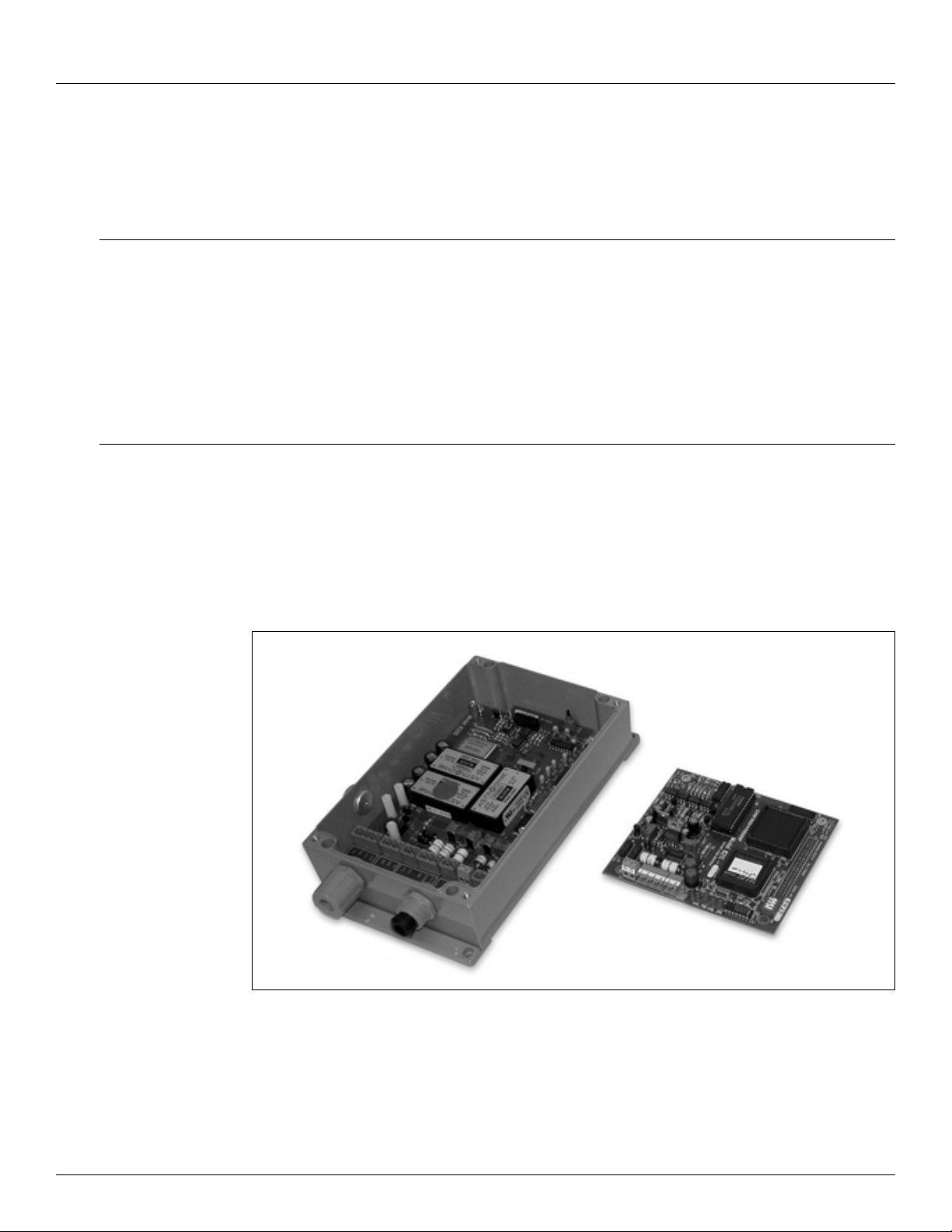
8315 TGI Hardware
2 Hardware
The Tank Gate Interface consists of an enclosure, motherboard, single tank gauge interface
module and connectors.
2.1 Hardware Block Diagram
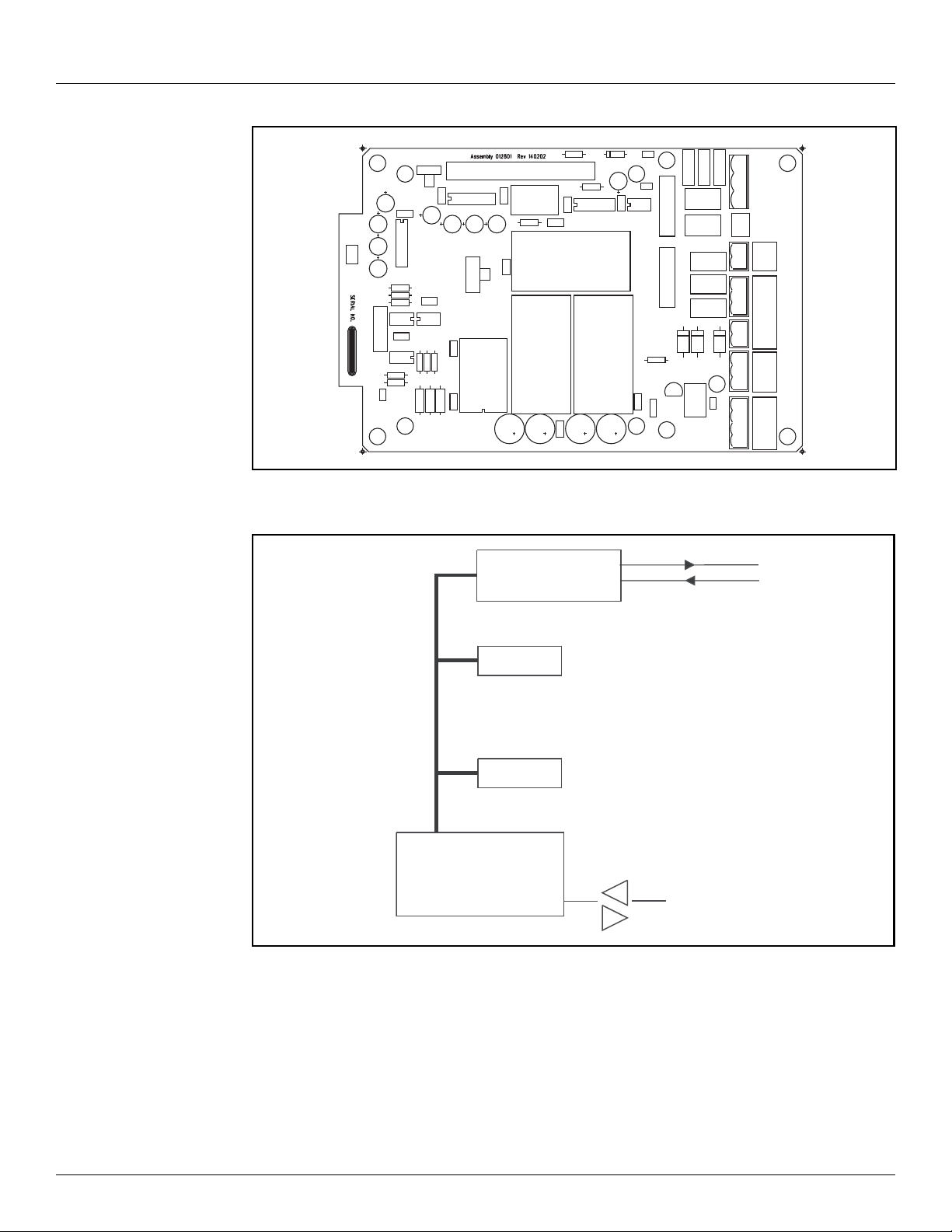
A Tank Gate Interface hardware functional block diagram is shown below. This diagram shows
the relationship between major subsystems and components in the Tank Gate Interface.
The heart of the Tank Gate Interface is an Intel 80C188EB microprocessor operating at 18.432
MHz. Designed specifically for real-time embedded applications, the µP includes timer/
counters, an interrupt controller, and chip-select circuitry. It also includes 2 serial channels that
are designated as COM0 and COM1.
2.2 Motherboard Description
The motherboard description is broken into three sections. Each section identifies the location
of the components on the motherboard. When necessary, a brief description of the component
is provided. These sections are listed below:
• Power Supply
• Switches and Indicators
• Communications
Figure 2-1: Tank Gate Interface Hardware Components
Varec, Inc. 5
Page 16
Hardware Tank Gate Interface
COM 0
RS-232
128 K
256 k
uP
Serial 0
Serial 1
PROM
Tank Gauge
Interface Circuitry
NOVRAM
HARDWARE HANDSHAKING
A
B
RESET
RS232
COM1
RS485
Figure 2-2: The Tank Gate Interface Motherboard
VFIELD=48V
VFIELD=24V
EARTH
NEUTRAL
LINE
SURGE GND
+
-
A/TXD
B/RXD
GND
RTS
CTS
TXD
RXD
GND
+15V
+5V
GND
-15V
VFIELD
COM1
COM 0 AUX POWER
Figure 2-3: Tank Gate Interface Functional Block Diagram
6 Installation and Operations Manual
Page 17
8315 TGI Hardware
EARTH
NEUTRAL
LINE
SURGE GND
+
VFIELD
EARTH
NEUTRAL
LINE
SURGE GND
A/TXD
B/RXD
GND
RTS
CTS
TXD
RXD
GND
+15V
+5V
GND
-15V
+
-
VFIELD
COM1
COM 0
AUX POWER
VFIELD=48V
VFIELD=24V
RESET
RS232
RS485
COM1
HARDWARE HANDSHAKING
A
B
2.2.1 Power Supply
• Unit AC Power terminal block (J2)
• Surge Protection terminal block (J4)
• Field Power terminal block (J3)
• Auxiliary DC Power Output terminal block (J8)
• AC Power fuses (500 mA - 250V 5x20 mm) (F1, F2)
• Field Voltage Selection Jumper (W3)
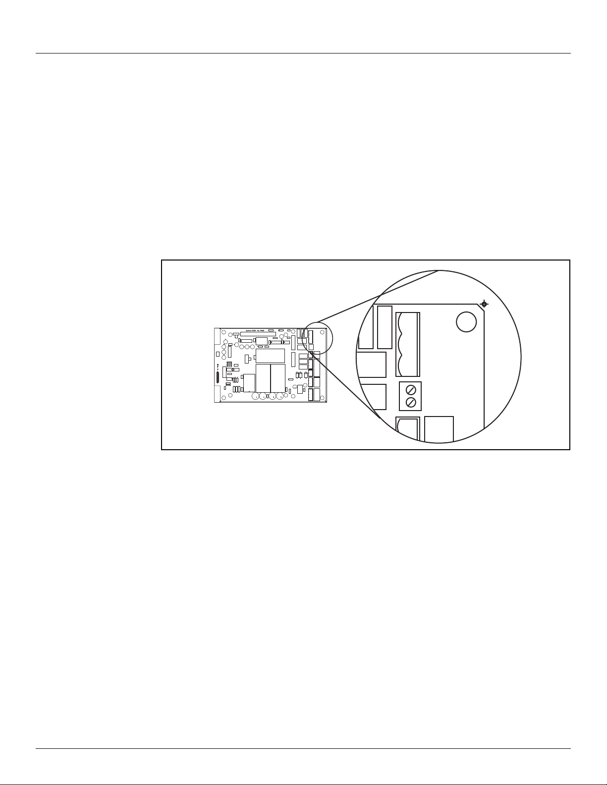
2.2.1.1 Unit AC Input Power terminal block (J2)
The Unit AC power terminal block is used to provide AC power to the Tank Gate Interface. The
power requirements for the Tank Gate Interface are 100-240 VAC, 50/60 Hz. The AC Input
Power terminal block is shown in the figure below.
J2
HARDWARE HANDSHAKING
RESET
RS232
COM1
RS485
EARTH
NEUTRAL
LINE
SURGE GND
VFIELD
A/TXD
B/RXD
COM1
GND
RTS
CTS
TXD
COM 0
RXD
GND
AUX POWER
VFIELD=48V
+15V
VFIELD=24V
+5V
GND
-15V
J4
Figure 2-4: AC Input Terminal Block
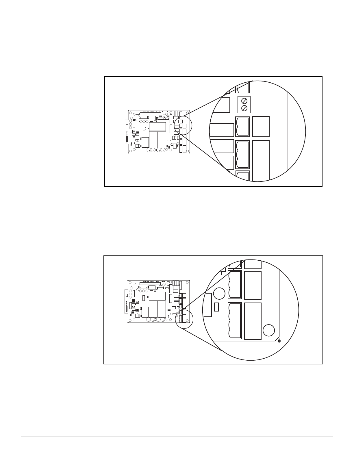
2.2.1.2 Surge Protection (Surge Gnd) terminal block (J4)
The Surge Gnd terminal block is used to connect the surge protection components (gas tubes,
MOVs) to earth ground. Ensure there is a low impedance path (< 1ohm) to earth ground (a
ground rod or grounding system).
Varec, Inc. 7
Page 18
Hardware Tank Gate Interface
LINE
SURGE GND
A/TXD
B/RXD
GND
+
-
VFIELD
COM1
J3
J4
EARTH
NEUTRAL
LINE
SURGE GND
A/TXD
B/RXD
GND
RTS
CTS
TXD
RXD
GND
+15V
+5V
GND
-15V
+
-
VFIELD
COM1
COM 0 AUX POWER
VFIELD=48V
VFIELD=24V
RESET
RS232
RS485
COM1
HARDWARE HANDSHAKING
A
B
CTS
TXD
RXD
GND
+15V
+5V
GND
-15V
COM 0 AUX POWER
J8
J7
2.2.1.3 Field Power (VFIELD) terminal block (J3)
The Field Power terminal block, referred to as VFIELD, is used to provide power for field
instruments. The output is configurable using jumpers (Jumper W3, discussed below).
Figure 2-5: Field Power Terminal Block
2.2.1.4 Auxiliary DC Output Power terminal block (J8)
The Auxiliary power terminal block is used when external equipment must be powered from the
Tank Gate Interface’s internal power supply. The triple output power supply provides +5, +15
and -15 Volts. These are rated 210 mA, 50 mA, and 5 mA, respectively. The DC Power terminal
block is shown below.
T
HARDWARE HANDSHAKING
A
B
RESET
RS232
COM1
RS485
8 Installation and Operations Manual
Figure 2-6: DC Input Voltage Terminal Block
EARTH
NEUTRAL
LINE
SURGE GND
VFIELD
+
-
A/TXD
B/RXD
COM1
GND
RTS
CTS
TXD
COM 0 AUX POWER
RXD
GND
VFIELD=48V
+15V
VFIELD=24V
+5V
GND
-15V
Page 19
8315 TGI Hardware
VFIELD=48V
VFIELD=24V
J8
J7
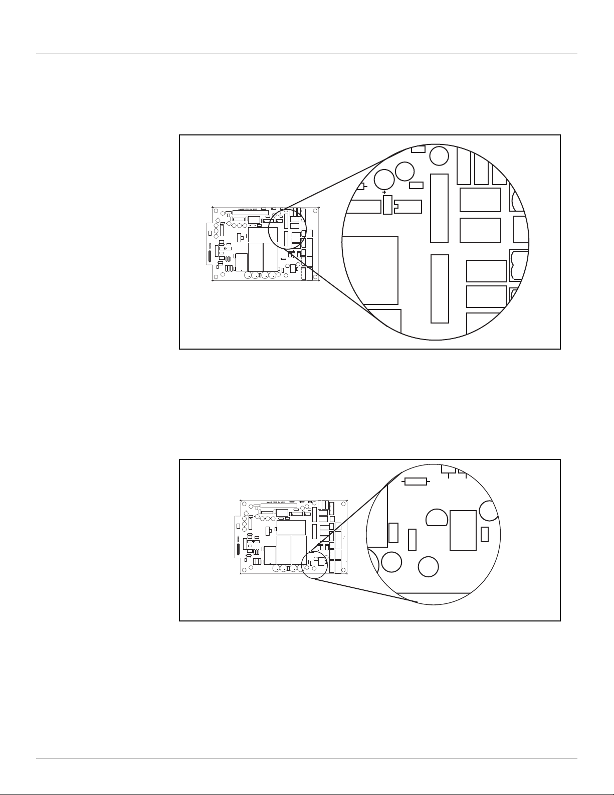
2.2.1.5 AC Power Fuses (F1,F2)
The AC Power Fuses provide protection for the AC input power. The two fuses, F1 and F2, are
rated at 500 mA, 250 V.
F1
HARDWARE HANDSHAKING
A
B
RESET
RS232
COM1
RS485
EARTH
NEUTRAL
LINE
SURGE GND
VFIELD
+
-
A/TXD
B/RXD
COM1
GND
RTS
CTS
TXD
COM 0 AUX POWER
RXD
GND
VFIELD=48V
+15V
VFIELD=24V
+5V
GND
-15V
F2
Figure 2-7: AC Power Fuse
2.2.1.6 Field Voltage Selection Jumper (W3)
The Field Voltage Selection Jumper W3 determines the voltage available at the VFIELD terminals
(J3). The Field Voltage can be configured for +24 VDC or +48VDC. At +24VDC, there is 230 mA
of field power available. At +48VDC, there is 230 mA of field power available.
HARDWARE HANDSHAKING
A
B
RESET
RS232
COM1
RS485
EARTH
NEUTRAL
LINE
SURGE GND
VFIELD
+
-
A/TXD
B/RXD
COM1
GND
RTS
CTS
TXD
COM 0 AUX POWER
RXD
GND
VFIELD=48V
+15V
VFIELD=24V
+5V
GND
-15V
W3
Figure 2-8: Selection Jumper W3
2.2.2 Switches and Indicators
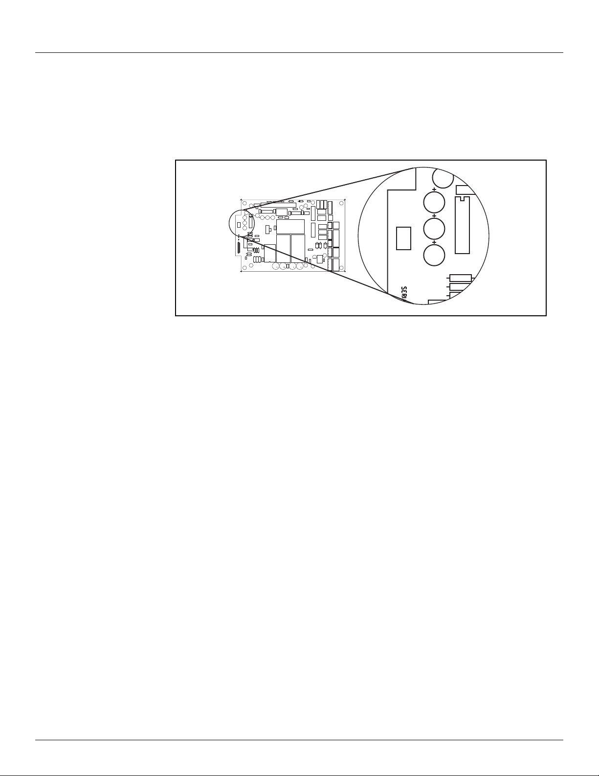
2.2.2.1 Reset push-button (SW3)
Varec, Inc. 9
The RESET Switch is used to re-initialize the system hardware by causing it to go to a known
starting state. This switch may be pressed at any time; however, it will do the following:
Page 20
Hardware Tank Gate Interface
RESET
• Re initialize System Hardware
• Clear Scratch Memory
• Verify Database and Re initialize if Invalid
• Reset All Timers
• Enable Communications
HARDWARE HANDSHAKING
A
B
RESET
RS232
COM1
RS485
EARTH
NEUTRAL
LINE
SURGE GND
VFIELD
+
-
A/TXD
B/RXD
COM1
GND
RTS
CTS
TXD
COM 0 AUX POWER
RXD
GND
VFIELD=48V
+15V
VFIELD=24V
+5V
GND
-15V
SW3
Figure 2-9: Switches SW3 on the Tank Gate Interface Motherboard
2.2.2.2 Hard Reset
A special form of Reset is available for occasions when the battery backed-up data base must
be re-initialized. This type of reset, the Hard Reset, can be performed before a database is
downloaded from a host PC.
Caution! The Hard Reset should be used as a last resort if the Tank Gate Interface is not
functioning. A Hard reset clears the installed database. For the Hard Reset procedure, refer
to the Troubleshooting and Maintenance chapter.
2.2.3 Communications
The Communications installation requires connection of the appropriate communication cable
to one of two connectors. The available options include RS-232 and RS-485 communications.
• COM0 (RS-232) (J7)
• COM1 (RS-232 or RS-485) (J5)
• COM1 Transmit Control (RS-232) (J6)
• COM1 Hardware Handshaking Switch (SW1)
• COM1 RS-232/RS-485 Selection Switch (SW2)
• COM1 RS-485 Terminating Resistor Jumper (W2)
Note COM1 is not available on the 8315 Tank Gate Interface
10 Installation and Operations Manual
Page 21
8315 TGI Hardware
A/TXD
B/RXD
GND
RTS
CTS
TXD
RXD
GND
+15V
+
-
VFIELD
COM1
COM 0 AUX POW
J7
J5
J6
EARTH
NEUTRAL
LINE
SURGE GND
A/TXD
B/RXD
GND
RTS
CTS
TXD
RXD
GND
+15V
+5V
GND
-15V
+
-
VFIELD
COM1
COM 0 AUX POWER
VFIELD=48V
VFIELD=24V
RESET
RS232
RS485
COM1
HARDWARE HANDSHAKING
A
B
EARTH
NEUTRAL
LINE
SURGE GND
A/TXD
B/RXD
GND
RTS
CTS
TXD
RXD
GND
+15V
+5V
GND
-15V
+
-
VFIELD
COM1
COM 0 AUX POWER
VFIELD=48V
VFIELD=24V
RESET
RS232
RS485
COM1
HARDWARE HANDSHAKING
A
B
CTS
TXD
RXD
GND
+15V
+5V
GND
-15V
COM 0 AUX POWER
J8
J7
Figure 2-10: COM1 J5 Terminal Block
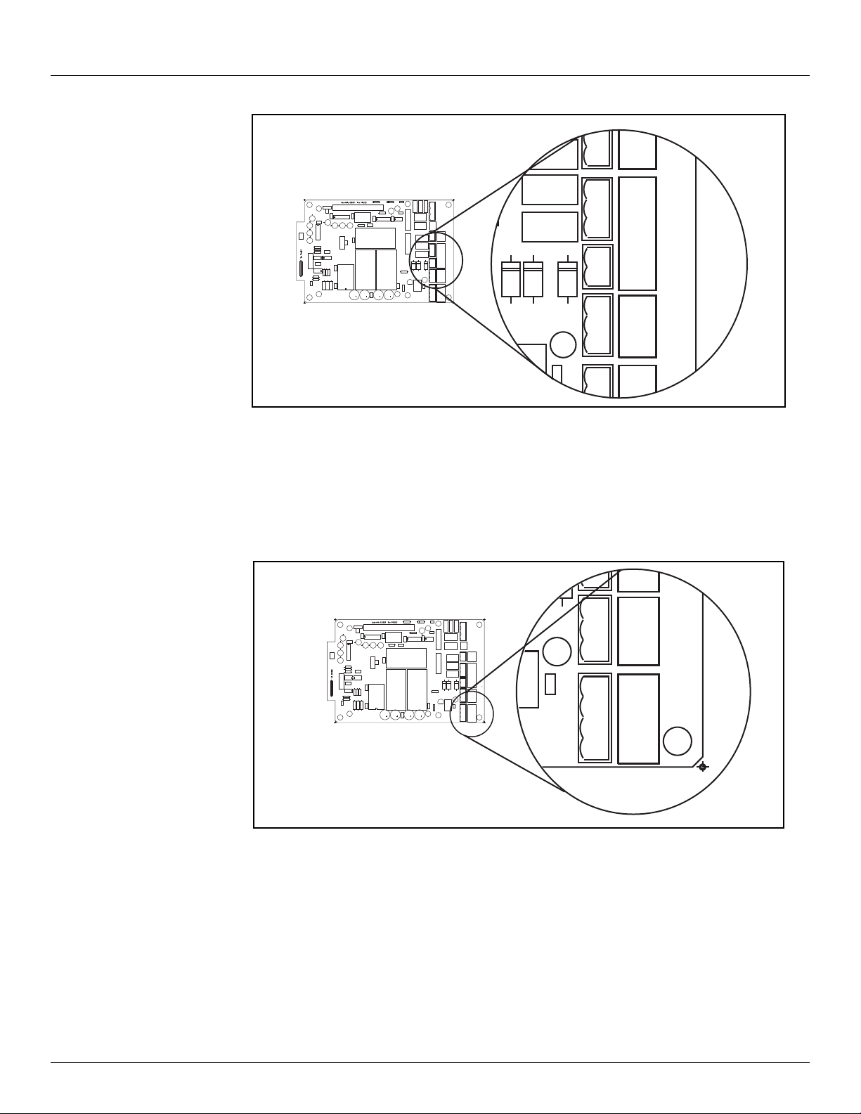
2.2.3.1 COM0 (J7)
COM0 is an RS-232 port for use in diagnostic testing/local programming or communications to
a host system. The protocol defaults to Tank Gate Interface Slave at the 9600 baud, 8 data bits,
and no parity (for use with ViewRTU or FuelsManager).
Varec, Inc. 11
Figure 2-11: COM0 J7 Terminal Block
2.2.3.2 COM1 (RS-232/RS-485) (J5)
Note COM1 is not available on the 8315 Tank Gate Interface
RS-232 is one of the two types of high-speed serial communications channels available to
interface to Host systems using several different protocols. RS-232 will operate at distances up
to 100 feet, while RS-485 allows multidrop communications at distances up to 4000 feet. RS232 can be used for flexibility in configuring other types of communications links. Other
variations of RS-232 communications interfaces include radio, modem and fiber optic
interfaces.
Page 22
Hardware Tank Gate Interface
EARTH
NEUTRAL
LINE
SURGE GND
A/TXD
B/RXD
GND
RTS
CTS
TXD
RXD
GND
+15V
+5V
GND
-15V
+
-
VFIELD
COM1
COM 0 AUX POWER
VFIELD=48V
VFIELD=24V
RESET
RS232
RS485
COM1
HARDWARE HANDSHAKING
A
B
RS232
RS485
COM1
SW2
HARDWARE HANDSHAKING
A
B
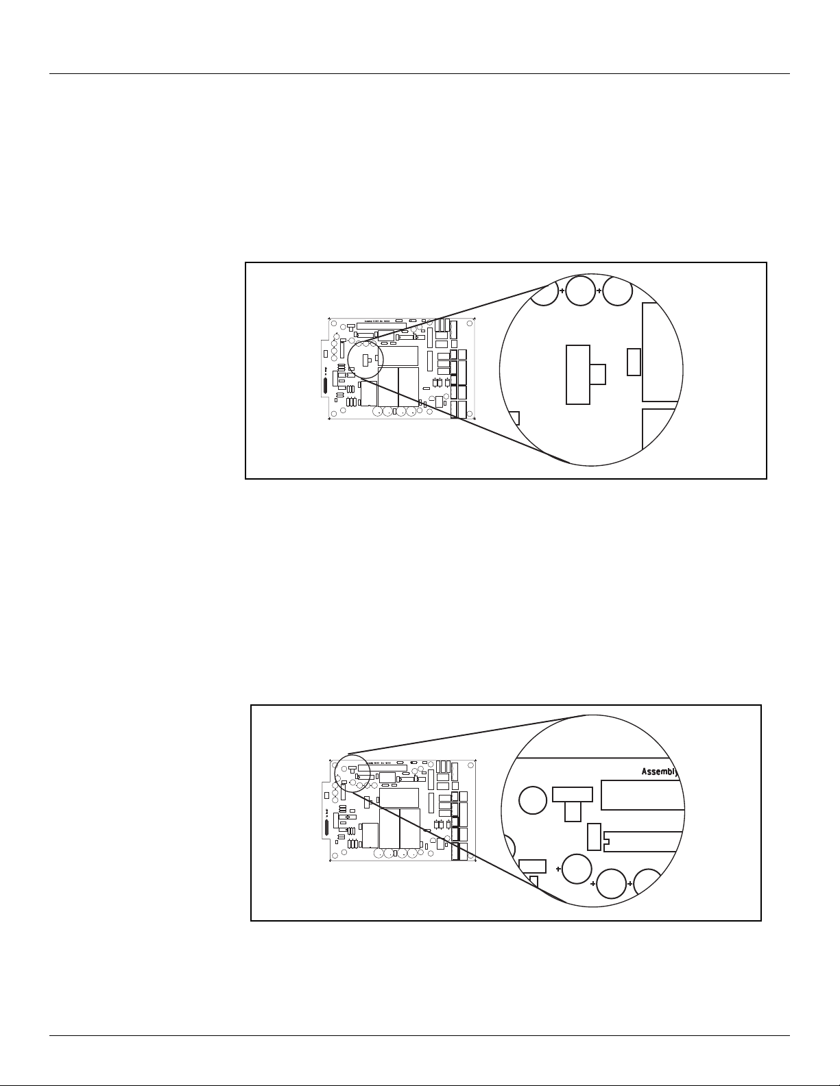
The choice of RS-232 or RS-485 is determined by the COM RS-232/RS-485 Selection Switch
SW2.
2.2.3.3 COM1 RS232/RS-485 Selection Switch (SW2)
Note COM1 is not available on the 8315 Tank Gate Interface
Switch SW2 determines whether RS-232 or RS485 is used. Note that the Hardware Handshaking
Switch SW1 affects the operation of COM1.
Figure 2-12: COM1 SW2 Switch
2.2.3.4 COM1 Hardware Handshaking Switch (SW1)
Note COM1 is not available on the 8315 Tank Gate Interface
For RS-232, there are two different settings. One setting is used if hardware handshaking (RTS/
CTS) is required. The other setting eliminates the need for hardware handshaking. Set the
Hardware Handshaking Switch to the ‘A’ position to use RTS/CTS when a modem or signal
converter is involved and requires RTS/CTS to operate. The RTS and CTS signals will be available
on terminal block J6. If the connection is direct using RS-232, jumper RTS to CTS by setting SW1
to the ‘B’ position.
HARDWARE HANDSHAKING
A
B
RESET
RS232
COM1
RS485
EARTH
NEUTRAL
LINE
SURGE GND
VFIELD
+
-
A/TXD
B/RXD
COM1
GND
RTS
CTS
TXD
COM 0 AUX POWER
RXD
GND
VFIELD=48V
+15V
VFIELD=24V
+5V
GND
-15V
SW1
12 Installation and Operations Manual
Figure 2-13: COM1 SW1 Switch
Page 23
8315 TGI Hardware
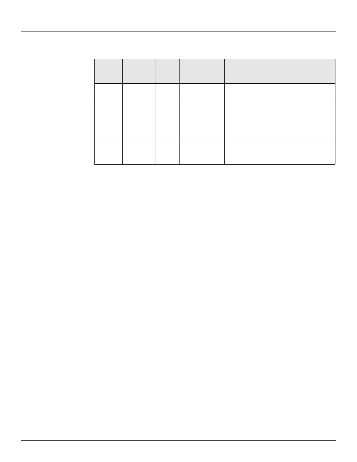
For RS-485, set the Hardware Handshaking Switch SW1 to the ‘A’ position. Refer to the following
table:.
Comm.
Physical
Layer
RS-232 No A UP (towards the
RS-232 Yes B UP (towards the
RS-485 Yes A DOWN (towards
Hardware
Handshake
SW1
Setting
SW2
Setting
RS-232 side)
RS-232 side)
the RS-485
side)
Notes
Use with a PC. Signals at terminal block J5 will
be RS-232
Use to communicate to systems that require
Request To Send (RTS) in order to transmit
(Modems, Radios, etc.)
RTS and CTS signals will be available at
terminal block J6
Always SW1 set to the A position when using
RS-485..
Table 2-1: Tank Gate Interface Communications Cable
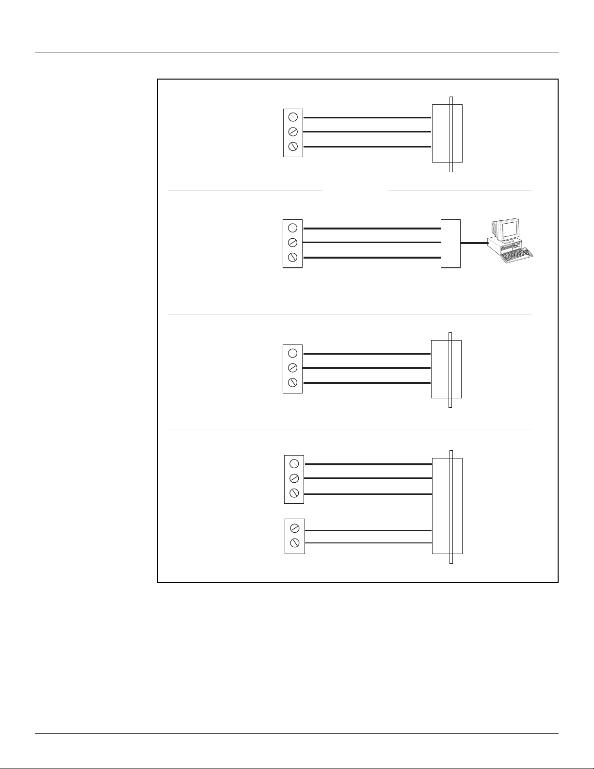
The layout for the RS-232 cable between the PC and the Tank Gate Interface is shown in the
following illustrations.
Varec, Inc. 13
Page 24
TANK GATE
J7
PC
COM0
(RS-232)
TXD
RXD
GND
2
3
5
DB9 Female
Pin Signal
2
3
5
RXD
TXD
GND
NOTE! Signals on RS485 / RS232 converter may have different designations.
Refer to OFM manual for the converter for more information.
A
B
GND
TANK GATE
R5485 / R5238
Converter
J6
PC
A
B
GND
COM1
(RS485)
TANK GATE
J6
PC
COM1
without RTS / CTS
(RS-232)
TXD
RXD
GND
2
3
5
DB9 Female
Pin Signal
2
3
5
RXD
TXD
GND
TANK GATE
J6
DCE
COM1
with RTS / CTS
(RS-232)
TXD
RXD
GND
3
2
5
DB9 Male
Pin Signal
2
3
5
RXD
TXD
GND
8
7
RTS
CTS
J7
78RTS
CTS
Hardware Tank Gate Interface
14 Installation and Operations Manual
Figure 2-14: COM1 Cable without RTS/CTS
Note COM1 is not available on the 8315 Tank Gate Interface.
Page 25
8315 TGI 8215 L&J Tankway Communications Interface Module
3 8215 L&J Tankway Communications Interface Module
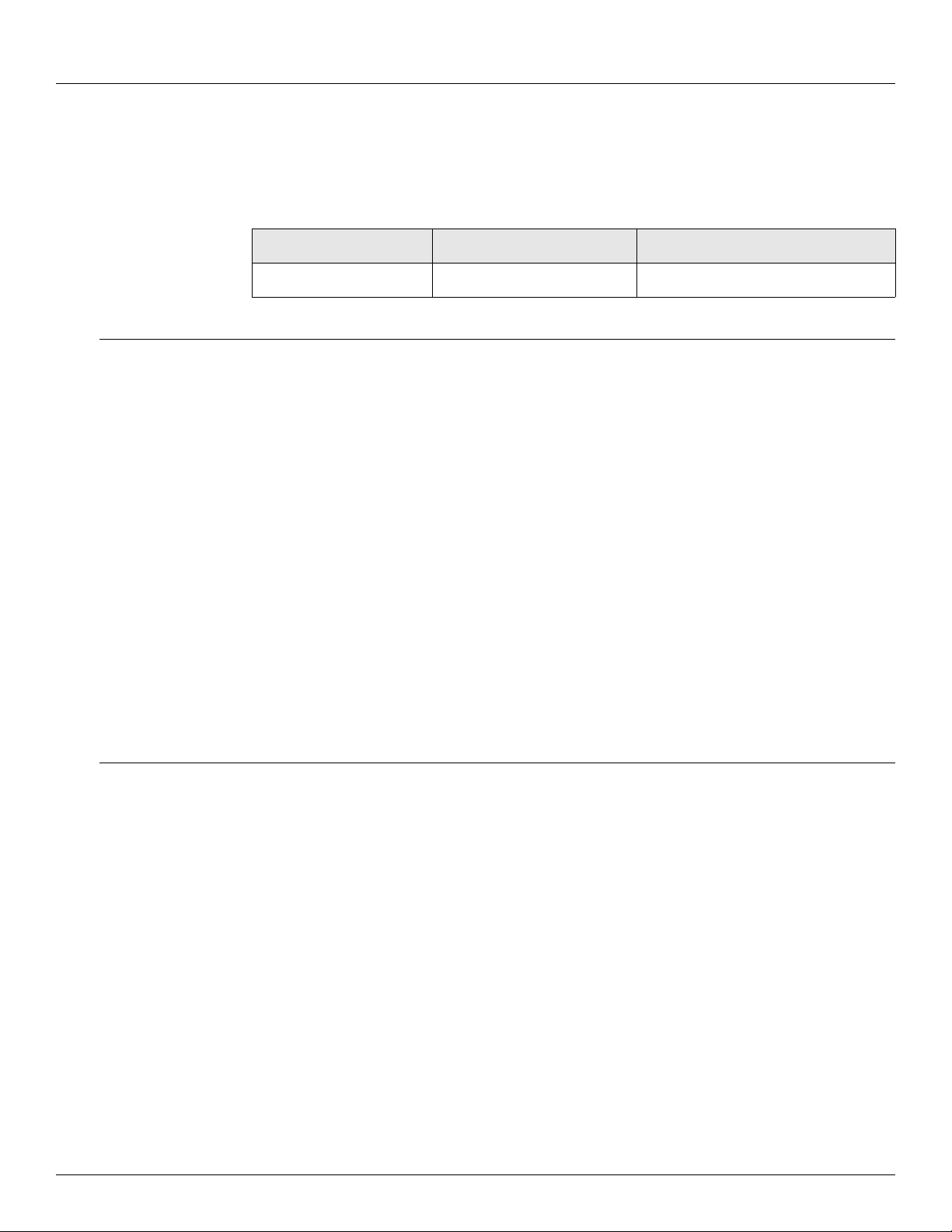
This communications interface module is the processing card that mounts on the TankGate
Interface (TGI) motherboard. The firmware installed on this card determines which protocol is
provided.
Firmware Version Protocol Software Blocks
LJGT1_11 L&J Tankway See section 5 on page 41
3.1 Features
• Supports up to 50 tanks
• Communicates using L&J Tankway protocol
• Interfaces to L&J Tankway compatible Tank Gauge transmitters
• ANSI/IEEE surge protection
The 8315 Tank Gate Interface uses L&J Tankway to communicate. There are a number of
transmitters that are compatible, including:
3.2 Description
• L&J MCG 1000
• L&J MCG 1200
• L&J MCG 1500
• L&J MCG 2000
Note The 8315 Tank Gate Interface uses the 8215 communications module.
The 8215 communications module requires an external +48VDC power supply. It is also
possible to use the +48VDC power supply of the TankGate to power the tank gauge
transmitters, if there are fewer than 15 devices.
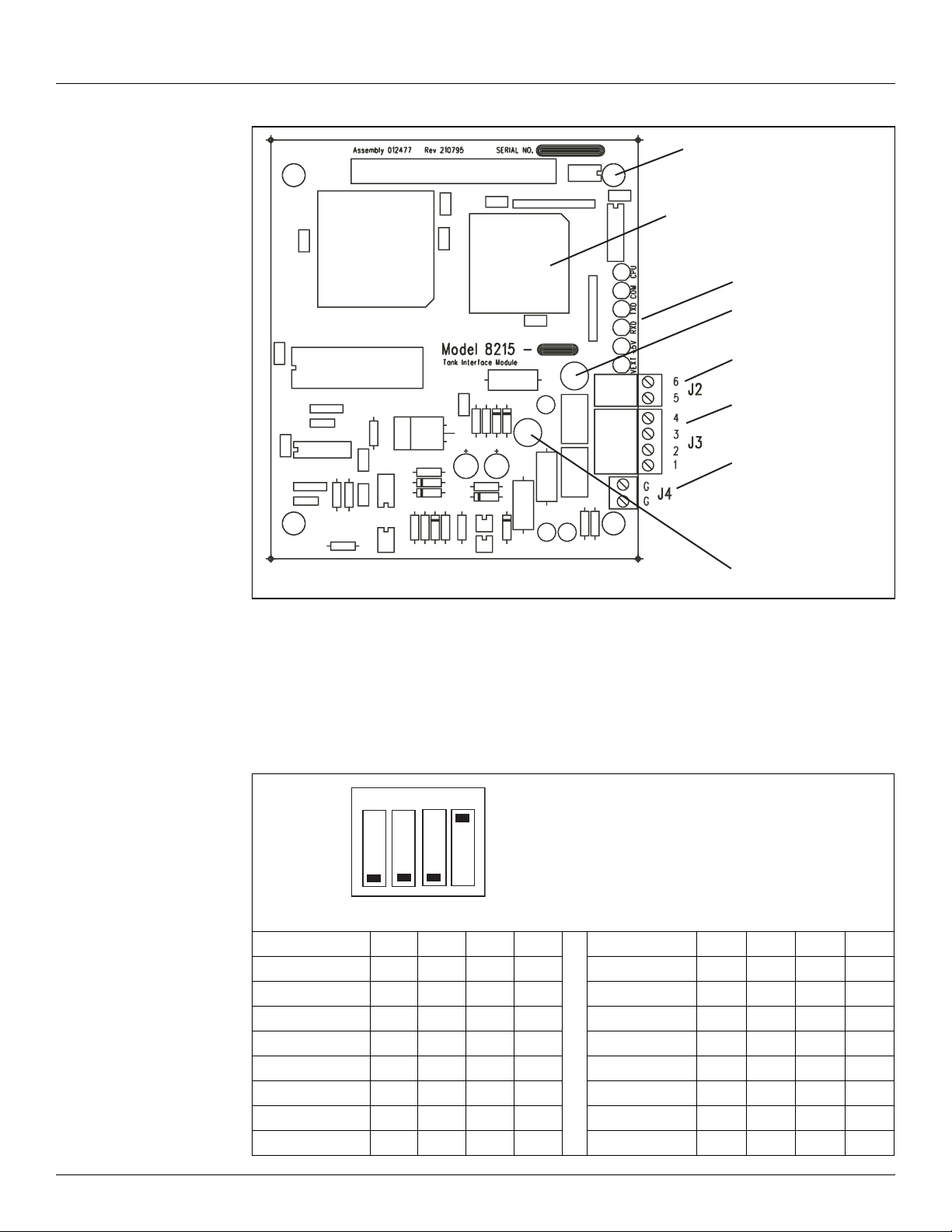
The components of the 8215 are illustrated in the following figure. This section explains how
to connect field wiring and to configure jumper settings.
• Unit ID DIP Switch (SW 1)
• LED Indicators (D1 - D5, D14)
• +48V Line fuse (1A 250V TR5) (F1)
• External Power Connector (+48V) (J2)
• Surge/Shield ground connector (J4)
• Field Wiring termination block (J3)
Varec, Inc. 15
Page 26
8215 L&J Tankway Communications Interface Module Tank Gate Interface
Field wiring
terminal block (J3)
LED indicators (D1 – D6)
Surge/Shield
ground connector (J4)
External Power Connector
(+48 - 65 VDC) (J2)
+48-65 VDC power fuse
(1 A 250V TR5) (F1)
ID DIP Switch (SW1)
Transmit Line Fuse
(63 mA 250V TR5) (F2)
Firmware
Address 1 Shown
CLOSED
OPEN
1234
3.2.1 ID DIP Switch (SW1)
Figure 3-1: L&J Tankway Tank Gate Interface Module
The dip switch is used for setting the ID number (1-14). The ID is a binary number representing
the address of the 8317 TGI.
Table 3-1: ID DIP Switch settings
Binary 8 4 2 1 Binary 8 4 2 1
Switch # 1 2 3 4 Switch # 1 2 3 4
Address 1 o o o c Address 8 c o o o
Address 2 o o c o Address 9 c o o c
Address 3 o o c c Address 10 c o c o
Address 4 o c o o Address 11 c o c c
Address 5 o c o c Address 12 c c o o
Address 6 o c c o Address 13 c c o c
Address 7 o c c c Address 14 c c c o
16 Installation and Operations Manual
Page 27
8315 TGI 8215 L&J Tankway Communications Interface Module
3.2.2 LED Indicators (D1-D6)
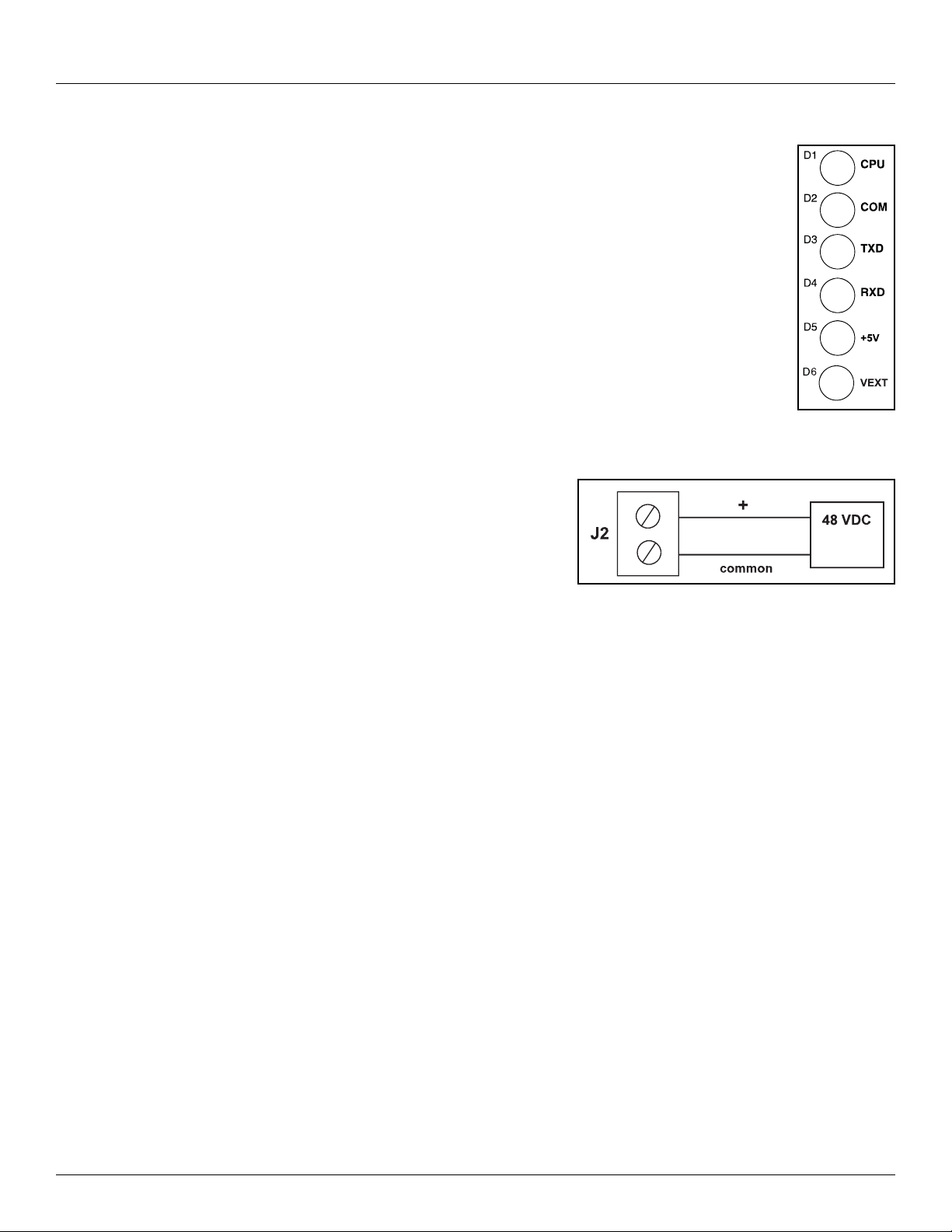
The LED displays indicate the status of the Model 8315’s CPU and
communications. The indicators are identified in the following figure.
• CPU: CPU activity
• COM: Communication between the TankGate and the host computer
• TXD: Transmitting data to tank gauge
• RXD: Receiving data from tank gauge
• +5V: Indicates interface module power
• +VEXT: Indicates external power
Figure 3-2: LED Indicators
3.2.3 External Power Connector (+48V) (J2)
Connect the +48 VDC External Power as shown
below:
Figure 3-3: External Power Connector
3.2.4 Surge/Shield Ground Connector (J4)
Connecting the Surge/Shield ground connector
Caution! This ground connection is important for system safety.
• Connect a 14 AWG copper wire between the ground terminal (J4) and a good earth ground.
Perform this step before connecting ANY other wires.
• Verify that the resistance in this connection does not exceed 1 ohm.
3.2.5 Field Wiring terminal block (J3)
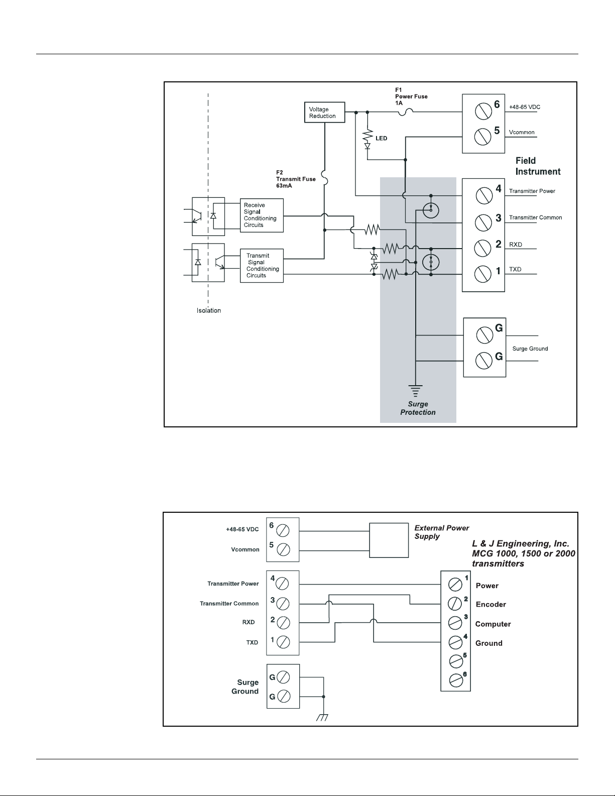
A schematic illustrating the terminal connections of the Model 8315 is shown below:
Varec, Inc. 17
Page 28
8215 L&J Tankway Communications Interface Module Tank Gate Interface
Figure 3-4: Input Circuit
3.2.5.1 Connect the field wiring
Connect the wiring following the diagram below.
Figure 3-5: Application
18 Installation and Operations Manual
Page 29
8315 TGI Software Description
4 Software Description
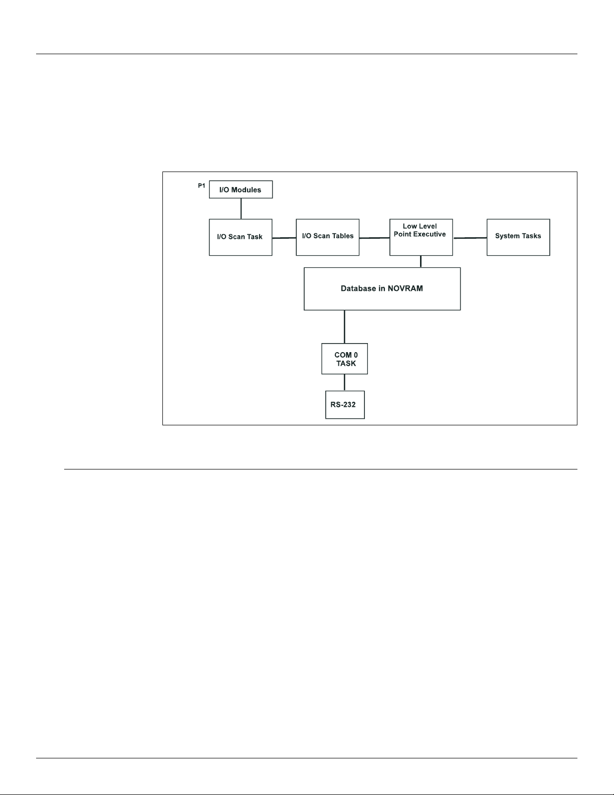
The Tank Gate Interface software platform is based on a real-time, multi-tasking operating
system. The software consists of I/O scanning functions for data acquisition, a database/
database manager and communication functions for data transfer.
Note COM1 is not available on the 8315 Tank Gate Interface.
Figure 4-1: Software Block Diagram
4.1 Software Features
4.1.1 Real-Time / Multitasking Executive
The operation of the Tank Gate Interface is based on a highly reliable, field-proven real-time
multitasking executive. It provides task switching based on real-time events and interrupts,
message passing and task priorities. Its capabilities also include timed suspension of tasks,
queue handlers and interrupt processing tasks.
4.1.2 Real-Time Clock
Integral to the real-time executive is the system’s real-time clock. All timed events of the Tank
Gate Interface are coordinated by this clock. In addition to the real-time executive interaction,
all field data scanning is coordinated by the real-time clock.
4.1.3 Automatic Fault Recovery
The Tank Gate Interface has a watchdog timer that is periodically strobed by the microprocessor.
Should the processor suffer a lapse due to hardware or software failure, the watchdog timer will
time out and the Tank Gate Interface will then be reset and normal operation will resume.
Varec, Inc. 19
Page 30
Software Description Tank Gate Interface
4.1.4 Communications
There are two communications tasks - one for each of the communication channels. COM ports
0 and1 are used to interface to external devices or host systems. Refer to the Hardware Chapter
for the location of these ports.
Note COM1 is not available on the 8315 Tank Gate Interface.
COM0 and COM1
COM 0 and 1 can be configured for communications to Host systems using a variety of
protocols. For COM 0 and 1 the communication interfaces include the following:
• RS-485 for use in multi-drop configurations or long cable runs (or both)
• RS-232 for flexibility in configuring other types of communications links such as radio and
fiber optic interfaces
• RTS/CTS lines are available for hardware handshaking.
4.1.5 Protocols
The Tank Gate Interface is fully compatible with FuelsManager® software. It is also compatible
with a variety of other Host systems including through Modbus protocol.
• RS-485 for use in multi-drop configurations or long cable runs (or both), with an RS232-
to-RS485 converter.
• RS-232 for flexibility in configuring other types of communications links such as radio and
fiber optic interfaces.
The default communication settings for the COM ports are as follows:
COM Port Protocol Baud Rate Data Bits Parity Stop Bits
COM0 RTU Slave or Modbus
- Auto-sensing
COM1 Modbus 9600 8 N 0
9600 8 N 0
Note COM1 is not available on the 8315 Tank Gate Interface.
4.1.6 Data Scanning Task
The Data Scanning Task is dedicated to the scanning of field input data from tank gauges. The
input data is stored in arrays that are subsequently accessed by the Point Executive.
4.1.7 Database Manager
The Database Manager is a collection of programs and data. The Database Manager allows the
Tank Gate Interface system executive to access data from the database in an organized and
program-independent manner. It resides in non-volatile RAM.
The Database Manager also contains a Database Dictionary. This dictionary describes how the
database is organized and also provides information describing how data should be presented
to the operator.
After power-up or system reset, a CRC verification of each point in the database is performed.
If the CRC does not have a match for the point, then it is disabled and a flag is set indicating
that the point is invalid.
20 Installation and Operations Manual
Page 31
8315 TGI Software Description
4.1.8 System Tasks
System tasks include the Calendar Task, which manages Time and Date functions. Other system
tasks include utility routines for checksum calculations, diagnostics, start-up and initialization.
4.1.9 Tank Gate Interface Software Blocks
The user can configure pre-defined subprograms known as Software Blocks. These software
blocks program the Tank Gate Interface to perform various tasks, such as scaling an analog
input value, or scanning level, temperature and status information from a tank gauge. Various
software blocks are available depending on the communication module. Each Software Block
contains all the logic, constants and data to perform a particular function. Every system function
of the Tank Gate Interface is accessible via a Software Block. The user only has to add Software
Blocks using ViewRTU and then configure a few parameters in order to perform a desired
function.
4.2 Database Organization
Points are the individual instances of software blocks. Examples include Whessoe Varec 1900
(MSTX) and SCALER points. In both cases the user configures the Config parameters and is
provided real time data through the Dynamic parameters.
4.2.1 Point Format
Data parameters in the Tank Gate Interface are addressed using a “Type.Number.Parameter”
format. For example, “MSTX.02.Level” refers to MSTX Tank Gauge #2’s IEEE floating point level.
This format and corresponding fields are described below.
The TYPE field represents the Point Type. There are many different point Types in the Tank Gate
Interface, referred to generically as Tank Gate Interface Software Blocks. Some of the point types
include the COM (Communications), SYS (System), MSTX (MSTX Tank Gauge) point types. Each
Type performs a different function.
The NUMBER field represents the instance of the point type. For example, the AI point may have
up to 32 instances, which are addressed using the NUMBER field. Each instance shares the same
data structure definition, yet each point has unique data values. In the case of the AI software
block, each point manages a single input channel.
The PARAMETER field represents the items in the data structure of the point type. Examples of
parameters include Value, Status, PntRef and RawValue. This field is explained in greater detail
in the following section.
4.2.2 Parameter Description
Each parameter is defined by its Parameter Class and Data Type. The following subsections
describe Parameter Classes, Parameter Data Formats and Common Parameters.
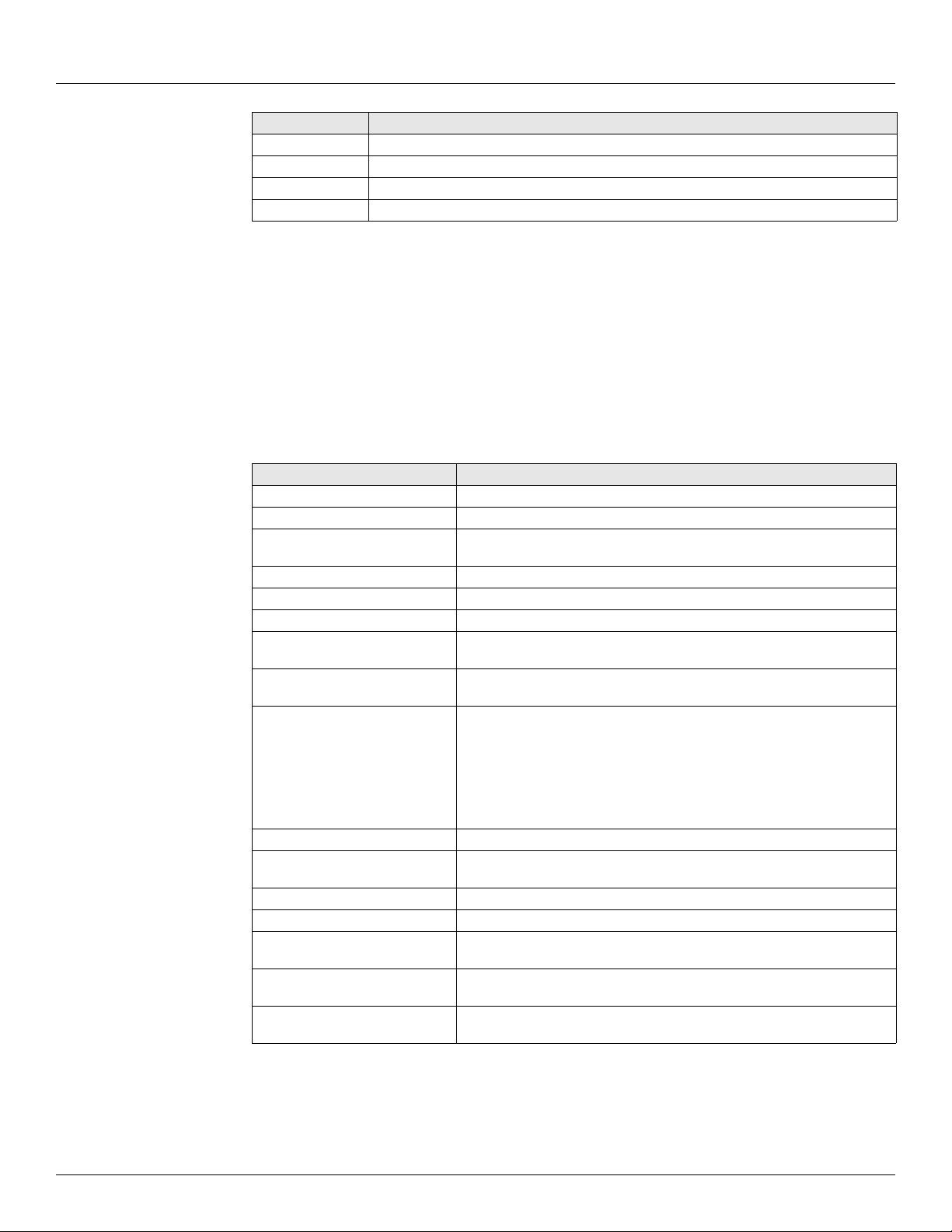
Parameter Classes
Each parameter, such as Value or Channel, is classified as one of the following classes:
Parameter Class Description
Config Configuration parameters such as channel numbers, tags, descriptions, ranges,
Dynamic Real-time data such as the value or the status. Dynamic data is calculated or
Varec, Inc. 21
operating modes, point references, constants for formulas and timing information.
measured during point execution scans, which occur every 250 msec.
Page 32
Software Description Tank Gate Interface
Parameter Class Description
Command Output command data
Constant Weights & Measures parameter
Scratch Temporary data that is typically hidden from the user
System System data (should not be changed by the user)
The user-related parameters are the Config, Command and Dynamic parameters. These
parameters are available in the Edit Point window of ViewRTU. The remaining parameters are
internal to the Software Block.
Note ViewRTU inserts default values for the Config parameters when the point is first
defined. It is usually only necessary to fill in a few configuration parameters, such as channel numbers, to configure references and to configure links to other points.
Parameter Data Formats
Data is stored in the Tank Gate Interface as one of the following formats:
Data Format Description
Byte 8-bit value (-127 to 128)
Unsigned Byte 8-bit value (0 to 255)
Coded Unsigned Integer representing a digital state such as ‘On,’ ‘Off,’
Integer 16-bit value (-32766 to 32767)
Unsigned Integer 16-bit value (0 to 65535)
IEEE floating point 32-bit value with mantissa and exponent
Time Unsigned Long Integer representing the number of milliseconds since
Tag ASCII character strings, variable in length. Used for Tag and Description
Point Reference Reference to a point parameter. Format is TYPE.NUMBER.PARAM where
‘Open,’ ‘Closed,’ etc.
Jan. 1, 1970.
parameters
TYPE is AI, DI, DO, etc.
NUMBER is point number, 0-255
PARAM is the parameter of interest, such as Value or Command.
example: AI.00.Value
Unsigned Long Integer 32-bit value (0 to 4,294,967,295)
Pointer 32-bit value representing a pointer to another parameter or memory
Long Integer 32-bit value
Integer (Hex format) Integer in Hex (0x0000 to 0xFFFF)
Time HH:MM:SS Unsigned Long Integer representing the number of milliseconds since
Time MM/DD/YY Unsigned Long Integer representing the number of milliseconds since
Unsigned Long Integer (Hex
format)
location.
midnight.
Jan. 1, 1970.
Unsigned Long Integer in Hex (0x00000000 to 0xFFFFFFFF)
Common Parameters
The following parameters are found in almost all point types. These parameters are described
below:
22 Installation and Operations Manual
Page 33

8315 TGI Software Description
PntCheckSum Parameter
The PntCheckSum is a CRC-16 checksum of the Configuration Parameters of a point. Most
points have the PntCheckSum parameter; a few like the CLK (Clock) Point, DIAG (Diagnostics)
Point, and the register points (BREG, IREG, and DREG) do not. Any time a Configuration
Parameter is changed, the Tank Gate Interface re-calculates the checksum. The PntCheckSum is
used at initialization to validate each point in the database.
PntStatus Parameter
The PntStatus parameter gives information about point execution. Refer to the information
provided for each Software Block about the particular use of the PntStatus parameter.
Elapse Parameter
The Elapse parameter usually indicates the time of the last point execution. It is used as the
basis for automatic Change of State notifications.
Value Parameter
The Value parameter indicates the real-time value of the point. In the case of DI points, the Value
represents a Coded value (i.e., On, Off, Opened, Closed, etc.) AI points represent the Value in an
IEEE floating point format. In most cases, the Value parameter is one of the most important
parameters for a point.
Level & Temp Parameters
The Level & Temp parameters indicate the real-time tank level and temperature of the tank
gauge point. There are many Software Blocks available in the Tank Gate Interface associated with
tank gauge communications, including Software Blocks for every major tank gauge
manufacturer.
4.3 Gathering Point Data
For Host to Tank Gate Interface communications, there are two primary methods for gathering
point data. These methods are listed below:
4.3.1 Standard Request-Response Format
The Host issues scan requests, and the Tank Gate Interface responds with the data.
The Scan method has the advantage of being deterministic, the response time to a particular
request will always be the same.
This method has the limitation that if there are many points defined in the Tank Gate Interface,
it often takes several requests to obtain all of the data. Most of the time data has not changed
since the last request, so this results in inefficiencies in update times. This situation is often the
case in systems where there are many digital points that do not change frequently.
4.3.2 Change of State Fo rmat
The Ho st issues scan requests based on a Cha nge o f State condition . Some systems refer to this
as Event Mode. The Tank Gate Interface keeps track of the items that have changed since the
last Host request. The Host can issue a single request of ‘tell me what has changed since my last
request.’ The Tank Gate Interface will respond with the results, which include addressing
information about the data. In a typical system, this results in a significant improvement in the
throughput rate for data.
Varec, Inc. 23
Page 34
Software Description Tank Gate Interface
When FuelsManager is the Host system, the Change of State method has the advantage of being
very efficient. Only the data that has changed is reported. Change of State is not available when
using Modbus.
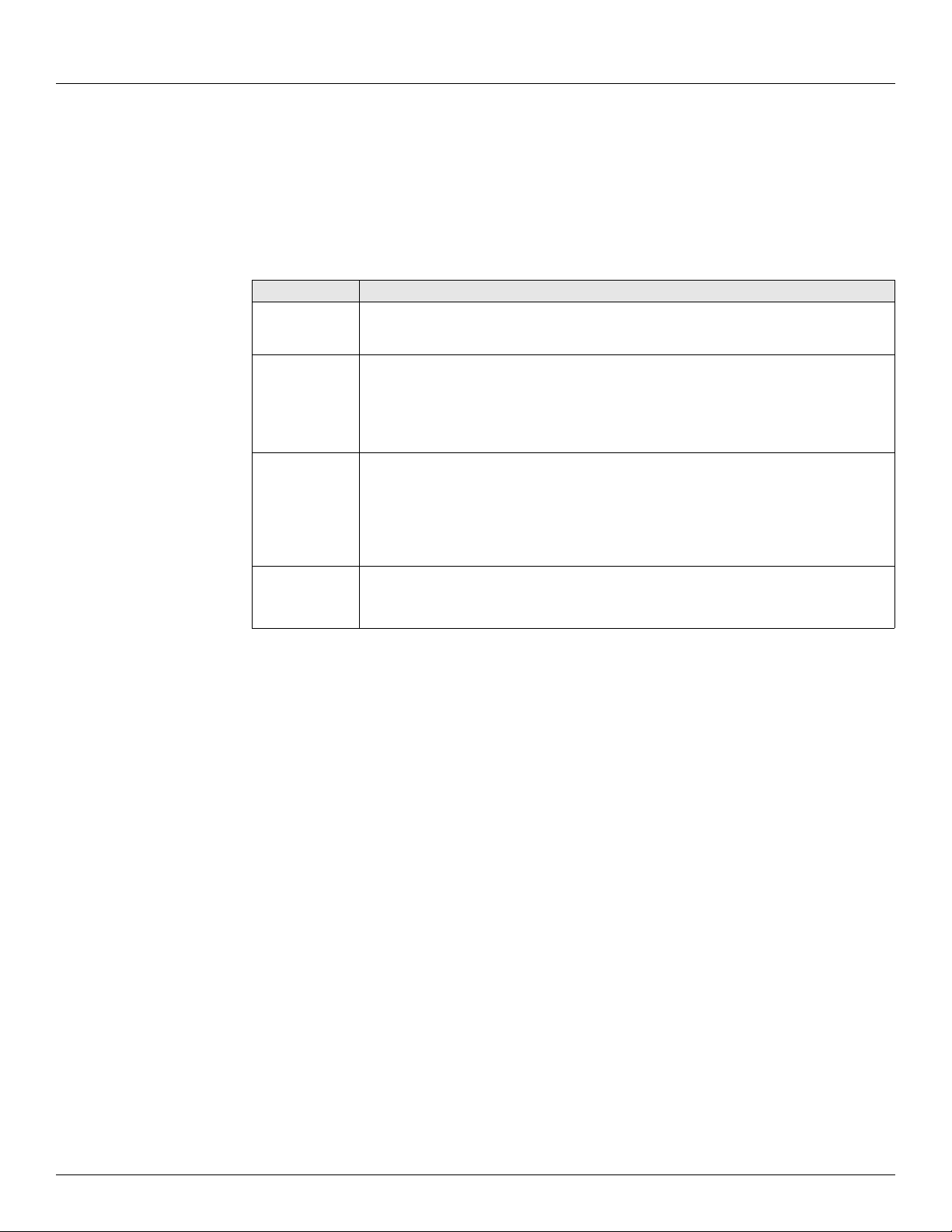
4.3.3 Change of State-Related Parameters
In order to support the Change of State method, many points have additional configuration
parameters included.
Parameter Description
Value One of the parameters which will be returned to a Change of State request by the Host.
Most Software Blocks are designed so that the Value parameter is the main parameter
of interest.
Report Is used for Change of State processing only
Causes automatic notification to the Host (in response to a Change of State Request)
when the Value Changes State.
Valid values are High, Low or No. Report = No disables notification.
Points with Report = High have higher priority than points with Report = Low.
Maxtime Is used for Change of State processing only
Specifies the maximum time (in secs) between automatic Change of State data being
sent to the Host in response to a Change of State Request.
When the Maxtime period expires, the Value to is forced appear as if it has changed
even if is has not, ensuring that data is sent to the host periodically.
Setting Maxtime to 0 disables this option. The maximum is 255 seconds.
Deadband
LevelDeadband
TempDeadband
Affects the Change of State processing. It allows users to filter out insignificant
changes, freeing the communications link to send other data.
Note Not all Host protocols support the Change of State method. The RTU Slave protocol
used with FuelsManager supports either method.
Note The Modbus protocol is Scan-based. Therefore, the Report and Maxtime parameters
have no meaning.
4.3.4 Modbus Communications
Some versions of the Tank Gate Interface are capable of communicating with Modbus
compatible devices with both Modbus Masters and Slave devices. The Tank Gate Interface is
flexible, allowing communications with devices that strictly comply with the Modicon Modbus
protocol, as well as devices with more advanced Modbus implementations such as Honeywell’s
APM-SIO.
The Modbus Slave protocol handler responds to read and write requests from a Modbus master
system. A detailed description of the Modbus Slave protocol handlers follows.
Modbus Slave
The Modbus Slave protocol handler is enabled by setting the Protocol parameter of a COM point
to Modbus Slave. COM 0 of the Tank Gate Interface is auto sensing. If a Modbus Master requests
data from the Tank Gate Interface, the Tank Gate Interface will automatically detect that Modbus
is being used and invoke the Modbus Slave protocol handler. The Modbus Slave protocol handler
responds to requests from Modbus masters. A MODGW point is automatically created to provide
user access to the operation of the protocol handler. The MODGW point also provides dynamic
information about the communications requests from the Modbus master.
24 Installation and Operations Manual
Page 35
8315 TGI Software Description
The Modbus Slave protocol handler is flexible, allowing the user to set options for handling
several aspects of Modbus communications. The Modbus Slave uses the GWBLK Gateway Block
as a lookup table for data addresses.
The Gateway Block allows the user to specify data address and point reference combinations.
This allows the Tank Gate Interface to be used with an existing system that is already configured.
The user defines a GWBLK point and specifies which parameter in the Tank Gate Interface will
be used for a particular address. When a request from a master is received, the Modbus Slave
protocol handler will first search for any GWBLK points and determine if the data address of the
request is specified in one of the GWBLK points. If the data address is contained in a GWBLK
point, then the corresponding point reference is used to provide the data for the reply to the
master.
COM 0 will automatically sense whether the host system is ViewRTU or a Modbus Master. The
communications parameters for COM 0 are 9600 baud, 8 data bits and No Parity. When
switching between ViewRTU and Modbus communications, it is necessary to wait 60 seconds for
the current protocol to time-out. The Tank Gate Interface will go back to the auto sensing mode
and wait for a request. When a request is received, the Tank Gate Interface will determine if the
request is from ViewRTU or a Modbus Master. If the Tank Gate Interface has problems switching,
press the Reset button and this will force the Tank Gate Interface back into the auto sensing
mode.
Note COM 1 (if available) is always a Modbus Slave. The communications parameters for
COM 1 are 9600 baud, 8 data bits and No Parity. COM1 is not available on the 8315 Tank
Gate Interface
Note The Tank Gate Interface uses the ID switch in determining to which address on the
communications bus to respond.
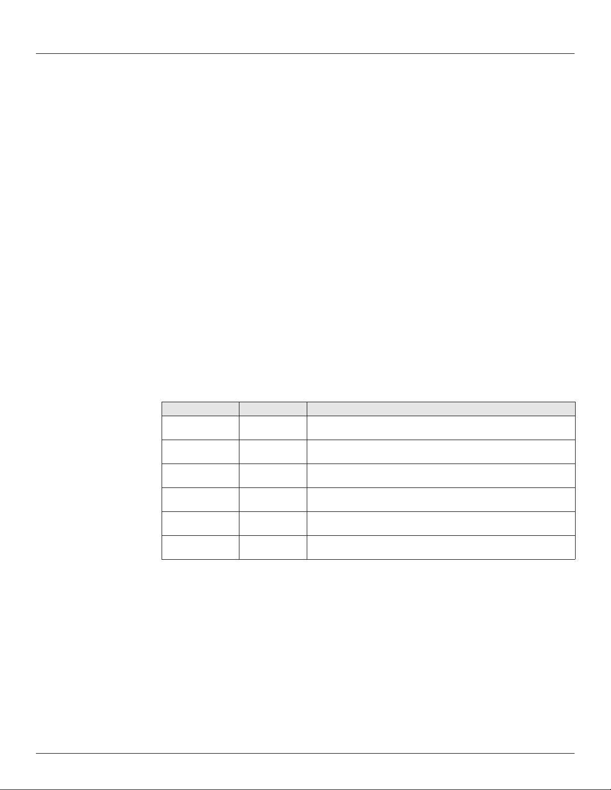
Tank Gate Interface responds to the following Function Codes:
Function Code Description Comments
3 Read Output
Register
4 Read Input
Register
5Force Single
Output Status
6Preset Single
Register
15 Force Multiple
Outputs
16 Preset Multiple
Registers
FC 3 and FC 4 are treated the same. Use either FC 3 or FC 4 to read
data from the Tank Gate Interface
FC 4 and FC 6 are treated the same. Use either FC 5 or FC 6 to write
data to the Tank Gate Interface
FC 15 and FC 16 are treated the same. Use either FC 15 or FC 16 to
write multiple registers to the Tank Gate Interface
There are two methods for data addressing within the Tank Gate Interface
• The Tank Gate Interface has a fixed Modbus Map of selected parameters
• Gateway Block (GWBLK) software blocks can be configured to set the data address
Varec, Inc. 25
Page 36
Software Description Tank Gate Interface
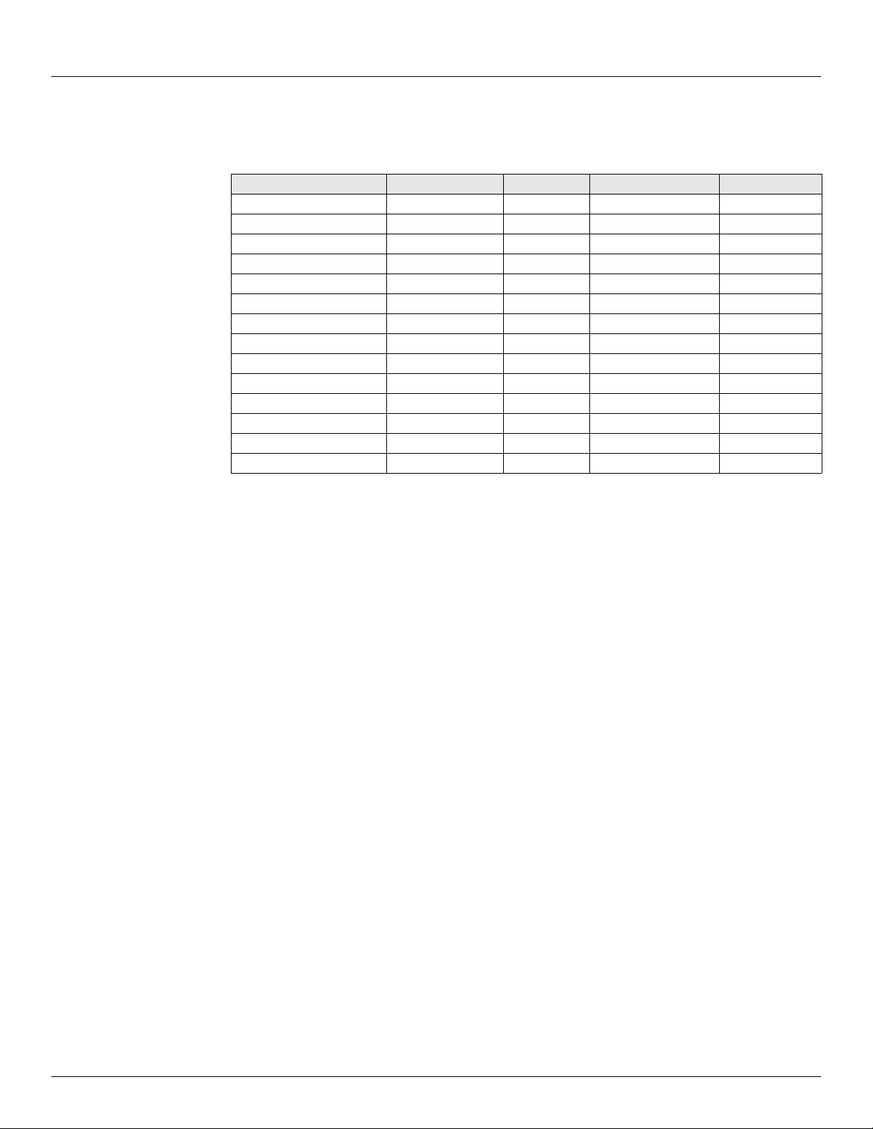
4.3.5 Fixed Modbus Map
For each version of the Tank Gate Interface, there is a fixed map of data registers. A partial
example is shown below:
Address Type Number Parameter Data Type
5000 MSTX 0 Command CODED
5001 MSTX 0 Level REAL
5003 MSTX 0 Temp REAL
5005 MSTX 0 Value REAL
5007 MSTX 0 Status HEX
5008 MSTX 0 PntStatus IHEX
5009 MSTX 0 Elapse TIME
5011 MSTX 1 Command CODED
5012 MSTX 1 Level REAL
5014 MSTX 1 Temp REAL
5016 MSTX 1 Value REAL
5018 MSTX 1 Status HEX
5019 MSTX 1 PntStatus IHEX
5020 MSTX 1 Elapse TIME
Table 4-1: Fixed map of data registers
4.3.6 GWBLK method
The GWBLK is the preferred means to address data in the Tank Gate Interface. The GWBLK has a
great deal of flexibility. Data can be scaled, or grouped using the GWBLK. The Gateway Block
(GWBLK) allows the user to specify data address and point reference combinations. This allows
the Tank Gate Interface to be used with an existing system that is already configured. The Tank
Gate Interface can be tailored to meet the needs of the Host. In some cases, the Host system
may have some constraints in the use of its Modbus scanner that make it necessary to use a
GWBLK. In this mode, the user defines a GWBLK point and specifies which database parameter
will correspond to a particular data address. When a request from a master is received, the
Modbus Slave protocol handler will first search for any GWBLK points and determine if the data
address of the request is specified in one of the GWBLK points. If the data address is contained
in a GWBLK point, then the corresponding point reference is used to provide the data for the
reply to the master. If the data address is not in any GWBLK point, then data will be read using
the prevailing Address Mode.
The Gateway Block (GWBLK) allows the user to specify data address and point reference
combinations. The GWBLK acts as a lookup table for data items in the Tank Gate Interface. The
user defines a GWBLK point and specifies which database parameter will correspond to a
particular data address. When a request from a master is received, the Modbus Slave protocol
handler will search for any GWBLK points and determine if the data address of the request is
specified in one of the GWBLK points. If the data address is contained in a GWBLK point, then
the corresponding point reference is used to provide the data for the reply to the master.
The procedure for using the GWBLK is given below:
• Add a GWBLK point. Depending upon the addressing requirements of the host system, it
may be necessary to add additional GWBLKs.
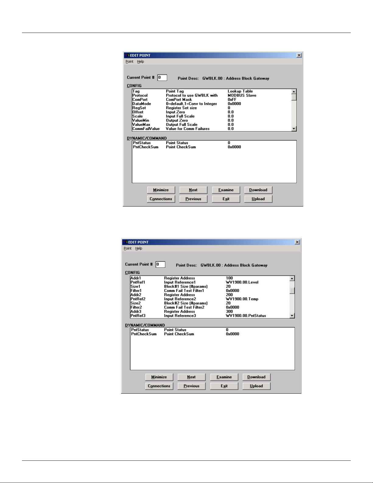
• Configure the GWBLK by setting the Address, PntRef and Size parameters to the parameters
of interest in the Tank Gate Interface. Refer to the following examples:
26 Installation and Operations Manual
Page 37
8315 TGI Software Description
Figure 4-2: Adding a GWBLK point in View RTU
Figure 4-3: Configure the GWBLK in View RTU
Varec, Inc. 27
Page 38
Software Description Tank Gate Interface
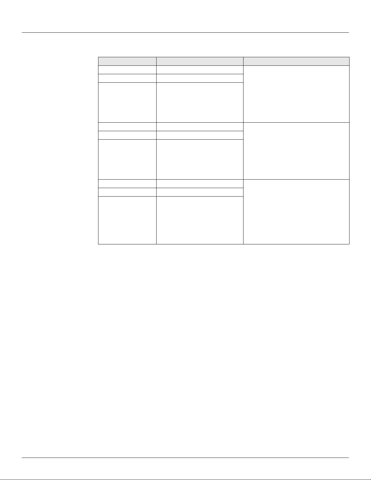
In this example, the Modbus register map is configured according to the following table:
Data Address Parameter Comments
100-101 MSTX.00.Level Level is in IEEE Floating point format.
102-103 MSTX.01.Level
104-105
.
.
.
138-139
200-201 MSTX.00.Temp Temperature is in IEEE Floating Point
202-203 MSTX.01.Temp
204-205
.
.
.
238-239
300 MSTX.00.PntStatus PntStatus is in Integer format.
301 MSTX.01.PntStatus
302
.
.
MSTX.02.Level
.
.
.
MSTX.19.Level
Format.
MSTX.02.Temp
.
.
.
MSTX.19.Temp
MSTX.02.PntStatus
.
.
.
.319
.
.MSTX.19.PntStatus
Table 4-2: Example Modbus register map
28 Installation and Operations Manual
Page 39
8315 TGI Software Description
4.4 Common Software Blocks
This section describes Software Blocks included with the base unit of the 8315 TGI.
4.4.1 Clock (CLK)
The Clock point provides access to the System Clock. Standard time format is in the
form of MM/DD/YY HH:MM:SS.
Parameters
The database parameters used by the CLK point are listed and described below:
Configuration Parameters Function
TZ Time Zone string
Dynamic Parameters Function
SysTime System Time in the form MM/DD/YY HH:MM:SS. Writing to this value will
change the system time
SysTicks Time if “ticks” format. Ticks are incremented every 10 msec, with the initial
timezone Time zone relative to GMT. The timezone is entered in seconds.
daylight Daylight Saving Flag
value of 0 equal to Jan. 1, 1970 at 00:00:00.
Example: Eastern Time Zone = 18000; Pacific = 28800
4.4.2 Communications (COM)
The Communications point reports the status and controls the operation of the
communications interfaces. COM points are automatically created by the system at
initialization.
Parameters
The database parameters used by the COM point are listed and described below:
Configuration Parameters Function
Protocol Protocol handler assigned to the ComPort. Valid values are:
Disabled
RTU Slave
Modbus Slave
TSU Slave
The defaults are:
COM 0: RTU Slave - 9600 Baud
COM 1: Modbus Slave- 9600 Baud
Mode The Mode parameter is used in conjunction with the Protocol. Different
protocols will use the Mode in different ways, depending on the needs of
the protocol.
ComPort Communications Port number. Valid values are 0-3. You should never
modify the ComPort parameter.
Varec, Inc. 29
Page 40
Software Description Tank Gate Interface
Configuration Parameters Function
BaudRate Baud Rate for communications to either the Host or Slave system. Valid
values are: 1200, 2400, 2400, 9600, 19200. Changing the BaudRate
parameter will immediately change the configuration of the ComPort.
The default is 9600.
ComParams Defines the number of data bits and the parity used by the com port.
Examples include:
8O - 8 Data Bits Odd Parity
8E - 8 Data Bits, Even Parity
8N - 8 Data Bits, No Parity
7O - 7 Data Bits, Odd Parity
7E - 7 Data Bits, Even Parity
7N - 7 Data Bits, No Parity
TI - TIWAY
The default is ‘8N’.
TimeOut Time in seconds that indicates a time-out of communications. If no Host or
Slave communications is received for the length of time specified by the
TimeOut, the CommStatus parameter will indicate Off Line and
communications failure processing will take place.
ErrCheck Error checking used by the protocol. Valid values are:
LRC - Longitudinal Redundancy Check
CRC - Cyclical Redundancy Check
RespDelay Time in milliseconds for which the 8303 TGI will delay a response to the
Host. The default is 50 msec.
SynchMax The SynchMax is used by some slave protocols for autosynchronization of
DirectPort The DirectPort is used then the Protocol is set to Direct.
the BaudRate. The SynchMax is used to determine if the BaudRate is correct.
If the SynchMax is zero, then no synchronization is attempted.
Dynamic Parameters Function
CommStatus Coded variable indicating the On-line/Offline status of the COM point.
State Current state of the message being sent/received.
Command Current command being processed.
Status Status if the last message.
CommErrors The number of communication errors.
NumTrans The number of transactions.
Elapse Time of the last Change of State.
PntCheckSum CRC-16 Checksum of point's static Configuration Parameters.
Application
The COM point controls the operation of Host and Slave communications. The Baud Rate,
Communications Parameters and Protocol may be changed by assigning values to the
appropriate parameter. Each Com port is independent of the other and completely flexible in its
use.
For example, you may configure the system to communicate with a single host redundantly
using the same protocol. Alternatively, the 8300 series Tank Gate Interface can communicate to
different hosts using different protocols, allowing the 8300 series Tank Gate Interface to act as
a bridge. Other options include assigning one COM point to communicate with a Slave device
while communicating to a Host system on the other.
30 Installation and Operations Manual
Page 41
8315 TGI Software Description
4.4.3 Floating Point Register (FPREG)
The Floating Register point provides four bytes of storage in IEEE floating point
format. It is often used for inter-point communications where no other means is
provided.
Parameters
The database parameters used by the FPREG point are listed and described below:
Configuration Parameters Function
Tag Point tag
Dynamic Parameters Function
Value1 through Value50 Real (4 bytes) value
PntStatus Integer HEX value indicating status of point. Values are:
0x0001: Gauge Not Responding. The first time the gauge does not respond,
the 0x8000 bit is set. On the second try, the 0x01 bit is set.
0x0002: Data Invalid (General Data Error)
0x0004: Bad Level
0x0008: Temp OverRange
0x0010: Temp UnderRange
0x0020: A/D Error
0x0040: Filtering Level
0x0800: Filtering Temp
Elapse Time of the last Change of State.
PntCheckSum CRC-16 Checksum for point’s static Configuration Parameters.
4.4.4 Emulator (EMU)
The Emulator point allows the to emulate a Whessoe-Varec Model 6820 Tank
Scanning Unit (TSU). This point provides access for level, temperature data, and
gauge status information from any type of tank gauge interface supported by the
8203 Dual RS-485 Communications Interface Module.
Parameters
The database parameters used by the EMU point are listed and described below:
Configuration Parameters Function
Tag The point description can contain 30 bytes of data and can include any
printable ASCII character. Descriptions can be used as information
relevant to any aspect of the point, such as its use, location, operating
information, etc. The default description is set to “EMU.00”.
LevelUnits Specifies the engineering units for the level data.
F: feet, m: Millimeters
M: Meters
I: Inches
P: ft-in-16ths
The LevelUnits need to match the units specified during the gauge setup.
Varec, Inc. 31
Page 42
Software Description Tank Gate Interface
Configuration Parameters Function
TempUnits Specifies the engineering units for the temperature data.
TempUnitsSpecifies the engineering units for the temperature data.
F: Fahrenheit
C: Celsius
The TempUnits needs to match the units specified during the gauge
setup.
DensityUnits Specifies the engineering units for the density data.
DensityUnitsSpecifies the engineering units for the density data.
K: kg/m3
A: API
L=lbs/cu ft
The DensityUnits needs to match the units specified during the gauge
setup.
Offset Specifies the offset to the first address.
PntRef1 - 20 Input point reference for the EMU point to monitor. The PntRef parameter
is set to the Level parameter for the tank gauge point. The temperature
will be read at the same time as the level. The EMU point interfaces tank
gauge interface points:
WV1900 - Whessoe-Varec Model 1900
Dynamic Parameters Function
PntStatus Byte value indicating status of point Values are:
Dynamic ParametersFunction
PntStatusByte value indicating status of point Values are:
0: No error
15: Invalid Type for PntRef
16 Invalid Number for PntRef
17 Invalid Param for PntRef
19: PntRef point does not exist
25: PntRef is not defined
PntCheckSum CRC-16 Checksum for point's static Configuration parameters.
Application
The Emulator point (EMU) provides a communication interface between older tank gauging
system and point blocks within the 8203 Dual RS-485 Communications Interface Module .
Currently, the 8203 Dual RS-485 Communications Interface Module can emulate a Whessoe
Varec Model 6810 Tank Scanning Unit (TSU).
The EMU point associates a tank gauge point with an address to by used by TankView. EMU.0
provides point references for TankView System Addresses 1-50. EMU.1 is associated with
System Addresses 51-100. A EMUGW gateway point is automatically created when the protocol
for a COM point is set to TSU Slave.
32 Installation and Operations Manual
Page 43
8315 TGI Software Description
4.4.5 EMU Gateway (EMUGW)
The EMU Gateway point is used to manage scanning functions for the EMU point.
Statistics are maintained for the communications between the Series 8130 and the
tank gauging software (TankView or System IV). Special firmware is required on the
8203 Dual RS-485 Communications Interface Module to support the emulation
functions.
Parameters
The database parameters used by the EMUGW point are listed and described below:
Configuration Parameters Function
Protocol Protocol to emulate. Valid values are:
TSU Slave
ID Address to respond to
Mode Operational Mode
BaudRate Baud Rate used to communicate with TankView
ComParams Defines the number of data bits and the parity used by the com port.
Examples include:
ID: Address to respond to
Mode: Operational Mode
BaudRate: Baud Rate used to communicate with TankView
ComParamsDefines the number of data bits and the parity used by the com
port. Examples include:
8O - 8 Data Bits Odd Parity
8E - 8 Data Bits, Even Parity
8N - 8 Data Bits, No Parity
7O - 7 Data Bits, Odd Parity
7E - 7 Data Bits, Even Parity
7N - 7 Data Bits, No Parity
The default is ‘8N’.
LevelConvert Determines the units in which the level data will be displayed. F: feet, M:
TempConvert Determines the units in which the temperature data will be displayed. F:
DensityConvert Determines the units in which the density data will be displayed. A: API, L:
Millimeters. If no value is specified, no conversion will be performed.
Fahrenheit, C: Celsius. If no value is specified, no conversion will be
performed.
lbs/cu ft, K: kgs/m3. If no value is specified, no conversion will be
performed.
Dynamic Parameters Function
Message Hex representation of the request sent by the host
Command Current Command
Addr Displays the tank number of the currently selected tank.
Varec, Inc. 33
Page 44
Software Description Tank Gate Interface
Dynamic Parameters Function
LevelRef The reference point for level and temperature data for the tank currently
Flags Hex value representing the operational status
NumRequests Number of requests from TankView or Entis
NumComErrors Number of errors
Elaspe Time of last request
PntCheckSum CRC-16 Checksum for point’s static Configuration Parameters.
requested by TankView
Application
The EMUGW point is automatically created when the TankView (TSU Slave) protocol is initiated.
In order to use the TSU Slave protocol, set the Protocol parameter of the COM point to TSU Slave.
At that time, an EMUGW and an EMU point will be created to provide a user interface for
configuration and control of communications with TankView or System IV. The baud rate and
data link parameters are set in the COM point as well. The default is 9600, 8 data bits, No parity.
The EMUGW point keeps track of the number of requests and number of errors associated with
the EMU Slave protocol. The current tank number (ID) and the point associated with the tank
number (LevelRef) are updated as requests from TankView are processed. The PntRefs correlate
to the SYS ADR parameter in TankView or IDs in System IV.
4.4.6 Gateway Block (GWBLK)
The Gateway Block point is used for compatibility with Modbus Master devices.
Rather, you configure a GWBLK to function as a look-up table. The GWBLK point lets
you specify which point references will respond to data addresses in the request
from a Host. The GWBLK point contains a cross-reference table for database
parameters and data addresses.
Parameters
The database parameters used by the GWBLK point are listed and described below:
Configuration Parameters Function
Tag A Tag can contain 15 bytes of data and can include any printable ASCII
character. Tags can be used to identify points indicating the use of the point
such as “Modbus Slave” or “Register Value1.”
The default tag is set to “GWBLK.00”.
Protocol Protocol that the GWBLK point is used with. Valid values are:
Modbus Slave
ComPort Bit mask to enable address referencing. If a bit corresponding to the com
port, then address referencing is enabled for the channel.
The default is 0xFF (all COM ports).
34 Installation and Operations Manual
Page 45
8315 TGI Software Description
Configuration Parameters Function
DataMode Integer HEX value that controls the data returned to a Modbus Host
0: Use parameter values
0x01: Convert to Integer
0x02: Return 0xFF if the data is invalid.
0x04: Convert to Integer using only the Scale
If the DataMode is 0x01, the PntRef data will be converted to an integer
using the Offset, Scale, ValueMin and ValueMax. If the DataMode is 0x04,
the Scale parameter is used to convert to an integer.
RegSet Register Set size
Offset Input range Offset used for scaling the output to an integer value when
DataMode=1.
Scale Input range Scale used for scaling the output to an integer value when
DataMode=1.
ValueMin Output range Offset used for scaling the output to an integer value when
ValueMax Output range Scale used for scaling the output to an integer value when
CommFailValue Value to set all of the output registers to when there is a communications or
Addr1-10
PntRef1-10
Size1-10
Filter1-10
DataMode=1.
DataMode=1.
other failure. The CommFailValue works in conjunction with the Filter
values. If the PntStatus of the PntRef has bits set that match the Filter, the
reference value is declared invalid and the output value will be set to the
CommFailValue. This mode is overridden by DataMode = 0x02.
Addr1 is the Data Address and PntRef1 is the corresponding database
parameter that will be used for a response. The default Size is 1. See the
discussion below for more detail on the Size parameter.
The Filter is used to determine if the data is valid. The PntStatus of the point
specified by the PntRef is read and if there are bits set that match the Filter,
the source data is considered invalid. The output registers will be set to the
value determined by the CommFailValue.
Dynamic Parameters Function
PntStatus Byte value indicating status of point Values are:
0: No error
pntCheckSum CRC-16 Checksum of point's static Configuration Parameters
Application
The GWBLK point is a look-up table used by the Modbus Slave protocol handler. Up to sixteen
address-point reference pairs may be used per GWBLK point. Multiple GWBLK points may be
used if necessary. The Addr parameter specifies the data address. The corresponding PntRef
parameter specifies the database parameter for the request. The Gateway Block point allows you
to use the 8300 series Tank Gate Interface easily in retrofit applications. It is not necessary to
re-configure an existing HMI or Host system. You can configure the 8300 series Tank Gate
Interface to match the addresses used in the Host system.
When the Modbus Slave protocol handler receives a request, it searches the GWBLK points to
determine if any of the Addr parameters match the request. If a match is found, the data
referenced by the PntRef parameter will be used for the response.
There are three data modes: DataMode=0, which returns the data in the default format, and
DataMode=1, which returns the data in an integer format. DataMode=1 will scale IEEE floating
point data to an integer value, using the Offset, Scale, ValueMin and ValueMax parameters. If
DataMode = 4, the data will be scaled to an integer by multiplying the data value times the Scale
parameter.
Varec, Inc. 35
Page 46
Software Description Tank Gate Interface
The DataMode can also control if the data is changed to 0xFFFF if the data is invalid. The Filter
parameter is compared to the PntStatus of the PntRef parameter. If bits in the PntStatus match
bits in the Filter, the data is considered invalid and the a read from a modbus host will result in
the data being set to 0xFFFF.
When Block Read or Write requests are received, then the way in which the Modbus Slave
protocol handler responds is determined by the Size parameter.
Size Parameter
A range of addresses can be specified by setting the Size parameter. This sets the indexing
mode to Number Indexing, which means that Block Read/Write requests from the Hosts are
handled by stepping through the points number by number. For example, if Addr1 is 100, and
PntRef1 is MSTX.00.RawValue, then a Block Read to address 100 with a length of 8 will return
the values, MSTX.00.RawValue, MSTX.01.RawValue, ... MSTX.07.RawValue. Setting the Size to 1
does not limit the read to 1 parameter, rather it indicates that block operations will be processed
by stepping through points by incrementing the number, starting with parameter specified by
the PntRef.
4.4.7 Integer Register (IREG)
The Integer Register point provides two bytes of storage. It is often used for interpoint communications where no other means is provided.
Parameters
The database parameters used by the IREG point are listed and described below:
Configuration Parameters Function
Tag A Tag can contain 15 bytes of data and can include any printable ASCII
Dynamic Parameters Function
Value Integer (2 bytes) value
character. Tags can be used to identify points indicating the use of the
point.
4.4.8 Modbus Gateway (MODGW)
The Modbus Gateway provides dynamic and statistical information for the
communications between the 8300 series Tank Gate Interface and the Modbus
masters.
Parameters
The database parameters used by the MODGW point are listed and described below:
36 Installation and Operations Manual
Page 47
8315 TGI Software Description
Configuration Parameters Function
ID Slave Address that the Modbus Slave protocol handler will respond to. The
default is to match the Unit Address of the 8300 series Tank Gate Interface.
Mode Operational Mode. The Mode is a hex value, with individual bits controlling
BaudRate Baud Rate for communications to the Host system. Valid values are: 1200,
ComParams Defines the number of data bits and the parity used by the com port. Valid
DetectTime Modbus RTU Mode character timer (in 1/100s of a second).
various aspects of the operation of the Modbus Slave protocol handler. The
bits have the following meanings:
0x01 – Set Param Indexing mode
0x02 - Integer Swap mode
0x04 – Swap CRC bytes
0x08 - ASCII mode
0x20 – Wonderware Mode
0x80 - Ignore any trailing nulls in the request
The default is 0.
2400, 2400, 9600 and 19200. Changing the BaudRate parameter will
immediately change the configuration of the ComPort.
values include:
8N - 8 data bits, No parity
8O - 8 data bits, Odd parity
8E - 8 data bits, Even parity
7O - 7 data bits, Odd parity
7E - 7 data bits, Even parity
The default is ‘8N’.
Dynamic Parameters Function
Message Current request message, displayed in hex format.
Command Current command. Values include:
1 - Read Output Status
2 - Read Input Status
3 - Read Output Registers
4 - Read Input Registers
5 - Force Single Coil
6 - Preset Single Register
15 - Force Multiple Coils
16 - Preset Multiple Registers
Addr Data Address for current request.
Elapse Time of the last request from the master
PntCheckSum CRC-16 Checksum of point's static Configuration Parameters
Application
The MODGW point provides status information for the communications with any Modbus
masters used with the 8300 series Tank Gate Interface. On the 8300 series Tank Gate Interface
Motherboard, the MODGW point is created automatically whenever the Modbus Slave protocol is
defined for a COM point. The point number created will correspond to the ComPort such that
MODGW.1 is created for COM 1. Use the Upload command from the Config Menu to retrieve the
data from the MODGW point or any other points created automatically by the RTU.
The MODGW point provides information about the current command and data address
requested by the Modbus master system. The MODGW provides assurance that requests are
being received and processed.
Varec, Inc. 37
Page 48
Software Description Tank Gate Interface
4.4.9 Scaler Point (SCALER)
The Generic Scaling point allows you to perform math functions in the 8300 series
Tank Gate Interface. The SCALER point monitors one or more database reference
values and performs an equation in the form:
Value = Ax + By + Cz + K
Note A, B, C & K are user-entered constants.
Note x, y & z are inputs from other database points.
Parameters
The database parameters used by the SCALER point are listed and described below:
Configuration Parameters Function
Tag A Tag can contain 15 bytes of data and can include any printable ASCII
PntRef1
PntRef2
PntRef3
A Constant that is multiplied with RefValue1
B Constant that is multiplied with RefValue2
C Constant that is multiplied with RefValue3
KConstant K
Deadband Change of State deadband
Report Causes automatic notification to the Host (in response to a Change of State
Maxtime Specifies the maximum time (in secs) between automatic Change of State
character. Tags can be used to identify points indicating the use of the point
such as “Eng Converter” . The default tag is set to “SCALER.00”.
The PntRef parameters determine the input source for the SCALER point to
monitor. Up to three references may be specified. RefValue1 is the X term,
PntRef2 is the Y term, and PntRef3 is the Z term. If a reference is not
specified, then it is not used in the equation.
Request) when the Value changes State. Parameter value can be High, Low
or No. Report=No disables notification. Points with Report = High will be
sent before points with Report = Low. The default is No.
responses being sent to the Host. Report must be set to either Low or High
for the Value parameter to be sent in response to a Change of State
Request. A value of 0 disables this option. Non-zero values cause responses
to be sent although the value may have not changed since the last message.
The default is 60.
Dynamic Parameters Function
Value Output value for the SCALER point.
Value = Ax + By + Cz + K.
x corresponds the RefValue1, y is RefValue2, and z is RefValue3.
RefValue1
RefValue2
RefValue3
Value1 Value parameter converted to Integer format
38 Installation and Operations Manual
RefValue1 - 3 are the values of the PntRef1 - 3 parameter references.
The references can be to any point that produces a floating point value.
Page 49
8315 TGI Software Description
Dynamic Parameters Function
PntStatus Byte value indicating status of point Values are:
0: No error
15: Invalid Type for PntRef
16 Invalid Number for PntRef
17 Invalid Param for PntRef
19: PntRef point does not exist
25: PntRef is not defined
Elapse Time the SCALER point last executed.
PntCheckSum CRC-16 Checksum of point's static Configuration Parameters
Application
The SCALER point allows you to perform simple math functions such as conversion of units. The
SCALER point takes the value from user-specified database references, multiplies each by a
constant and adds the three product terms. A constant K may also be factored in. The SCALER
point works in conjunction with parameters that are in floating point format.
4.4.10 System Information (SYS)
The System Information Point lists the hardware and software specifications of the
system. Other information includes the hardware version and any connected devices.
Parameters
The database parameters used by the SYS point are listed and described below:
Configuration Parameters Function
RTUTag RTUTag can contain 15 bytes of data and can include any printable ASCII
character.
DBFile The database file name. DBFile is the name of the RCF database
configuration file
DBVer The database version.
PntEnable Disable/Enable execution of points. Default is Enable.
Dynamic Parameters Function
UnitAddr The Unit Address (SW1) for the 8300 series Tank Gate Interface.
DBPnts The number of database points defined.
DBSize The size of the database in bytes.
DBChangeTime The time of last database modification.
SysVer The firmware version.
SysCheckSum The system checksum.
HardVer The PCB hardware version.
PSDVer The programmable logic version.
PntCheckSum CRC-16 Checksum for point's static Configuration Parameters.
Varec, Inc. 39
Page 50

Software Description Tank Gate Interface
40 Installation and Operations Manual
Page 51

8315 TGI L&J Tankway Software Blocks
5 L&J Tankway Software Blocks
This chapter describes the Software Blocks that are included in the 8315 Tank Gate Interface (L&J
Tankway), excluding those common to all the 8300 TGI software versions. The Software Blocks
are listed in alphabetical order by acronym.
Common Software Blocks are described in section 4.4 on page 29.
Varec, Inc. 41
Page 52

L&J Tankway Software Blocks Tank Gate Interface
42 Installation and Operations Manual
Page 53
8315 TGI
5.1 L&J MCG1000 Tank Gauge (LJ1000)
The LJ1000 point provides an interface to L&J MCG1000 Tank Gauge transmitters.
This point provides both level and temperature data. Point and gauge status
information is also available in this point block. This point executes on the Model
8315 Tank Gate Interface.
5.1.1 Parameters
The database parameters used by the LJ1000point are listed and described below:
Configuration Parameters Function
Tag A Tag can contain 15 bytes of data and can include any printable ASCII
character. Tags can be used to identify the name of the tank being
monitored The default tag is set to “LJ1000.00”.
Description A description can contain 30 bytes of data and can include any
printable ASCII character.
FastScan Places the LJ1000 in Fast Scan Mode. Values are Enable or Disable.
ID Physical Address (0-127). The default is 0
DevType Tank Gauge Type.
DevType Tank Gauge Type.
DevType = 1 Uses a gray code table for CCW Varec gauges
DevType = 2 Uses a gray code table for CCW S&J gauges
DevType = 3 reports data in feet and hundredths of a foot
DevType = 4 reports data in 32nds of inches
Filter Gauge data filter constant. The Filter is used when scanning data from
LevelOffset Specifies the amount of offset to add to the Level. The default is 0.
TempOffset Specifieds the amount of offset to add to the Temp.
TempDeadband Change of State Temperature deadband value. This parameter is used
an L&J gauge. A buffer is maintained for the last 8 readings. The Filter
determines how many of the reading in the buffer are used when
calculating the Level and Temp parameters. If all of the level readings
are within a deadband determined by the LJSCAN LevelDeadband
parameter, then the Level reading is updated with the latest data. If a
large change is detected (data changed more than the LevelDeadband),
then the Level is not updated until the change between readings is less
than the LevelDeadband. The default is 3.
The default is 0.
when the Report is High or Low to determine if a change of state has
occurred. This parameter does not affect the Temperature parameter
value, only if it is automatically sent to the Host system.
LevelDeadband Change of State level deadband value. This parameter is used when the
Report Causes automatic notification to the Host (in response to a Change of
Varec, Inc. 43
Report is High or Low to determine if a change of state has occurred.
This parameter does not affect the Level parameter value, only if it is
automatically sent to the Host system.
State Request) when the Value Changes State. Parameter value can be
High, Low or No. Report=No disables notification. Points with Report =
High will be sent before points with Report = Low. The default is High.
Page 54
Configuration Parameters Function
Tank Gate Interface
Maxtime Specifies the maximum time (in secs) between automatic Change of
Watchdog Enables the watchdog task on the Motherboard. The watchdog task
Dynamic Parameters Function
Level Floating point value representing the tank level (in feet).
Temp Floating point value representing the tank temperature (in Fahrenheit).
PntStatus Integer HEX value indicating status of point. Values are:
State data being sent to the Host in response to a Change of State
Request. Report must be set to either Low or High for the Value
parameter to be sent in response to a Change of State Request. A value
of 0 disables this option. Non-zero values cause responses to be sent
even if the value has not changed since the last message. The
maximum is 255 seconds. The default is 240.
monitors the LJ1000 point on the Model 8215 and verifies it is
scanning for gauges. If the Model 8215 fails, the 0x4000 and the
0x0010 bits of the PntStatus will be set to indicate the failure.
0x0001: Dual Band Error
0x0002: Scan Timeout
0x0004: Internal Module Error
0x0008: Missing Comm Board
0x0010: Gauge Not Responding
0x0020: Blown Transmit Fuse
0x0040: Parity Error
0x0080: Tankway Error
0x4000: Failure of the Model 8215. This bit is set if the Watchdog task
on the Motherboard determines that the Model 8215 has stopped
updating.
GaugeStatus Byte value indicating status of the gauge. Values are:
0x01: Dual Band Error
0x02: Temperature value is positive
0x04: Transmitter Error
0x08: Missing Comm Board
AlarmTime Time that alarm first occurred. The point is in alarm when the
Elapse Time of the last scan.
ScanTime Time of the last good reading. A reading is considered g ood if it ha s no
Raw1 Raw data from gauge. Value reported as hexadecimal value.
Raw2 Raw data from gauge. Value reported as hexadecimal value.
44 Installation and Operations Manual
PntStatus is non zero.
parity or time-out error, and has passed the filter criteria.
Page 55

8315 TGI
5.1.2 Application
The LJ1000 point provides an interface to L&J MCG1000 Direct Digital Gauges. L&J Model 1000
Tank gauge transmitters are connected directly to a Model 8215 Tank Gauge Interface Module.
The Model 8215 is automatically detected at sta8130 RTUp, and an LJSCAN point is
automatically created to manage the scanning task. The Module parameter determines which
Model 8215 will be used. The ID must match the unit address of the MCG 1000.
Scanning
Scanning begins when the Module is assigned. The DevType must match the configuration of
the transmitter. Conversion from English to Metric can be performed by setting the LevelConvert
and the TempConvert parameters in the LJSCAN point associated with the LJ1000 point.
Filtering
Filtering is performed using the LevelFilter and TempFilter parameters of the associated LJSCAN
point. If a change in level greater than the LevelFilter is read from the gauge, the Level parameter
is not updated until it has stabilized. A reading is considered stable if it does not change more
than the LevelFilter value for the number of readings determined by the Filter parameter. Thus,
small changes (less than the LevelFilter) result in the Level being updated immediately. Large
changes must pass through the filter and will not be seen until the reading stabilizes. The same
strategy is applied to the Temp parameter value using the TempFilter parameter. Since the
LevelFilter and TempFilter are associated with the LJSCAN point, it applies to all LJ1000 and
LJ1500 points. The number of readings used in the filter algorithm can be set on an individual
basis. If no filtering is desired, set the Filter parameter to 0.
Time-outs
A separate time-out mechanism is employed to assure that the filter does not prevent a reading
from taking place. The LJSCAN parameter ScanTimeout is used to set an alarm bit in the
PntStatus parameter if a good reading does not take place in a specified period of time. If there
is no response from the gauge, or if there are constant parity errors, or if the level is constantly
changing by a value greater than the LevelFilter, then the 0x02 bit of the PntStatus will be set
after the ScanTimeout period elapses. The ScanTime parameter in the LJ1000 point is updated
each time a good reading takes place. If the ScanTime differs from the Elapse parameter by more
than the ScanTimeout, the 0x02 bit is set in the PntStatus.
Varec, Inc. 45
Page 56

Tank Gate Interface
46 Installation and Operations Manual
Page 57
8315 TGI
5.2 L&J MCG1200 Tank Gauge (LJ1200)
The LJ1200 point provides an interface to the L&J MCG1200 Data Acquisition
Interface. This point provides relay and other interface values to the user. Point and
gauge status information is also available in this point block. This point executes on
the 8315 Tank Gate Interface.
5.2.1 Parameters
The database parameters used by the LJ1200 point are listed and described below:
Configuration Parameters Function
Tag A Tag can contain 15 bytes of data and can include any printable ASCII
character. Tags can be used to identify the name of the tank being
monitored The default tag is set to “LJ1200.00”.
Description A description can contain 30 bytes of data and can include any
printable ASCII character.
FastScanMode Places the LJ1200 in Fast Scan Mode. Values are Enable or Disable.
ID Physical Address (0-127). The default is 0.
Mode Relay Operation Mode. This controls the operation of the LJ1200s 8
Report Causes automatic notification to the Host (in response to a Change of
Maxtime Specifies the maximum time (in secs) between automatic Change of
relay outputs. Setting the corresponding relay digit sets the coded
variables as seen below.
0: On / Off
1: Close / Open
2: Enable / Disable
3: Active / Inactive
4: Start / Stop
5: Off / On
6: Open / Close
7: Disable / Enable
8: Inactive / Active
9: Stop / Start
State Request) when the Value Changes State. Parameter value can be
High, Low or No. Report=No disables notification. Points with Report =
High will be sent before points with Report = Low. The default is High.
State data being sent to the Host in response to a Change of State
Request. Report must be set to either Low or High for the Value
parameter to be sent in response to a Change of State Request. A value
of 0 disables this option. Non-zero values cause responses to be sent
even if the value has not changed since the last message. The
maximum is 255 seconds. The default is 240.
Watchdog Enables the watchdog task on the Motherboard. The watchdog task
Varec, Inc. 47
monitors the LJ1200 point on the Model 8215 and verifies it is
scanning for gauges. If the Model 8215 fails, the 0x4000 and the
0x0010 bits of the PntStatus will be set to indicate the failure.
Page 58
Dynamic Parameters Function
Tank Gate Interface
Command_0 through
Command_7
WriteCmd Output Value for Relays
CmdStatus Status of Last Command
Value Value of the LJ1200 Contact Input
PntStatus Integer HEX value indicating status of point. Values are:
AlarmTime Time that alarm first occurred. The point is in alarm when the
Elapse Time of the last scan.
ScanTime Time of the last good reading. A reading is considered g ood if it ha s no
The state of the 8 LJ1200 relays. The coded variable output is set via
the Mode parameter.
0x0002: Scan Timeout
0x0010: Gauge Not Responding
0x0020: Blown Transmit Fuse
0x0040: Parity Error
0x0080: Tankway Error
0x4000: Failure of the Model 8215. This bit is set if the Watchdog task
on the Motherboard determines that the Model 8215 has stopped
updating.
PntStatus is non zero.
parity or time-out error, and has passed the filter criteria.
Raw1 Raw data from gauge. Value reported as hexadecimal value.
PntCheckSum CRC-16 Checksum for point's static Configuration Parameters.
5.2.2 Application
The LJ1500 point provides an interface to the L&J MCG1200 Data Acquistion Interface. L&J Model 1200
are connected directly to a Model 8215 Tank Gauge Interface Module. The Model 8215 is automatically
detected at startup, and an LJSCAN point is automatically created to manage the scanning task.
The ID must match the unit address of the MCG 1200.
48 Installation and Operations Manual
Page 59
8315 TGI
5.3 L&J MCG1500 Tank Gauge (LJ1500)
The LJ1500 point provides an interface to L&J MCG1500 Tank Gauge transmitters.
This point provides both level and temperature data. Point and gauge status
information is also available in this point block. This point executes on the 8315
Tank Gate Interface.
5.3.1 Parameters
The database parameters used by the LJ1500 point are listed and described below:
Configuration Parameters Function
Tag A Tag can contain 15 bytes of data and can include any printable ASCII
character. Tags can be used to identify the name of the tank being
monitored The default tag is set to “LJ1500.00”.
Description A description can contain 30 bytes of data and can include any
printable ASCII character.
FastScan Places the LJ1500 in Fast Scan Mode. Values are Enable or Disable.
ID Physical Address (0-127). The default is 0
DevType Tank Gauge Type.
DevType = 1 Uses a gray code table for CCW Varec gauges
DevType = 2 Uses a gray code table for CCW S&J gauges
DevType = 3 reports data in feet and hundredths of a foot
DevType = 4 reports data in 32nds of inches
Filter Gauge data filter constant. The Filter is used when scanning data from
an L&J gauge. A buffer is maintained for the last 8 readings. The Filter
determines how many of the reading in the buffer are used when
calculating the Level and Temp parameters. If all of the level readings
are within a deadband determined by the LJSCAN LevelDeadband
parameter, then the Level reading is updated with the latest data. If a
large change is detected (data changed more than the LevelDeadband),
then the Level is not updated until the change between readings is less
than the LevelDeadband. The default is 3.
LevelOffset Specifies the amount of offset to add to the Level. The default is 0.
TempOffset Specifiedsthe amount of offset to add to the Temp. The default is 0.
TempDeadband Change of State temperature deadband value. This parameter is used
when the Report is High or Low to determine if a change of state has
occurred. This parameter does not affect the Temp parameter value,
only if it is automatically sent to the Host system.
LevelDeadband Change of State level deadband value. This parameter is used when the
Report is High or Low to determine if a change of state has occurred.
This parameter does not affect the Level parameter value, only if it is
automatically sent to the Host system.
Report Causes automatic notification to the Host (in response to a Change of
State Request) when the Value Changes State. Parameter value can be
High, Low or No. Report=No disables notification. Points with Report =
High will be sent before points with Report = Low. The default is High.
Varec, Inc. 49
Page 60

Configuration Parameters Function
Tank Gate Interface
Maxtime Specifies the maximum time (in secs) between automatic Change of
Watchdog Enables the watchdog task on the Motherboard. The watchdog task
Dynamic Parameters Function
Level Floating point value representing the tank level (in feet).
Temp Floating point value representing the tank temperature (in Fahrenheit).
PntStatus Integer HEX value indicating status of point. Values are:
State data being sent to the Host in response to a Change of State
Request. Report must be set to either Low or High for the Value
parameter to be sent in response to a Change of State Request. A value
of 0 disables this option. Non-zero values cause responses to be sent
even if the value has not changed since the last message. The
maximum is 255 seconds. The default is 240.
monitors the LJ1500 point on the Model 8215 and verifies it is
scanning for gauges. If the Model 8215 fails, the 0x4000 and the
0x0010 bits of the PntStatus will be set to indicate the failure.
0x0002: Scan Timeout
0x0010: Gauge Not Responding
0x0020: Blown Transmit Fuse
0x0040: Parity Error
0x0080: Tankway Error
0x4000: Failure of the Model 8215. This bit is set if the Watchdog task
on the Motherboard determines that the Model 8215 has stopped
updating.
GaugeStatus Byte value indicating status of the gauge.
AlarmTime Time that alarm first occurred. The point is in alarm when the
PntStatus is non zero.
Elapse Time of the last scan.
ScanTime Time of the last good reading. A reading is considered g ood if it ha s no
parity or time-out error, and has passed the filter criteria.
Raw1 Raw data from gauge. Value reported as hexadecimal value.
Raw2 Raw data from gauge. Value reported as hexadecimal value.
5.3.2 Application
The LJ1500 point provides an interface to L&J MCG1500 Servo Gauges. L&J Model 1500 Servo
Gauges are connected directly to a Model 8215 Tank Gauge Interface Module. The Model 8215
is automatically detected at sta8130 RTUp, and an LJSCAN point is automatically created to
manage the scanning task. The Module parameter determines which Model 8215 will be used.
The ID must match the unit address of the MCG 1500.
50 Installation and Operations Manual
Page 61

8315 TGI
Scanning
Scanning begins when the Module is assigned. The DevType must match the configuration of
the transmitter. Conversion from English to Metric can be performed be setting the LevelConvert
and the TempConvert parameters in the LJSCAN point associated with the LJ1500 point.
Filtering
Filtering is performed using the LevelFilter and TempFilter parameters of the associated LJSCAN
point. If a change in level greater than the LevelFilter is read from the gauge, the Level parameter
is not updated until it has stabilized. A reading is considered stable if it does not change more
than the LevelFilter value for the number of readings determined by the Filter parameter. Thus,
small changes (less than the LevelFilter) result in the Level being updated immediately. Large
changes must pass through the filter and will not be seen until the reading stabilizes. The same
strategy is applied to the Temp parameter value using the TempFilter parameter. Since the
LevelFilter and TempFilter are associated with the LJSCAN point, it applies to all LJ1000 and
LJ1500 points. The number of readings used in the filter algorithm can be set on an individual
basis. If no filtering is desired, set the Filter parameter to 0.
Time-out
A separate time-out mechanism is employed to assure that the filter does not prevent a reading
from taking place. The LJSCAN parameter ScanTimeout is used to set an alarm bit in the
PntStatus parameter if a good reading does not take place in a specified period of time. If there
is no response from the gauge, or if there are constant parity errors, or if the level is constantly
changing by a value greater than the LevelFilter, then the 0x02 bit of the PntStatus will be set
after the ScanTimeout period elapses. The ScanTime parameter in the LJ1500 point is updated
each time a good reading takes place. If the ScanTime differs from the Elapse parameter by more
than the ScanTimeout, the 0x02 bit is set in the PntStatus.
Varec, Inc. 51
Page 62

Tank Gate Interface
52 Installation and Operations Manual
Page 63
8315 TGI
5.4 L&J MCG2000 Tank Gauge (LJ2000)
The LJ2000 point provides an interface to L&J MCG2000 Tank Gauge transmitters.
This point provides both level and temperature data. Point and gauge status
information is also available in this point block. This point executes on the 8315
Tank Gate Interface.
5.4.1 Parameters
The database parameters used by the LJ2000 point are listed and described below:
Configuration Parameters Function
Tag A Tag can contain 15 bytes of data and can include any printable ASCII
character. Tags can be used to identify the name of the tank being
monitored The default tag is set to “LJ2000.00”.
Description A description can contain 30 bytes of data and can include any
printable ASCII character.
FastScan Places the LJ2000 in Fast Scan Mode. Values are Enable or Disable.
ID Physical Address (0-127). The default is 0
DevType Tank Gauge Type.
DevType = 1 Uses a gray code table for CCW Varec gauges
DevType = 2 Uses a gray code table for CCW S&J gauges
DevType = 3 reports data in feet and hundredths of a foot
DevType = 4 reports data in 32nds of inches
Filter Gauge data filter constant. The Filter is used when scanning data from
an L&J gauge. A buffer is maintained for the last 8 readings. The Filter
determines how many of the reading in the buffer are used when
calculating the Level and Temp parameters. If all of the level readings
are within a deadband determined by the LJSCAN LevelDeadband
parameter, then the Level reading is updated with the latest data. If a
large change is detected (data changed more than the LevelDeadband),
then the Level is not updated until the change between readings is less
than the LevelDeadband. The default is 3.
LevelOffset Specifies the amount of offset to add to the Level. The default is 0.
TempOffset Specifies the amount of offset to add to the Temp. The default is 0.
TempDeadband Change of State temperature deadband value. This parameter is used
when the Report is High or Low to determine if a change of state has
occurred. This parameter does not affect the Temp parameter value,
only if it is automatically sent to the Host system.
LevelDeadband Change of State level deadband value. This parameter is used when the
Report is High or Low to determine if a change of state has occurred.
This parameter does not affect the Level parameter value, only if it is
automatically sent to the Host system.
Report Causes automatic notification to the Host (in response to a Change of
State Request) when the Value Changes State. Parameter value can be
High, Low or No. Report=No disables notification. Points with Report =
High will be sent before points with Report = Low. The default is High.
Varec, Inc. 53
Page 64
Configuration Parameters Function
Tank Gate Interface
Maxtime Specifies the maximum time (in secs) between automatic Change of
Watchdog Enables the watchdog task on the Motherboard. The watchdog task
Dynamic Parameters Function
Level Floating point value representing the tank level (in feet).
Temp Floating point value representing the tank temperature (in Fahrenheit).
PntStatus Integer HEX value indicating status of point. Values are:
State data being sent to the Host in response to a Change of State
Request. Report must be set to either Low or High for the Value
parameter to be sent in response to a Change of State Request. A value
of 0 disables this option. Non-zero values cause responses to be sent
even if the value has not changed since the last message. The
maximum is 255 seconds. The default is 240.
monitors the LJ2000 point on the Model 8215 and verifies it is
scanning for gauges. If the Model 8215 fails, the 0x4000 and the
0x0010 bits of the PntStatus will be set to indicate the failure.
0x0002: Scan Timeout
0x0010: Gauge Not Responding
0x0020: Blown Transmit Fuse
0x0040: Parity Error
0x0080: Tankway Error
0x4000: Failure of the Model 8215. This bit is set if the Watchdog task
on the Motherboard determines that the Model 8215 has stopped
updating.
GaugeStatus Byte value indicating status of the gauge.
AlarmTime Time that alarm first occurred. The point is in alarm when the
PntStatus is non zero.
Elapse Time of the last scan.
ScanTime Time of the last good reading. A reading is considered good if it has no
parity or time-out error, and has passed the filter criteria.
Raw1 Raw data from gauge. Value reported as hexadecimal value.
Raw2 Raw data from gauge. Value reported as hexadecimal value.
PntCheckSum CRC-16 Checksum for point's static Configuration Parameters.
5.4.2 Application
The LJ2000 point provides an interface to L&J MCG2000 Gauges. L&J Model 2000 Gauges are
connected directly to a Model 8215 Tank Gauge Interface Module. The Model 8215 is
automatically detected at start up, and an LJSCAN point is automatically created to manage the
scanning task. The Module parameter determines which Model 8215 will be used. The ID must
match the unit address of the MCG2000.
54 Installation and Operations Manual
Page 65

8315 TGI
Scanning
Scanning begins when the Module is assigned. The DevType must match the configuration of
the transmitter. Conversion from English to Metric can be performed be setting the LevelConvert
and the TempConvert parameters in the LJSCAN point associated with the LJ2000 point.
Filtering
Filtering is performed using the LevelFilter and TempFilter parameters of the associated LJSCAN
point. If a change in level greater than the LevelFilter is read from the gauge, the Level parameter
is not updated until it has stabilized. A reading is considered stable if it does not change more
than the LevelFilter value for the number of readings determined by the Filter parameter. Thus,
small changes (less than the LevelFilter) result in the Level being updated immediately. Large
changes must pass through the filter and will not be seen until the reading stabilizes. The same
strategy is applied to the Temp parameter value using the TempFilter parameter. Since the
LevelFilter and TempFilter are associated with the LJSCAN point, it applies to all LJ1000, LJ1500
and LJ2000 points. The number of readings used in the filter algorithm can be set on an
individual basis. If no filtering is desired, set the Filter parameter to 0.
Time-out
A separate time-out mechanism is employed to assure that the filter does not prevent a reading
from taking place. The LJSCAN parameter ScanTimeout is used to set an alarm bit in the
PntStatus parameter if a good reading does not take place in a specified period of time. If there
is no response from the gauge, or if there are constant parity errors, or if the level is constantly
changing by a value greater than the LevelFilter, then the 0x02 bit of the PntStatus will be set
after the ScanTimeout period elapses. The ScanTime parameter in the LJ2000 point is updated
each time a good reading takes place. If the ScanTime differs from the Elapse parameter by more
than the ScanTimeout, the 0x02 bit is set in the PntStatus.
Varec, Inc. 55
Page 66

Tank Gate Interface
56 Installation and Operations Manual
Page 67
8315 TGI
5.5 L&J Scanner (LJSCAN)
The L&J Scanner point is used in conjunction with L&J Tank (LJ1000, LJ1500 and
LJ2000) gauge points. This point provides dynamic and statistical data for the 8315
Tank Gate Interface and L&J tank transmitters.
5.5.1 Parameters
The database parameters used by the LJSCAN point are listed and described below:
Configuration Parameters Function
Module Model 8215 module address
Interleave Number of Normal Scan Points to scan between Fast Scan Cycles. Refer
FastScanMax Max Number of Fast Scan points to scan each Fast Scan Cycle. Refer to
FastScanTime Time between Fast Scan Cycles. If 0:00:00 (default), Fast Scan Cycles
MaxRetry Value between 1-10 indicating the number of times the scanner will
Timeout Value between 0-30000 indicating the number of milliseconds the
ScanDelay Value between 0-30000 indicating the number of milliseconds the
LevelConvert Determines the units in which the level data will be displayed. F: feet,
TempConvert Determines the units in which the temperature data will be displayed.
LevelFilter Value used by LJ1000, LJ1500 and L2000 points for filtering level
to Fast Scan discussion below.
the Fast Scan discussion below.
are determined using the Interleave and FastScanMax parameters.
Refer to the Fast Scan discussion below.
attempt to poll a tank transmitter that has not responded. Default is 2.
scanner will wait for a response from a tank transmitter. Default is
2000.
scanner will delay between each poll. Default is 500.
M: Meters m: Millimeters.
F: Fahrenheit, C: Celsius.
changes
TempFilter Value used by LJ1000, LJ1500 and LJ2000 points for filtering
temperature changes
HoldOff Gauge down holdoff count. The HoldOff is used to reduce the number
ScanTimeout Time value used to set an alarm bit in the PntStatus parameter of
Dynamic Parameters Function
ScanCmd Allows the user to Enable, Disable, or Reset Scanning.
Varec, Inc. 57
of scan requests issued to a gauge that is not responding.
LJ1000, LJ1500 and LJ2000 points for gauges that are not responding
or responding with errors.
Page 68

Tank Gate Interface
Dynamic Parameters Function
ID Address of gauge currently being scanned
Cmd Command currently being sent to the gauge
Pnt Point currently being executed
NumRequests Number of gauge polls since last reset
NumComErrors Number of gauge polls which resulted in an error.
NumTimeouts Number of unresponded requests issued before the scanner timed out.
NumScanList Number of points in the Scan List
NumFastScan Number of points in the Fast Scan list (i.e., the number of EN854 points
with FastScanMode set to Enable) Refer to the Fast Scan discussion
below.
PntStatus Byte value indicating status of point. Values are:
0: No Error
PntCheckSum CRC-16 Checksum for point’s static Configuration Parameters
5.5.2 Application
The LJSCAN point monitors the status of the Model 8215 Tank Gauge Interface. The LJSCAN
point is created automatically by the Model 8215. The point number will correspond to the
Module such that LJSCAN.1 is created for module 1 (the 8215’s unit address DIP switch = 1). Use
the Upload command to retrieve the data from the LJSCAN point or any other points created
automatically by the 8300 TGI.
The NumRequests parameter gives the total number of requests attempted, while the
NumTimeouts and NumComErrors are the number of time-outs and communications errors.
The ID is the current gauge ID being scanned. The Pnt parameter is the Tag of the LJ1000,
LJ1500 or LJ2000 point associated with the point being scanned.
This point can set the type of engineering units for the level and temperature data (English or
Metric). By setting the LevelConvert and TempConvert the Level and Temp can be changed from
English to Metric or vice-versa. If the LevelConvert and TempConvert are not set, no conversion
will be performed.
The user can also set the delay between each poll as well as how long to wait for a transmitter
to respond. If a transmitter is not responding, it will no be polled as often as transmitters that
are on-line. The HoldOff parameter determines how often the off-line transmitter will be polled.
For example, if the HoldOff is 10, then a transmitter that is off-line will be polled only one tenth
as often as a transmitter that is on-line.
The ScanTimeout parameter is used by LJ1000, LJ1500 and LJ2000 points to determine if there
have been no good readings for a specified period of time.
5.5.3 Fast Scan
The L&J device points have a parameter called the FastScanMode. Setting the FastScanMode to
Enable places the L&J device point in the Fast Scan List. Points in the Fast Scan list are polled
more frequently than points that are in the Normal Scan List. Scanning of tank gauges alternates
between points from the Fast Scan List and the Normal Scan List. When a Fast Scan Cycle occurs,
58 Installation and Operations Manual
Page 69
8315 TGI
gauges are read from the Fast Scan List. When a Normal Scan Cycle occurs, gauges are read
from the Normal Scan List.
The RKSCN point provides the ability to control the operation of the Fast Scan List. The RKSCN
point has several parameters that involved:
Parameter Description
Interleave Number of points to scan during each Normal Scan Cycle
FastScanMax Number of points to scan during each Fast Scan Cycle
FastScanTime If defined, the FastScanTime is used to determine when Fast Scan
Cycles are performed
NumFastScan Number of points in the Fast Scan List
The number of gauges scanned during a Fast Scan Cycle is determined by the FastScanMax. If
the value is 0, then all L&J device points with the FastScanMode set to Enable will be scanned.
The Interleave parameter controls the number of gauges read during each Normal Scan Cycle.
Example – Default method, with 1 tank in the Fast Scan List
Interleave = 1, FastScanMax=0, FastScanTime=00:00:00, LJ2000.00.FastScanMode = Enable (ID
= 1).
(Fast Scan shown in shaded cells)
1
12131415161718…
Example –1 tank in the Fast Scan List
Interleave = 3, FastScanMax=0, FastScanTime=00:00:00, LJ2000.00.FastScanMode = Enable
(ID = 1).
123
145617891 101112…
Example – 6 tanks in the Fast Scan List
Interleave = 3, FastScanMax=2, FastScanTime=00:00:00, LJ2000.00.FastScanMode = Enable
(Ids 1-6)
123
Varec, Inc. 59
1 24563 47895 6…
Page 70

Tank Gate Interface
60 Installation and Operations Manual
Page 71

8315 TGI Installation
6 Installation
Before attempting installation, review the Safety Precautions below. Installation and
maintenance personnel should become familiar with any hazards present as well as any agency
requirements before working with any equipment.
6.1 General Safety Guidelines
The user should follow safety guidelines provided by the Occupational Safety and Health
Administration (OSHA) for additional protection. Information may be obtained from the
following sources:
• National Electric Code (NEC)
• National Fire Protection Association (NFPA)
• Instrument Society of America (ISA)
• Factory Mutual Research Corporation (FM)
• Underwriters’ Laboratories Incorporated (UL)
• Canadian Standards Association (CSA)
When in doubt about the safety of an area, the user should check with the local safety
authorities. Always observe warning signs posted in the area and all labels on equipment.
6.2 Installation Safety Guidelines
• Never attempt to make voltage measurements within the Tank Gate Interface in the field.
• Maintenance should be performed only by authorized personnel.
• Always turn off the power before removing the case cover.
• Before installing/repairing any wiring to the Tank Gate Interface, make sure that the power
is turned off at the main circuit breaker or switch. The power switch should be locked in the
OFF position and labeled to prevent other personnel from turning the power on during
installation.
• Before turning on power when installation is complete, make sure the cover of the Tank
Gate Interface case is in place and tightly closed. NEVER REMOVE ANY COVERS WITHOUT
FIRST TURNING OFF THE POWER.
• To prevent shock hazards, the housing of all units should be properly grounded in
accordance with the National Electric Code. A grounding conductor should be wired to the
grounding terminal provided on the Tank Gate Interface.
• In some applications, a substantial amount of heat is produced by other equipment inside
or outside the enclosure. To assist in air circulation, place blower fans inside the enclosure.
• To prevent excessive heat, several steps can be taken. For most applications, normal
convection cooling will keep the device components in the enclosure within the operating
range. Proper spacing of components within the enclosure is usually sufficient for heat
dissipation.
• Caution should be exercised when entering any area that is posted or otherwise assumed to
contain hazardous gases. Always follow the guidelines provided by the Occupational Safety
and Health Administration for your own protection.
Caution! Do not bring in unfiltered outside air. It may introduce harmful contaminants that
could damage the Tank Gate Interface and components.
Caution! Never perform maintenance with power applied.
Varec, Inc. 61
Page 72
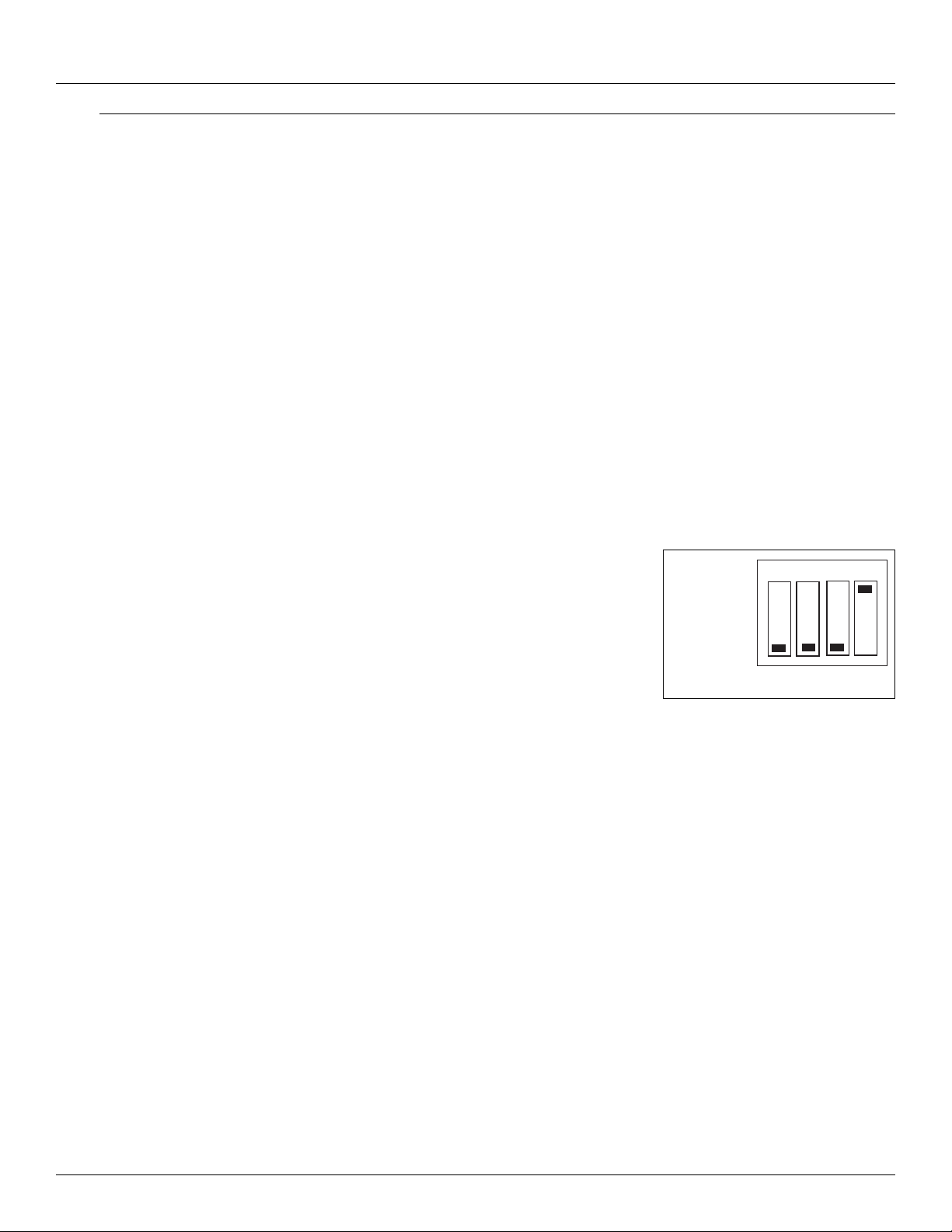
Installation Tank Gate Interface
6.3 Installation
Standard systems are shipped with the motherboard and tank gauge interface module installed.
The Tank Gate Interface installation procedure includes the installation of these individual
components. Tank Gate Interface installation includes the following steps:
1. Mounting the Tank Gate Interface (section 6.3.1 on page 62)
2. Selecting the Unit Address (section 6.3.2 on page 62)
3. Wiring up Power (section 6.3.3 on page 62)
4. Grounding the Tank Gate Interface (section 6.3.4 on page 64)
5. Installing Communications (section 6.3.5 on page 64)
6.3.1 Mounting the Tank Gate Interface
Before mounting the Tank Gate Interface, make certain that any enclosure used can house the
Tank Gate Interface. Refer to the dimensional drawing below (all dimensions are in inches). The
recommended standard housing for the Tank Gate Interface is a NEMA TYPE 4 enclosure. This
enclosure is suitable for both indoor and outdoor applications.
6.3.2 Select the Unit Address
Switch SW1 sets the Tank Gate Interface’s one byte, binary
address (0-15). Switch SW1-1 is the most significant bit
(MSB) while switch SW1-4 is the least significant bit (LSB).
When a switch is in the ON or CLOSED position, the resulting
bit is a one.
Figure 6-1: Switch SW-1 setting for ID 1
CLOSED
OPEN
1234
Address 1 Shown
6.3.3 Wiring Up Power
The Tank Gate Interface operates from AC power.
Wiring 120 or 220 VAC Power
The Tank Gate Interface is powered by an isolation transformer with a 5 volt regulator.
• Remove cover if it is in place
• Connect the two power leads to terminals L and N of connector J2.
• Ensure that a ground connection is connected to the G terminal ground of connector J2. (see
below)
• Install cover.
62 Installation and Operations Manual
Page 73
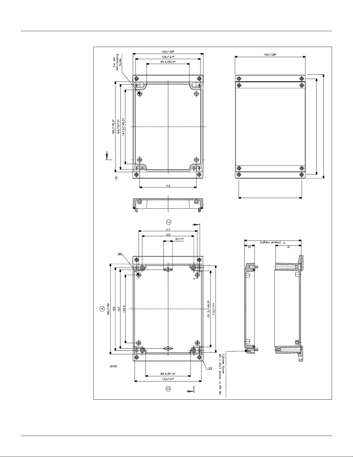
8315 TGI Installation
197
204
125
s
Figure 6-2: Tank Gate Interface Dimensions
Varec, Inc. 63
Page 74

Installation Tank Gate Interface
6.3.4 Grounding
To allow use in harsh industrial environments, the Tank Gate Interface incorporates ANSI/IEEE
surge protection. In solid-state control systems, grounding helps limit the effects of noise due
to electromagnetic interference (EMI) and provides additional surge protection when high
voltage switching circuits are connected to the unit. The grounding path for the Tank Gate
Interface and its enclosure is provided by the equipment grounding connector. The resistance
from the Tank Gate Interface ground to the grounding electrode must not exceed 1 ohm.
Additional ground wires should be connected as required for each I/O module.
Caution! All applicable codes and ordinances must b e ob s erv e d w h en w iri n g t h e Ta n k G a te
Interface.
6.3.5 Installing Communications
6.3.5.1 RS-232 Communications
• To install the RS-232 communication option, connect an RS-232 cable to connector J7
(COM0).
Note The 8311 TGI only supports communication on COM0.
6.3.5.2 Power-Up
Before the field cables are attached, perform an initial system verification.
6.3.5.3 Initial system verification
• Connect the power cable to power connector P1, then connect an RS-232 cable from a PC
with ViewRTU to J7 (COM0).
• Power up the unit.
The CPU LED on the tank gauge interface module should toggle on and off. If the CPU indicator
is not flashing, turn off system power and proceed with the Troubleshooting and Calibration
chapter.
6.3.5.4 Establishing Host Communications
When the main system power is turned on, the Host communications status is set to On-line by
default. The Tank Gate Interface then waits for a valid poll from the Host computer. If the
communication cable is installed and the Host is running, a communications link is established.
Verify this condition with a hand-held terminal or ViewRTU.
6.3.5.5 Verifying Host Communications
• Display the COM Point and verify that an On-line condition is indicated.
64 Installation and Operations Manual
Page 75

8315 TGI Using ViewRTU
7Using ViewRTU
7.1 Overview
This chapter describes the software used to configure the Tank Gate Interface. This chapter
describes each of the menus found in the menu bar. Additionally, the chapter describes the
system requirements and the installation procedure. Use this chapter in accordance with the
Tank Gate Interface Software Blocks section.
ViewRTU software, a Microsoft Windows application, is designed to configure and view data
points in the Tank Gate Interface. ViewRTU is a utility program that can be used for
configuration, diagnostics, data acquisition and control. Since ViewRTU follows the Windows
standard, the user that is familiar with Windows will be able to learn the program quickly.
ViewRTU supports the Windows standard of selecting commands from a series of pull-down
menus. If the user is not familiar with Windows-based programs, then refer to the Microsoft
Windows manual for basic instruction.
7.2 System Requirements
The minimum requirements needed to run the ViewRTU application are listed below:
• 386/486/Pentium Personal Computer
• Microsoft Windows NT, 2000, or XP
• 96 MB RAM
• 2 MB free disk space
• 1 Com Port
7.3 Installing ViewRTU
To install the ViewRTU application, follow the steps listed below.
Installing ViewRTU
• Insert
• Select the drive that contains the disk from the Windows File Manager.
• Double click on the SETUP.EXE file. The setup program prompts the user for the drive and
directory used to install the software.
• Select the drive and type in the directory name. Once the drive and directory are selected,
the setup program copies all of the files to the chosen destination.
• When all of the files have been copied to the destination, the setup program automatically
builds a program group with corresponding program items in the Windows Program
Manager.
the CD into the CDROM or DVDROM drive.
7.4 Executing ViewRTU
This section describes how to start up the ViewRTU program. The components of
the window are also described in this section. To execute the ViewRTU program,
follow the steps below:
Varec, Inc. 65
Page 76

Using ViewRTU Tank Gate Interface
Execute the ViewRTU program,
1. Select the ViewRTU program group from the Windows Program Manager.
2. Double-click on the icon to execute the ViewRTU application.
If more than one Tank Gate Interface definition file (DVR) exists, the following dialog box is
displayed.
Figure 7-1: ViewRTU Version Selection dialog
Each version file contains setup information that matches the firmware in the Tank Gate
Interface. This information allows a single version of ViewRTU to configure multiple versions of
the Tank Gate Interface. For example, MSTG1_00.DVR is a definition file that is compatible with
Tank Gate Interface firmware version 1.00. Select the version that matches the version of
firmware in the Tank Gate Interface. Note that you can determine the firmware version by
viewing the SysVer parameter of the SYS point.
3. Choose the desired version and select OK.
If only one Tank Gate Interface definition file (DVR) exists, the main window appears instead.
The main window is seen below.
When the ViewRTU program is opened, a new file appears in the window. The components of
this window are explained below.
Figure 7-2: Main ViewRTU window with descriptions
66 Installation and Operations Manual
Page 77

8315 TGI Using ViewRTU
7.4.1 ViewRTU window
This main window allows the user to perform the commands necessary to configure the Tank
Gate Interface. The ViewRTU window contains the standard Windows components such as the
Application Control menu, minimize/maximize icon buttons, title bar and menu bar.
The System Status area
Displays the system version as well as general information about the configuration file. The Tank
Gate Interface file name is found in both the System Status area and the title bar.
The Tabular
Contains several push-button icons used to execute frequently used commands found in the
menu bar. In the menu description below, each appears next to its associated menu option.
The Spreadsheet summary
Lists all the point types and corresponding number defined in the file. The Spreadsheet Mode
can be used as a quick method for creating and editing the contents of each point by doubleclicking on the desired point type. The parameters listed in the Spreadsheet summary directly
correlate with each defined point.
Point Icon Selection Area
All the point icons are displayed in the Point Icon Selection Area. Point icons are visual
representations of various software functions. When a new file is opened, several default point
icons are displayed in the Point Icon Selection Area. These points are described in the Tank Gate
Interface Software Blocks chapter.
7.5 The ViewRTU Menu Bar
This section describes all the menus found in the ViewRTU menu bar. The push-button icons
found in the Toolbar are shown next to each associated menu option. This section primarily
describes the functionality of each menu option. ViewRTU applications are presented in the
Application section at the end of the chapter.
7.5.1 The File Menu
The File menu allows the user to create, open, and save configuration files. This menu also
allows the user to save the current configuration to a different file name
Figure 7-3: The File menu
Varec, Inc. 67
Page 78
Using ViewRTU Tank Gate Interface
New
The user is able to create a new configuration file by clicking on the New push-button
from the tool bar or by selecting New from the File menu. When selected, a dialog box
appears displaying a list of configuration definition files. The user selects the desired
file from this list.
Open
The user is able to select an existing configuration file by clicking on the Open pushbutton from the tool bar, or by selecting Open from the File menu. When selected, a
dialog box appears displaying a list of configuration files. All configuration files are
identified by the RCF extension. Once a file is selected, the point configuration data of
the selected file is displayed. If the directory is empty, the user has the option of creating a new
file by typing in the file name.
Save
The user is able to save the opened configuration file by clicking on the Save push-
button from the tool bar or by selecting Save from the File menu. The user can save the
file anytime the configuration has changed. If the file exists in the directory, the
configuration is stored to the disk using the current file name. If the file has not been
saved before or the name does not exist in the directory, the user is prompted to enter a
configuration file name.
Save As
The Save As option is used to save the currently opened file under a different name. When
selected, a dialog box appears prompting the user to enter a file name. If the selected file name
already exists, the user has the option of overwriting the file. Otherwise, the user can create a
separate file containing all the current configuration data of the present file. If the user chooses
to create a separate file, the current file is automatically closed. Only one file may be open at a
time.
Exit
The Exit option is used to close the ViewRTU application. If the current configuration file has not
been saved, the user is prompted to save the file or cancel the option.
7.5.2 The Point Menu
Figure 7-4: The Point Menu
Add
The user is able to add a point to the current configuration. The user is able to add a
point by clicking on the Add Point push-button from the tool bar or by selecting Add
from the Point menu. The Select Point to Add dialog box appears:
68 Installation and Operations Manual
Page 79

8315 TGI Using ViewRTU
Figure 7-5: Dialog viewed when adding a new point
Select Point to Add dialog box
This dialog box displays a list of available point types, the point number, quantity and the
corresponding point icon. The point icon is then added to the Point Icon Selection Area if it does
not already exist. The Point Type lists the currently selected point. The user can select the
desired point by selecting the point from the scroll list.
The Point Number defaults to “0” if the point type has just been defined. The maximum number
of points entered depends on the selected point type. Once entered, the point quantity is
displayed in the Summary Spreadsheet.
Multiple points of the selected type may be created simultaneously by entering the number in
the Quantity edit box.
Edit
This option is used to modify the contents of a selected point. The user is able to edit
an existing point by clicking on the Edit push-button from the toolbar or by selecting
Edit Point from the Point menu. The Select Point to Edit dialog box appears:
Figure 7-6: Edit Point selection dialog
Edit Point selection dialog
This dialog box displays a list of defined point types and corresponding point numbers. The
point icon is also displayed for identification as well as the tag, if a tag has been assigned.
Once a point is selected, the Edit Point dialog box appears:
Varec, Inc. 69
Page 80

Using ViewRTU Tank Gate Interface
Figure 7-7: Edit Point dialog
Edit Point dialog
This dialog box contains all dynamic and configurable field information. The user is able to edit
point data. Exiting this dialog box returns the user to the main window.
Note Several other methods can be used to display the Edit Point dialog box. These methods and other information are explained in greater detail in the Application section.
Delete
This option lets the user delete one point at a time. The user is able to delete an
existing point by clicking on the delete push-button from the toolbar or by selecting
Delete Point from the Point menu. The Select Point to Delete dialog appears:
Figure 7-8: Point deletion dialog
Point deletion dialog
This dialog box displays a list of defined point types and corresponding point numbers. The
point icon is also displayed for identification as well as the tag, if a tag has been assigned.
The user selects the point type and the corresponding number to be deleted.
70 Installation and Operations Manual
Page 81

8315 TGI Using ViewRTU
7.5.3 The Config Menu
Figure 7-9: The Configuration Menu
Download Database to RTU
The Download Database to RTU option is used to download configuration data to the Tank Gate
Interface. The following dialog box appears:
Figure 7-10:Dialog used to download Tank Gate Interface data
Click the Download push-button to download data to the Tank Gate Interface
Upload Database from Tank Gate Interface
The Upload option is used to upload configuration data from the Tank Gate Interface. The
following dialog box appears:
Figure 7-11:Dialog used to upload Tank Gate Interface data
Click the Upload push-button to download data from the Tank Gate Interface. Once the upload
is complete, the main window changes to display the uploaded configuration.
Spreadsheet
The Spreadsheet option is used to configure, download, and upload point data points in
spreadsheet mode.
Varec, Inc. 71
Page 82

Using ViewRTU Tank Gate Interface
Figure 7-12:Spreadsheet Mode Edit window
Password
The user can use the Password option to gain access to a protected file.
Once a password has been assigned, the user must enter the password when attempting to edit
the Tank Gate Interface configuration file. This password is only entered once in the duration of
the ViewRTU program.
To enter the password
• Select Config and click on Password.
• Click on the edit box in the Password dialog. Type in the password.
• Click on OK.
Figure 7-13:Configuration Password dialog
Modify Password
The user can use the Modify Password function to protect all Tank Gauge Configuration files by
issuing and changing a password.
Creating a Password
• Select Config and click on Password. The Change Password dialog appears.
• In the New Password edit box, enter the password. If no password currently exists, leave the
Old Password field blank.
• In the Retype New Password edit box, confirm the entry by reentering the password.
• Click on OK.
Figure 7-14:Change Password dialog
72 Installation and Operations Manual
Page 83

8315 TGI Using ViewRTU
Note Make sure that you write down the password and store it in a secure place.
Changing the Password
• Select Config and click on Modify Change Password. The Change Password dialog appears,
as illustrated in ‘creating a password’.
• In the Old Password edit box, enter the current password.
• In the New Password edit box, enter the new password.
• In the Retype New Password edit box, confirm the entry by reentering the new password.
• Click on OK.
Note Make sure that you write down the password and store it in a secure place.
7.5.4 The Communications Menu
Figure 7-15:The Communications Menu
PC Setup
The PC Setup option allows the user to define the communications channel and data rate
characteristics of the communications port. When selected, the following dialog box appears.
This example dialog box contains the default settings for communications setup.
Figure 7-16:Port Communications Setup dialog
Varec, Inc. 73
Page 84

Using ViewRTU Tank Gate Interface
Port Communications Setup dialog
This dialog box allows the user to enter the specifications of the Tank Gate Interface’s
communication port. When OK is selected, the setup data is stored as the default setup next time
ViewRTU is executed.
Status
The Status option is provided so the user is able to observe communications data. The following
dialog box appears when this option is selected.
Figure 7-17:Communications Diagnostics dialog
Connect
The Connect option is used when the user needs to search for a specific Tank Gate Interface.
The following dialog box appears when the option is selected.
Figure 7-18:Tank Gate Interface search dialog
Tank Gate Interface search dialog
This dialog box lists the address, description and current status of each Tank Gate Interface.
From this dialog box the user can select an Tank Gate Interface and establish communications
with the selected Tank Gate Interface.
74 Installation and Operations Manual
Page 85

8315 TGI Using ViewRTU
7.5.5 The Options Menu
Figure 7-19:The Options Menu
Convert Configuration Files
The Convert Configuration Files option is used once the Download Firmware option has been
executed. This option converts configuration files from one version to another. When selected,
the following dialog box appears.
Figure 7-20:Convert ViewRTU versions dialog
Convert ViewRTU versions dialog
This dialog box allows the user to convert a file. The user has the option of first analyzing the
effects of converting the file. A script file can also be selected to alter the behavior of the
conversion. Script files are provided on the upgrade disk.
Export All
The Export All option allows the user to export all of the database in the Tank Gate Interface.
Each point type is exported to a file in the CSV file format. For example, the Analog Input points
are all exported to the file ‘AI.CSV’. This means that the user can not specify each file name as
the data is exported. The user does have the ability to specify the directory to export the data
to. The user must create and then select the subdirectory for the export operation. We suggest
Varec, Inc. 75
Page 86

Using ViewRTU Tank Gate Interface
that you organize the directories with names corresponding to the Tank Gate Interface address.
If you have two Tank Gate Interface’s, use the Windows File Manager program to create
subdirectories \VIEWRTU\RTU1 and \VIEWRTU\RTU2. All of the files for Tank Gate Interface #1
should be written to \VIEWRTU\RTU1; Tank Gate Interface #2’s data would go to
\VIEWRTU\RTU2 and so on.
The exported data can be edited using a spreadsheet program such as Microsoft Excel, or a
database program like Microsoft Access. Many programs can read and write data in the CSV file
format. You can make backups of your RCF file by exporting the data in the CSV file format.
The exported data can be read back with the Import All option. The Spreadsheet Mode also has
an option to import CSV file data.
Import All
The Import All option allows the user to import the entire Tank Gate Interface database. Each
point type must have been exported previously in order to import data. This can be
accomplished using the Export All option, or by point type using the Spreadsheet Mode. The
data is read from files in the CSV file format. For example, all of the Analog Input points are
imported from the file ‘AI.CSV’. The user must select the subdirectory to import the data from.
The CSV file data can also be imported using the Spreadsheet mode.
View I/O List
The View I/O List option allows the user to create a list of the I/O points connected to the Tank
Gate Interface. The list is limited by listing points that have the Chan or Module parameters.
These parameters are always used in cases where I/O is involved. The list is created by writing
to the file ‘POINTLST.TXT’ and launching the Notepad program. The user can print this file using
Notepad, or exit and return to ViewRTU.
Set Time in RTU
The Set Time in RTU option sets the time in the CLK point to the same time as the PC running
ViewRTU.
7.5.6 The Help Menu
Figure 7-21:The Help Menu
Contents
The Contents option opens the table of contents of the ViewRTU on-line help.
Index
The Index option opens the index for the ViewRTU on-line system. This index lists all the help
screens contained in the help system.
About VRTU
The About RTU... option displays a dialog box describing the copyright information and the
application version number.
76 Installation and Operations Manual
Page 87

8315 TGI Using ViewRTU
7.6 Using ViewRTU
By using ViewRTU, the user is able to define or modify sub-programs called Software Blocks.
Software blocks are used to configure the Tank Gate Interface.
Note Refer to the Tank Gate Interface Software Blocks chapter for specific examples. The
chapter provides a description of the parameters for each point as well as examples of the
connections to other points.
Tank Gate Interface software blocks are functions that the user can configure to perform various
tasks. Software Blocks are available to scan data from a slave device, control a pump, serve data
to other Host systems or perform calculations. Each function type contains both the code and
data necessary to perform the function. Software Blocks are identified by their type (example:
AI, DI, LJ2000 and PUMP). Points are individual instances of software blocks. Each point must be
added and then configured. Adding a point makes the point available for configuration. All
defined points appear in both the Point Icon Selection area and the Spreadsheet Summary in the
main window.
Configuring the point involves entering configuration parameters. In some cases, connections
to other points are required in order to perform a task. Creating connections involves setting
references to allow data to be transferred between points.
7.6.1 Overview
An outline of the section is listed below:
Configuring Single Points
This section describes the method used to configure individual points including:
• Adding a Point
• This section describes how to define a point from the Main window.
• Entering Point Data
• This section describes how to enter the point’s parameters. Parameters are entered from
the Edit Point Window.
• Modifying Strap Tables
• This section describes how to modify strap tables in ViewRTU.
Configuring Multiple Points
This section describes the spreadsheet mode. The principles involved in point configuration are
the same, but the methods are slightly different.
• Adding Multiple Points
• This section describes how to define a point from either the Main window or the
Spreadsheet Mode window.
• Entering Point Data
• This section describes how to enter a point’s parameters. Parameters are entered from the
Spreadsheet Mode window.
Creating and Editing Connections
This section describes how to create connections between various points. Points may be used
to retrieve and/or deliver data from other points.
Varec, Inc. 77
Page 88

Using ViewRTU Tank Gate Interface
7.6.2 Configuring Single Points
Configuring the point involves entering configuration parameters. In some cases, connections
between points must also be required in order to perform a function. All of these steps can be
implemented from the Point Connections window. To display the Point Connections window,
follow one of the methods listed below:
Adding a Point
The user is able to add a point or point type by clicking on the Add Point push-button
from the toolbar or by selecting Add from the Point menu.Once the point is added, the
user is then able to configure the point. Defined point types appear in the Point Icon
Selection Area and in the Spreadsheet Summary of the main window.
Entering Point Data
This section describes how to configure the parameters of any point. Each point has its own Edit
Point window that requires some degree of configuration. Both the configuration and dynamic
attributes of the point are found in the Edit Point Window. From this window, the user is able to
view and edit database parameters.
Several methods can be used to display this window depending on the user’s current location in
the program:
• If in the Main window, select Edit from the Point menu. Select the desired point type and
corresponding point number.
• If in the main window, double-right click on the point icon.
• If in the Point Connections window, double-left click on the focus point icon.
• If in the Point Connections window, double-right click on a point icon other than the focus
point icon.
The following example window appears.
Figure 7-22:Edit (Digital) Point dialog
78 Installation and Operations Manual
Page 89

8315 TGI Using ViewRTU
Edit (Digital) Point dialog
This window is used to view and modify the Dynamic and Configuration parameters of the
selected point. The Edit Point window is identified by the Point Description and associated
current Point Number listed at the top of the window.
This window contains two list boxes and a series of push-buttons. The top list box contains the
configuration parameters of the point, while the bottom list box contains Dynamic and
Command parameters.
The first column contains the name of the parameter and the second column contains
descriptions of the parameters. The third column of the Configuration parameters section
contains the default data. The user can change a value by double-clicking an entry and entering
the new variable. If a Tank Gate Interface is connected and on-line, the third column of the
Dynamic parameters will update in real-time.
Edit Point Window Push-buttons
The user is able to perform a series of functions from selecting the push-buttons found in the
bottom of the Edit Point window. Each push-button is described below.
Minimize
The Minimize push-button creates a “mini window” of selected parameters. This push-button
enables the user to observe relationships between dynamic parameters and how the changes
affect the point.
Clicking the Minimize shrinks the window so that only one or more selected list box parameters
are displayed. The user may have multiple minimize windows opened simultaneously. This
capability is useful for testing and debugging.
Minimizing the Edit Point Window
• Highlight by single-clicking the left mouse button on one or more parameters.
• Click on the Minimize push-button. A following example window appears:
Figure 7-23:Edit Point dialog minimized
Note Parameters can be edited in the minimized mode by double-clicking the right mouse
button on the desired selection.
• To maximize the window, click on the maximize icon or click on the Application
Control menu of the window and select the Maximize menu option.
Connections
The Connections push-button allows the user to switch back to the Point Connections dialog
box.
Next
The Next push-button allows the user to step through the list of points. The us er is able to view
the Edit Point window of the following point number. Selecting Next at the end of the point
number list wraps to the beginning.
Varec, Inc. 79
Page 90

Using ViewRTU Tank Gate Interface
Previous
The Previous push-button allows the user to step through multiple points of a point type. The
user is able to view the data in the Edit Point window of the previous point. Selecting Previous
at the first point number wraps to the last point number of the list.
Examine
The Examine push-button is used to go to the Point Connections window of the reference point
in the list box.
Opening a point connection window
• Highlight the desired reference data parameter from the Edit Point window.
• Click on the Examine push-button.
The user is taken to that reference point’s Point Connections window.
Exit
The Exit push-button exits the current point configuration and returns the user to the main
menu.
Download
The Download push-button allows the user to download the entire point data to the Tank Gate
Interface.
Upload
The Upload push-button allows the user to upload the entire point data from the Tank Gate
Interface.
7.6.3 To modify a Value
Figure 7-24:Edit Point dialog (adding a value)
80 Installation and Operations Manual
Page 91

8315 TGI Using ViewRTU
To modify a value
• Double-click the desired parameter to enter a new value. The following example Modify
Point dialog box appears.
Figure 7-25:Edit point parameter value dialog
Edit point parameter value dialog
From this dialog box, the user is able to enter a value for the selected parameter. The dialog box
varies according to the selected parameter. In some dialog boxes the user is able to enter the
name or data directly in the edit box. Other dialogs contain a scroll list from which the user
selects a value. The new value can then be downloaded to the Tank Gate Interface or stored
locally if the Tank Gate Interface is off-line.
To modify a Reference
There are two ways to modify a reference. One method is performed from the Edit Point window,
and the other method is performed from the Point Connections window. For convenience, both
methods are listed below:
To modify a Reference
• In the Edit Point Window Double-click the desired reference parameter to enter a new value.
The following dialog box appears.
• In the Point Connections Window drag and drop the point icon onto the PntRef. The
following dialog box appears.
Figure 7-26:Edit point parameter reference dialog
Edit point parameter reference dialog
This dialog box is used to select a new point reference, corresponding point reference number,
and/or parameter. If displayed from the Edit Point window, the selection lists the default value.
If displayed from the Point Connections window, the most consistent value is selected as the
default.
Varec, Inc. 81
Page 92

Using ViewRTU Tank Gate Interface
Only valid references appear in the list boxes contained in this dialog box. The new reference
can then be downloaded to the Tank Gate Interface or stored locally if the Tank Gate Interface
is off-line.
7.6.4 Configuring Multiple Points
The spreadsheet mode is one of the methods used to configure points. This method is the most
beneficial when editing and viewing multiple points of the same type. Spreadsheets of each
defined point are found in the Spreadsheet Summary section in the main window.
There are some differences between the regular and spreadsheet methods. First, the user is not
able to view the Point Connections window in Spreadsheet Mode. This mode is used mainly for
viewing and entering point data. Second, the spreadsheet focuses on points of a single type; it
does not offer a “big picture” view of multiple point types.
Adding Multiple Points
The user is able to add a point by using the same method used to add single points.
The user can click on the Add Point icon or push-button from the toolbar or by
selecting Add from the Point menu in the Main window. Once the point is added, the
user is then able to define the point. Defined points appear in the Point Icon Selection
Area and in the Spreadsheet Summary of the Main window.
Note The user can add a point by selecting Add from the Point menu in the Spreadsheet
Mode window. This menu is described later in the section.
Adding Multiple Points
• Double-click on the desired point type in the Spreadsheet Summary. The following example
Spreadsheet Mode window appears.
Figure 7-27:Spreadsheet Mode Window
Note Refer to the following Entering Point Data section for a description of the Spreadsheet Mode window.
Entering Point Data
This section explains the window used to configure multiple points of a single point type. When
the user double-clicks on a point type, the following example dialog box appears:
82 Installation and Operations Manual
Page 93

8315 TGI Using ViewRTU
Figure 7-28:Spreadsheet Mode: Entering point parameter data
Spreadsheet Mode
This window displays a list of all the point numbers of a selected point type. The user is able to
add, configure, and edit points. The user is able to select and enter the parameters for each
point or group of points. The user can also export/import files and control the selection of
displayed parameters.
Compare this window to the Edit Point window (see Figure 7-7 on page 70). The two windows
contain the same parameters. In the spreadsheet mode, the user is able to view and modify all
the points of the selected type. In the Edit Point window, the user steps through a window for
each point number using the Next and Previous push-buttons.
The left two columns, D and U are used to download and upload, respectively, the information
found in the corresponding row(s). The third column lists the point numbers. The Spreadsheet
Mode menu bar contains menus used to perform various functions to one or more points. Each
of the Spreadsheet Mode menus is described below.
The Point Menu
This menu contains the same menu options found in the main window’s menu bar. Refer to The
Point Menu section for a description of the menu options.
Figure 7-29:Spreadsheet Mode: The Point Menu
This option is useful for creating, deleting and editing points without having to exit out of the
Spreadsheet mode.
Varec, Inc. 83
Page 94

Using ViewRTU Tank Gate Interface
The Edit Menu
Figure 7-30:Spreadsheet Mode: The Edit Menu
Copy
The Copy option allows the user to copy data from a one or more selected cells.
1. Select one or more cells to copy. To select one or more rows, click on the number(s). To
select one or more columns, click on the parameter(s).
2. Select the Copy option from the Edit menu. The selected cells outline changes from black
to red.
Note To undo the Copy option, press the Esc key. Pressing the Esc key removes the selection outline from the selected cells.
Paste
The Paste option allows the user to paste the copied group of cells (red outline) to the currently
selected group of cells (black outline).
1. Select the cells on which the copied cells will be pasted.
2. Select the Paste option from the Edit menu.
84 Installation and Operations Manual
Page 95

8315 TGI Using ViewRTU
Figure 7-31:Spreadsheet Mode: Copying and Pasting point parameter data rows.
Note If the number of rows and columns in both selections do not match, the extra copied
cells are truncated. Incompatible cells containing different data types are not copied;
instead a warning is displayed.
Paste & Dnld
The Paste & Dnld option is very similar to the Paste menu selection. The only difference is that
the Paste & Dnld selection downloads the updated data parameters.
Set Value
The Set Value option allows the user to enter or select a value for a parameter.
1. Click on the desired cell or column.
2. Select Set Value from the Edit menu. The Modify Value dialog box appears:
Figure 7-32:Spreadsheet Mode: Editing point parameter values
3. Enter or select a value from the scroll list.
Set Value (with Auto In crement)
This option can also be used for numeric parameters such as channels to auto increment the
value. Follow the procedure below:
Varec, Inc. 85
Page 96

Using ViewRTU Tank Gate Interface
1. Click on each desired cell or column.
2. Select Set Value from the Edit menu. The following dialog box appears:
Figure 7-33:Spreadsheet Mode: Editing point parameter values using auto increment
Each value in the column is incremented by one for the range of rows selected. All cells that are
selected and match the data type of the value are set to the value.
The Options Menu
Figure 7-34:Spreadsheet Mode: The Options Menu
Import
The Import option allows the user to import a point or group of points that match the current
point type. The imported file is named according to the point type with the ‘CSV’ file extension.
Export
The Export option allows the user to export a selected point or all the points that match the
current point type to the default directory. The export file is saved in a file named according to
the point type with the ‘CSV’ file extension
Note The user is able to change the source directory in the INI file.
View
The View option allows the user to display selected parameter types. Selecting this option
displays the following View Point Parameters dialog box.
86 Installation and Operations Manual
Page 97
8315 TGI Using ViewRTU
Figure 7-35:Spreadsheet Mode: Viewing selected parameter types dialog
The user is able to select any combination of parameter types. The user is able to select any
combination of classifications. The classifications are described briefly below.
.
Parameter Type Description
Dynamic Real-time data such as status
Config General specifications such as tag and description
Constant Data that does not change and/or can not be changed
Scratch Temporary data that is typically hidden from the user
Command Output command data
System System data (should not be changed by the user)
Note The default View setting is the Config parameter type.
Hide Row/Col
The Hide Row/Col option allows the user to hide selected rows or columns.
Note The Copy and Paste operations do not affect hidden rows and columns.
1. Select one or more rows or columns.
2. Select the Hide Row/Col option from the Options menu.
The selected rows or columns are indicated by a ‘+’ in the row or column buttons heading. The
following dialog box illustrates this feature.
Varec, Inc. 87
Page 98

Using ViewRTU Tank Gate Interface
Figure 7-36:Spreadsheet Mode: Hiding columns
The user can unhide a row or column by clicking on the associated ‘+’. To unhide all the rows/
columns, the user can select the Unhide All option from the Options menu.
Unhide All
The Unhide All option allows the user to reveal all of the rows or columns that are currently
hidden.
7.6.5 Creating and Editing Connections
Several methods can be used to display this window depending on the user’s current location in
the program. These methods are listed below:
• If in the Main window, double-left click on the point icon.
• If in the Edit Point window, click on the Connections push-button.
• If in the Point Connections window, double-left click on a point icon other than the focus
point to view the Point Connections window for the selected point.
Note If multiple points exist, a selection window is displayed showing all the available
points.
Figure 7-37:Edit Point selection window
88 Installation and Operations Manual
Page 99

8315 TGI Using ViewRTU
Displaying the Point Connections wi ndo w.
• Double-click on one of the icons to display the Point Connections window. The following
example Point Connections window appears.
Figure 7-38:Point Connections Window
Point Connections Window
This graphic display visually illustrates the reference connections of the focus point. From this
display, the user is able to select reference points, create connections between these points, and
enter configuration parameters.
The point icons located in the Icon Bar utilize the drag-and-drop features of Windows. The user
is able to connect the output data of one point to the input of another point.
The connections are made through point references and links. Not all points have references,
but any parameter of a point can be referenced. Some references are incompatible with some
types of data. The program can determine if a reference is valid, but it cannot determine if the
reference is meaningful.
The Input Data parameters, which are located on the left side of the software block, are
references. The Output Data parameters, which are located on the right side, are most
commonly referenced by other points.
To create a Connection:
1. Select the desired point icon from the Icon Bar and drag it onto the desired data parameter.
• If the point dropped does not exist, then the user needs to define the point as
described in the previous section. The same configuration process is used to define the
point.
• If multiple points exist, the user is prompted to select the point number.
• If the point dropped already contains a reference to another input reference, a dialog
box will appear inquiring whether or not to overwrite the existing reference.
2. The point icon will appear to the right or left of the selected arrow as seen Figure 7-38.
Note Double-left clicking on a focus point icon allows the user to view the point’s Edit
Point window.
Varec, Inc. 89
Page 100

Using ViewRTU Tank Gate Interface
Note Double-left clicking on the input source or the output destination icon allows the
user to step through each corresponding Point Connections window, if applicable.
Note Double-right clicking on the input source or the output destination icon allows the
user to view the point’s Edit Point window.
90 Installation and Operations Manual
 Loading...