

Page 1
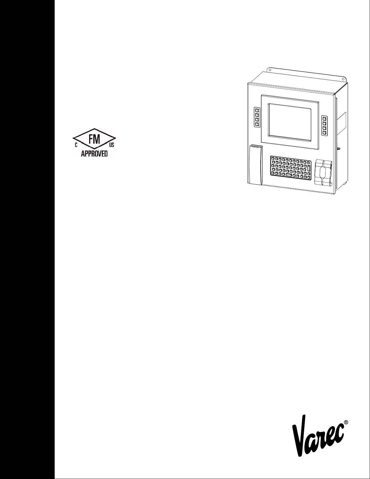
8620 Data Entry Terminal
Field interface used for data entry and
process management at facility control points
Installation and Operations Manual
IOM097GVAE4012
Automation Solutions for oil & gas, defense and aviation applications
Page 2

Page 3

Copyright
All rights reserved. Printed in the United States of America.
Except as permitted under the United States Copyright Act of 1976, no part of this publication
may be reproduced, stored in a retrieval system or transmitted in any form or by any means electronic, mechanical, photocopying, recording, or otherwise - without the prior written
permission of the Publisher:
Varec, Inc.
5834 Peachtree Corners East
Norcross (Atlanta), Georgia 30092
Phone: (770) 447-9202
Fax: (770) 662-8939
Trademarks Acknowledged
Varec, Inc. recognizes all other trademarks. Trademarks of other products mentioned in this
manual are held by the companies producing them.
FuelsManager®, TankView®, TacFuels®, Varec®, and FuelsManager IntoPlane® are
registered trademarks of Varec, Inc.
All other product and service names mentioned are the trademarks of their respective
companies.
Product Approvals
This document and the information provided within are controlled by the approvals agency(s)
listed below. All changes to this document must be submitted to and approved by the agency(s)
before public release.
• FM Approvals (FM)
Varec, Inc. iii
Page 4

Disclaimer of Warranties
The contract between the Seller and the Buyer states the entire obligation of the Seller. The
contents of this instruction manual shall not become part of or modify any prior or existing
agreement, commitment, or relationship between the Seller and Buyer. There are no express or
implied warranties set out in this instruction manual. The only warranties that apply are those
in the existing contract between the Seller and Buyer.
The 8620 Data Entry Terminal (DET) has not been tested by Varec under all possible operational
conditions, and Varec may not have all the data relative to your application. The information in
this instruction manual is not all inclusive and does not and cannot take into account all unique
situations. Consequently, the user should review this product literature in view of his or her
application. If you have any further questions, please contact Varec for assistance.
Limitations of Seller's Liability
In the event that a court holds that this instruction manual created some new warranties, Seller's
liability shall be limited to repair or replacement under the standard warranty clause. In no case
shall the Seller's liability exceed that stated as Limitations of Remedy in the contract between
the Seller and Buyer.
Use of parts that are not manufactured or supplied by Varec voids any warranty and relieves
Varec of any obligation to service the product under warranty. Varec recommends the use of
only Varec manufactured or supplied parts to maintain or service Varec 8620 Data Entry
Terminals.
Terms of Use
The information provided in this document is provided “as is” without warranty of any kind.
Varec, Inc. disclaim all warranties, either express or implied, including the warranties of
merchantability and fitness for a particular purpose. In no event shall Varec, Inc. or its suppliers
be liable for any damages whatsoever including direct, indirect, incidental, consequential, loss
of business profits or special damages, even if Varec, Inc. or its suppliers have been advised of
the possibility of such damages.
This manual is solely intended to describe product installation and functions and should not be
used for any other purpose. It is subject to change without prior notice. This manual was
prepared with the highest degree of care. However, should you find any errors or have any
questions, contact one of our service offices or your local sales agent.
iv Installation and Operations Manual
Page 5

Safety Precaution Definitions
Caution! Damage to equipment may result if this precaution is disregarded.
Warning! Direct injury to personnel or damage to equipment which can cause injury to
personnel may result if this precaution is not followed.
Safety Precautions
Read this manual carefully and make sure you understand its contents before using this product.
Follow all instructions and safety guidelines presented in this manual when using this product.
If the user does not follow these instructions properly, Varec cannot guarantee the safety of the
system.
Note Comply with all applicable regulations, codes, and standards. For safety precautions,
the user should refer to the appropriate industry or military standards.
Caution! Electrical Hazard! Read and understand static and lightning electrical protection
and grounding described in API 2003. Make certain that the 8620 Driver Entry Terminal
(DET) installation, operation, and maintenance conforms with the practice set forth therein.
Make sure the power is turned off at the main circuit breaker or switch. The power switch
should be in the OFF position, locked, and labeled to prevent other personnel from turning
the power on during installation.
Varec, Inc. v
Page 6

vi Installation and Operations Manual
Page 7

Contents
1 Introduction. . . . . . . . . . . . . . . . . . . . . . . . . . . . . . . . . . . . . . . . . . . . . . . . . . . . . 1
1.1 Overview. . . . . . . . . . . . . . . . . . . . . . . . . . . . . . . . . . . . . . . . . . . . . . . . . . . . . . . 1
1.2 Functionality and System Design . . . . . . . . . . . . . . . . . . . . . . . . . . . . . . . . . . . . 3
2 Preparing for Installation. . . . . . . . . . . . . . . . . . . . . . . . . . . . . . . . . . . . . . . . 5
2.1 Site Preparation Checklist. . . . . . . . . . . . . . . . . . . . . . . . . . . . . . . . . . . . . . . . . . 5
2.2 General Safety Guidelines . . . . . . . . . . . . . . . . . . . . . . . . . . . . . . . . . . . . . . . . . 5
2.3 Installation Safety Guidelines . . . . . . . . . . . . . . . . . . . . . . . . . . . . . . . . . . . . . . . 5
2.4 Unpacking. . . . . . . . . . . . . . . . . . . . . . . . . . . . . . . . . . . . . . . . . . . . . . . . . . . . . . 6
2.5 Installation. . . . . . . . . . . . . . . . . . . . . . . . . . . . . . . . . . . . . . . . . . . . . . . . . . . . . . 6
3 Wiring. . . . . . . . . . . . . . . . . . . . . . . . . . . . . . . . . . . . . . . . . . . . . . . . . . . . . . . . . . . 9
3.1 Overview. . . . . . . . . . . . . . . . . . . . . . . . . . . . . . . . . . . . . . . . . . . . . . . . . . . . . . . 9
3.1.1 Power. . . . . . . . . . . . . . . . . . . . . . . . . . . . . . . . . . . . . . . . . . . . . . . . . . . 12
3.1.2 Communications . . . . . . . . . . . . . . . . . . . . . . . . . . . . . . . . . . . . . . . . . . . 12
3.2 Communications Wiring . . . . . . . . . . . . . . . . . . . . . . . . . . . . . . . . . . . . . . . . . . 13
4 Configuration . . . . . . . . . . . . . . . . . . . . . . . . . . . . . . . . . . . . . . . . . . . . . . . . . . 15
4.1 Configuring the DET.Config File . . . . . . . . . . . . . . . . . . . . . . . . . . . . . . . . . . . . 16
5 Maintenance and Troubleshooting . . . . . . . . . . . . . . . . . . . . . . . . . . . . . 19
5.1 Maintenance . . . . . . . . . . . . . . . . . . . . . . . . . . . . . . . . . . . . . . . . . . . . . . . . . . . 19
5.2 Troubleshooting . . . . . . . . . . . . . . . . . . . . . . . . . . . . . . . . . . . . . . . . . . . . . . . . 21
5.2.1 Using Local Diagnostics (LED Indicators). . . . . . . . . . . . . . . . . . . . . . . . . . 21
5.2.2 Replacing the main circuit fuse . . . . . . . . . . . . . . . . . . . . . . . . . . . . . . . . . 22
5.2.3 Replacing the I/O Module fuse on the OPTO 22 board. . . . . . . . . . . . . . . . . 22
5.2.4 Replacing the Battery. . . . . . . . . . . . . . . . . . . . . . . . . . . . . . . . . . . . . . . . 23
5.2.5 8620 DET Voltage Monitor . . . . . . . . . . . . . . . . . . . . . . . . . . . . . . . . . . . . 24
5.2.6 Resetting the 8620 DET . . . . . . . . . . . . . . . . . . . . . . . . . . . . . . . . . . . . . . 24
6 Specifications. . . . . . . . . . . . . . . . . . . . . . . . . . . . . . . . . . . . . . . . . . . . . . . . . . 25
6.1 General . . . . . . . . . . . . . . . . . . . . . . . . . . . . . . . . . . . . . . . . . . . . . . . . . . . . . . . 25
6.2 System Components. . . . . . . . . . . . . . . . . . . . . . . . . . . . . . . . . . . . . . . . . . . . . 25
6.3 Host Communication. . . . . . . . . . . . . . . . . . . . . . . . . . . . . . . . . . . . . . . . . . . . . 27
6.4 Environmental. . . . . . . . . . . . . . . . . . . . . . . . . . . . . . . . . . . . . . . . . . . . . . . . . . 27
6.5 Electrical . . . . . . . . . . . . . . . . . . . . . . . . . . . . . . . . . . . . . . . . . . . . . . . . . . . . . . 27
6.6 Mechanical Construction. . . . . . . . . . . . . . . . . . . . . . . . . . . . . . . . . . . . . . . . . . 27
6.7 Certifications and Approvals . . . . . . . . . . . . . . . . . . . . . . . . . . . . . . . . . . . . . . . 27
7 Ordering Information. . . . . . . . . . . . . . . . . . . . . . . . . . . . . . . . . . . . . . . . . . . 29
7.1 Order Codes . . . . . . . . . . . . . . . . . . . . . . . . . . . . . . . . . . . . . . . . . . . . . . . . . . . 29
Varec, Inc. vii
Page 8

Contents
viii Installation and Operations Manual
Page 9

1 Introduction
1.1 Overview
8620 Driver Entry Terminal
This manual provides the information needed to install, maintain, and troubleshoot the Varec
8620 Driver Entry Terminal (DET).
The 8620 DET is a field interface device designed for data entry and process management at
facility control points, such as entry and exit gates, load racks, BOL request stations, weight
scale stations, and preload stations. It features multiple interface components, such as a display,
card reader, and fingerprint scanner that can be used to enter and record pertinent information
about the operator or operation.
The 8620 DET interfaces to FuelsManager® Oil and Gas Terminal Automation Edition software.
It captures data based on the desired configuration for the specific control point application,
process, or operation. For example, it may capture driver ID for access control, truck ID for
equipment safety, and loading or company ID for product allocations. Refer to the
Software User Guide(s)
and documentation for your specific implementation.
FuelsManager
Varec, Inc. 1
Page 10
Introduction
1
2
4
7
8
5
3
6
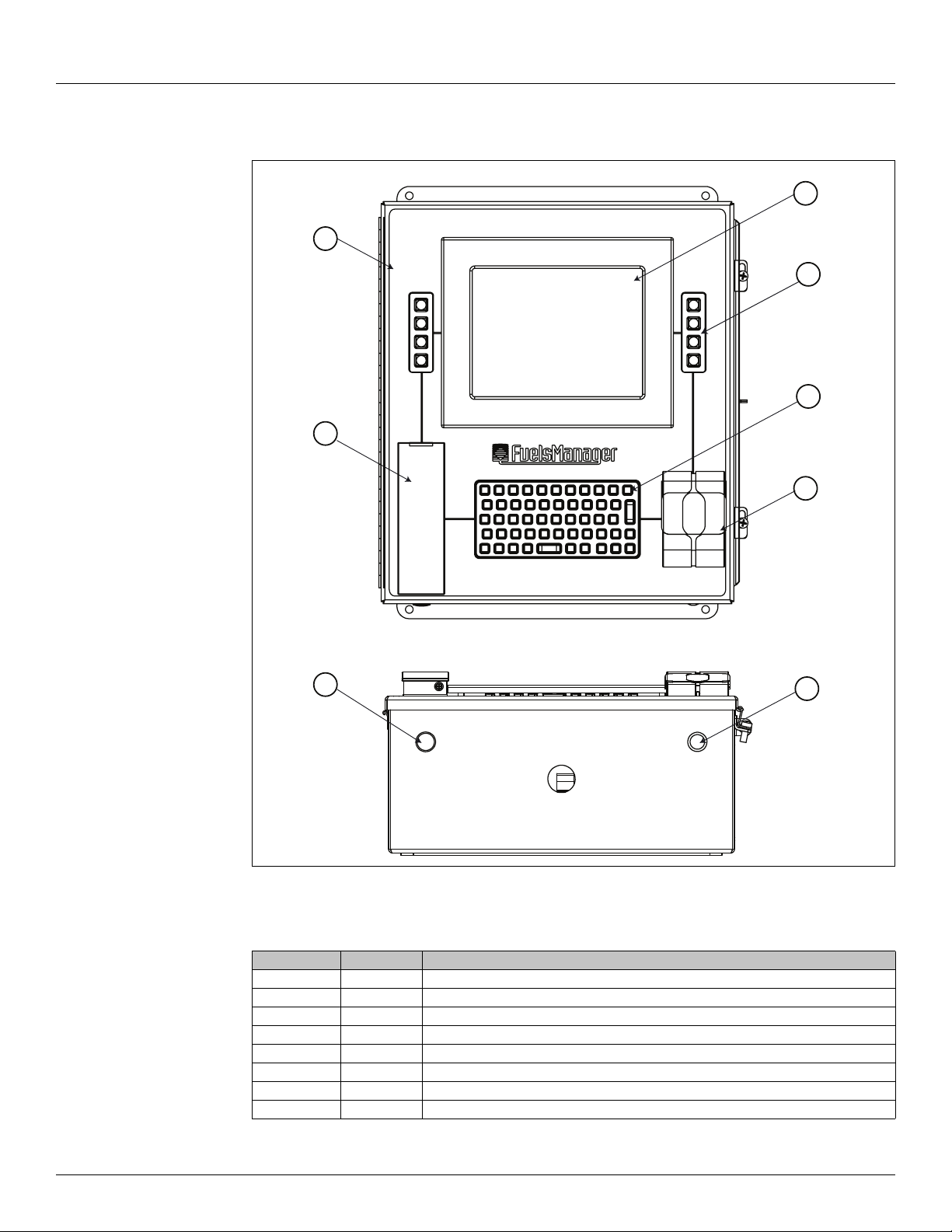
The 8620 DET is constructed with the following assemblies as shown in Figure 1-1:
Figure 1-1: 8620 DET System Components
Item Qty Description
1 1 17.50" x 14.92" Enclosure with Window Kit
2 1 8.4" LCD
3 1 Fingerprint Scanner
4 2 4-Key Keypad
5 1 Smart Card Reader
61Keyboard
71LED Indicator
8 1 Reset Button
Table 1-1: 8620 DET System Components
2 Installation and Operations Manual
Page 11
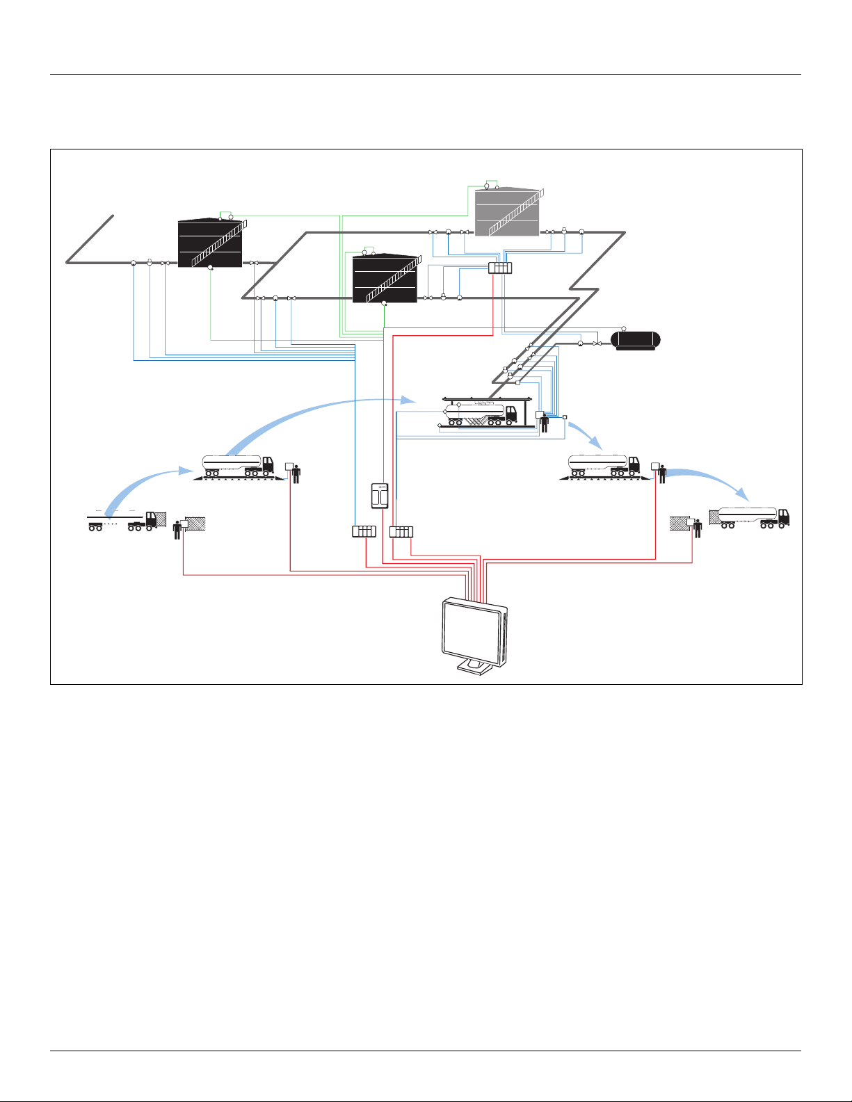
1.2 Functionality and System Design
Load Rack
• Preset Blending Control
• Preset Additive Injection Control
Entry Gate
• Access Control
• Truck Identity
• Truck Status
Weigh Scale
• Select Order to Load
• Configure Compartment Loads
• Capture Empty Weight
Exit Gate
• Exit Control
• Truck Identity
• Truck Status
Tank Storage
• Tank Gauging
• Inventory Management
• Alarms & Events
• Tank Trends
• Leak Detection
• Certificate of Analysis Records
Additives
• Tank Gauging
• Inventory Management
Pipeline, Truck, Rail or
Barge Receipts
Pump Meter Valve
Pump Valve
MeterValve Pump
Driver
Entry
Terminal
Driver
Entry
Terminal
Preset
Meter
Valve
Pump
Pump Valve
Valve
Tank Gauges
Tank Gauges
Leak
Detection
System
Injector
Tank Gauges
Valve
Valve
Overfill
Protection
Ground
Protection
Tank Gauges
Valve
Pump
PLC
RTU
Leak
Detection
System
MeterValve Pump
ESD
Driver
Entry
Terminal
Vapor
Recovery
PLC
PLC
SCADA
• Pump & Valve Control
• Emergency Shut Down
Weigh Scale & BOL Station
• Captured Load Weight
• Automatic BOL Printing
• Automatic COA Printing
• Truck Status
Driver Entry
Terminal & Printer
FuelsManager
System
8620 DET
8620 DET
8630 DET
8630 DET
8620 Driver Entry Terminal
Figure 1-2: 8620 DET System Diagram
Varec, Inc. 3
Page 12

Introduction
4 Installation and Operations Manual
Page 13

2 Preparing for Installation
This chapter provides a site preparation checklist, safety information, unpacking instructions,
and installation instructions.
2.1 Site Preparation Checklist
Before installing the 8620 DET, ensure the following items:
• The use of a protective canopy or sunshade is recommended in order to shield the
driver entry terminal from direct sun, rain, and snow
• Adequate space for installation
• The appropriate communication lines back to the FuelsManager Oil & Gas Terminal
Automation system
• Power (AC or DC)
• Grounding
• Enclosure protection, such as concrete barrier poles to prevent trucks from damaging
the unit
8620 Driver Entry Terminal
2.2 General Safety Guidelines
The user shall follow safety guidelines provided by the Occupational Safety and Health
Administration (OSHA) for additional protection. Information may also be obtained from the
following sources:
• National Electrical Code (NEC)
• National Fire Protection Association (NFPA)
• Instrument Society of America (ISA)
• FM Approvals (FM)
• Underwriters Laboratories Incorporated (UL)
When in doubt about the safety of an area, check with the local safety authorities. Always
observe equipment labels and warning signs posted in the area.
2.3 Installation Safety Guidelines
This equipment should be installed only by qualified personnel familiar with the installation of
display and monitoring equipment.
Caution should be exercised when any area that is posted or otherwise assumed to contain
hazardous gases. Always follow OSHA guidelines.
To prevent shock hazards, the housing of all units should be properly grounded in accordance
with the National Electrical Code. A grounding conductor should be wired to the grounding
terminal provided on the 8620 DET.
! Warning Before attempting installation of the 8620 DET, review the “General Safety
Guidelines” section above. Installation and maintenance personnel should
become familiar with any hazards present as well as any agency requirements
before working with any equipment.
Obtain a hot work permit before performing maintenance on the 8620 DET with power applied.
Varec, Inc. 5
Page 14

Preparing for Installation
2.4 Unpacking
Before installing/repairing any wiring to the 8620 DET, make sure that the power is turned off
at the main circuit breaker or switch. The power switch should be locked in the OFF position and
labeled to prevent other personnel from turning the power on during installation.
Do not apply power until the 8620 DET is properly grounded.
Do not apply power unless the environment is known to be non-hazardous.
Incorrect field wiring connections can damage the 8620 DET electronics and cause system
malfunctions.
Varec’s 8620 DET(s) are shipped fully assembled and ready for installation.
To unpack the 8620 DET, follow the steps below:
1. Place the shipping container on a secure bench.
2. Open the shipping container, taking care not to damage the contents.
3. Carefully remove the 8620 DET from the shipping container and place it on the bench.
4. Inspect the 8620 DET for shipping damage. Report any damage to the carrier and Varec.
2.5 Installation
Note If the 8620 DET must be stored prior to installation, it should be repacked in its ship-
ping container and stored in a temperature-and-humidity-controlled environment.
To install the 8620 DET, follow the steps below:
1. Verify proper 8620 DET configuration for the RS-232, RS-422/485, or Ethernet protocol.
2. Ensure proper grounding of the 8620 DET.
3. Ensure proper mounting of the 8630 DET. Refer to Figure 2-1 on page 7 for dimensions
and mounting holes.
4. Based on the application (trucks, cars, and pedestrians), ensure that the 8620 DET can be
mounted at a suitable height.
5. Install proper mounting hardware (pole, stand, or wall).
6. Install the 8620 DET to the mounting hardware. The mounting hardware must be capable
of supporting the 8620 DET. If mounted to a wall with stud framing, make sure the fasteners are securely mounted into the studs.
7. Run the conduit and wiring to the 8620 DET. To maintain the Ingress Protection rating of
the 8620 DET, waterproof conduit connections must be used.
8. Power up and verify communications.
Note Quality electrical wiring is necessary for proper operation. Poor quality electrical wiring may cause a drop in the supply voltage. For DC-powered units, verify that the voltage
at the DET during startup and operation is within the recommended operating voltage range
of 24 to 48 VDC.
6 Installation and Operations Manual
Page 15
6.44
5.70
8620 Driver Entry Terminal
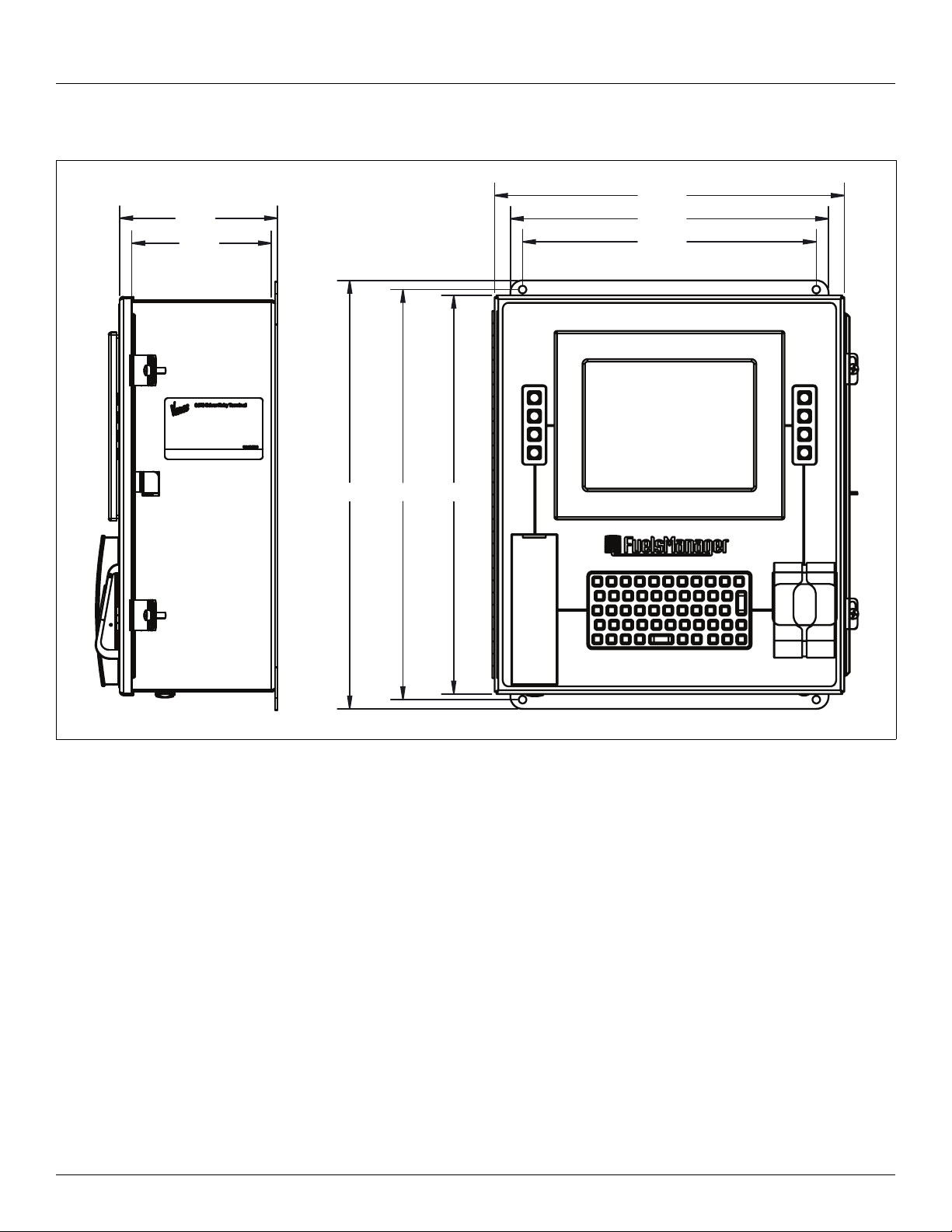
Figure 2-1 shows the dimensions of the 8620 DET.
14.28
13.00
12.00
16.75 17.50
Figure 2-1: 8620 DET Dimensions
16.28
Varec, Inc. 7
Page 16

Preparing for Installation
8 Installation and Operations Manual
Page 17

3 Wiring
3.1 Overview
8620 Driver Entry Terminal
This chapter describes wiring requirements for the 8620 DET. Wiring should be performed after
the unit is installed.
Field wiring of the 8620 DET consists of the following:
• Power (AC/DC)
• Communications (RS-232, RS-485/422, or Ethernet)
• Digital I/O (Optional)
• Power Disconnect Device
a. a switch or circuit-breaker shall be included in the building installation;
b. it shall be in close proximity to the equipment and within easy reach of the operator;
and
c. it shall be marked as the disconnecting device for the equipment.
Varec, Inc. 9
Page 18
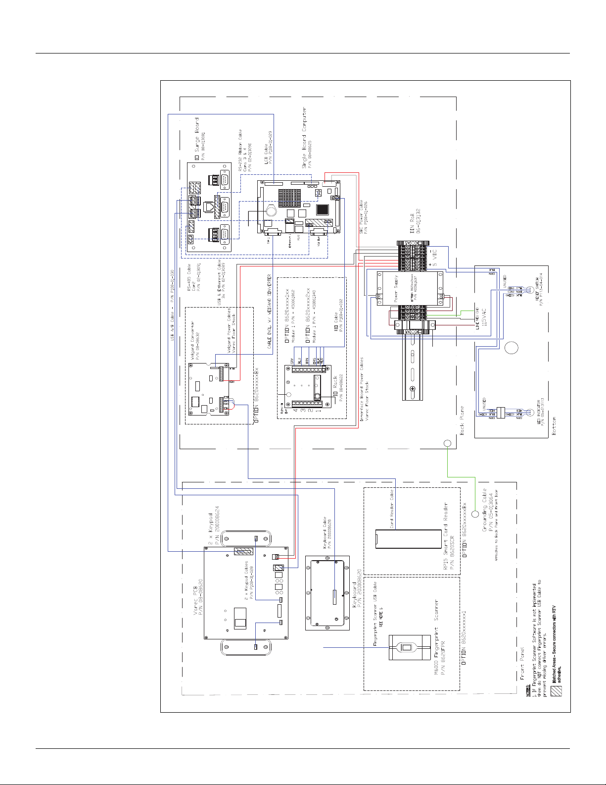
Wiring
CPU Board
Battery
Note: DIN Rail Wiring:
AC: P108-14-001: 14 AWG, 300 V MIN., 105 °C, UL/CSA-BLACK
P108-14-001: 14 AWG, 300 V MIN., 105 °C, UL/CSA-WHITE
DC: P108-50-001: 18 AWG, 300 V MIN., 105 °C, UL/CSA-BLACK
P108-50-003: 18 AWG, 300 V MIN., 105 °C, UL/CSA-RED
Fuse
Holder
Spare
Fuse
Fuse
BLK
RED
Figure 3-1: 8620 DET AC Wiring Diagram
10 Installation and Operations Manual
Page 19
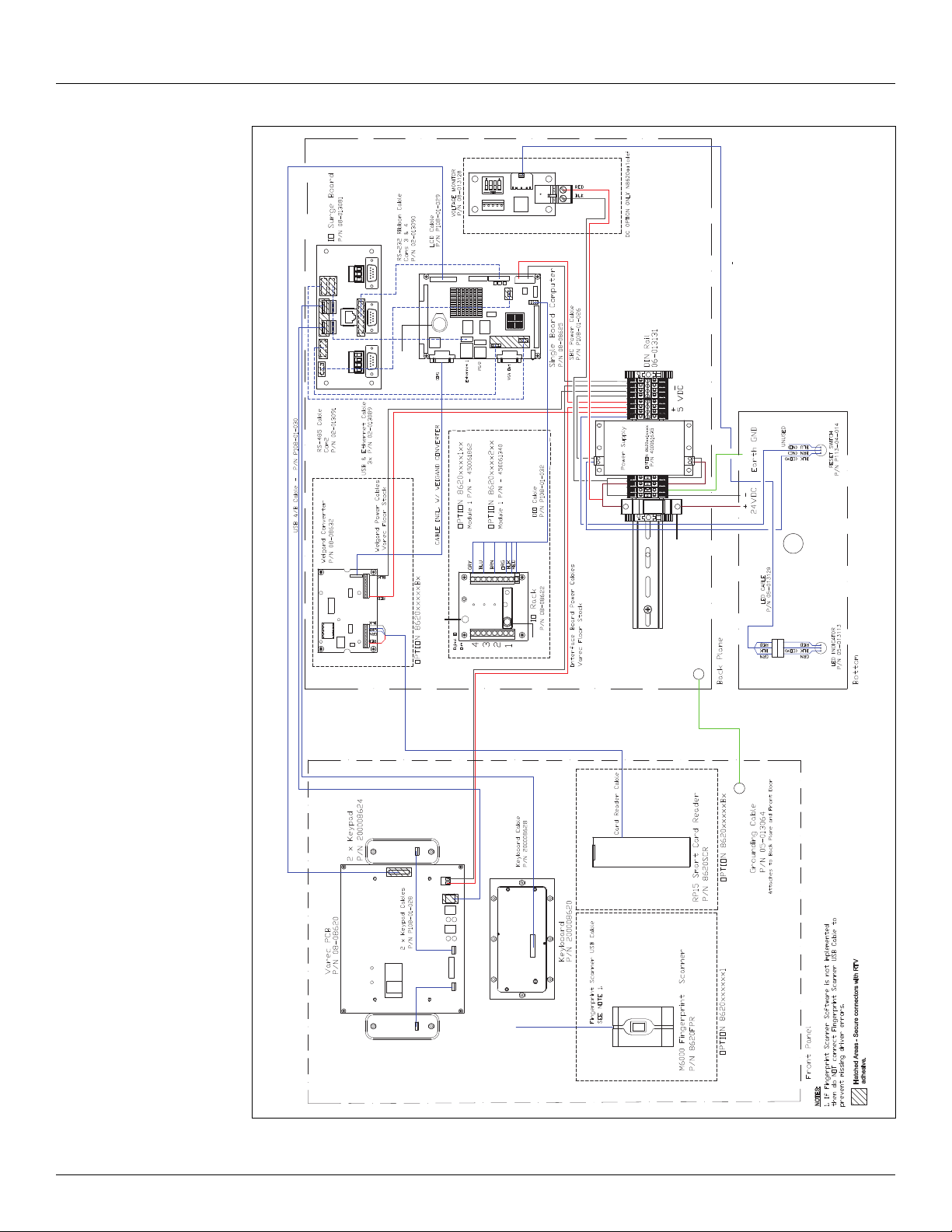
8620 Driver Entry Terminal
Blk
Red
Fuse
Spare
Fuse
CPU Board
Battery
Fuse
Holder
Blk
Red
Note: DIN Rail Wiring:
DC: P108-50-001: 18 AWG, 300 V MIN., 105 °C, UL/CSA-BLACK
P108-50-003: 18 AWG, 300 V MIN., 105 °C, UL/CSA-RED
Figure 3-2: 8620 DET DC Wiring Diagram
Varec, Inc. 11
Page 20
Wiring
3.1.1 Power
To connect DC or AC power to the 8620, connect the power wires to the appropriate terminals
supplied with the 8620 DET.
Note Before connecting power wires to the 8620 DET, ensure that the power is switched
off and that the 8620 DET is correctly grounded.
AC Wiring
To connect the AC wiring, perform the following steps:
1. Connect the hot wire to the fuse holder as shown in Figure 3-1 on page 10.
2. Connect the neutral wire to the black terminal as shown in Figure 3-1 on page 10.
3. Connect the ground wire to the green/yellow terminal.
DC Wiring
To connect the DC wiring, perform the following steps:
1. Connect the 20 - 48 VDC positive wire to the bottom of the fuse holder as shown in
Figure 3-2 on page 11.
2. Connect the negative wire to black terminal as shown in Figure 3-2 on page 11.
3. Connect the ground wire to the green/yellow terminal.
3.1.2 Communications
RS-485 is the default setting used for Com 2 as shown in Figure 3-1 on page 10.
RS-422 and RS-485 Wiring — Com 2
Pin Pin Name Signal Type
1 422-RXD- IN
2 422-RXD+ IN
3 485-422-TXD+ OUT
4 485-422-TXD- OUT
Table 3-1: 4-Pin Connectors for RS-422 and RS-485 Communication Protocols
Note Com 1, Com 3, and Com 4 are all standard RS-232 Ports. All communications ports
are standard DB-9 male connectors. Com 2 also supports RS-232 if properly configured.
DB-9 Connector on I/O Bracket
12 Installation and Operations Manual
Page 21
8620 Driver Entry Terminal
Digital I/O Wiring
Four digital I/O modules can be installed in the 8620 DET. Field wiring should be installed
directly onto the Digital I/O Rack as shown in Table 3-2 and Table 3-3.
Pin Pin Name
2I/O 1+
3I/O 1-
4I/O 2+
5I/O 2-
6I/O 3+
7I/O 3-
8I/O 4+
9I/O 4-
Table 3-2: Field Terminal
Pin Wire Color Terminal
1 Red Standard Voltage
2 Black GND
3Orange I/O 1
4Empty N/A
5 Brown I/O 2
6Empty N/A
7Blue I/O 3
8Empty N/A
9Gray I/O 4
Table 3-3: Control Terminal — to Single Board Computer
Ethernet Wiring
The 8620 DET has two 100-Base-T Ethernet jacks. One is located on the side of the single board
computer. The second one is located on the communications terminal as shown in Figure 3-1
on page 10. Standard 8-pin RJ-45 connectors are used for ethernet wiring.
3.2 Communications Wiring
Table 3-4 describes the wiring considerations for each communications protocol.
Communication Protocol Description
Ethernet Maximum length of 250 feet of twisted pair CAT5 cable.
RS-232 Maximum length of 50 feet of cable.
RS-485/422 Maximum length of 4000 feet of cable.
Table 3-4: Communications Wiring Information
Varec, Inc. 13
Page 22

Wiring
14 Installation and Operations Manual
Page 23
4 Configuration
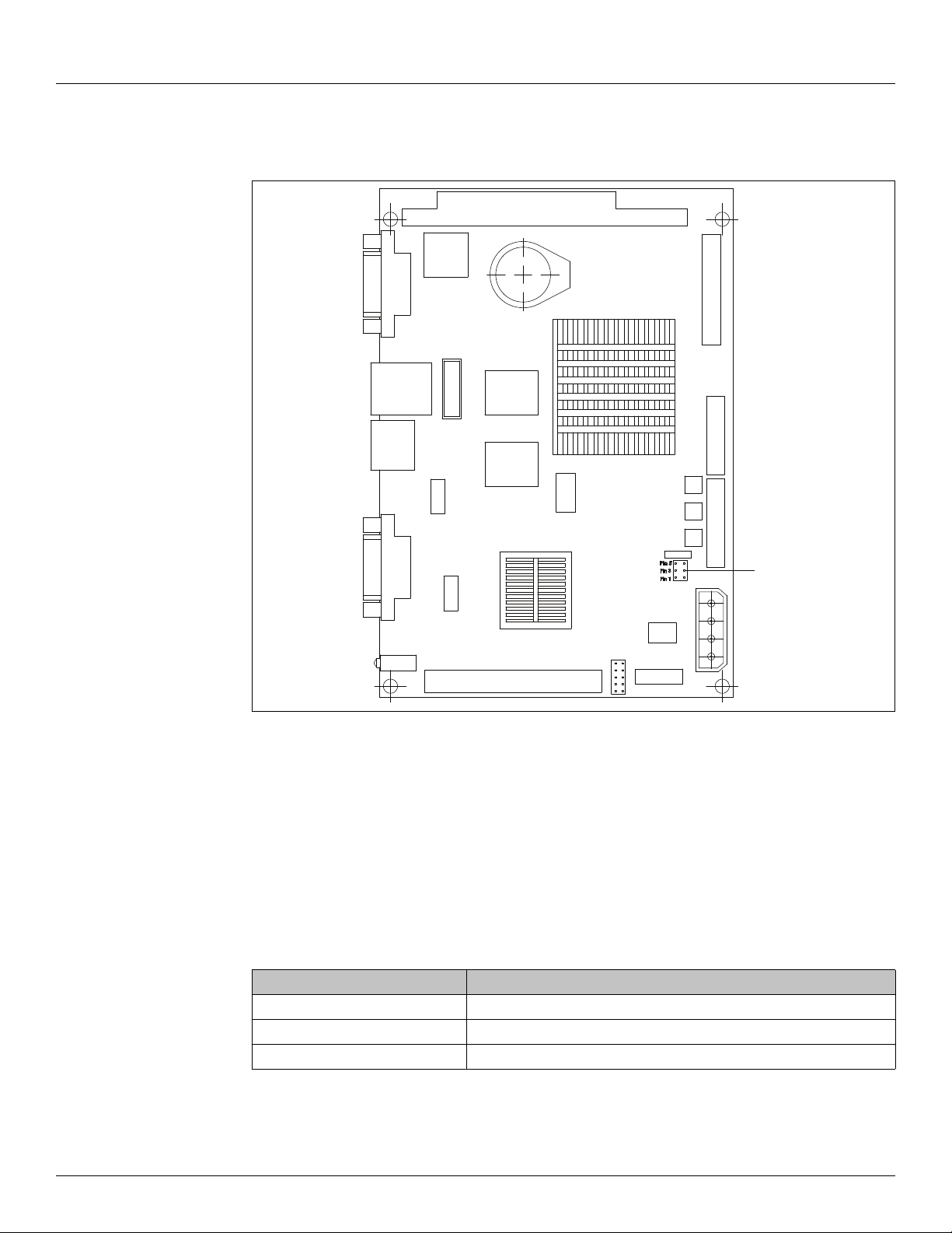
J3
8620 Driver Entry Terminal
Figure 4-1: J3 on the Single Board Computer
Configuring the 8620 DET consists of the following:
• Configuring the RS-232 Com port (Com 1, 2, 3, and 4)
• Configuring the RS-485/422 or RS-232 Com port (Com 2)
• Configuring the DET.Config File
Note Com 2 is a dual protocol port that can be an RS-232 or an RS-485/422 communi-
cations protocol set by jumper J3 on the single board computer (see Figure 4-1
above) as shown in Table 4-1.
Setting Function
1-2 RS-232
3-4 RS-485 (Default)
5-6 RS-422
Table 4-1: Com 2 Setting (J3)
Varec, Inc. 15
Page 24

Configuration
4.1 Configuring the DET.Config File
The DET.Config file is found on the “Local Drive” directory in the Single Board Computer. The
values are edited to configure the DET.
Note Be aware that making direct edits to the DET.Config file can result in improper
system behavior if not done in accordance with proper XML syntax.
In NotePad, modify the DET.Config file by replacing the necessary variables as shown in the
following example (see Table 4-2 below for more information about the variables used in the
config file):
Example:
<configuration Title=”VarecDET” HostInterfaceType=”Network”
TouchScreen=”False” Watchdog=”False”>
<HostSerialInterface Name=”COM2:” BaudRate=”9600” Parity=”none” DataBits=”8”
StopBits=”one” Address=”1” />
<HostNetworkInterface Port=”4096” />
16 Installation and Operations Manual
Page 25
8620 Driver Entry Terminal
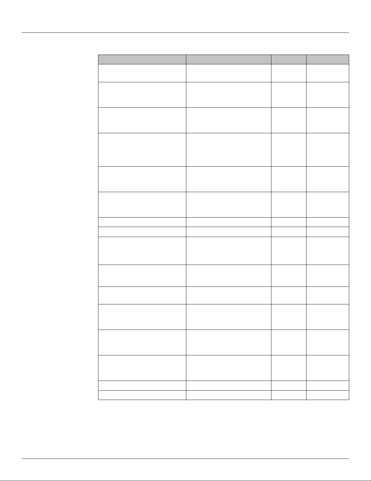
Variables Description Values Value Notes
HostInterfaceType Sets the Host Interface to either
Serial or Network
TouchScreen Configures DET Software for
Touchscreen Interface (Currently
Touchscreen Not Supported)
Network
Serial Default
TRUE
FALSE Default
Watchdog Enables Watchdog Feature
(Currently Not Supported DO NOT
Enable)
HostInterface Name If HostInterfaceType is set to
Serial, this parameter sets the
ComPort.
BaudRate Sets the Serial Baud Rate 4800
Parity Sets the Serial Parity None
DataBits Sets the Serial Data Bits 8 Default
StopBits Sets the Serial Stop Bits one Default
Address Sets the Serial Address. If using
more than one DET on an RS-485
loop, then each must have a
unique address.
HostNetworkInterface Port If HostinterfaceType is set to
Network, this parameter sets the
Network Port.
CardReaderSerial InterfaceEnabled This parameter enables or
disables the Card Reader.
Name If CardReadSerialInterface is
Enabled, this parameter sets the
ComPort.
BaudRate Sets the Card Reader Baud Rate 4800
Parity Sets the Card Reader Parity None
DataBits Sets the Card Reader Data Bits 8 Default
StopBits Sets the Card Reader Stop Bits 1 Default
TRUE
FALSE Default
Com 1
Com 2
Com 3
Com 4
9600
19200
Even
Odd
1
4096
TRUE
FALSE
Com 1
Com 3
Com 4
9600
19200
Odd
Even
RS232
RS485/RS232
RS232
RS232
Default
Default
Default
Default
Table 4-2: Variables Used in the DET.Config File
Varec, Inc. 17
Page 26

Configuration
18 Installation and Operations Manual
Page 27
5 Maintenance and Troubleshooting
1
18
2
3
6
5
7
11
17
16
13
19
12
14
8
9
20
15
4
10
4
5.1 Maintenance
Maintenance should be performed only by authorized personnel.
8620 Driver Entry Terminal
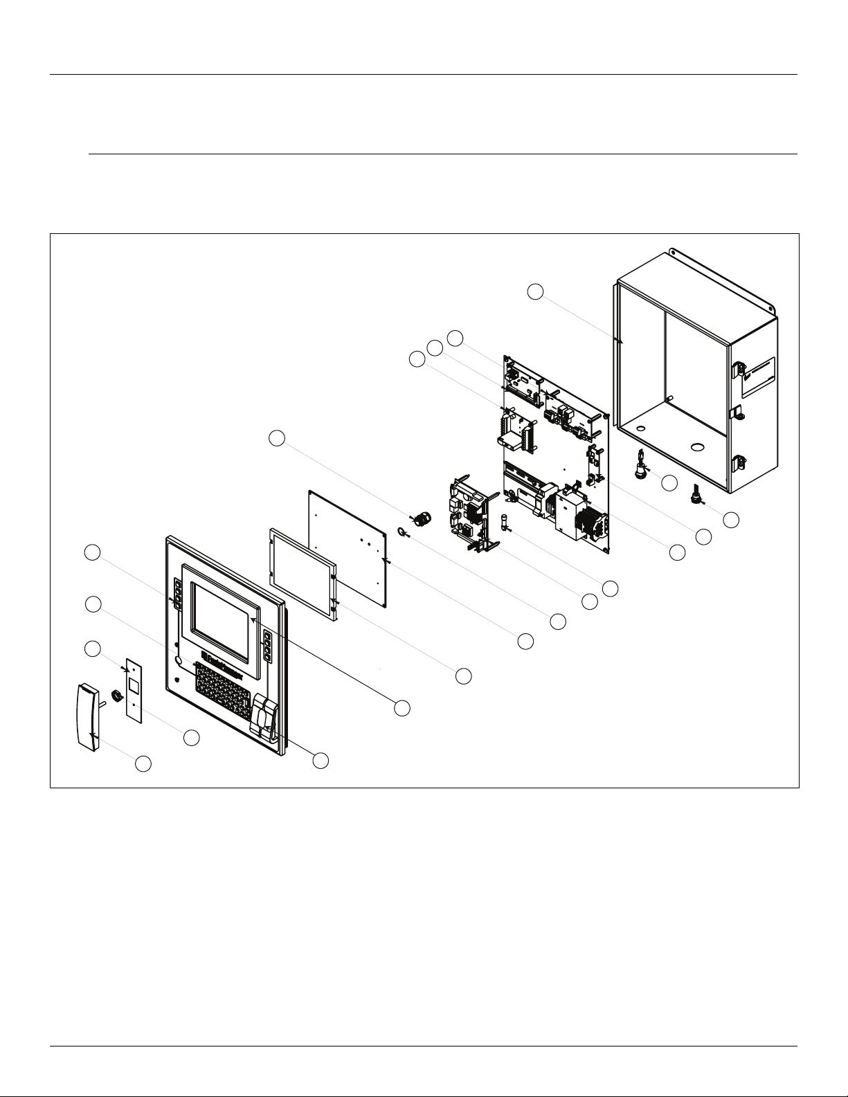
Figure 5-1: 8620 DET Assembly Diagram
Varec, Inc. 19
Page 28
Maintenance and Troubleshooting
Item Part No. Quantity Description
1 8620SCR 1 Smart Carder Reader
2 P14-08620 1 Card Reader Gasket
3 8620FPR 1 Biometric Fingerprint Scanner w/Gasket
4 14001586 1 DET Enclosure including Window Kit
5 200008624 2 4-Key Keypads w/Gasket
6 200008620 1 Alphanumeric Keyboard
7 280061862 1 8.4" TFT (640 x 480, 64,000 Colors) VGA LCD Display
8 08-08622 1 I/O Rack w/Cable
9 08-08632 1 RS-232/Weigand Converter
10 08-01381 1 I/O Surge Board
11 08-012944 1 8620 Interface Board
12 40061635 1 DC Power Supply
13 08-08625 1 32-Bit Single Board Computer
14 08-08625 1 Voltage Monitor PCB Assembly
15 08-08625 1 Push Button Switch (Reset Button)
16 P102-22-025 1 Wire Grommet
17 P102-22-027 1 Wire Grommet O-Ring
18 P102-22-026 1 Wire Grommet Lock Nut
19 P116-01-044 1 Fuse - Class I, Division 2
20 05-013113 1 LED Green/Red Indicator Light Assembly
40061637 1 AC Power Supply
Table 5-1: 8620 DET Spare Parts List
20 Installation and Operations Manual
Page 29
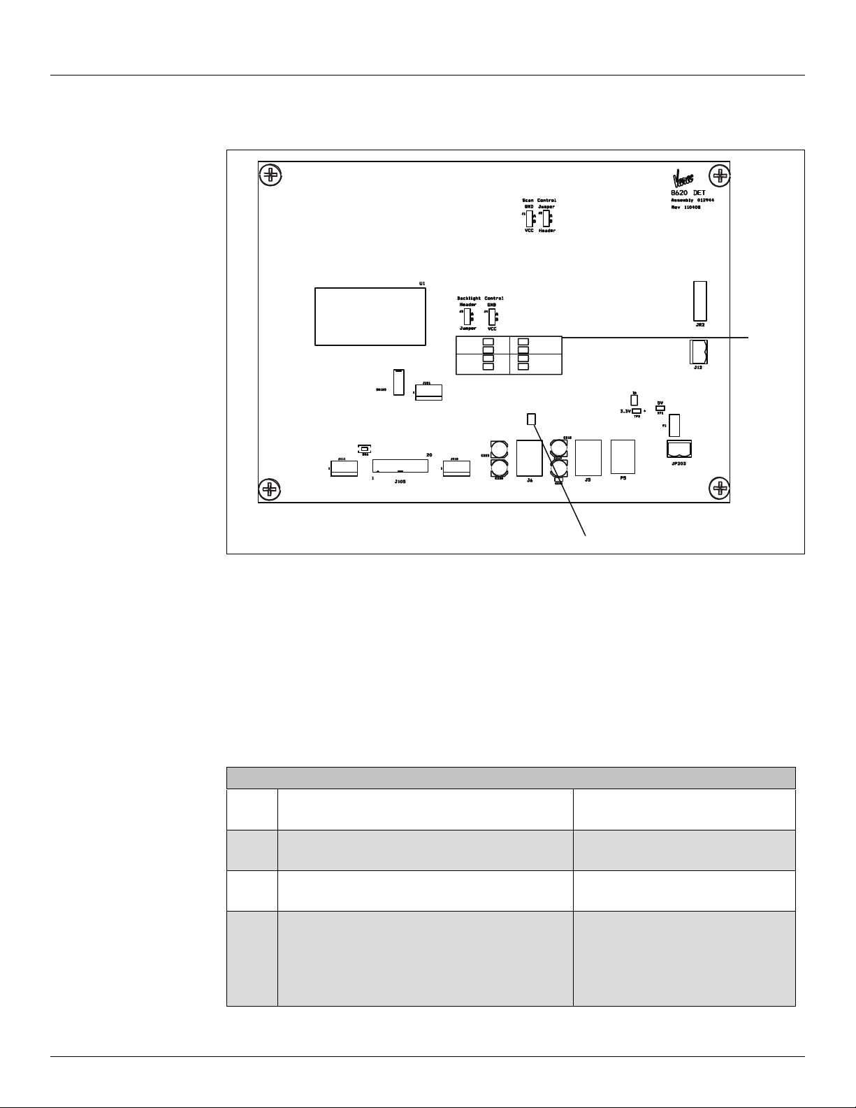
5.2 Troubleshooting
LEDs
Switch 7
SW7
D5
D7
D8
D9
D1
D2
D3
D4
Port 3
Port 4
Port 1
Port 2
8620 Driver Entry Terminal
Figure 5-2: LEDs and Switch 7 on the Varec Interface Board
5.2.1 Using Local Diagnostics (LED Indicators)
Refer to Figures 5-2 to locate the 8620 DET Switch 7 (SW7) and LED indicators.
1. If SW7 is up, Port 4 is available as a USB port.
2. If SW7 is down, Port 4 is used for the keyboard.
3. LED D6 is the power indicator switch.
4. Monitor the LED indications as described below:
LED Purpose Description
D1
D2
D3
D4
D5
D7
D8
D9
------
D8
D9
Port 1 Green: Good USB Status
Port 2 Green:Good USB Status
Port 3 Green: Good USB Status
Port 4 = USB Port
(SW7 is up)
--------------------------------------------
Port 4 = Keyboard
(SW7 is down)
Amber: USB Malfunction
Amber: USB Malfunction
Amber: USB Malfunction
Green: Good USB Status
Amber: USB Malfunction
---------------------------------
Green: Good Keyboard Status Amber:
Keyboard Malfunction
Table 5-2: 8620 LEDs and Switches for Troubleshooting
Varec, Inc. 21
Page 30
Maintenance and Troubleshooting
5.2.2 Replacing the main circuit fuse
1. Turn off the main circuit breaker switch to remove power from the unit.
2. Open the front panel of the 8620 DET.
3. Open the fuse holder to release the fuse.
4. Remove the fuse on the main circuit board from the fuse holder. To locate the fuse holder,
5. Replace it with a new fuse (part # P116-01-044).
6. Close the front panel of the 8620 DET.
7. Turn on the main circuit breaker to connect power to the unit.
Table 5-3 lists the type of fuse and the fuse value.
5.2.3 Replacing the I/O Module fuse on the OPTO 22 board
! Warning Explosion Hazard. T o prevent an electrical shock or ignition of a flammable atmosphere,
do not remove or replace the main circuit board fuse while the circuit is live.
refer to Figures 3-1 and 3-2 on pages10 and 11.
! Warning Explosion Hazard. T o prevent an electrical shock or ignition of a flammable atmosphere,
do not remove or replace the I/O Module fuse on the OPTO 22 board while the circuit
is live.
If the digital I/O has a module with a fuse, do the following to replace the fuse:
1. Turn off the main circuit breaker switch to remove power from the unit.
2. Open the front panel of the 8620 DET.
3. Open the fuse holder to release the fuse.
4. Remove the fuse on the I/O Module from the fuse holder. To locate the fuse holder on the
I/O Module, refer to Figures 3-1 and 3-2 on pages10 and 11.
5. Replace it with a new fuse (part #
37411000410).
6. Close the front panel of the 8620 DET.
7. Turn on the main circuit breaker to connect power to the unit.
Table 5-3 lists the type of fuse and the fuse value.
Fuse Fuse Value Part # Description
Main Fuse 1 Amp 600 VAC, 300 VDC P116-01-044 Cooper Busman Fuse
I/O Module Fuse 1 Amp 250V 37411000410 Wickman 374 Series TRS5®
Subminiature Fuse
Table 5-3: Fuse, Fuse Value, Part #, and Description
22 Installation and Operations Manual
Page 31
5.2.4 Replacing the Battery
! Warning There is a danger of a new battery exploding if it is incorrectly installed. Do not
attempt to recharge, force open, or heat the battery. Replace the battery only with the same
or equivalent type recommended by the manufacturer. Discard used batteries according to
the manufacturer’s instructions
Table 5-4 lists the battery, type, and part number for the CPU board battery.
Battery Type Part Number
CPU Board Battery Lithium 3V / 196 mAH BR1632
Table 5-4: CPU Board Battery Fuse, Type, and Part Number
8620 Driver Entry Terminal
Varec, Inc. 23
Page 32
Maintenance and Troubleshooting
8620 Voltage
Monitor LED
8620 DET
Reset Button
5.2.5 8620 DET Voltage Monitor
The voltage monitor monitors the input voltage and detects whether the voltage is low or below
an acceptable level (for DC units only). The voltage monitor LED indicates the different states of
the input voltage (see Table 5-5 below).
For AC units, the LED indicates that power is supplied to the unit.
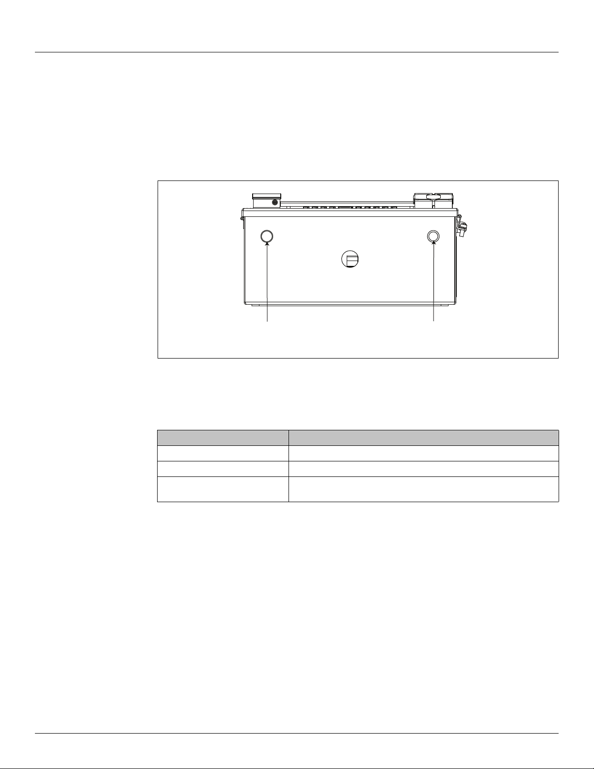
Figures 5-3 shows the location of the 8620 DET voltage monitor LED.
Figure 5-3: 8620 DET Voltage Monitor LED and Reset Button Locations
Table 5-5 lists the input voltage and the state of the LED for monitoring the voltage.
Input Voltage LED
Above 23 VDC Solid Green
Approximately 23 VDC - 19 VDC Flashes Green
Below 19 VDC Red (The LED remains Red even if good power is restored).
Table 5-5: Input Voltage and LED State
Note The LED remains Red once the supplied power to the 8620 DET becomes
unacceptable. Contact your Varec representative for more information when the LED is RED.
5.2.6 Resetting the 8620 DET
Note The reset button resets the CPU of 8620 DET, but does not reset the voltage monitor.
To reset the 8620 DET, toggle the reset button shown in Figures 5-3 above.
Contact Varec for more information.
24 Installation and Operations Manual
Page 33

6 Specifications
6.1 General
Manufacturer Varec, Inc. Atlanta, GA USA
Designation 8620 Driver Entry Terminal (DET)
Function Field interface device used to control access to different control points
6.2 System Components
8620 Driver Entry Terminal
Single Board
Computer
Interface Four USB 2.0 compliant universal serial bus ports for optional interface
Display 24-bit TFT LCD
Keyboard • Vandal resistant (20J BS EN 60068-2-75: 1997)
Voltage Monitor Indicates the status of the DC supply voltage on DC-powered units and the
• Expansion Interface: PC/104
• Battery backup: Lithium 3V/196 mAH
• Four serial ports for host communications
• Four USB 2.0 compliant universal serial bus ports for internal devices,
configuration or optional components. One USB port is always reserved to
facilitate communications between the Varec Interface Board and the Single
Board Computer.
• Solid State Disk (SSD): Supports one 50-pin socket for CFC type (type II
optional)
• Supports up to four GPIO - uses standard I/O modules
• 9 LEDs indicate power and status
components. e.g Use of the keyboard requires reservation of a USB port.
• Weather resistant (IP65)
• 53-Key alphanumeric
•Engraved metal keys
• RFI/EMI Protection in accordance with European and U.S. directives
• Resistant to most commonly used cleaning agents
presence of AC power on AC-powered units.
Varec, Inc. 25
Page 34
Specifications
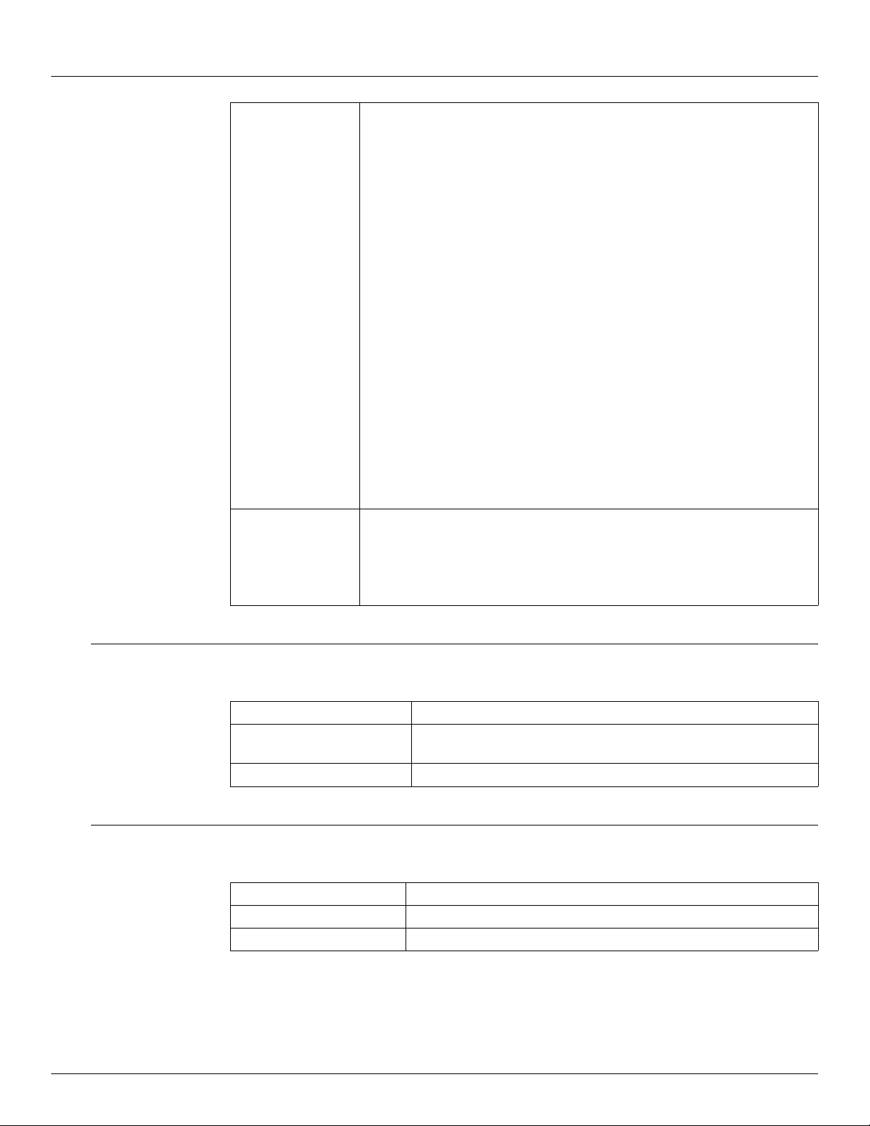
Smart Card Reader • Dual reader technology:
•iCLASS
•Proximity
• 64-bit authentication keys
• Programmable LED/Beeper operation
• Read Range is dependant upon which card is used:
•Min. 1.0" (2.5 cm) To Max. 4.0" (10.0 cm)
• Card Compatibility:
125 kHz Proximity:
•HID or Indala proximity cards, keyfobs, and tags
•AWID Credentials
13.56 MHZ contactless smart cards:
•ISO 15693 — read only; 2k bit (256 byte), 16k bit (2k byte), and 32k bit (4k
byte); serial number
•ISO 14443A — read only; MIFARE and DESFire® (serial number)
•ISO 14443B — read only; 2k bit (256 byte), and 16k bit (2k byte)
•US Government PIV
•FeliCa IDm
•Certifications:
•FCC Certification
•CE Mark
• Housing Material: UL94 Polycarbonate
Fingerprint Scanner • Supports TWIC applications
• Waterproof
• 12.8 mm X 12.0 mm active sensing area
• Aluminum construction with commercial grade power coat finishing
• Performs solid 1:1 verification and 1:N identification
6.3 Host Communication
Serial Ports 4
Communications type Com 1, Com 3, and Com 4: RS-232
Ethernet 2
6.4 Environmental
Operating Temperature From -40 °C To 70 °C Ambient (From -40 °F To 158 °F Ambient)
Storage Temperature From -40 °C To 70 °C (From -40 °F To 158 °F)
Humidity 5 - 95% non-Condensing at 0 °C To 55 °C (32 °F To 131 °F)
Com 2: RS-485/422 or RS-232
26 Installation and Operations Manual
Page 35
6.5 Electrical
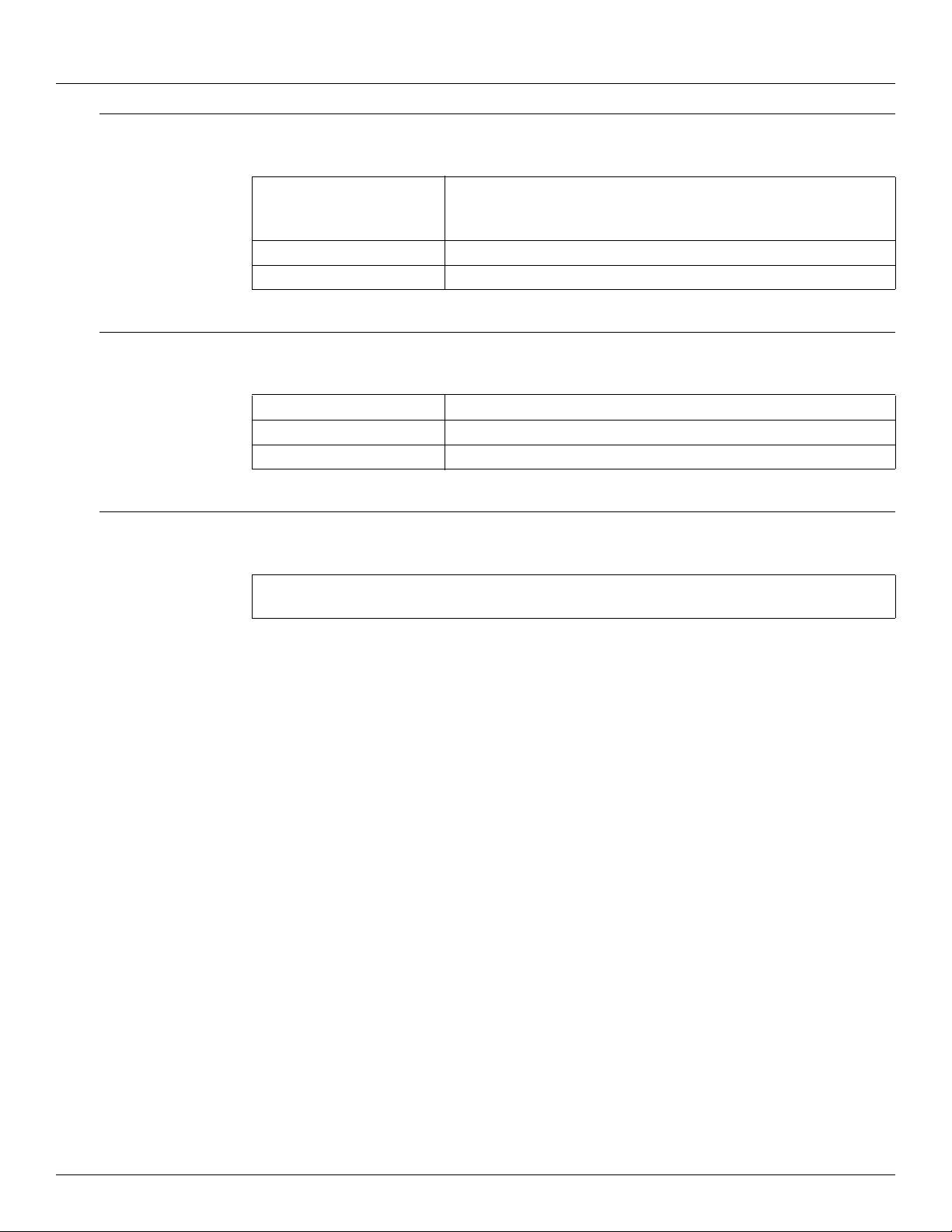
Operating Voltage AC or DC
Power Consumption DC • 1A @ 24 VDC
Power Consumption AC • 175mA @ 110 VAC
6.6 Mechanical Construction
Enclosure Type Rated NEMA 3R
Material 1/16” Thick Stainless Steel (1.5875 mm)
Dimensions 17.50" x 14.28" x 6.44" (445 x 363 x 164 mm)
8620 Driver Entry Terminal
• 24 – 48 VDC
• 100 – 240 VAC line to neutral 50/60 Hz
6.7 Certifications and Approvals
FM Approvals (cFMus) Class I, Division 2, Groups C and D, T4
Class I, Zone 2, T4
Varec, Inc. 27
Page 36

Specifications
28 Installation and Operations Manual
Page 37
7 Ordering Information
7.1 Order Codes
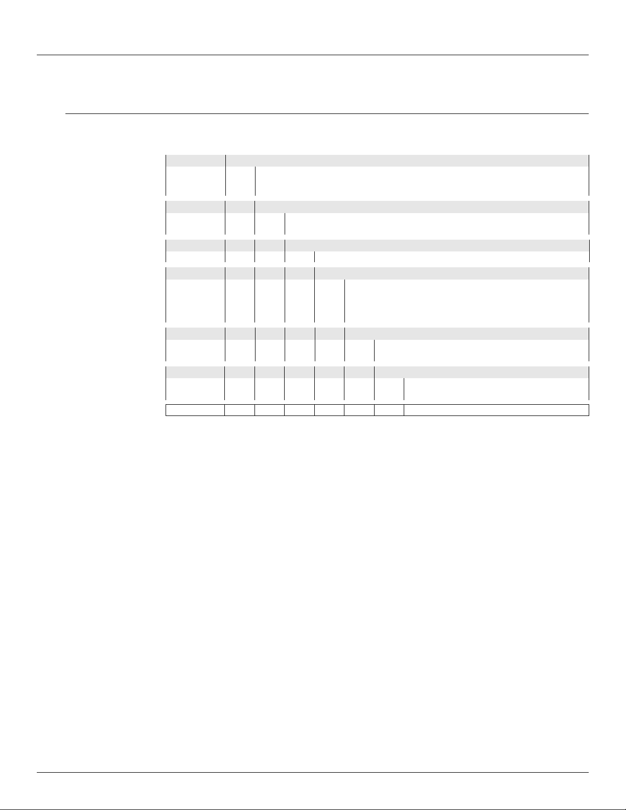
N8620- Complete Product Designation
Data Entry Terminal
Approvals
FM Factory Mutual Approvals (cFMus)
Class I, Division 2, Groups C and D, T4
Class I, Zone 2, T4
Power Supply - Input
1 DC
2 AC
Enclosure Heater
A None
Digital I/O
0 None
1 Single Dry Contact Output
2 Single DC Output
9 Custom Configuration
Card Reader
A None
B FIPS Compliant Smart Card Reader
Fingerprint Scanner
0 None
1 FIPS Compliant USB Fingerprint Scanner
Varec, Inc. 29
Page 38

Ordering Information
30 Installation and Operations Manual
Page 39

Page 40

Document Code
IOM097GVAE4012
Varec, Inc. • 5834 Peachtree Corners East, Norcross (Atlanta), GA 30092 USA
Tel: +1 (770) 447-9202 • Fax: +1 (770) 662-8939
© 2006 Varec, Inc. All Rights Reserved. This docum ent is fo r infor matio n purp oses onl y. Varec, I nc. make s no warr anties, e xpress or implied, in this summary. The names
of actual companies and products mentioned herein may be the trademarks of their respective owners.
www.varec.com
 Loading...