

Vantage Point SATP User Manual
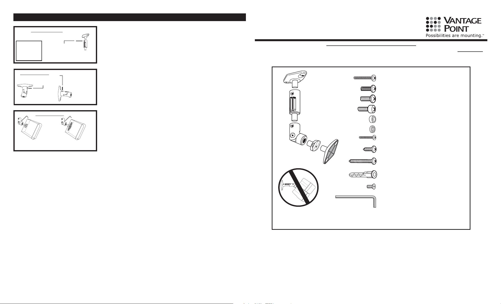
Extension Mounting
Ceiling or Shelf Application Only!
Do not use
extension in
wall mounted
applications
(L)
tighten allen screw using
allen key provided
Step 3. Installation of Extension and Link Set
Install 2-1/2” extension portion of speaker mount to wall plate. Secure the allen set screw enough to hold
extension in place with the weight of the speaker attached.
Model SATP Satellite Speaker
Mount Assembly Instructions
IMPORTANT CONSIDERATIONS PRIOR TO INSTALLATION
Preview all steps before beginning. Should any portion of these instructions be unclear, contact us at 800-582-9595 for assistance. Do Not Attempt to
install this speaker mount if you have any doubts as to its proper installation. This speaker mount is specifically designed for mounting small surround
style speakers weighing 8 lbs. or less. Use of this speaker mount for any other purpose unless specified by the manufacturer is not recommended.
Before you begin, separate the speaker mount parts by loosening the set screws with the supplied allen wrench and simply twist apart.
Link Set Mounting
All Applications
(L)
Speaker Mounting
(L)
post style speaker
plate
(L)
2 hole speaker
tighten allen
screw using allen
key
provided
(L)
plate
Install link set portion of speaker mount to wall plate or 2-1/2” extension. Secure the allen set screw enough
to hold assembly in place with the weight of the speaker attached.
Install speaker with speaker post or 2 hole plate attached. Secure the allen set screw enough to
hold assembly in place with the weight of the speaker attached. Adjust to desired
angle and secure.
Exploded View
Speaker / Wall Plate (4)
2-1/2” Extension (2)
Link Set (2)
(assembled at factory)
Speaker Post (2)
Speaker / Wall Plate (4)
Do not use extensions
in wall mounted
applications
A - M5 x 20mm machine screw (2)
B - 8-32 x 5/8” machine screw (2)
C - 1/4”-20 x 1/2” machine screw (4)
D - 1/4”-20 x 7/8” machine screw (2)
E - M5 x 1/8” plastic washer (2)
F - 8-32 round key hole nut (2)
G - #8 x 3/4” self tapping screw (2)
H - #12 x 3/4” self tapping screw (4)
I - #12 x 1-3/4” self tapping screw (4)
J - #12-14 TOGGLER® ALLIGATOR
plastic anchor (4)
K - M4 x 8mm flat head
machine screw (2)
L - 5/32” allen wrench (1)
“TOGGLER is a registered trademark of Mechanical Plastics Corp.” ALLIGATOR® ANCHOR
“Patented under US Patent numbers 4,181,061; 4,752,170 and 5,161296 and foreign counterparts thereof. Other patents pending.”
Maximum Speaker Weight: 8 lbs
All Vantage Point Products Corp. products are manufactured to ensure superior quality, performance and durability for a lifetime of use . Warranty covers
the product to be free of defects in materials and workmanship under normal and reasonable use. Vantage Point Products will repair or replace, at our
option, any product which proves to be defective upon our inspection. This warranty will not apply to products that have been lost or damaged by misuse,
abuse or accident, altered or repaired in any way or by any person or fi rm other than specifi ed by us, used in violation of instructions or incorrect assembly
nor used in a manner other than specifi ed by us. This warranty is nontransferable to a new owner and may require proof of purchase. All claims must be
directly handled with Vantage Point Products Corp. by calling us at 1-800-582-9595.
WARRANTY INFORMATION
Vantage Point Products Corp • P.O. Box 2485 Santa Fe Springs, CA 90670 USA
USA Tel: 1.800.582.9595 • Canada Tel: 905.607.9994 • Europe Tel: 31.72.581.6056
Web Site: www.vanptc.com • Email: cons-serv@vanptc.com
6i33-08/05
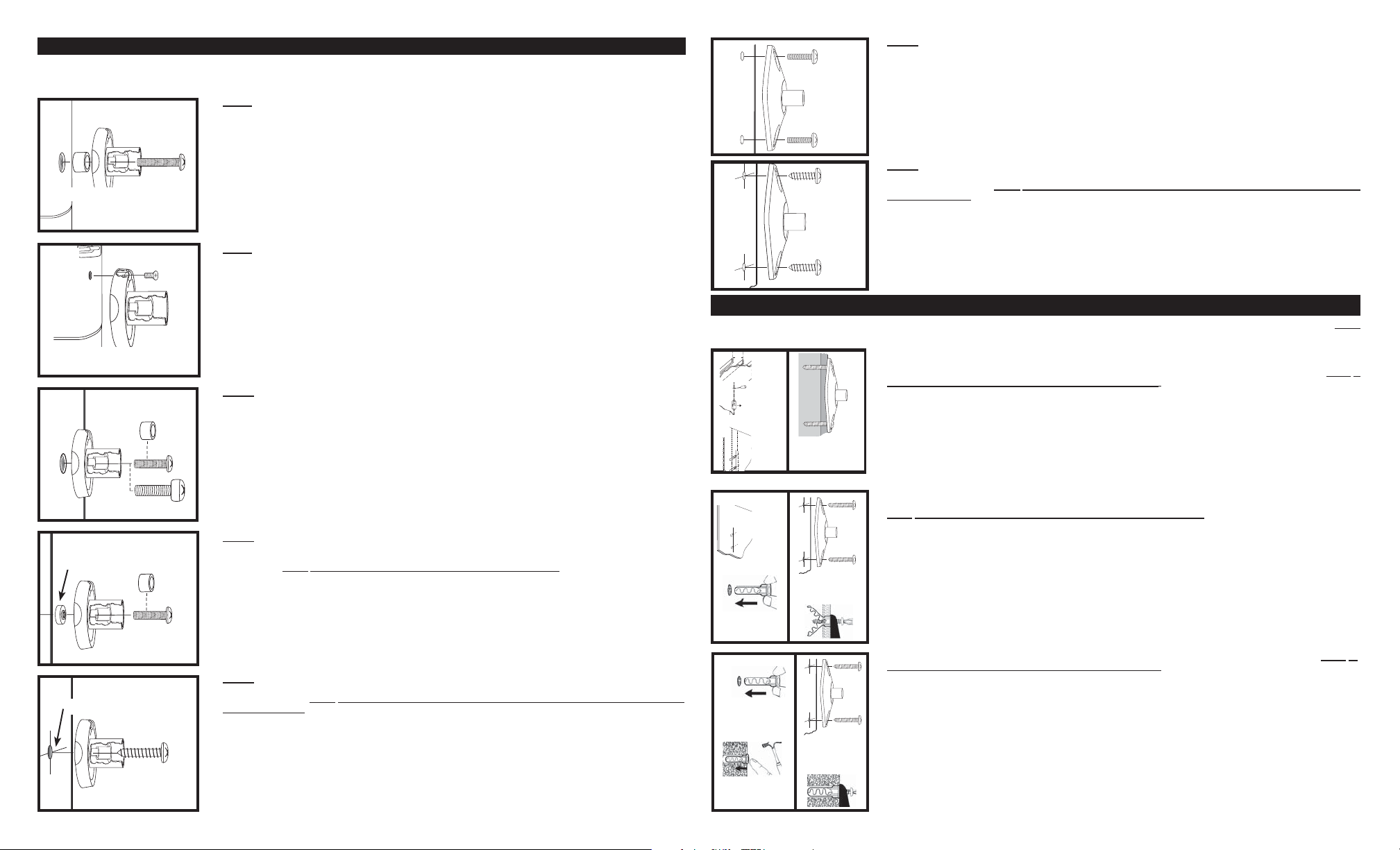
Step 1. Installation of Speaker Post or Speaker Plate
Supplied are parts and hardware for mounting to various manufacturers speakers. You will need to select the type that best suits your application. If the hardware
provided does not fit your speaker you will need to acquire the appropriate hardware.
TYPE 1. POST MOUNT BOSE® SPEAKERS
Factory Installed Threaded Insert
Most BOSE® satellite speakers will require the use of the M5 x 20mm machine screw (A) used in combination with the M5 x 1/8” plastic
(E)
Fig. 1
BOSE® Satellite Speakers
Fig. 2
BOSE® LIFESTYLE® and
ACOUSTIMASS® Speakers
Fig. 3
(A)
(K)
(E)
(B)
washer (E). (see Fig. 1). The plastic washer is used as a spacer between the threaded insert and the speaker mount post. It is critical the
M5 plastic washer is used correctly, otherwise the threaded insert may pull out from the speaker housing. Once proper configura-
tion is determined, secure post to speaker. Proceed to step 2.
TYPE 2. POST MOUNT BOSE® LIFESTYLE® or BOSE® ACOUSTIMASS® Speakers
Utilize the M4 x 8mm flat head machine screw (K) as shown in (Fig. 2) Proceed to step 2.
TYPE 3. POST MOUNT Factory Installed Threaded Insert.
Type 3 instructions are for use with all other speakers with a pre-threaded hole in the back of the speaker. Check the size of
the hole and see if the 8-32 x 5/8” machine screw (B) or the 1/4”-20 x 1/2” machine screw (C) or the 1/4”-20 x 7/8” (D) or the
M5 x 20mm machine screw (A) fits inside. Which ever one fits, put the screw through the speaker post and attach post to the
back of the speaker. If screw does not tighten properly, you will need to use the M5 x 1/8” plastic washer (E) to take up the
slack. Once the proper configuration is determined, secure the post to speaker and Proceed to step 2.
TYPE 6. SPEAKER PLATE 2 or 4 Factory Installed 1/4”-20 Threaded Inserts.
(C)
Find the best mounting configuration that matches your speaker. Four hole speaker mount patterns can be accommodated by
positioning the speaker plate diagonally (see Fig. 6) Using the 1/4”-20 x 1/2” machine screws (C) install the speaker plate and
secure to speaker cabinet.
Proceed to step 2.
(C)
TYPE 7. SPEAKER PLATE No Factory Holes, Wood Cabinet.
(For use with speakers weighing 8 lbs. or less) Locate the optimum mounting position for the speaker plate and use it as a
template to mark for drilling. NOTE: You do not want to drill or screw into the speaker where you could possibly damage
internal components. Drill the holes using a 1/8” drill bit. This hole should be drilled no more than 1/2” deep. You can accomplish
this by placing a piece of tape a 1/2” from the end of the drill bit providing you with a guide. After holes are drilled, mount the
speaker plate using the #12 x 3/4” self tapping screws (H). (see Fig. 7) Proceed to step 2.
drill
1/8” dia.
x 1/2”
(H)
deep
hole
(H)
Step 2. Installation of Wall Plate to Wall
Supplied is mounting hardware for 3 different surface applications. You will need to determine what style hardware will work best with your mounting surface. NOTE:
Always use CAUTION when drilling into a wall or ceiling. Make sure you are avoiding all electrical and water lines.
Fig.
8A
Fig.
8B
16 inches
(TYPICAL)
locate
wood
stud
in ceiling
or wall
drill (2)
1/8” dia.
x 1-7/8”
deep
holes
(I)
Fig. 8C
(I)
install mounting plate
using (2) #12 x 1-3/4”
screws into wood stud
SOLID WOOD OR WOOD STUD - Using a stud finder locate the wood stud or framing member. Using a pick or small drill bit
locate the center of the wood stud (see Fig. 8A), be careful doing this as you don’t want to go any wider than the width of the wall
plate (wall plate will cover any extra holes) Using the wall plate as a template mark hole position on mounting surface NOTE: In
wall mounting applications position mounting holes in a vertical pattern. Drill holes through the drywall and into the wood stud
using a 1/8” drill bit. These holes should be drilled 1-7/8” deep. (see Fig. 8B) You can accomplish this by placing a piece of tape
1-7/8” from the end of the drill bit providing you with a depth guide. After holes are drilled, mount the wall plate using the #12 x
1-3/4” self tapping screws (I). (see Fig. 8C) Proceed to step 3.
(D)
keyhole
(F)
drill 3/32” dia. x 1/2” deep hole
(E)
(B)
(G)
TYPE 4. POST MOUNT Key Hole Design.
If your speaker has a factory key hole design you will use the 8-32 x 5/8” machine screws (B) in combination with the 8-32
round key hole nut (F). Loosely pre-assemble the speaker mount post with the 8-32 x 5/8” machine screw (B) and key hole
nut (see Fig. 4) NOTE: Be sure key hole nut is installed with knurled edge toward post. Engage the key hole nut into key
hole slot as pictured. Put tension on the assembly by gently pulling back on speaker mount post while tightening the 8-32 x
5/8” machine screw (B). The key hole nut will engage on housing in key hole slot. If the post does not tighten securely against
the speaker housing, it will be necessary to use the M5 x 1/8” plastic washer (E) as a spacer under the head of the 8-32 x 5/8”
machine screws (B). (see Fig. 4) Once proper configuration is determined, secure post to speaker. Proceed to step 2.
If the speaker has a screwed on metal keyhole plate you may remove it and install post as shown in TYPE 4.
TYPE 5. POST MOUNT No Factory Holes, Wood Cabinet.
(For use with speakers weighing 8 lbs. or less) Locate the optimum mounting position for the post and mark through the center
of the post for drilling. NOTE: You do not want to drill or screw into the speaker where you could possibly damage
internal components. Drill a single hole using a 3/32” drill bit. This hole should be drilled no more than 1/2” deep. You can
accomplish this by placing a piece of tape a 1/2” from the end of the drill bit providing you with a guide. After hole is drilled,
mount the post using the #8 x 3/4” self tapping screw (G). (see Fig. 5) Proceed to step 2.
Fig. 9A
Fig. 9B
Insert Toggler Alligator
Fig. 10A
Fig. 10B
drill (2)
5/16” dia.
x 1-7/8”
deep
holes
(J)
anchor into wall.
(J)
Insert Toggler Alligator
anchor into concrete
wall or ceiling.
hammer insert into
media until flush with
surface.
Fig.
9C
(I)
(I)
Insert #12 x 1-3/4”
screw through wall
plate into anchor.
(I)
Fig.
10C
(I)
(I)
Insert #12 x 1-3/4”
screw through wall
plate into Alligator™
anchor.
(I)
HOLLOW DRYWALL SURFACE - Locate best mounting location in the ceiling or wall. Using the wall plate as a template mark
hole position on mounting surface.
NOTE: In wall mounting applications position mounting holes in a vertical pattern. Drill holes in the drywall using a 5/16”
drill bit (see Fig. 9A). Once holes are drilled insert the #12-14 TOGGLER® ALLIGATOR anchors (J) into the holes making sure
anchor is flush with wall or ceiling surface. (see Fig. 9B) With TOGGLER® ALLIGATOR anchors in place, mount the wall plates
using the #12 x 1-3/4” self tapping screws (I). (see Fig. 9C)
Proceed to step 3.
SOLID CONCRETE OR HOLLOW BLOCK - Using the wall plate as a template mark hole position on mounting surface. NOTE: In
wall mounting applications position mounting holes in a vertical pattern. Drill holes in the solid concrete or hollow block using
a 5/16” masonry drill bit. Once holes are drilled insert the #12-14 TOGGLER® ALLIGATOR anchors (J). (see Fig. 10A) into
the holes making sure anchor is flush with wall or ceiling surface. (see Fig. 10B) With TOGGLER® ALLIGATOR anchors in
place, mount the wall plate using the #12 x 1-3/4” self tapping screws (I). (see Fig. 10C) Proceed to step 3.
 Loading...