

Page 1
Three, Four and Five Shelf
Glass Rack Assembly Instructions
IMPORTANT : PLEASE READ FIRST
Steps for the Three, Four and Five shelf Audio/Video stand are the same. It is advisable to perform assembly
on a clean flat surface . The unit must be assembled up-side down and then carefully turned over after
completing step 4. Should any portion of these instructions be unclear, call our customer service at
800-582-9595
Maximum Weight Ratings
3 Shelf Glass 250 lbs
4 Shelf Glass 125 lbs
5 Shelf Glass 125 lbs
WARRANTY INFORMATION
No Warranty on Glass. All V antage Point products are
manufactured to ensure superior quality, performance
and durability for a lifetime of use. Warranty covers the
product to be free from defects in materials and workmanship under normal and reasonable use. Vantage
Point Products Corp. will repair or replace, at our
option, any product which proves to be defective upon
our inspection. This warranty will not apply to products
that have been lost or damaged by misuse, abuse or
accident, altered or repaired in any way or by any
person or firm other than specified by us, used in
violation of instructions or incorrect assembly nor used
in a manner other than specified by us. The warranty is
nontransferable to a new owner and may require proof
of purchase. All claims must be directly handled
with Vantage Point Products Corp.
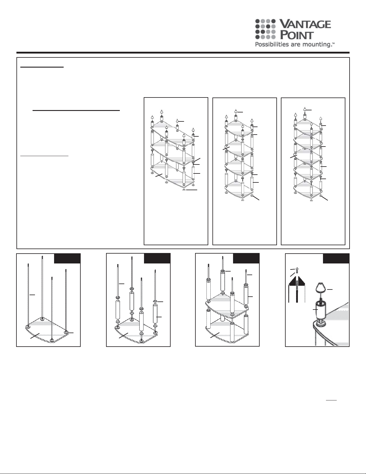
3 SHELF
A
E
F
D
H
(inverted for assembly)
A Foot cone 6
B Spikes 6
C Jam nuts for spikes 6
D Threaded rod 22.275” 6
E 2-3/4” tubes 6
F Plastic spacers 30
G 9” tubes 12
H Glass shelves 3
I Buttons 6
G
I
4 SHELF
A
E
F
H
H
D
G
(inverted for
assembly)
A Foot cone 4
B Spikes 4
C Jam nuts for spikes 4
D Threaded rod 31.605” 4
E 2-3/4” t ubes 4
F Plastic spacers 28
G 9” tubes 12
H Glass shelves 4
I Buttons 4
I
(inverted for
assembly)
A Foot cone 4
B Spikes 4
C Jam nuts for spikes 4
D Threaded rod 30.935” 4
E 2-3/4” t ubes 4
F Plastic spacers 36
G 6-1/2” tubes 16
H Glass shelves 5
I Buttons 4
5 SHELF
A
E
F
G
D
I
Step 1
D
I
H
Locate the glass shelf (H), then
position the threaded button (I)
hole face up, under the glass
shelf (H) and align with the holes
in the glass shelf (H). Install the
threaded rods (D) into the the
threaded buttons (I). Note: Do not
over tighten.
Vantage Point Products Corp. • P.O. Box 2485, Santa Fe Springs, CA 90670
U.S.A. Tel: 800-582-9595 • Canada Tel: 905.607.9994 • Web Site: www .vanptc.com • Email: [email protected]
Step 2
D
F
G
H
Once all of the threaded rods
(D) are installed, slide the plastic
spacers (F) onto the threaded
rods (D). Make sure the small
hole end with the lip is facing
downward, this lip will engage into
the hole in the glass shelf (H). The
large diameter end will engage
into the tubes. Next slide one each
of the long tubes (G) down each of
the steel rods (D). Tubes should
engage onto the plastic spacers
(F). Again slide one plastic spacer
(F) down each threaded rod (D)
with small hole up.
Step 3
F
H
Install the next glass shelf(H) carefully over the threaded rods (D).
Align on the previously installed
plastic spacers (F). Slide one plastic spacer (F) down each threaded
rod (D) small hole down. Align
the plastic spacers (F) into the
holes on the glass shelf (H). Slide
one long tube (G) down each of
the threaded rods (D) and align
on the plastic spacers (F). Again
slide a plastic spacer (F) down
each threaded rod (D) small hole
up, engage into the long tubes
(G). Repeat this procedure for the
remaining shelves.
D
G
Step 4
Optional Spikes included
C
for carpeted floors.
B
A
E
After placing the last glass shelf
(H) on top, install the plastic spacers (F) small hole down. Locate
the 2-3/4” tubes (E) and install
one onto each threaded rod (D).
Screw the foot cones (A) down
onto the exposed threaded rods
(D). Tighten the cones (A) by
rotating the 2-3/4” tubes and the
foot cones together. Note: Make
sure all plastic spacers are properly engaged in both shelves and
tubes before final tightening. Install
optional rubber tips or spikes w/
jam nuts. Turn unit upright.
6i17-02/07
 Loading...