

Page 1
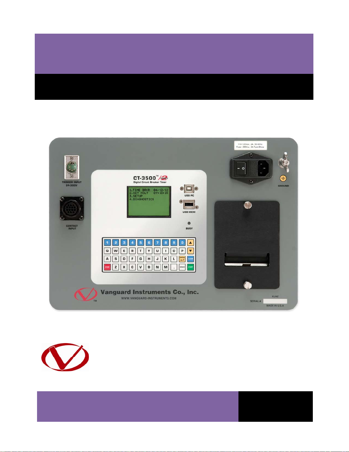
CT-3500 S2
Digital Circuit Breaker Timer
USER’S MANUAL
Vanguard Instruments Company, Inc.
1520 S. Hellman Ave.
Ontario, California 91761, USA
TEL: (909) 923-9390
FAX: (909) 923-9391
July 2012
Revision 1
Page 2

CT-3500 S2 USER’S MANUAL REV 1
SAFETY SUMMARY
FOLLOW EXACT OPERATING PROCEDURES
Any deviation from the procedures described in this User’s Manual may create one or more
safety hazards, may damage the CT-3500 S2, or cause errors in the test results. Vanguard
Instruments Company, Inc. assumes no liability for unsafe or improper use of the CT-3500 S2.
All safety precautions provided in this manual must be observed during all phases of testing
including test preparation, test lead connection, actual testing, and test lead disconnection.
SAFETY WARNINGS AND CAUTIONS
Only trained operators shall use the CT-3500 S2. All devices under test shall be off-line and fully
isolated. Do not perform test procedures or service alone.
DO NOT MODIFY TEST EQUIPMENT
To avoid the risk of introducing additional or unknown hazards, do not install substitute parts or
perform any unauthorized modification to any CT-3500 S2 test unit. To ensure that all designed
safety features are maintained, it is highly recommended that repairs be performed only by
Vanguard Instruments Company factory personnel or by an authorized repair service provider.
Unauthorized modifications can cause safety hazards and will void the manufacturer’s
warranty.
WARNING
Do not remove test leads during a test. Failure to heed this warning can result in electrical
shock to personnel and damage to the equipment.
i
Page 3

REV 1 CT-3500 S2 USER’S MANUAL
TABLE OF CONTENTS
CONVENTIONS USED IN THIS DOCUMENT ..................................................................................... 1
1.0 INTRODUCTION .................................................................................................................. .. 2
1.1 General Description and Features ................................................................................... 2
1.2 Technical Specifications ................................................................................................... 3
1.3 CT-3500 S2 Controls and Indicators ................................................................................. 4
2.0 PRE-TEST SETUP ................................................................................................................... 5
2.1 Operating Voltages .......................................................................................................... 5
2.2 LCD Screen Contrast Control ............................................................................................ 5
3.0 OPERATING PROCEDURES ................................................................................................... 6
3.1 Connection Diagrams ....................................................................................................... 6
3.3 Setting the Frequency ...................................................................................................... 9
3.4 Using a PC to Retrieve Test Shots from the CT-3500 S2 ................................................ 10
3.5 Testing Procedures ........................................................................................................ 12
3.5.1. Entering Test Record Header Information ............................................................. 12
3.5.2. Timing an OPEN Operation ..................................................................................... 15
3.5.3. Timing a CLOSE Operation ...................................................................................... 18
3.5.4. Timing an OPEN-CLOSE Operation ......................................................................... 21
3.5.5. Timing a CLOSE-OPEN Operation ........................................................................... 24
3.5.6. Timing a Special OPEN Operation .......................................................................... 27
3.6 Working With Test Shots ............................................................................................... 30
3.6.1. Viewing the Contents of the Working Memory ..................................................... 30
3.6.2. Saving Test Results to a Test Shot .......................................................................... 32
3.6.3. Restoring a Test Shot From Flash EEPROM ............................................................ 34
3.6.4. Restoring a Test Shot From a USB Flash Drive ....................................................... 37
3.6.5. Copying Test Records to a USB Flash Drive ............................................................ 39
3.6.6. Printing the Test Record Directory ......................................................................... 42
3.6.7. Erasing Test Records from the Flash EEPROM ....................................................... 44
3.7 Performing Cable Diagnostics ........................................................................................ 47
4.0 Getting the Latest Firmware, Software, and Manuals....................................................... 48
ii
Page 4

CT-3500 S2 USER’S MANUAL REV 1
LIST OF TABLES
Table 1. CT-3500 S2 Technical Specifications ................................................................................. 3
LIST OF FIGURES
Figure 1. CT-3500 S2 Controls and Indicators ................................................................................. 4
Figure 2. Typical CT-3500 S2 Connection Diagram (Trigger Cable with 4 Leads) ........................... 6
Figure 3. Typical CT-3500 S2 Connection Diagram (Trigger Cable with 3 Leads) ........................... 7
Figure 4. Sample OPEN Test Results Printout ............................................................................... 17
Figure 5. Sample CLOSE Test Results Printout .............................................................................. 20
Figure 6. Sample OPEN-CLOSE Test Results Printout ................................................................... 23
Figure 7. Sample CLOSE-OPEN Test Results Printout ................................................................... 26
Figure 8. Sample Special OPEN Test Results Printout ................................................................... 29
iii
Page 5
REV 1 CT-3500 S2 USER’S MANUAL
CONVENTIONS USED IN THIS DOCUMENT
This document uses the following conventions:
• A key, switch, or knob on the CT-3500 S2 is indicated as [KEY], [SWITCH], [KNOB].
Menu options are referenced as (MENU OPTION).
•
• The terms “test record” and “test shot” are used interchangeably.
• CT-3500 S2 screen output is shown as:
1. OPTION 1
2. OPTION 2
3. OPTION 3
4. OPTION 4
5. OPTION 5
• When instructions are provided, the menu item that should be selected is shown in bold as
shown below (option 3 should be selected):
1. OPTION 1
2. OPTION 2
3. OPTION 3
4. OPTION 4
5. OPTION 5
• Warning messages are indicated as:
Warning message
WARNING
• Important notes are indicated as:
Note details
NOTE
1
Page 6

CT-3500 S2 USER’S MANUAL REV 1
1.0 INTRODUCTION
1.1 General Description and Features
The CT-3500 S2 is Vanguard’s second generation, stand-alone, digital, microprocessorcontrolled, circuit-breaker timer. It measures the elapsed time from the instant a breaker coil is
energized to the instant of opening or closing of a circuit-breaker’s dry contacts. In addition to
timing a breaker’s contact response time, the CT-3500 S2 can also time relays or other
switching functions that use an initiating trigger voltage (24-300 Volts DC or AC). The timertriggering voltage starts three independent electronic timers. Each timer is individually stopped
by its respective dry-contact closing or opening. The CT-3500 can fully analyze the timing of all
circuit breaker operations (Open, Close, Open – Close, and Close – Open). Timing results are
displayed in milliseconds and cycles on the unit’s back-lit LCD screen and can be printed on the
built-in 2.5-inch wide thermal printer.
Contact Timing Inputs
The CT-3500 S2 features three dry-contact, timer-channel monitoring inputs. The dry-contact
channels use an isolated 15 Vdc power supply to monitor the circuit breaker contact states. All
inputs are shunted to ground until the instant a test is initiated. All contact timing inputs are
protected against static discharge. A contact self-test cable-mode is also available for testing
cables or connections to the breaker.
User Interface
The CT-3500 S2 features a back-lit LCD screen (128 x 64 pixels) that is viewable in both bright
sunlight and low-light levels. A rugged, 44-key, "QWERTY" membrane keypad is used to control
the unit and input data. The unit's built-in 2.5-inch wide thermal printer can be used to print
test reports.
Internal Test Record Storage
The CT-3500 S2 can store up to 128 test records in Flash EEPROM. Test records can be retrieved
and printed on the built-in thermal printer, or they can be transferred to a PC via the unit’s USB
interface. The USB interface can also be used for diagnostic testing and for updating firmware.
The CT-3500 S2 also features a USB Flash drive interface that can be used to store test records
on an external USB Flash drive. A Windows®-based Circuit Breaker Analysis application is
provided with each unit and can be used to transfer test records to a PC. Test records can also
be reviewed, printed or exported in Excel, PDF, and XML formats for further analysis.
2
Page 7

REV 1 CT-3500 S2 USER’S MANUAL
1.2 Technical Specifications
Table 1. CT-3500 S2 Technical Specifications
TYPE portable circuit-breaker analyzer
PHYSICAL SPECIFICATIONS 16”W x 7”H x 13” D (40.6 cm x 17.4 cm x 33 cm); Weight: 14 lbs. (6.4 Kg)
INPUT POWER 100-240 Vac, 50/60 Hz
DRY-CONTACT INPUT 3 channels
TRIGGER INPUT VOLTAGE open/close: 24-300 V, DC or peak AC
BREAKER OPERATIONS Open, Close, Open-Close, Close-Open
TIMING RESOLUTION ±0.1 millisecond; accuracy: 0.05% of reading ±0.1 ms
DISPLAY back-lit LCD screen (128 x 64 pixels); viewable in bright sunlight and low light
conditions
KEYPAD rugged, 44-key "QWERTY"-style membrane keypad
PRINTER built-in 2.5-inch wide thermal printer
INTERNAL TEST RECORD
STORAGE
COMPUTER INTERFACE one USB PC interface, one USB Flash drive interface
PC SOFTWARE Windows®-based Breaker Analysis software included with purchase price
SAFETY designed to meet IEC61010 (1995), UL61010A-1, CSA-C22.2 standards
ENVIRONMENT Operating: -10°C to +50°C (+15°F to +122°F);
HUMIDITY 90% RH @ 40°C (104°F) non-condensing
ALTITUDE 2,000 m (6,562 ft) to full safety specifications
CABLES furnished with full set of test leads (including 20-foot contact leads, 30-foot
OPTIONS transportation case
WARRANTY one year on parts and labor
stores up to 128 timing records
Storage: -30°C to +70°C (-22°F to +158°F)
contact lead extensions, trigger cable, power cable, and ground cable)
The above specifications are valid at nominal operating voltage and at a
temperature of 25°C (77°F). Specifications may change without prior notice.
NOTE
3
Page 8
CT-3500 S2 USER’S MANUAL REV 1
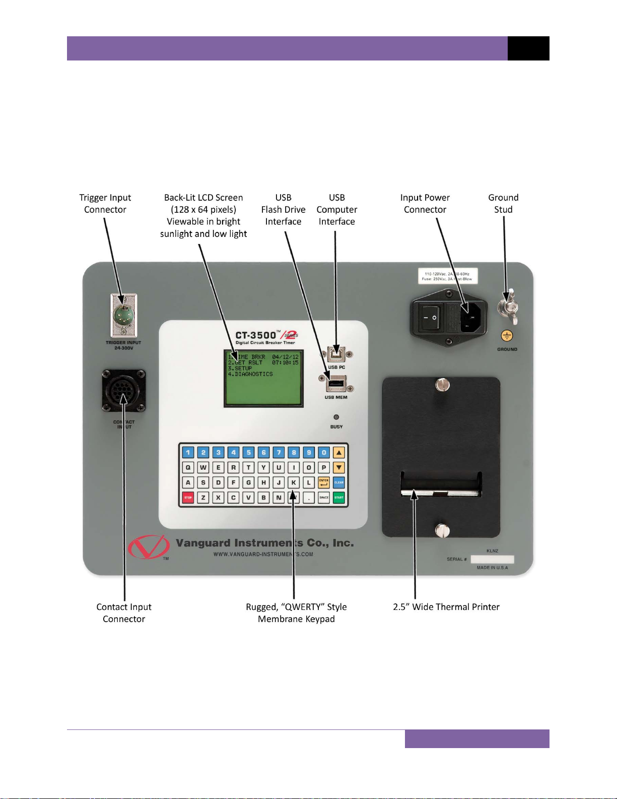
1.3 CT-3500 S2 Controls and Indicators
The CT-3500 S2’s controls and indicators are shown in Figure 1 below. The purpose of the
controls and indicators may seem obvious, but users should familiarize themselves with them
before using the CT-3500 S2. Accidental misuse of the controls will usually cause no serious
harm. Users should also familiarize themselves with the safety summary information found on
the front page of this User’s Manual.
Figure 1. CT-3500 S2 Controls and Indicators
4
Page 9

REV 1 CT-3500 S2 USER’S MANUAL
2.0 PRE-TEST SETUP
2.1 Operating Voltages
The CT-3500 S2 operates on voltages between 100-240 Vac, 50/60 Hz.
2.2 LCD Screen Contrast Control
To increase the LCD screen contrast, press and hold the [∧] key for two seconds. Release the
button when the desired contrast level has been reached.
To decrease the LCD screen contrast, press and hold the [∨] key for two seconds. Release the
button when the desired contrast level has been reached.
2.3 Printer Paper Control
To advance the thermal printer paper, press and release the [∧] key.
To retract the thermal printer paper, press and release the [∨] key.
2.4 Printer Paper
The CT-3500 S2’s built-in thermal printer uses 2.5-inch wide thermal paper for printing test
results. To maintain the highest print quality and to avoid paper jams, the use of thermal paper
supplied by Vanguard Instruments Company is highly recommended. Additional paper can be
ordered from the following sources:
Vanguard Instruments Co, Inc.
1520 S. Hellman Avenue
Ontario, CA 91761
Tel: 909-923-9390
Fax: 909-923-9391
Part Number: VIC TP-3 paper
BG Instrument Co.
13607 E. Trent Avenue
Spokane, WA 99216
Tel: 509-893-9881
Fax: 509-893-9803
Part Number: VIC TP-3 paper
5
Page 10
3.0 OPERATING PROCEDURES
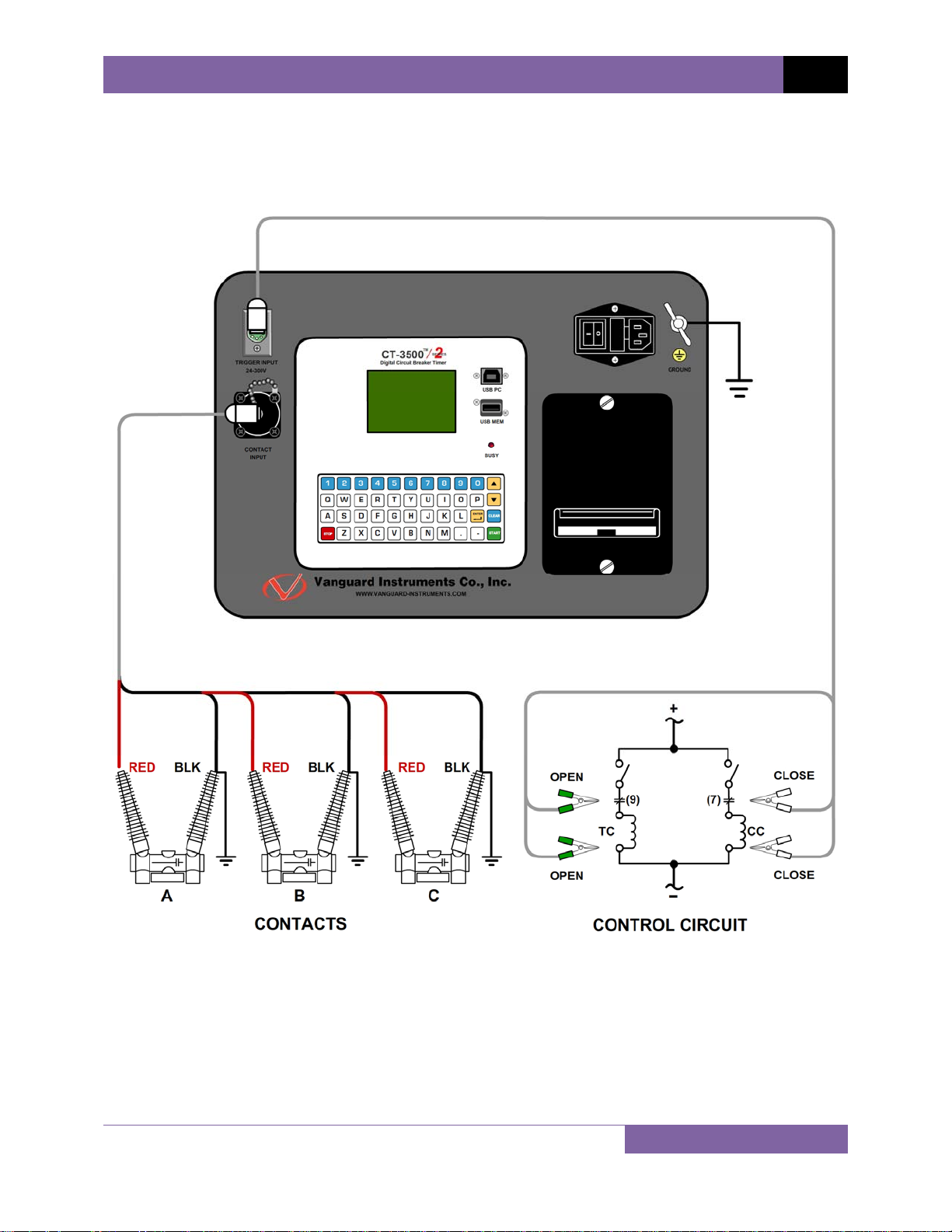
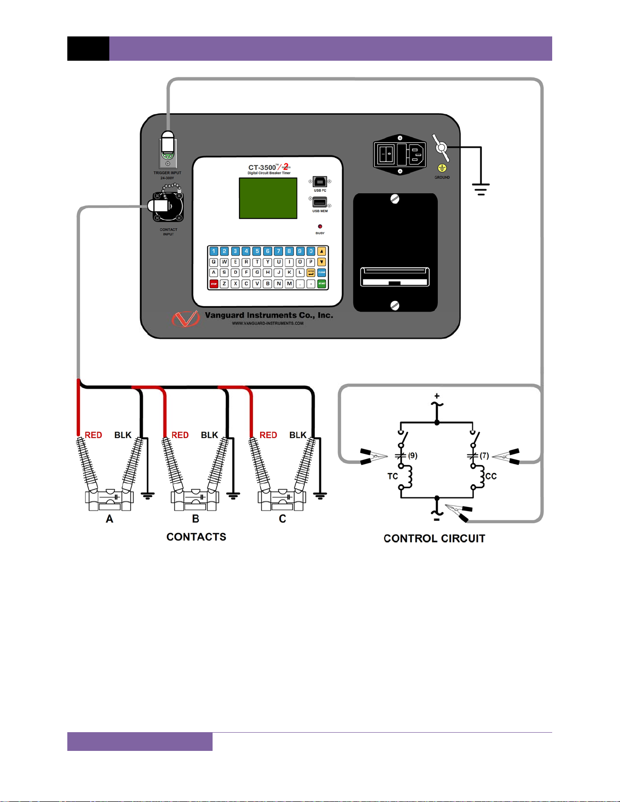
3.1 Connection Diagrams
CT-3500 S2 USER’S MANUAL REV 1
Figure 2. Typical CT-3500 S2 Connection Diagram (Trigger Cable with 4 Leads)
6
Page 11
REV 1 CT-3500 S2 USER’S MANUAL
Figure 3. Typical CT-3500 S2 Connection Diagram (Trigger Cable with 3 Leads)
7
Page 12

3.2 Setting the Date and Time
To set the date and time:
a. Start from the “START-UP” menu:
1. TIME BRKR 05/14/12
2. GET RSLT 08:45:25
3. SETUP
4. DIAGNOSTICS
CT-3500 S2 USER’S MANUAL REV 1
Press the
[3] key (SETUP).
b. The following screen will be displayed:
1. SHOT DESCRIPTION
2. SAVE / RESTORE
3. SET 50/60 HZ
4. SET DATE & TIME
Press the
[4] key (SET DATE & TIME)
c. The following screen will be displayed:
ENTER DATE
MM-DD-YY
Type in the date using the keypad. The following screen will be displayed:
ENTER TIME
HH:MM:SS
Enter the time using the alpha-numeric keypad. When the time has been entered, you
will be immediately returned to the “START-UP” menu.
8
Page 13

REV 1 CT-3500 S2 USER’S MANUAL
3.3 Setting the Frequency
Follow the steps below to set the frequency (50 or 60 Hz):
a. Start from the “START-UP” menu:
1. TIME BRKR 05/14/12
2. GET RSLT 08:45:25
3. SETUP
4. DIAGNOSTICS
Press the
[3] key (SETUP).
b. The following screen will be displayed:
1. SHOT DESCRIPTION
2. SAVE / RESTORE
3. SET 50/60 HZ
4. SET DATE & TIME
Press the
[3] key (SET 50/60 HZ).
c. The following screen will be displayed:
1. SET 50 HZ
2. SET 60 HZ
Select the preferred frequency by pressing the corresponding key on the keypad (
[2]). The frequency will be set and a confirmation screen will be displayed as shown
below:
60 HZ SET
Press any key to return to the “START-UP” menu.
9
[1] or
Page 14
CT-3500 S2 USER’S MANUAL REV 1
3.4 Using a PC to Retrieve Test Shots from the CT-3500 S2
The CT-3500 S2 can be connected to a PC, and test records can be retrieved from the unit using
the included Vanguard Universal Software (VUS, version 2.05 and above). Follow the steps
below to properly connect the CT-3500 S2 and configure the VUS application to recognize the
unit.
a. Install the Vanguard Universal Software.
b. Connect the CT-3500 S2 to the PC by connecting a USB cable from an open USB port on
the PC to the unit’s “USB PC” port.
c. Turn on the power on the CT-3500 S2.
d. If this is the first time you are connecting the unit to the PC, Windows will recognize it as
a new device and automatically install necessary drivers. If using Windows XP, you may
be prompted to install drivers. Select the automatic installation option and Windows will
locate the generic drivers necessary.
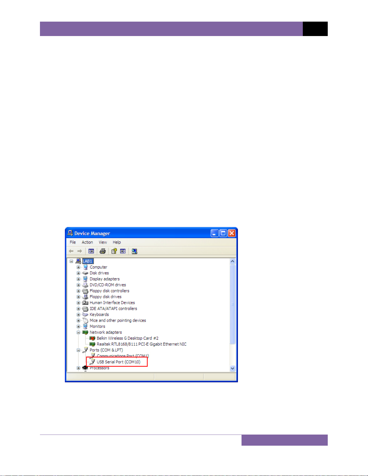
e. Please note that although the unit is connected via USB, it uses an internal serial
interface to communicate with the PC. As such, it will appear in the windows Device
Manager as a USB Serial Port. Open the Device Manager from the Windows Control
Panel and note the COM port number. For example, in the installation shown below, the
CT-3500 S2 is shown as COM10 (USB Serial Port).
10
Page 15
REV 1 CT-3500 S2 USER’S MANUAL
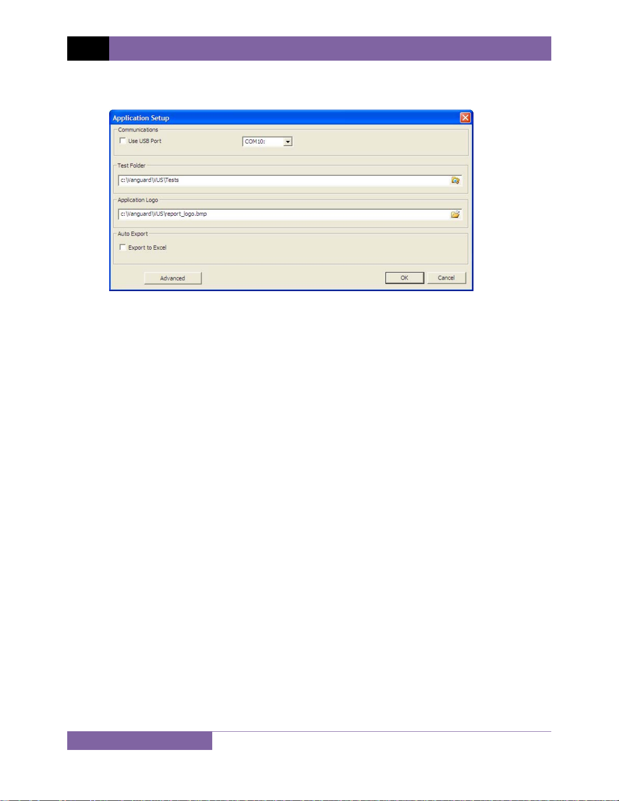
f. Launch the VUS application and then click on the “Settings” icon. The following window
will be displayed:
Make sure that the “Use USB Port” option is UN-checked. Then, from the drop down
menu to the right of the “Use USB Port” checkbox select the COM port that corresponds
to the port that the CT-3500 S2 is connected to. In the above example, the CT-3500 S2 is
connected to COM10. Then click the OK button.
g. You can now use the VUS software to transfer test records from the CT-3500 S2 to the
PC.
11
Page 16

CT-3500 S2 USER’S MANUAL REV 1
3.5 Testing Procedures
3.5.1. Entering Test Record Header Information
You can enter the test record header information before performing tests. The record header
includes identifying information such as the company, station, circuit, manufacturer, etc. Once
the header information has been set, it will apply to all subsequent test records. Follow the
steps below to enter the test header information:
a. Start from the “START-UP” menu:
1. TIME BRKR 05/14/12
2. GET RSLT 08:45:25
3. SETUP
4. DIAGNOSTICS
Press the [3] key (SETUP).
b. The following screen will be displayed:
1. SHOT DESCRIPTION
2. SAVE / RESTORE
3. SET 50/60 HZ
4. SET DATE & TIME
Press the [1] key (SHOT DESCRIPTION).
c. The following screen will be displayed:
COMPANY:
_
↑/↓ TO POSITION
"ENTER" TO ACCEPT
Type the company name using the keypad. Press the [ENTER] key when you are done
typing the company name.
12
Page 17

REV 1 CT-3500 S2 USER’S MANUAL
d. The following screen will be displayed:
STATION:
_
↑/↓ TO POSITION
"ENTER" TO ACCEPT
Type the station name using the keypad and then press the [ENTER] key.
e. The following screen will be displayed:
CIRCUIT:
_
↑/↓ TO POSITION
"ENTER" TO ACCEPT
Type the circuit information using the keypad and then press the [ENTER] key.
f. The following screen will be displayed:
MANUFACTURER:
_
↑/↓ TO POSITION
"ENTER" TO ACCEPT
Type the manufacturer name using the keypad and then press the [ENTER] key.
13
Page 18

g. The following screen will be displayed:
MODEL:
_
↑/↓ TO POSITION
"ENTER" TO ACCEPT
Type the circuit breaker’s model information using the keypad and then press the
[ENTER] key.
h. The following screen will be displayed:
SERIAL NUMBER:
_
↑/↓ TO POSITION
"ENTER" TO ACCEPT
CT-3500 S2 USER’S MANUAL REV 1
Type the circuit breaker’s serial number using the keypad and then press the [ENTER]
key.
i. The following screen will be displayed:
KVA RATING:
_
↑/↓ TO POSITION
"ENTER" TO ACCEPT
Type the circuit breaker’s KVA rating using the keypad and then press the [ENTER] key.
j. The following screen will be displayed:
OPERATOR:
_
↑/↓ TO POSITION
"ENTER" TO ACCEPT
Type the operator’s name using the keypad and then press the
[ENTER] key. All
header information will be saved, and you will be returned to the “START-UP” menu.
14
Page 19

REV 1 CT-3500 S2 USER’S MANUAL
3.5.2. Timing an OPEN Operation
Follow the steps below to time an OPEN operation:
a. Start from the “START-UP” menu:
1. TIME BRKR 05/14/12
2. GET RSLT 08:45:25
3. SETUP
4. DIAGNOSTICS
Press the
[1] key (TIME BRKR).
b. The following screen will be displayed:
TIMING MODE:
1.OPEN 2.CLOSE
3.OPEN-CL 4.CL-OPEN
5. SP OPEN
Press the
[1] key (OPEN).
c. The following screen will be displayed:
TEST: OPEN
OPEN BREAKER NOW...
Manually open the breaker.
d. The following screen will be displayed:
PRINT TEST RESULTS?
1.YES
2.NO
Press the
15
[1] key (YES) to print the test results on the unit’s built-in thermal printer.
Page 20

CT-3500 S2 USER’S MANUAL REV 1
You can also view the test results on the unit’s LCD screen. Please see section
3.6.1.
NOTE
e. The test results will be printed (please see Figure 4) and the following screen will be
displayed:
SAVE THIS SHOT?
1.YES
2.NO
Press the
NOTE
[1] key (YES) to save the test shot.
If a USB Flash drive is connected to the unit’s “USB MEM” port, the following
screen will be displayed:
1.SAVE INTERNALLY
2.SAVE TO THUMB DRIVE
1. SAVE INTERNALLY
Press the [1] key (SAVE INTERNALLY) to save the test shot to the unit’s
internal memory. Continue to step f.
2. SAVE TO THUMB DRIVE
Press the [2] key (SAVE TO THUMB DRIVE) to save the test shot to the
connected USB Flash drive. The test record will be saved and the following
screen will be displayed:
REC_000 SAVED TO
THUMB DRIVE.
Press any key to return to the “START-UP” menu.
16
Page 21

REV 1 CT-3500 S2 USER’S MANUAL
f. The following screen will be displayed:
SHOT NUMBER 18
HAS BEEN SAVED!
Press any key to return to the “START-UP” menu.
17
Figure 4. Sample OPEN Test Results Printout
Page 22

3.5.3. Timing a CLOSE Operation
Follow the steps below to time a CLOSE operation:
a. Start from the “START-UP” menu:
1. TIME BRKR 05/14/12
2. GET RSLT 08:45:25
3. SETUP
4. DIAGNOSTICS
CT-3500 S2 USER’S MANUAL REV 1
Press the
[1] key (TIME BRKR).
b. The following screen will be displayed
TIMING MODE:
1.OPEN 2.CLOSE
3.OPEN-CL 4.CL-OPEN
5. SP OPEN
Press the
[2] key (CLOSE).
c. The following screen will be displayed:
TEST: CLOSE
CLOSE BREAKER NOW...
Manually close the breaker.
d. The following screen will be displayed:
PRINT TEST RESULTS?
1.YES
2.NO
Press the
[1] key (YES) to print the test results on the unit’s built-in thermal printer.
18
Page 23

REV 1 CT-3500 S2 USER’S MANUAL
You can also view the test results on the unit’s LCD screen. Please see section
3.6.1.
NOTE
e. The test results will be printed (please see Figure 5) and the following screen will be
displayed:
SAVE THIS SHOT?
1.YES
2.NO
Press the [1] key (YES) to save the test shot.
If a USB Flash drive is connected to the unit’s “USB MEM” port, the following
screen will be displayed:
NOTE
1.SAVE INTERNALLY
2.SAVE TO THUMB DRIVE
1. SAVE INTERNALLY
Press the [1] key (SAVE INTERNALLY) to save the test shot to the unit’s
internal memory. Continue to step f.
2. SAVE TO THUMB DRIVE
Press the [2] key (SAVE TO THUMB DRIVE) to save the test shot to the
connected USB Flash drive. The test record will be saved and the following
screen will be displayed:
REC_000 SAVED TO
THUMB DRIVE.
Press any key to return to the “START-UP” menu.
19
Page 24

f. The following screen will be displayed:
SHOT NUMBER 19
HAS BEEN SAVED!
Press any key to return to the “START-UP” menu.
CT-3500 S2 USER’S MANUAL REV 1
Figure 5. Sample CLOSE Test Results Printout
20
Page 25

REV 1 CT-3500 S2 USER’S MANUAL
3.5.4. Timing an OPEN-CLOSE Operation
Follow the steps below to time an OPEN-CLOSE operation:
a. Start from the “START-UP” menu:
1. TIME BRKR 05/15/12
2. GET RSLT 09:15:25
3. SETUP
4. DIAGNOSTICS
Press the
[1] key (TIME BRKR).
b. The following screen will be displayed:
TIMING MODE:
1.OPEN 2.CLOSE
3.OPEN-CL 4.CL-OPEN
5. SP OPEN
Press the
[3] key (OPEN-CL).
c. The following screen will be displayed:
TEST: OPEN-CLOSE
OPEN BREAKER NOW...
Manually initiate an OPEN-CLOSE operation on the breaker.
d. The following screen will be displayed:
PRINT TEST RESULTS?
1.YES
2.NO
Press the
21
[1] key (YES) to print the test results on the unit’s built-in thermal printer.
Page 26

CT-3500 S2 USER’S MANUAL REV 1
You can also view the test results on the unit’s LCD screen. Please see section
3.6.1.
NOTE
e. The test results will be printed (please see Figure 6) and the following screen will be
displayed:
SAVE THIS SHOT?
1.YES
2.NO
.
Press the [1] key (YES) to save the test shot.
If a USB Flash drive is connected to the unit’s “USB MEM” port, the following
screen will be displayed:
NOTE
1.SAVE INTERNALLY
2.SAVE TO THUMB DRIVE
1. SAVE INTERNALLY
Press the [1] key (SAVE INTERNALLY) to save the test shot to the unit’s
internal memory. Continue to step f.
2. SAVE TO THUMB DRIVE
Press the [2] key (SAVE TO THUMB DRIVE) to save the test shot to the
connected USB Flash drive. The test record will be saved and the following
screen will be displayed:
REC_000 SAVED TO
THUMB DRIVE.
Press any key to return to the “START-UP” menu.
22
Page 27

REV 1 CT-3500 S2 USER’S MANUAL
f. The following screen will be displayed:
SHOT NUMBER 20
HAS BEEN SAVED!
Press any key to return to the “START-UP” menu.
23
Figure 6. Sample OPEN-CLOSE Test Results Printout
Page 28

3.5.5. Timing a CLOSE-OPEN Operation
Follow the steps below to time a CLOSE-OPEN operation:
a. Start from the “START-UP” menu:
1. TIME BRKR 05/15/12
2. GET RSLT 09:15:25
3. SETUP
4. DIAGNOSTICS
CT-3500 S2 USER’S MANUAL REV 1
Press the
[1] key (TIME BRKR).
b. The following screen will be displayed:
TIMING MODE:
1.OPEN 2.CLOSE
3.OPEN-CL 4.CL-OPEN
5. SP OPEN
Press the
[4] key (CL-OPEN).
c. The following screen will be displayed:
TEST: CLOSE-OPEN
CLOSE BREAKER NOW...
Manually initiate a CLOSE-OPEN operation on the breaker.
d. The following screen will be displayed:
PRINT TEST RESULTS?
1.YES
2.NO
Press the
[1] key (YES) to print the test results on the unit’s built-in thermal printer.
24
Page 29

REV 1 CT-3500 S2 USER’S MANUAL
You can also view the test results on the unit’s LCD screen. Please see section
3.6.1.
NOTE
e. The test results will be printed (please see Figure 7) and the following screen will be
displayed:
SAVE THIS SHOT?
1.YES
2.NO
Press the [1] key (YES) to save the test shot.
If a USB Flash drive is connected to the unit’s “USB MEM” port, the following
screen will be displayed:
NOTE
1.SAVE INTERNALLY
2.SAVE TO THUMB DRIVE
1. SAVE INTERNALLY
Press the [1] key (SAVE INTERNALLY) to save the test shot to the unit’s
internal memory. Continue to step f.
2. SAVE TO THUMB DRIVE
Press the [2] key (SAVE TO THUMB DRIVE) to save the test shot to the
connected USB Flash drive. The test record will be saved and the following
screen will be displayed:
REC_000 SAVED TO
THUMB DRIVE.
Press any key to return to the “START-UP” menu.
25
Page 30

f. The following screen will be displayed:
SHOT NUMBER 21
HAS BEEN SAVED!
Press any key to return to the “START-UP” menu.
CT-3500 S2 USER’S MANUAL REV 1
Figure 7. Sample CLOSE-OPEN Test Results Printout
26
Page 31

REV 1 CT-3500 S2 USER’S MANUAL
3.5.6. Timing a Special OPEN Operation
Some special circuit breakers are designed in such a way that two of the dry-contacts follow the
breaker operation while the third contact operates in the opposite direction. For example,
when an OPEN operation is performed, two of the dry-contacts open while the third contact
closes. The CT-3500 S2 offers a special OPEN test that can be used to time such a breaker.
Follow the steps below to perform a special OPEN operation:
a. Start from the “START-UP” menu:
1. TIME BRKR 05/16/12
2. GET RSLT 09:55:55
3. SETUP
4. DIAGNOSTICS
Press the [1] key (TIME BRKR).
b. The following screen will be displayed:
TIMING MODE:
1.OPEN 2.CLOSE
3.OPEN-CL 4.CL-OPEN
5. SP OPEN
Press the [5] key (SP OPEN).
c. The following screen will be displayed:
TEST: OPEN
OPEN BREAKER NOW...
Manually initiate an OPEN operation on the breaker.
27
Page 32

d. The following screen will be displayed:
PRINT TEST RESULTS?
1.YES
2.NO
CT-3500 S2 USER’S MANUAL REV 1
Press the
[1] key (YES) to print the test results on the unit’s built-in thermal printer.
You can also view the test results on the unit’s LCD screen. Please see section
3.6.1.
NOTE
e. The test results will be printed (please see Figure 8) and the following screen will be
displayed:
SAVE THIS SHOT?
1.YES
2.NO
Press the [1] key (YES) to save the test shot.
If a USB Flash drive is connected to the unit’s “USB MEM” port, the following
screen will be displayed:
NOTE
1.SAVE INTERNALLY
2.SAVE TO THUMB DRIVE
1. SAVE INTERNALLY
Press the [1] key (SAVE INTERNALLY) to save the test shot to the unit’s
internal memory. Continue to step f.
2. SAVE TO THUMB DRIVE
Press the [2] key (SAVE TO THUMB DRIVE) to save the test shot to the
connected USB Flash drive. The test record will be saved and the following
screen will be displayed:
28
Page 33

REV 1 CT-3500 S2 USER’S MANUAL
REC_000 SAVED TO
THUMB DRIVE.
Press any key to return to the “START-UP” menu.
f. The following screen will be displayed
SHOT NUMBER 22
HAS BEEN SAVED!
Press any key to return to the “START-UP” menu.
Figure 8. Sample Special OPEN Test Results Printout
29
Page 34

CT-3500 S2 USER’S MANUAL REV 1
3.6 Working With Test Shots
3.6.1. View ing the Contents of the Working Memory
Whenever a test is performed and the reading is kept, the data is temporarily stored in the CT3500 S2’s working memory. You can view the test reading in the unit’s working memory using
the steps below:
a. Start from the “START-UP” menu:
1. TIME BRKR 05/15/12
2. GET RSLT 09:15:25
3. SETUP
4. DIAGNOSTICS
Press the [2] key (GET RSLT).
b. The following screen will be displayed:
REVIEW TEST
1.DISPLAY TEST DATA
2.PRINT TEST DATA
1. DISPLAY TEST DATA
Press the [1] key (DISPLAY TEST DATA) to display the test results on the unit’s
LCD screen. The following screen will be displayed:
SHOT NUMBER: 2
OPEN SHOT
05/15/12 10:07:29
VANGUARD INSTRUMENTS
Press any key to view the test results. The following screen will be displayed:
OPEN (ms / cycles)
a 329.6ms 19.776CY
B 330.6ms 19.836CY
C 331.6ms 19.896CY
bounce times:
A 0.0ms 0.000CY
B 0.0ms 0.000CY
C 0.0ms 0.000CY
Press any key to return to the “START-UP” menu.
30
Page 35

REV 1 CT-3500 S2 USER’S MANUAL
2. PRINT TEST DATA
Press the [2] key (PRINT TEST DATA) to print the test results on the unit’s built-in
thermal printer. The test results will be printed and you will be returned to the
“START-UP” menu.
31
Page 36

CT-3500 S2 USER’S MANUAL REV 1
3.6.2. Saving Test Results to a Test Shot
After performing a test, the user is presented the option to save the test results to the unit’s
Flash EEPROM or to a USB Flash Drive. If the test results are not saved immediately after
performing a test, they will still remain in the working memory and can be saved later, as long
as a new test has not been performed and the unit has not been turned off. Follow the steps
below to save the test results from the working memory to a test record (the following
procedure can also be used to re-save a restored test record to a new memory location or to a
USB Flash Drive):
a. Perform a test or restore a test record to the working memory (see section 3.6.3 and
3.6.4), and then start from the “START-UP” menu:
1. TIME BRKR 05/16/12
2. GET RSLT 09:55:55
3. SETUP
4. DIAGNOSTICS
Press the [3] key (SETUP).
b. The following screen will be displayed:
1. SHOT DESCRIPTION
2. SAVE / RESTORE
3. SET 50/60 HZ
4. SET DATE & TIME
Press the
[2] key (SAVE / RESTORE)
c. The following screen will be displayed:
1. SAVE SHOT
2. RESTORE SHOT
3. SHOT DIRECTORY
4. ERASE SHOT
5. COPY TO THUMB DRIVE
Option 5 (COPY TO THUMB DRIVE) will be listed only if a USB Flash drive is
connected to the CT-3500 S2.
NOTE
Press the [1] key (SAVE SHOT).
32
Page 37

REV 1 CT-3500 S2 USER’S MANUAL
If a USB Flash drive is connected to the unit, continue to step d.
If a USB Flash drive is NOT connected to the unit, continue to step e.
d. The following screen will be displayed:
1. SAVE INTERNALLY
2. SAVE TO THUMB DRIVE
1. SAVE INTERNALLY
Press the
[1] key (SAVE INTERNALLY) to save the test record to the unit’s Flash
EEPROM. Continue to step e.
2. SAVE TO THUMB DRIVE
Press the
[2] key (SAVE TO THUMB DRIVE) to save the test record to the
connected USB Flash drive. The following screen will be displayed:
REC_001 SAVED TO
THUMB DRIVE.
Press any key to return to the “START-UP” menu.
e. The following screen will be displayed
SHOT NUMBER 23
HAS BEEN SAVED!
Press any key to return to the “START-UP” menu.
33
Page 38

CT-3500 S2 USER’S MANUAL REV 1
3.6.3. Restoring a Test Shot From Flash EEPROM
Use the steps below to restore a test record from the CT-3500 S2’s internal Flash EEPROM to
the working memory:
a. Start from the “START-UP” menu:
1. TIME BRKR 05/16/12
2. GET RSLT 09:55:55
3. SETUP
4. DIAGNOSTICS
Press the [3] key (SETUP).
b. The following screen will be displayed:
1. SHOT DESCRIPTION
2. SAVE / RESTORE
3. SET 50/60 HZ
4. SET DATE & TIME
Press the [2] key (SAVE / RESTORE).
c. The following screen will be displayed:
1. SAVE SHOT
2. RESTORE SHOT
3. SHOT DIRECTORY
4. ERASE SHOT
5. COPY TO THUMB DRIVE
Option 5 (COPY TO THUMB DRIVE) will be listed only if a USB Flash drive is
connected to the unit.
NOTE
Press the [2] key (RESTORE SHOT).
34
Page 39

REV 1 CT-3500 S2 USER’S MANUAL
d. The following screen will be displayed:
RESTORE SHOT
1.ENTER SHOT NUMBER
2.SCROLL TO SELECT
If you have a USB Flash drive inserted in the unit’s “USB MEM” port, the
following screen will be displayed instead of the above screen:
NOTE
1.INTERNAL STORAGE
2.THUMB DRIVE
Press the [1] key (INTERNAL STORAGE).
The following screen will be displayed:
RESTORE SHOT
1.ENTER SHOT NUMBER
2.SCROLL TO SELECT
Continue with the steps below.
1. ENTER SHOT NUMBER
Press the
[1] key (ENTER SHOT NUMBER) if you know the record number that
you would like to restore.
1.1. The following screen will be displayed:
RESTORE SHOT NUM:
35
Type the shot number using the keypad and then press the
[ENTER] key.
Page 40

CT-3500 S2 USER’S MANUAL REV 1
1.2. The following screen will be displayed:
SHOT 001 RESTORED!
The test shot will be restored to the unit’s working memory. You can then
view or print the test shot information using the instructions in section
3.6.1.
Press any key to return to the “START-UP” menu.
2. SCROLL TO SELECT
Press the [2] key (SCROLL TO SELECT) to scroll through a directory of stored test
shots.
2.1. The following screen will be displayed:
SHOT DIRECTORY
"UP" TO SCROLL FWD
"DWN" TO SCROLL RVS
"ENTER" TO SELECT
Press the [∧] button or the [∨] key to display the next or previous test
record, respectively.
The basic test record information will be displayed as shown:
SHOT NUMBER: 30
OPEN SHOT
05/16/12 09:14:06
VANGUARD INSTRUMENTS
When you have located the test record that you would like to restore,
press the [ENTER] key. The test shot will be restored to the unit’s
working memory. You can then view or print the test shot information
using the instructions in section 3.6.1.
Press any key to return to the “START-UP” menu.
36
Page 41

REV 1 CT-3500 S2 USER’S MANUAL
3.6.4. Restoring a Test Shot From a USB Flash Drive
Use the steps below to restore a test record from a USB Flash drive to the CT-3500 S2’s working
memory:
a. Make sure the USB Flash drive containing the test record(s) is inserted in the CT-3500
S2’s USB Flash drive port (“USB MEM” port). Then start from the “START-UP” menu:
1. TIME BRKR 05/16/12
2. GET RSLT 09:55:55
3. SETUP
4. DIAGNOSTICS
Press the [3] key (SETUP).
b. The following screen will be displayed:
1. SHOT DESCRIPTION
2. SAVE / RESTORE
3. SET 50/60 HZ
4. SET DATE & TIME
Press the [2] key (SAVE / RESTORE)
c. The following screen will be displayed:
1. SAVE SHOT
2. RESTORE SHOT
3. SHOT DIRECTORY
4. ERASE SHOT
5. COPY TO THUMB DRIVE
Press the
[2] key (RESTORE SHOT).
37
Page 42

d. The following screen will be displayed:
1.INTERNAL STORAGE
2.THUMB DRIVE
Press the [2] key (THUMB DRIVE).
e. The following screen will be displayed:
RESTORE THUMB DRIVE
REC_
CT-3500 S2 USER’S MANUAL REV 1
Type the record number that you would like to restore using the alpha-numeric keypad
and then press the [ENTER] key.
f. The test record will be restored to the unit’s working memory and the following screen
will be displayed:
REC_001 restored!
PRINT RECORD?
1.YES
2.NO
Press the
[1] key (YES) if you would like to print the test record, or press the [2] key
(NO) if you do not want to print the test record. The test record will be restored to the
unit’s working memory, and you will be returned to the “START-UP” menu.
38
Page 43

REV 1 CT-3500 S2 USER’S MANUAL
3.6.5. Copying Test Records to a USB Flash Drive
Use the steps below to copy one or all test records from the unit’s Flash EEPROM to a
connected USB Flash drive:
a. Make sure a USB Flash drive is connected to the unit’s “USB MEM” port, and then start
from the “START-UP” menu:
1. TIME BRKR 05/16/12
2. GET RSLT 09:55:55
3. SETUP
4. DIAGNOSTICS
Press the [3] key (SETUP).
b. The following screen will be displayed:
1. SHOT DESCRIPTION
2. SAVE / RESTORE
3. SET 50/60 HZ
4. SET DATE & TIME
Press the [2] key (SAVE / RESTORE).
c. The following screen will be displayed:
1. SAVE SHOT
2. RESTORE SHOT
3. SHOT DIRECTORY
4. ERASE SHOT
5. COPY TO THUMB DRIVE
Press the
[5] key (COPY TO THUMB DRIVE).
39
Page 44

d. The following screen will be displayed:
COPY REC TO THUMB DRV
1.COPY SINGLE RECORD
2.COPY ALL RECORDS
1. COPY SINGLE RECORD
Press the [1] key (COPY SINGLE RECORD) to copy a single test record from the
unit’s Flash EEPROM to the connected USB Flash drive. The following screen will
be displayed:
ENTER RECORD NUMBER
TO COPY TO FLASH DRV
NUMBER:
CT-3500 S2 USER’S MANUAL REV 1
Type the record number using the alpha-numeric keypad and then press the
[ENTER] key. The test record will be copied to the USB Flash drive and the
following screen will be displayed:
REC_013 SAVED TO
THUMB DRIVE
Press any key to return to the “START-UP” menu.
40
Page 45

REV 1 CT-3500 S2 USER’S MANUAL
2. COPY ALL RECORDS
Press the [2] key (COPY ALL RECORDS) to copy all test records from the unit’s
Flash EEPROM to the connected USB Flash drive. All test records will be copied
from the unit to the connected USB Flash drive. The following screen will be
displayed when the process is finished:
ALL RECORDS HAVE BEEN
TRANSFERRED TO THUMB
DRIVE!
Press any key to return to the “START-UP” menu.
41
Page 46

CT-3500 S2 USER’S MANUAL REV 1
3.6.6. Printing the Test Record Directory
Use the steps below to print a directory of the test records stored in the CT-3500 S2’s Flash
EEPROM memory or on a connected USB Flash drive:
a. Start from the “START-UP” menu:
1. TIME BRKR 05/16/12
2. GET RSLT 09:55:55
3. SETUP
4. DIAGNOSTICS
Press the [3] key (SETUP).
b. The following screen will be displayed:
1. SHOT DESCRIPTION
2. SAVE / RESTORE
3. SET 50/60 HZ
4. SET DATE & TIME
Press the [2] key (SAVE / RESTORE).
c. The following screen will be displayed:
1. SAVE SHOT
2. RESTORE SHOT
3. SHOT DIRECTORY
4. ERASE SHOT
5. COPY TO THUMB DRIVE
Option 5 (COPY TO THUMB DRIVE) is listed only if a USB Flash drive is
connected to the unit.
NOTE
Press the [3] key (SHOT DIRECTORY).
If a USB Flash drive is not connected to the unit, a directory of the shots stored in the
unit’s Flash EEPROM will be printed. You will be returned to the “START-UP” menu
when printing is finished.
42
Page 47

REV 1 CT-3500 S2 USER’S MANUAL
If a USB Flash drive is connected to the unit, the following screen will be displayed:
1. INTERNAL DIRECTORY
2. THUMB DRIVE DIR
1. INTERNAL DIRECTORY
Press the [1] key (INTERNAL DIRECTORY) to print a directory of test shots stored
in the unit’s Flash EEPROM. The directory will be printed on the unit’s built-in
thermal printer, and you will be returned to the “START-UP” menu when printing
is finished.
2. THUMB DRIVE DIR
Press the [2] key (THUMB DRIVE DIR) to print a directory of test shots stored on
the connected USB Flash drive. The unit will search the thumb drive for test
records and then a directory will be printed on the unit’s thermal printer. You
will be returned to the “START-UP” menu when printing is finished.
43
Page 48

CT-3500 S2 USER’S MANUAL REV 1
3.6.7. Erasing Test Records from the Flash EEPROM
Follow the steps below to erase test records from the Flash EEPROM
a. Start from the “START-UP” menu:
1. TIME BRKR 05/16/12
2. GET RSLT 09:55:55
3. SETUP
4. DIAGNOSTICS
Press the
[3] key (SETUP).
b. The following screen will be displayed:
1. SHOT DESCRIPTION
2. SAVE / RESTORE
3. SET 50/60 HZ
4. SET DATE & TIME
Press the
[2] key (SAVE / RESTORE).
c. The following screen will be displayed:
1. SAVE SHOT
2. RESTORE SHOT
3. SHOT DIRECTORY
4. ERASE SHOT
5. COPY TO THUMB DRIVE
Press the
[4] key (ERASE SHOT).
d. The following screen will be displayed:
ERASE SHOTS
1.ERASE SINGLE SHOT
2.ERASE ALL SHOTS
1. ERASE SINGLE SHOT
Press the
[1] key (ERASE SINGLE SHOT) to erase a single test record from the unit’s
internal Flash EEPROM. The following screen will be displayed:
44
Page 49

REV 1 CT-3500 S2 USER’S MANUAL
ERASE SHOT NUM:
Type the record number that you would like to erase using the keypad and then
press the [ENTER] key. If you do not know the test record number, you can first
print the test record directory using the instructions in section 3.6.6.
The following screen will be displayed while the record is being erased:
ERASing SHOT
PLEASE WAIT...
The following screen will be displayed when the test record has been completely
erased:
SHOT 001 ERASED!
Press any key to return to the “START-UP” menu.
45
Page 50

CT-3500 S2 USER’S MANUAL REV 1
2. ERASE ALL SHOTS
Press the [2] key (ERASE ALL SHOTS) to erase all the test records from the unit’s
internal Flash EEPROM. The following warning screen will be displayed:
ERASE ALL SHOTS!
ARE YOU SURE?
"ENTER" To CONTINUE.
You can press the [STOP] key to cancel the process and return to the “START-UP”
menu.
Press the
[ENTER] key to proceed with deleting all the test records from the unit’s
Flash EEPROM. The following screen will be displayed during the erasure process:
ERASing ALL SHOTS
The following screen will be displayed when all test records have been completely
erased:
ALL SHOTS ERASED
Press any key to return to the “START-UP” menu.
46
Page 51

REV 1 CT-3500 S2 USER’S MANUAL
3.7 Performing Cable Diagnostics
The CT-3500 S2 can quickly check the test leads and breaker contacts for continuity at each of
the three phase contacts. Once all connections are made, use the steps below to check your
connections:
a. Start from the “START-UP” menu:
1. TIME BRKR 05/16/12
2. GET RSLT 09:55:55
3. SETUP
4. DIAGNOSTICS
Press the [4] key (DIAGNOSTICS).
b. The following screen will be displayed:
PRESS "ENTER" TO
START CABLE TEST
Open the breaker and then press the [ENTER] key.
c. The following screen will be displayed:
CABLE TEST
CH A CH B CH C
OPEN OPEN OPEN
(ANY KEY TO EXIT)
If the proper connections were made, “OPEN” should be displayed for all channels. You
can now close the breaker. “CLOSED” should be displayed for all channels.
Press any key to return to the “START-UP” menu.
47
Page 52

CT-3500 S2 USER’S MANUAL REV 1
4.0 Getting the Latest Firmware, Software, and Manuals
The latest firmware, software, and user’s manuals can be downloaded from the Vanguard
Instruments Company’s web site at http://www.vanguard-instruments.com. In order to
download these items from our site, you will first need to sign up for a FREE user account on
our site. Also, your account must be approved before it can be used to download firmware,
software, and user’s manuals. Follow the steps below to sign up for an account and download
the latest firmware, software and user’s manuals:
a. Visit our site at http://www.vanguard-instruments.com
b. On the left hand side of the page, click on the “Create new account” link:
c. You will be presented with a sign-up form. Please complete all the required fields on the
form and click on the “Create new account” button at the bottom of the page.
d. Once your account has been created, it will be reviewed by our staff and usually
approved within the hour during regular business hours.
.
e. Once you have received the account approval email, visit our site again at
http://www.vanguard-instruments.com
and password.
f. Click on the “Downloads” link at the top of the page:
g. The “Downloads” page will be displayed listing all Vanguard products along with the
related firmware, software, and user’s manuals. Click on any of these items to download
them.
and login to your account using your username
48
Page 53

1520 S. Hellman Ave • Ontario, CA 91761 • USA
Phone: 909-923-9390 • Fax: 909-923-9391
www.vanguard-instruments.com
Copyright © 2012 by Vanguard Instruments Company, Inc.
CT-3500 S2 User’s Manual • Revision 1.0 • July, 2012 • TA
 Loading...