

Page 1
ATRT-03 S2, ATRT-03A S2, and ATRT-03B S2
THREE-PHASE TRANSFORMER TURNS-RATIO METERS
USER’S MANUAL
Vanguard Instruments Company, Inc.
1520 S. Hellman Ave.
Ontario, California 91761, USA
TEL: (909) 923-9390
FAX: (909) 923-9391
February 2014
Revision 2
Page 2

ATRT-03 S2, ATRT-03A S2, AND ATRT-03B S2 USER’S MANUAL REV 2
SAFETY SUMMARY
This manual applies to the ATRT-03 S2, ATRT-03A S2, and ATRT-3B S2 current transformer
turns-ratio meters. The operating procedures are virtually the same for all three models, and
any differences are clearly described where applicable.
FOLLOW EXACT OPERATING PROCEDURES
Any deviation from procedures described in this User’s Manual may create one or more safety
hazards, damage the ATRT-03/03A/03B S2, damage the test transformer, or cause errors in the
test results. Vanguard Instruments Company, Inc. assumes no liability for unsafe or improper
use of the ATRT-03/03A/03B S2.
SAFETY WARNINGS AND CAUTIONS
The ATRT-03/03A/03B S2 shall be used only by trained operators. All transformers under test
shall be off-line and fully isolated. Always ground the ATRT-03/03A/03B S2 to a substation
ground before connecting the test cables to a transformer. Do not perform test procedures or
service unless another person is also present who is capable of rendering aid and resuscitation.
DO NOT MODIFY TEST EQUIPMENT
To avoid the risk of introducing additional or unknown hazards, do not install substitute parts or
perform any unauthorized modification to any ATRT-03/03A/03B S2 test unit. To ensure that all
designed safety features are maintained, it is highly recommended that repairs be performed
only by Vanguard Instruments Company factory personnel or by an authorized repair service
provider. Unauthorized modifications can cause safety hazards and will void the manufacturer’s
warranty.
WARNING
Do not remove test leads during a test. Failure to heed this warning can result in electrical
shock to personnel and damage to the equipment.
i
Page 3

REV 2 ATRT-03 S2, ATRT-03A S2, AND ATRT-03B S2 USER’S MANUAL
TABLE OF CONTENTS
CONVENTIONS USED IN THIS DOCUMENT ..................................................................................... 1
1.0 INTRODUCTION .................................................................................................................. .. 2
1.1 General Description and Features ................................................................................... 2
1.2 Technical Specifications ................................................................................................... 4
1.2.1. ATRT-03 S2 Technical Specifications ........................................................................ 4
1.2.2. ATRT-03A S2 Technical Specifications ...................................................................... 5
1.2.3. ATRT-03B S2 Technical Specifications ...................................................................... 6
1.3 Controls and Indicators .................................................................................................... 7
2.0 PRE-TEST SETUP ................................................................................................................. 13
2.1 Operating Voltages ........................................................................................................ 13
2.2 LCD Screen Contrast Control .......................................................................................... 13
2.3 Printer Paper Control ..................................................................................................... 13
2.4 Printer Paper .................................................................................................................. 13
2.5 Replacing the Load Tap Changer Controller Fuses ........................................................ 14
3.0 OPERATING PROCEDURES ................................................................................................. 16
3.1 Connection Diagrams ..................................................................................................... 16
3.1.1. Typical Front Panel Connections .................................................................................... 16
3.1.2. Typical Connections to a Load Tap Changer (LTC) ......................................................... 17
3.1.3. Typical Connections to a Delta-Wye Transformer ......................................................... 18
3.2 Setting the Test Voltage ................................................................................................. 26
3.3 Setting the Date and Time ............................................................................................. 28
3.4 Performing Tests ............................................................................................................ 29
3.4.1. Entering Test Record Header Information ............................................................. 29
3.4.2. Testing a Single Phase Transformer ....................................................................... 33
3.4.3. Testing a Dyn1 (12,000 V/208 V) Transformer ....................................................... 42
3.4.4. Testing a Three Phase Transformer Using Auto Detect Mode .............................. 52
3.5 Working With Test Records ........................................................................................... 59
3.5.1. Saving Test Results to a Test Record ...................................................................... 59
3.5.2. Restoring a Test Record From Flash EEPROM ........................................................ 62
3.5.3. Restoring a Test Record From a USB Flash Drive ................................................... 67
3.5.4. Copying Test Records to a USB Flash Drive ............................................................ 71
3.5.5. Printing or Displaying a Test Record ...................................................................... 74
3.5.6. Printing a Test Record Directory (ATRT-03 S2 and ATRT-03A S2 Only) .................. 77
3.5.7. Viewing a Test Record Directory on the LCD Screen (ATRT-03B S2 Only) ............. 80
3.5.8. Erasing Test Records from the Flash EEPROM ....................................................... 82
3.5.9. Erasing Test Records from a USB Flash Drive ......................................................... 86
3.6 Working With Test Plans ................................................................................................ 89
3.6.1. Performing a Test Using a Transformer Test Plan .................................................. 89
3.6.2. Unloading a Test Plan From the Working Memory ................................................ 96
3.6.3. Printing a Test Plan Directory (ATRT-03 S2 and ATRT-03A S2 Only) ...................... 97
3.6.4. Viewing a Test Plan Directory on the LCD Screen (ATRT-03B S2 Only) .................. 99
3.6.5. Printing a Test Plan (ATRT-03 S2 and ATRT-03A S2 Only) .................................... 101
ii
Page 4

ATRT-03 S2, ATRT-03A S2, AND ATRT-03B S2 USER’S MANUAL REV 2
3.6.6. Saving a Test Plan ................................................................................................. 104
3.6.7. Copying a Test Plan to a USB Flash Drive ............................................................. 106
3.6.8. Erasing Test Plans ................................................................................................. 108
4.0 DIAGNOSTICS, VERIFICATION, AND TROUBLESHOOTING ............................................... 112
4.1 Performing an H and X Cable Diagnostic Test ............................................................. 112
4.2 Performing a Verification Test ..................................................................................... 114
5.0 UPGRADING FIRMWARE .................................................................................................. 116
APPENDIX A – TRANSFORMER VECTOR GROUP CODES ............................................................. 119
APPENDIX B – Common ANSI Transformer Descriptions ........................................................... 120
APPENDIX C – CEI/IEC 60076-1 Transformer Descriptions ......................................................... 128
APPENDIX D – Australian Std.2374 Transformer Descriptions ................................................... 135
iii
Page 5

REV 2 ATRT-03 S2, ATRT-03A S2, AND ATRT-03B S2 USER’S MANUAL
LIST OF TABLES
Table 1. ATRT-03 S2 Technical Specifications ................................................................................. 4
Table 2. ATRT-03A S2 Technical Specifications ............................................................................... 5
Table 3. ATRT-03B S2 Technical Specifications ............................................................................... 6
Table 4. Functional Descriptions of ATRT-03 S2 Controls and Indicators ...................................... 8
Table 5. Functional Descriptions of ATRT-03A S2 Controls and Indicators .................................. 10
Table 6. Functional Descriptions of ATRT-03B S2 Controls and Indicators .................................. 12
Table 7. Descriptions of Single Phase Test Results Elements (Column Format) .......................... 39
Table 8. Descriptions of Single Phase Test Results Elements (Detailed Format) ......................... 41
Table 9. Descriptions of Dyn1 Test Results Elements (Column Format) ...................................... 49
Table 10. Descriptions of Dyn1 Test Results Elements (Detailed Format) ................................... 51
LIST OF FIGURES
Figure 1. ATRT-03 S2 Controls and Indicators ................................................................................ 7
Figure 2. ATRT-03A S2 Controls and Indicators .............................................................................. 9
Figure 3. ATRT-03B S2 Controls and Indicators ............................................................................ 11
Figure 4. Typical Front Panel Cable Connections .......................................................................... 16
Figure 5. Typical Connections to a Load Tap Changer (LTC) ......................................................... 17
Figure 6. Typical H & X Cable Connections to a Delta-Wye Transformer ..................................... 18
Figure 7. Typical Connections to a Single Phase Transformer ...................................................... 19
Figure 8. Typical Connections to a Single Phase Auto Transformer ............................................. 19
Figure 9. Typical Connections to a Type A Voltage Regulator ...................................................... 20
Figure 10. Typical Connections to a Type B Voltage Regulator .................................................... 20
Figure 11. Typical Connections to a Donut Type (un-mounted) Current Transformer (CT) ......... 21
Figure 12. Typical Connections to a Multi-Tap Current Transformer ........................................... 22
Figure 13. Typical Connections to a Bushing Mount CT on a Single Phase Transformer ............. 23
Figure 14. Typical Connections to Bushing Mount CT's on Delta Transformer ............................ 24
Figure 15. Typical Connections to Bushing Mount CT's on Wye Transformer ............................. 25
Figure 17. Single Phase Test Results Printout - Column Format .................................................. 39
Figure 18. Single Phase Test Results Printout - Detailed Format ................................................. 40
Figure 19. Dyn1 Test Results Printout - Column Format .............................................................. 48
Figure 20. Dyn1 Test Results Printout - Detailed Format ............................................................. 50
Figure 21. Typical USB Flash Drive (Thumb Drive) Test Record Directory Printout ..................... 79
Figure 22. Typical Internal Flash EEPROM Test Record Directory Printout .................................. 79
Figure 23. Test Plan Test Results Printout .................................................................................... 95
Figure 24. Sample Printout of a Test Plan from a USB Flash Drive ............................................. 102
Figure 25. Sample Printout of a Test Plan from Internal Memory ............................................. 103
iv
Page 6
ATRT-03 S2, ATRT-03A S2, AND ATRT-03B S2 USER’S MANUAL REV 2
CONVENTIONS USED IN THIS DOCUMENT
This document uses the following conventions:
•
The general term “ATRT” is used in this manual to refer to any of the ATRT-03 S2 models
(ATRT-03 S2, ATRT-03A S2, and ATRT-3B S2).
A key, switch, or knob on the ATRT is indicated as
•
Menu names are referenced as “MENU NAME”
•
[KEY], [SWITCH], [KNOB].
• ATRT LCD screen output is shown as:
1. OPTION 1
2. OPTION 2
3. OPTION 3
4. OPTION 4
5. OPTION 5
• When instructions are provided, the menu item that should be selected is outlined with a
rectangle as shown below (option 3 should be selected):
1. OPTION 1
2. OPTION 2
3. OPTION 3
4. OPTION 4
5. OPTION 5
• Warning messages are indicated as:
Warning message
WARNING
• Important notes are indicated as:
Note details
NOTE
1
Page 7

REV 2 ATRT-03 S2, ATRT-03A S2, AND ATRT-03B S2 USER’S MANUAL
1.0 INTRODUCTION
1.1 General Description and Features
The ATRT-03 S2 line is Vanguard’s third generation family of microprocessor-based, automatic,
three phase, transformer turns-ratio testers. The ATRT-03 S2 line consists of the following three
models:
• The ATRT-03 S2 is a line-powered, 100-240 Vac, 50/60 Hz turns-ratio tester featuring a
built-in thermal printer.
• The ATRT-03A S2 can be powered either by an internal rechargeable lead acid battery,
by 100-240 Vac, or by a 12 Vdc external source. The internal battery provides 3 hours of
operational time. The ATRT-03A S2 also features a built-in thermal printer.
• The ATRT-03B S2 is a line-powered, 100-240 Vac, 50/60 Hz turns-ratio tester without a
built-in thermal printer.
The general term “ATRT-03 S2” or “ATRT” is used in this manual to refer to any of the ATRT-03
S2 models. Any differences are clearly described where applicable.
The ATRT-03 S2 determines the transformer turns-ratio using the IEEE C57.12.90 measurement
method. The ATRT-03 S2 outputs an excitation test voltage to the transformer’s primary
windings. The induced secondary voltage is sensed and the transformer turns-ratio is
calculated. The unit can measure turns-ratios from 0.8 to 15,000. The transformer turns-ratio,
excitation current, and phase-angle readings are displayed on the large back-lit LCD. The built-in
transformer type detection feature allows the ATRT-03 S2 to detect and test 130 transformer
types defined by ANSI, CEI/IEC and Australian standards.
The ATRT-03 S2 can be used as a stand-alone unit or can be computer-controlled. It can be
operated locally using its alpha-numeric keypad and rotary switch. Information is displayed on a
back-lit LCD screen (64 x 128 dot graphic) that is viewable in both bright sunlight and low-light
levels. Test reports can be printed in the field on the unit’s built-in 4.5-inch wide thermal
printer (ATRT-03 S2 and ATRT-03A S2 only). The ATRT-03 S2 can store up to 112 test records
and 128 test plans in Flash EEPROM. Test records or test plans can be stored or transferred to
and from a PC via the available interfaces (RS-232C port, USB port, USB Flash drive port).
Transformer Test Voltage
To prevent an accidental wrong test-lead hook-up (e.g., when the operator reverses H and X
leads), the ATRT-03 S2 outputs a low-level test voltage to verify the hook-up condition before
applying the full test voltage to the transformer. Three test voltages (8 Vac, 40 Vac, 100 Vac)
allow the ATRT-03 S2 to test CT’s and PT’s, as well as power transformers.
Auto-Detect Transformer Configuration
The ATRT-03 S2 can automatically detect 130 specific vector groups for different transformer
types defined by ANSI, CEI/IEC, and Australian standards.
2
Page 8

ATRT-03 S2, ATRT-03A S2, AND ATRT-03B S2 USER’S MANUAL REV 2
User Interface
The ATRT-03 S2 features a back-lit LCD screen (64 x 128 dot graphic) that is viewable in both
bright sunlight and low-light levels. The test results screen displays the transformer turns-ratio,
excitation current, phase angle, and percentage error. The unit is controlled via a rugged, 16key, membrane keypad and a digital rotary switch.
Transformer Test Plans
The ATRT-03 S2 can store up to 128 transformer test plans in its Flash EEPROM. A test plan is
comprised of the transformer nameplate voltages for each tap setting. The calculated turnsratio based on the nameplate voltages is compared with the measured turns-ratio. By recalling
a test plan, a transformer can be quickly tested and turns-ratio Pass/Fail reports can be
reviewed. Test plans can be created with the PC software and can be transferred to the ATRT03 S2 via the available interfaces (RS-232C port, USB port, USB Flash drive port).
Internal Test Record Storage
Up to 112 test records can be stored in the ATRT-03 S2’s Flash EEPROM memory. Each test
record may contain up to 33 turns-ratio, excitation current, phase angle and name plate voltage
readings. Test records can be recalled locally or transferred to a PC via the available interfaces
(RS-232C port, USB port, USB Flash drive port).
USB Flash Drive Interface
A built-in USB Flash drive interface provides a convenient method for transferring test plans
and test records to or from a USB Flash drive. The user can store up to 999 transformer test
plans on a USB Flash drive. Test plans can be transferred from a PC to a USB Flash drive, and
then a specific test plan on the USB Flash drive can be transferred to the ATRT-03 S2’s internal
Flash memory. Up to 999 test records from the field can be stored on a USB Flash drive. Test
records stored in the ATRT-03 S2’s internal memory can also be transferred to a USB Flash
drive. The supplied PC software can then be used to view the test records stored on the USB
Flash drive.
Computer Interface
In computer-controlled mode, the unit can be controlled via the RS-232C or USB port using the
supplied PC software (Transformer Turns-Ratio Analyzer application provided with each ATRT03 S2). This Windows® XP/Vista-based software can be used to run a test and to store test
results on a PC. Test results can also be exported to Microsoft® Excel.
Transformer Load Tap Changer Control
Transformer tap positions can be changed remotely using the unit’s built-in transformer load
tap changer. This remote-controlled tap changer feature eliminates the need to manually
change a transformer’s step-up and step-down taps.
Built-in Thermal Printer (ATRT-03 S2 and ATRT-03A S2 only)
The ATRT-03 S2 and ATRT-03A S2 feature a built-in 4.5-inch wide thermal printer that can print
test results. The printer and paper dispenser are mounted under the front panel for protection.
3
Page 9

REV 2 ATRT-03 S2, ATRT-03A S2, AND ATRT-03B S2 USER’S MANUAL
®
1.2 Technical Specifications
1.2.1. ATRT-03 S2 Technical Specifications
Table 1. ATRT-03 S2 Technical Specifications
TYPE Portable, lightweight, automatic, 3-phase transformer turns-ratio meter
PHYSICAL SPECIFICATIONS 18”W x 7”H x 15”D (45.7 cm x 17.8 cm x 38.1 cm); Weight: 20 lbs (9.0 kg)
OPERATING VOLTAGE 100 – 240 Vac, 50/60 Hz
MEASUREMENT METHOD ANSI/IEEE C57.12.90
TURNS-RATIO MEASURING
RANGE
TURNS-RATIO ACCURACY 0.8 – 1,999: ±0.1%, 2,000 – 3,999: ±0.25%. 4,000 – 15,000: ±1% @ 8 Vac
TEST VOLTAGES 8 Vac @ 1Amp, 40 Vac @ 0.2 Amp, 100 Vac @ 0.1 Amp
EXCITATION CURRENT
READING RANGE
PHASE-ANGLE
MEASUREMENT
DISPLAY Back-lit LCD screen (64 x 128 dot graphic display); Viewable in bright
PRINTER Built-in 4.5-inch wide thermal printer
COMPUTER INTERFACES One RS-232C port, One USB port
EXTERNAL DATA STORAGE One USB Flash drive interface port; Up to 999 transformer test records can
PC SOFTWARE Windows
INTERNAL TEST RECORD
STORAGE
INTERNAL TEST PLAN
STORAGE
LOAD TAP CHANGER
CONTACT
SAFETY Designed to meet UL 61010A-1 and CAN/CSA C22.2 No. 1010.1-92
ENVIRONMENT Operating: -10˚ to 50˚ C (15˚ to +122˚ F); Storage: -30˚ C to 70˚ C (-22˚ to
HUMIDITY (MAX) 90% RH @ 40˚ C (104˚ F) non-condensing
ALTITUDE (MAX) 2000m (6562 ft) to fully safety specifications
CABLES One 15-foot Single-phase set, One 15-foot 3-phase set, One 25-foot
WARRANTY One year on parts and labor
0.8 – 15,000
0.8 – 1,999: ±0.1%, 2,000 – 3,999: ±0.20%. 4,000 – 15,000: ±1% @ 40 Vac
0.8 – 1,999: ±0.1%, 2,000 – 3,999: ±0.15%. 4,000 – 15,000: ±1% @ 100 Vac
0 – 2 Amperes; Accuracy: ±0.1 mA, ±2% of reading (±1 mA)
0 – 360 Degrees; Accuracy: ±0.2 degree (±1 digit)
sunlight and low-light levels
be stored on a USB Flash drive (not included).
XP/Vista-based Transformer Turns-Ratio Analyzer application is
included with purchase price
Can store 112 transformer test records internally. Each record holds the test
record header and up to 33 readings per phase. The readings include turns
ratio readings, excitation current readings, and nameplate voltages.
Can store 128 transformer test plans internally. Test plans can be transferred
to the unit from the PC via the RS-232C/USB port or via the USB Flash drive
interface
240 Vac, 2 Amps
standards
+158˚ F)
extension set, One safety ground, One USB, One RS-232C, One LTC cable,
cable bag
The above specifications are valid at nominal operating voltage and at a
temperature of 25°C (77°F). Specifications may change without prior notice.
NOTE
4
Page 10

ATRT-03 S2, ATRT-03A S2, AND ATRT-03B S2 USER’S MANUAL REV 2
®
1.2.2. ATRT-03A S2 Technical Specifications
Table 2. ATRT-03A S2 Technical Specifications
TYPE Portable, lightweight, automatic, 3-phase transformer turns-ratio meter
PHYSICAL SPECIFICATIONS 20”W x 7.5”H x 15.5”D (50 cm x 19 cm x 39.6 cm); Weight: 27 lbs (12 kg)
OPERATING VOLTAGE 100 – 240 Vac, 50/60 Hz
BATTERIES Two lead acid batteries (12V, 2 AH) provide up to 3 hours of operation
MEASUREMENT METHOD ANSI/IEEE C57.12.90
TURNS-RATIO MEASURING
RANGE
TURNS-RATIO ACCURACY 0.8 – 1,999: ±0.1%, 2,000 – 3,999: ±0.25%. 4,000 – 15,000: ±1% @ 8 Vac
TEST VOLTAGES 8 Vac @ 350 mA, 40 Vac @ 70 mA, 100 Vac @ 20 mA
EXCITATION CURRENT
READING RANGE
PHASE-ANGLE
MEASUREMENT
DISPLAY Back-lit LCD screen (64 x 128 dot graphic display); Viewable in bright
PRINTER Built-in 4.5-inch wide thermal printer
COMPUTER INTERFACES One RS-232C port, One USB port
EXTERNAL DATA STORAGE One USB Flash drive interface port; Up to 999 transformer test records can
PC SOFTWARE Windows
INTERNAL TEST RECORD
STORAGE
INTERNAL TEST PLAN
STORAGE
LOAD TAP CHANGER
CONTACT
SAFETY Designed to meet UL 61010A-1 and CAN/CSA C22.2 No. 1010.1-92
ENVIRONMENT Operating: -10˚ to 50˚ C (15˚ to +122˚ F); Storage: -30˚ C to 70˚ C (-22˚ to
HUMIDITY (MAX) 90% RH @ 40˚ C (104˚ F) non-condensing
ALTITUDE (MAX) 2000m (6562 ft) to fully safety specifications
CABLES One 15-foot single-phase set, One 15-foot 3-phase set, one 25-foot
WARRANTY One year on parts and labor
0.8 – 15,000
0.8 – 1,999: ±0.1%, 2,000 – 3,999: ±0.20%. 4,000 – 15,000: ±1% @ 40 Vac
0.8 – 1,999: ±0.1%, 2,000 – 3,999: ±0.15%. 4,000 – 15,000: ±1% @ 100 Vac
0 – 2 Amperes; Accuracy: ±0.1 mA, ±2% of reading (±1 mA)
0 – 360 degrees; Accuracy: ±0.2 degree ( ±1 digit)
sunlight and low-light levels
be stored on a USB Flash drive (not included).
XP/Vista-based Transformer Turns-Ratio Analyzer application is
included with purchase price
Can store 112 transformer test records internally. Each record holds the test
record header and up to 33 readings per phase. The readings include turns
ratio readings, excitation current readings, and nameplate voltages.
The unit can store 128 transformer test plans. Test plans can be transferred
to the unit from the PC via the RS-232C/USB port or via the USB Flash drive
interface
240 Vac, 1 Amp
standards
+158˚ F)
extension set, One safety ground, One USB, One RS-232, One LTC cable,
cable bag
The above specifications are valid at nominal operating voltage and at a
temperature of 25°C (77°F). Specifications may change without prior notice.
NOTE
5
Page 11

REV 2 ATRT-03 S2, ATRT-03A S2, AND ATRT-03B S2 USER’S MANUAL
®
1.2.3. ATRT-03B S2 Technical Specifications
Table 3. ATRT-03B S2 Technical Specifications
TYPE Portable, lightweight, automatic, 3-phase transformer turns-ratio meter
PHYSICAL SPECIFICATIONS 18”W x 7”H x 15”D (45.7 cm x 17.8 cm x 38.1 cm ); Weight: 20 lbs (9.0 kg)
OPERATING VOLTAGE 100 – 240 Vac, 50/60 Hz
MEASUREMENT METHOD ANSI/IEEE C57.12.90
TURNS-RATIO MEASURING
RANGE
TURNS-RATIO ACCURACY 0.8 – 1,999: ±0.1%, 2,000 – 3,999: ±0.25%. 4,000 – 15,000: ±1% @ 8 Vac
TEST VOLTAGES 8 Vac @ 1Amp, 40 Vac @ 0.2 Amp, 100 Vac @ 0.1 Amp
EXCITATION CURRENT
READING RANGE
PHASE-ANGLE
MEASUREMENT
DISPLAY Back-lit LCD screen (64 x 128 dot graphic display); Viewable in bright
COMPUTER INTERFACES One RS-232C port, One USB port
EXTERNAL DATA STORAGE One USB Flash drive interface port; Up to 999 transformer test records can
PC SOFTWARE Windows
INTERNAL TEST RECORD
STORAGE
INTERNAL TEST PLAN
STORAGE
LOAD TAP CHANGER
CONTACT
SAFETY Designed to meet UL 61010A-1 and CAN/CSA C22.2 No. 1010.1-92
ENVIRONMENT Operating: -10˚ to 50˚ C (15˚ to +122˚ F); Storage: -30˚ C to 70˚ C (-22˚ to
HUMIDITY (MAX) 90% RH @ 40˚ C (104˚ F) non-condensing
ALTITUDE (MAX) 2000m (6562 ft) to fully safety specifications
CABLES One 15-foot Single-phase set, One 15-foot 3-phase set, One 25-foot
WARRANTY One year on parts and labor
0.8 – 15,000
0.8 – 1,999: ±0.1%, 2,000 – 3,999: ±0.20%. 4,000 – 15,000: ±1% @ 40 Vac
0.8 – 1,999: ±0.1%, 2,000 – 3,999: ±0.15%. 4,000 – 15,000: ±1% @ 100 Vac
0 – 2 Amperes; Accuracy: ±0.1 mA, ±2% of reading (±1 mA)
0 – 360 Degrees; Accuracy: ±0.2 degree (±1 digit)
sunlight and low-light levels
be stored on a USB Flash drive (not included).
XP/Vista-based Transformer Turns-Ratio Analyzer application is
included with purchase price
Can store 112 transformer test records internally. Each record holds the test
record header and up to 33 readings per phase. The readings include turns
ratio readings, excitation current readings, and nameplate voltages.
Can store 128 transformer test plans internally. Test plans can be transferred
to the unit from the PC via the RS-232C/USB port or via the USB Flash drive
interface
240 Vac, 2 Amps
standards
+158˚ F)
extension set, One safety ground, One USB, One RS-232C, One LTC cable,
cable bag
The above specifications are valid at nominal operating voltage and at a
temperature of 25°C (77°F). Specifications may change without prior notice.
NOTE
6
Page 12
ATRT-03 S2, ATRT-03A S2, AND ATRT-03B S2 USER’S MANUAL REV 2
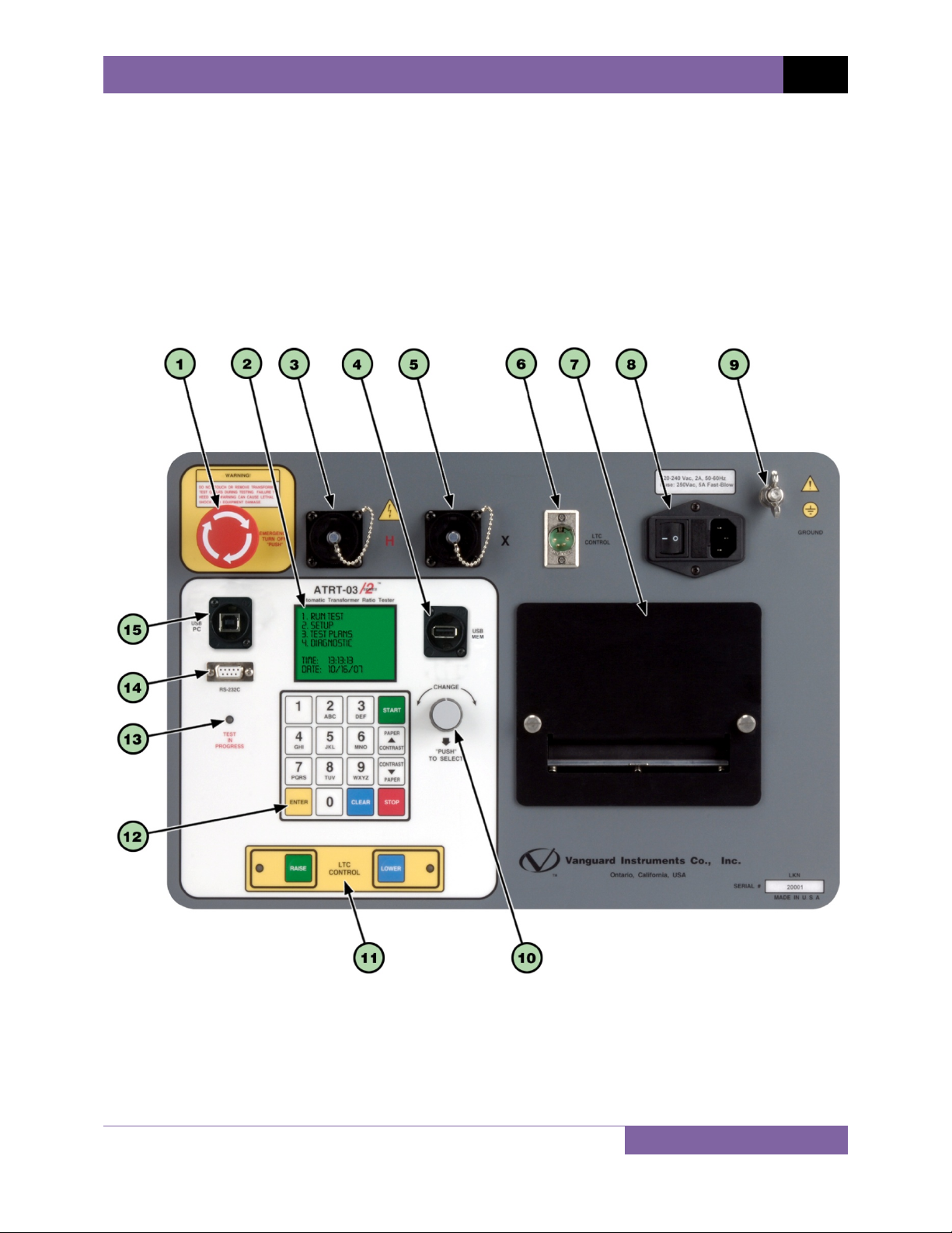
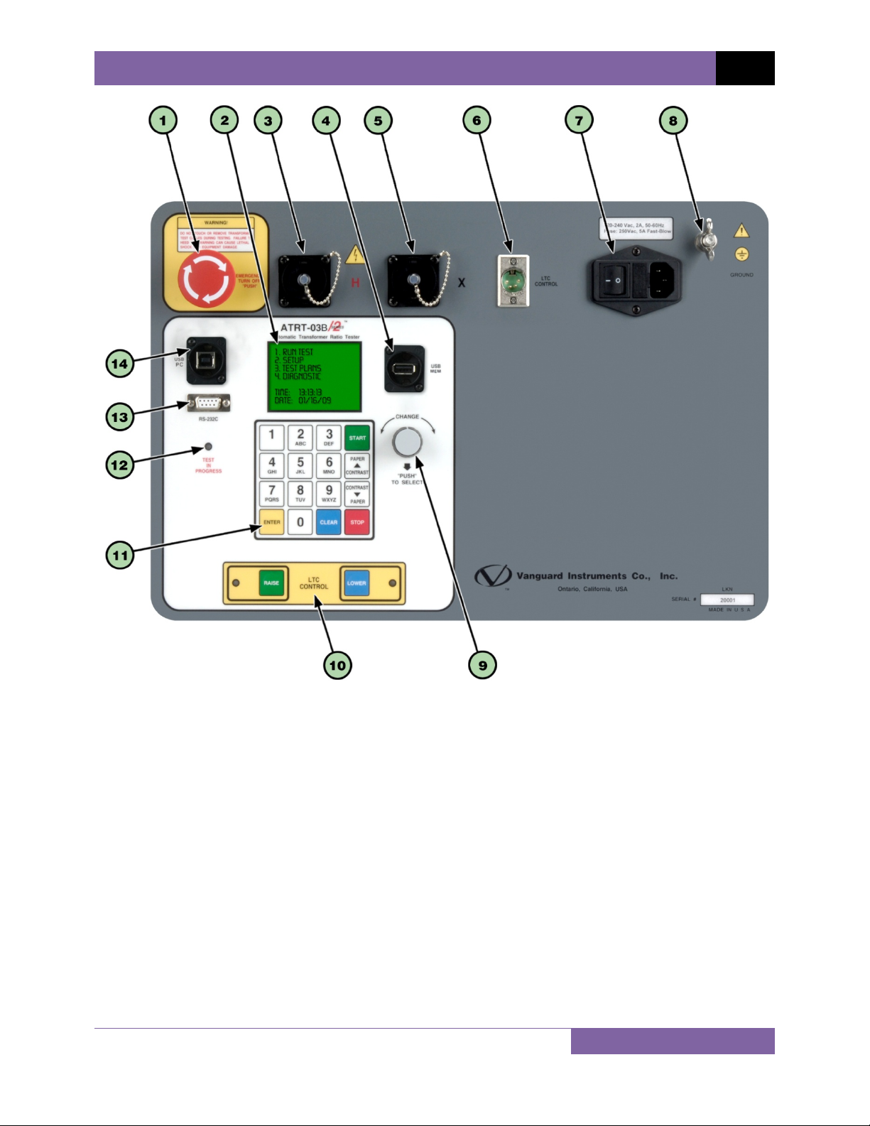
1.3 Controls and Indicators
The ATRT-03 S2, ATRT-03A S2, and ATRT-03B S2 controls and indicators are shown in Figure 1,
Figure 2, and Figure 3, respectively. A leader line with an index number points to each control
and indicator, which is cross-referenced to a functional description in the corresponding table.
The purpose of the controls and indicators may seem obvious, but users should familiarize
themselves with them before using the ATRT. Accidental misuse of the controls will usually
cause no serious harm. Users should also familiarize themselves with the safety summary
information found on the front page of this User’s Manual.
Figure 1. ATRT-03 S2 Controls and Indicators
7
Page 13

REV 2 ATRT-03 S2, ATRT-03A S2, AND ATRT-03B S2 USER’S MANUAL
Table 4. Functional Descriptions of ATRT-03 S2 Controls and Indicators
Item
Number
1
2
3
4
5
6
7
8
9
10
11
12
13
14
15
Panel Markings Functional Description
EMERGENCY
TURN OFF
“PUSH”
H H voltage connector.
USB
MEM
X X voltage connector.
LTC
CONTROL
4.5-inch wide thermal printer.
120-240 Vac, 2A, 50-60Hz
Fuse: 250Vac, 5A Fast-Blow
GROUND Ground stud for connecting to sub-station ground.
CHANGE
“PUSH”
TO SELECT
LTC
CONTROL
Rugged alpha-numeric keypad.
TEST
IN
PROGRESS
RS-232C RS-232C PC interface connector.
USB
PC
Emergency turn-off test voltage switch.
Back-lit LCD screen (62 x 128 dot graphic), viewable in bright sunlight
and low-light levels.
USB Flash drive interface port.
Load Tap Changer controller connector.
Input power connector and fused power switch with third-wire safety
ground.
Control knob. You can scroll through menu items by turning the
control knob. A highlighted menu item can be selected by pushing the
control knob.
Load Tap Changer control buttons.
This LED flashes in response to commands or when a test voltage is
applied to the test transformer.
USB PC interface connector.
8
Page 14
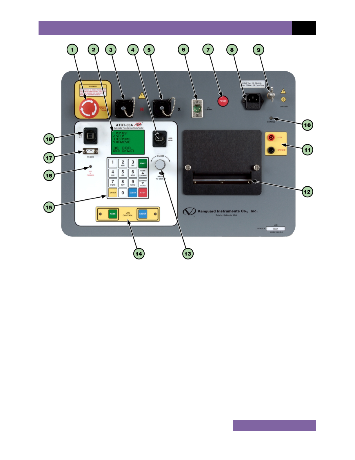
ATRT-03 S2, ATRT-03A S2, AND ATRT-03B S2 USER’S MANUAL REV 2
Figure 2. ATRT-03A S2 Controls and Indicators
9
Page 15

REV 2 ATRT-03 S2, ATRT-03A S2, AND ATRT-03B S2 USER’S MANUAL
Table 5. Functional Descriptions of ATRT-03A S2 Controls and Indicators
Item
Number
1
2
3
4
5
6
7
8
9
10
11
12
13
14
15
16
17
18
Panel Markings Functional Description
EMERGENCY
TURN OFF
“PUSH”
H H voltage connector.
USB
MEM
X X voltage connector
LTC
CONTROL
POWER Power switch
120-240 Vac, 2A, 50-60Hz
Fuse: 250Vac, 5A Fast-Blow
GROUND Ground stud for connecting to sub-station ground.
CHARGE LED is lit when internal batteries are being charged.
+12V
GROUND
4.5-inch wide thermal printer.
CHANGE
“PUSH”
TO SELECT
LTC
CONTROL
Rugged alpha-numeric keypad
TEST
IN
PROGRESS
RS-232C RS-232C PC interface connector.
USB
PC
Emergency turn off test voltage switch.
Back-lit LCD screen (64 x 128 dot graphic), viewable in bright sunlight
and low-light levels.
USB Flash drive interface port.
Load Tap Changer controller connector.
Input power connector with third-wire safety ground.
12 VDC input connectors.
Control knob. You can scroll through menu items by turning the control
knob. A highlighted menu item can be selected by pushing the control
knob.
Load Tap Changer control buttons.
This LED flashes in response to commands or when a test voltage is
applied to the test transformer.
USB PC interface connector.
10
Page 16
ATRT-03 S2, ATRT-03A S2, AND ATRT-03B S2 USER’S MANUAL REV 2
Figure 3. ATRT-03B S2 Controls and Indicators
11
Page 17

REV 2 ATRT-03 S2, ATRT-03A S2, AND ATRT-03B S2 USER’S MANUAL
Table 6. Functional Descriptions of ATRT-03B S2 Controls and Indicators
Item
Number
1
2
3
4
5
6
7
8
9
10
11
12
13
14
Panel Markings Functional Description
EMERGENCY
TURN-OFF
“PUSH”
H H voltage connector.
USB
MEM
X X voltage connector.
LTC
CONTROL
120-240 Vac, 2A, 50-60 Hz
Fuse: 250Vac, 5A Fast-Blow
GROUND Ground stud for connecting to sub-station ground.
CHANGE
“PUSH”
TO SELECT
LTC
CONTROL
Rugged alpha-numeric keypad.
TEST
IN
PROGRESS
RS-232C RS-232C PC interface connector.
USB
PC
Emergency turn off test voltage switch.
Back-lit LCD screen (64 x 128 dot graphic), viewable in bright sunlight
and low-light levels.
USB Flash drive interface port.
Load Tap Changer controller connector.
Input power connector and fused power switch with third-wire safety
ground.
Control knob. You can scroll through menu items by turning the control
knob. A highlighted menu item can be selected by pushing the control
knob.
Load Tap Changer control buttons.
This LED flashes in response to commands or when a test voltage is
applied to the test transformer.
USB PC interface connector.
12
Page 18

ATRT-03 S2, ATRT-03A S2, AND ATRT-03B S2 USER’S MANUAL REV 2
2.0 PRE-TEST SETUP
2.1 Operating Voltages
All three ATRT-03 S2 models can be powered by ac line voltage of 100-240 Vac, 50/60 Hz. For
greater flexibility, the ATRT-03A S2 features an internal rechargeable lead acid battery and can
also be powered by a 12 Vdc external source. The ATRT-03 S2 has built-in ground fault isolation
detection and will only operate with voltages that are ground-fault isolated.
2.2 LCD Screen Contrast Control
To increase the LCD screen contrast, press and hold the [PAPER ∧ Contrast] key for two
seconds. Release the button when the desired contrast level has been reached.
To decrease the LCD screen contrast, press and hold the [PAPER ∨ Contrast] key for two
seconds. Release the button when the desired contrast level has been reached.
2.3 Printer Paper Control
To advance the thermal printer paper, press and release the [PAPER ∧ Contrast] key.
To retract the thermal printer paper, press and release the [PAPER ∨ Contrast] key.
2.4 Printer Paper
The ATRT-03 S2 and ATRT-03A S2’s built-in thermal printers use 4.5-inch wide thermal paper for
printing test results. To maintain the highest print quality and to avoid paper jams, the use of
thermal paper supplied by Vanguard Instruments Company is highly recommended. Additional
paper can be ordered from the following sources:
Vanguard Instruments Co, Inc.
1520 S. Hellman Avenue
Ontario, CA 91761
Tel: 909-923-9390
Fax: 909-923-9391
Part Number: VIC TP-4 paper
BG Instrument Co.
13607 E. Trent Avenue
Spokane, WA 99216
Tel: 509-893-9881
Fax: 509-893-9803
Part Number: VIC TP-4 paper
13
Page 19
REV 2 ATRT-03 S2, ATRT-03A S2, AND ATRT-03B S2 USER’S MANUAL
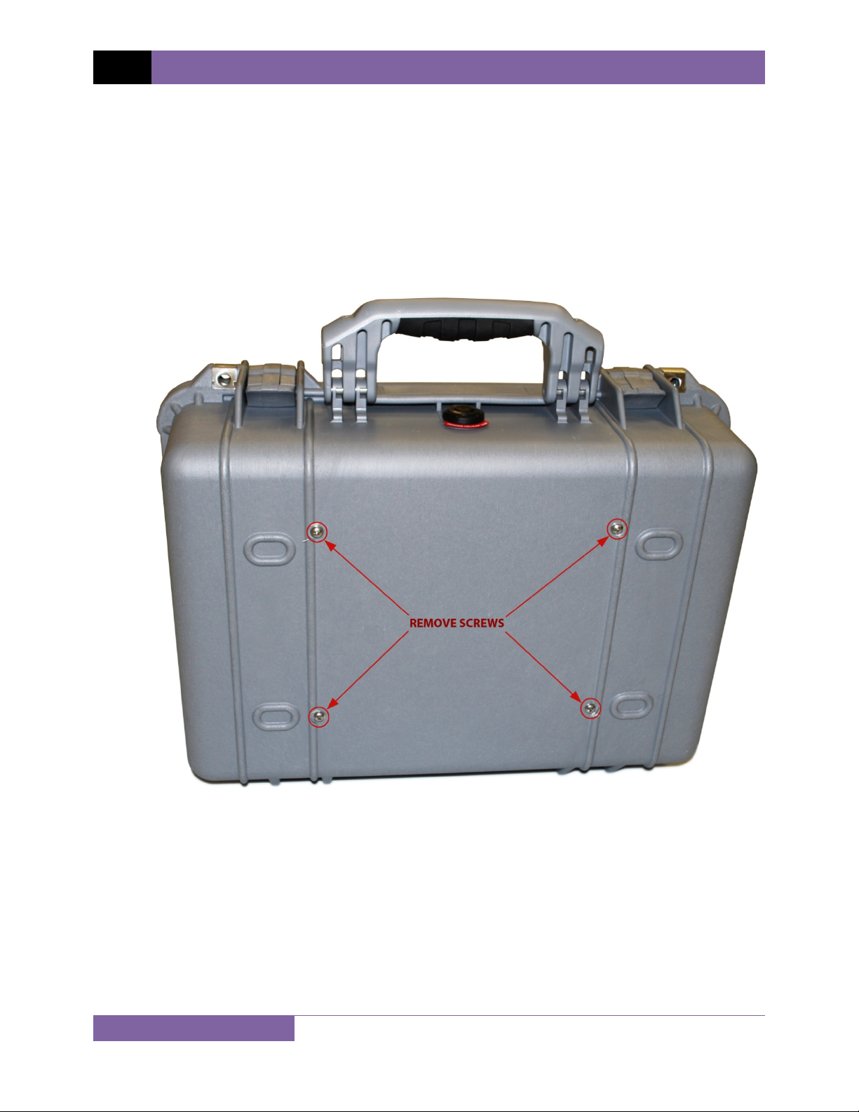
2.5 Replacing the Load Tap Changer Controller Fuses
The ATRT-03 S2 features a built-in Load Tap Changer (LTC) controller that can raise or lower the
LTC tap position from the front panel. The LTC controller circuit uses two 250 Vac/2A, NO, relay
contacts to simulate the LTC Raise/Lower switches. Each relay contact is protected by a 1A/250
Vac fuse (5 X 20mm, fast acting). The fuse should be replaced with a Littlefuse P/N 217001 or
equivalent. Follow the instructions below to replace the LTC controller fuses:
a. Remove the ATRT-03 S2 from its casing by removing the four screws from the bottom of
the case:
14
Page 20
ATRT-03 S2, ATRT-03A S2, AND ATRT-03B S2 USER’S MANUAL REV 2
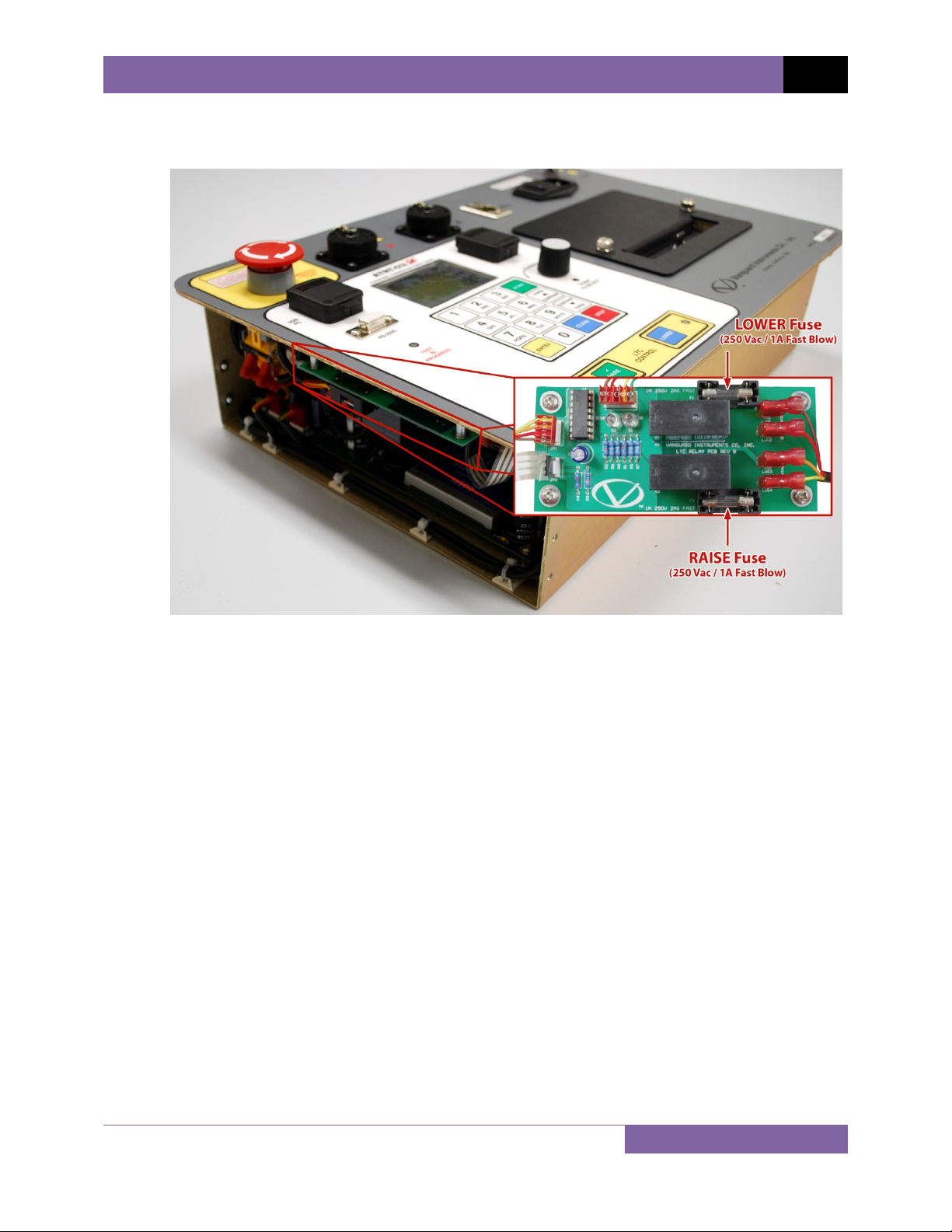
b. The LTC control board is located under the left side of the front panel as shown in the
figure below. Flip the unit over to easily access the LTC control board fuses.
c. Replace any fuses as necessary with Littlefuse P/N 217001 or equivalent (250 Vac/1A, 5
X 20mm fast-acting type).
d. Re-secure the unit in its casing with the screws that were removed in step a.
15
Page 21
REV 2 ATRT-03 S2, ATRT-03A S2, AND ATRT-03B S2 USER’S MANUAL
3.0 OPERATING PROCEDURES
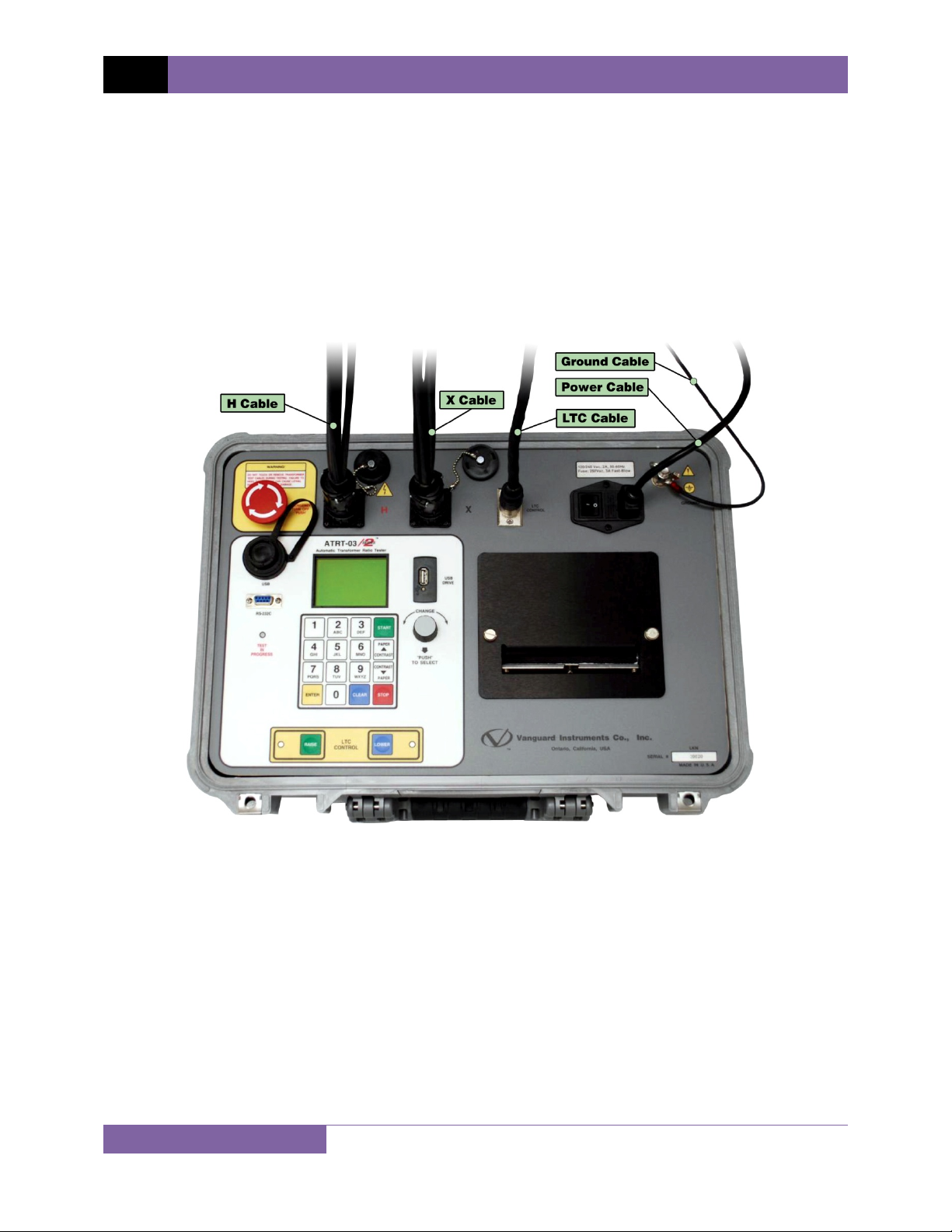
The ATRT-03 S2 should always be grounded with the provided ground cable before connecting
H and X cables. The transformer bushings should also be grounded before connecting test leads
to the transformer. This will prevent inducing any voltages into the ATRT-03 S2. All transformer
bus connections must be removed, and the transformer must be isolated before performing
any tests. Typical transformer connection diagrams are illustrated in the sections below.
3.1 Connection Diagrams
3.1.1. Typical Front Panel Connections
16
Figure 4. Typical Front Panel Cable Connections
Page 22
ATRT-03 S2, ATRT-03A S2, AND ATRT-03B S2 USER’S MANUAL REV 2
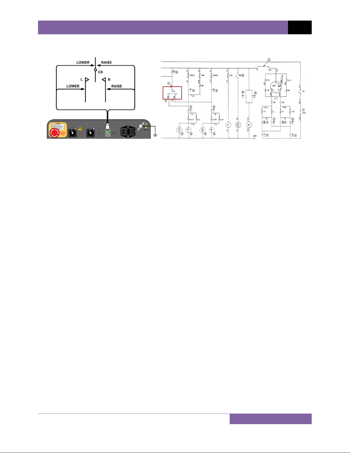
3.1.2. Typical Connections to a Load Tap Changer (LTC)
Figure 5. Typical Connections to a Load Tap Changer (LTC)
17
Page 23
REV 2 ATRT-03 S2, ATRT-03A S2, AND ATRT-03B S2 USER’S MANUAL
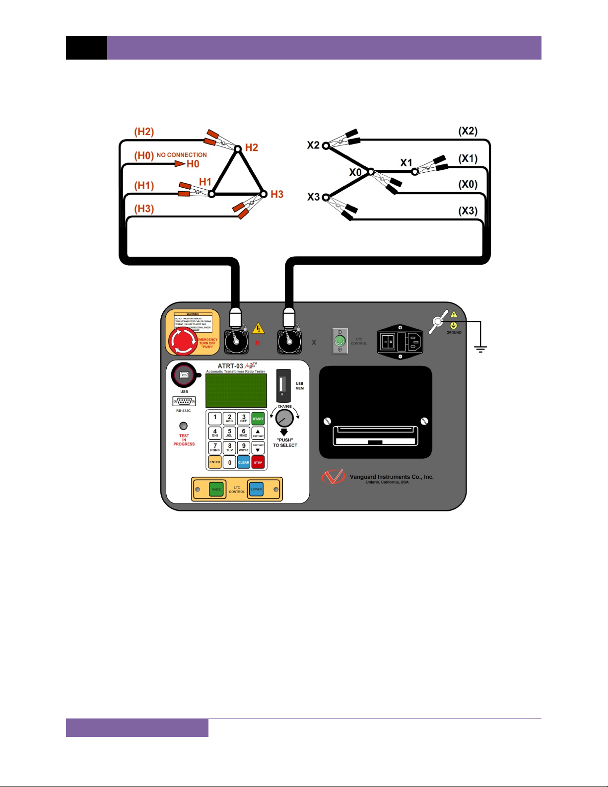
3.1.3. Typical Connections to a Delta-Wye Transformer
Figure 6. Typical H & X Cable Connections to a Delta-Wye Transformer
18
Page 24
ATRT-03 S2, ATRT-03A S2, AND ATRT-03B S2 USER’S MANUAL REV 2
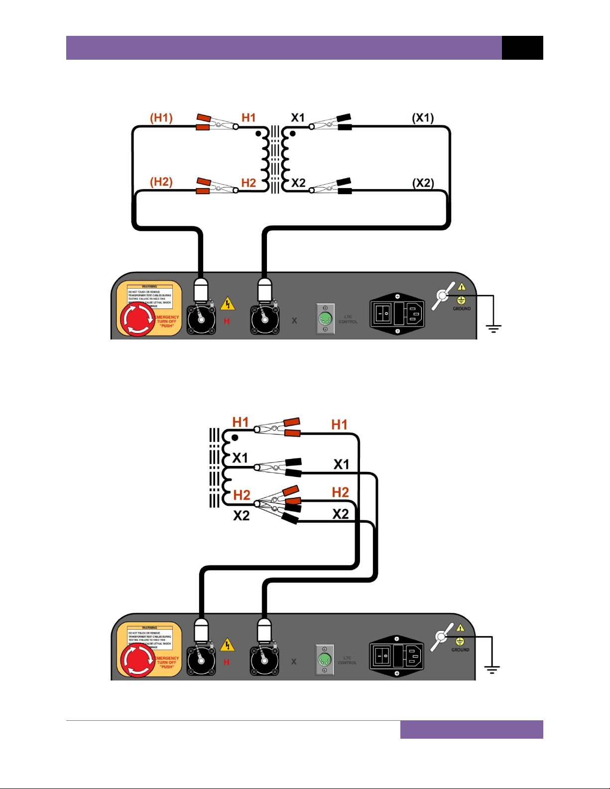
3.1.4. Typical Connections to a Single Phase Transformer
Figure 7. Typical Connections to a Single Phase Transformer
Figure 8. Typical Connections to a Single Phase Auto Transformer
19
Page 25
REV 2 ATRT-03 S2, ATRT-03A S2, AND ATRT-03B S2 USER’S MANUAL
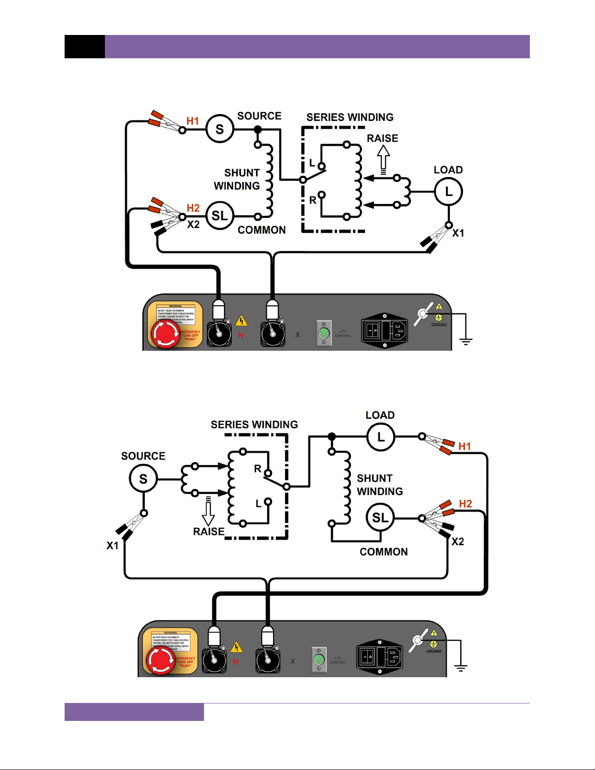
3.1.5. Typical Connections to a Voltage Regulator
Figure 9. Typical Connections to a Type A Voltage Regulator
Figure 10. Typical Connections to a Type B Voltage Regulator
20
Page 26
ATRT-03 S2, ATRT-03A S2, AND ATRT-03B S2 USER’S MANUAL REV 2
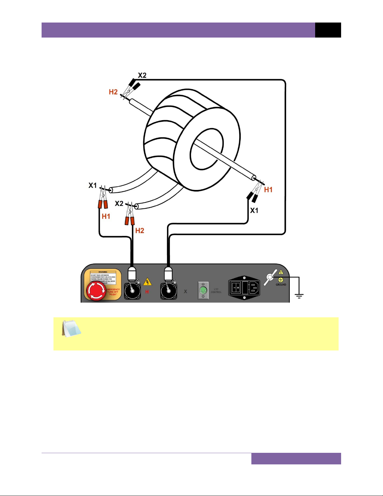
3.1.6. Typical Connections to a Donut Type (un-mounted) Current Transformer
Figure 11. Typical Connections to a Donut Type (un-mounted) Current Transformer (CT)
The H and X test leads are reversed for the CT ratio test connections shown
above.
NOTE
21
Page 27
REV 2 ATRT-03 S2, ATRT-03A S2, AND ATRT-03B S2 USER’S MANUAL
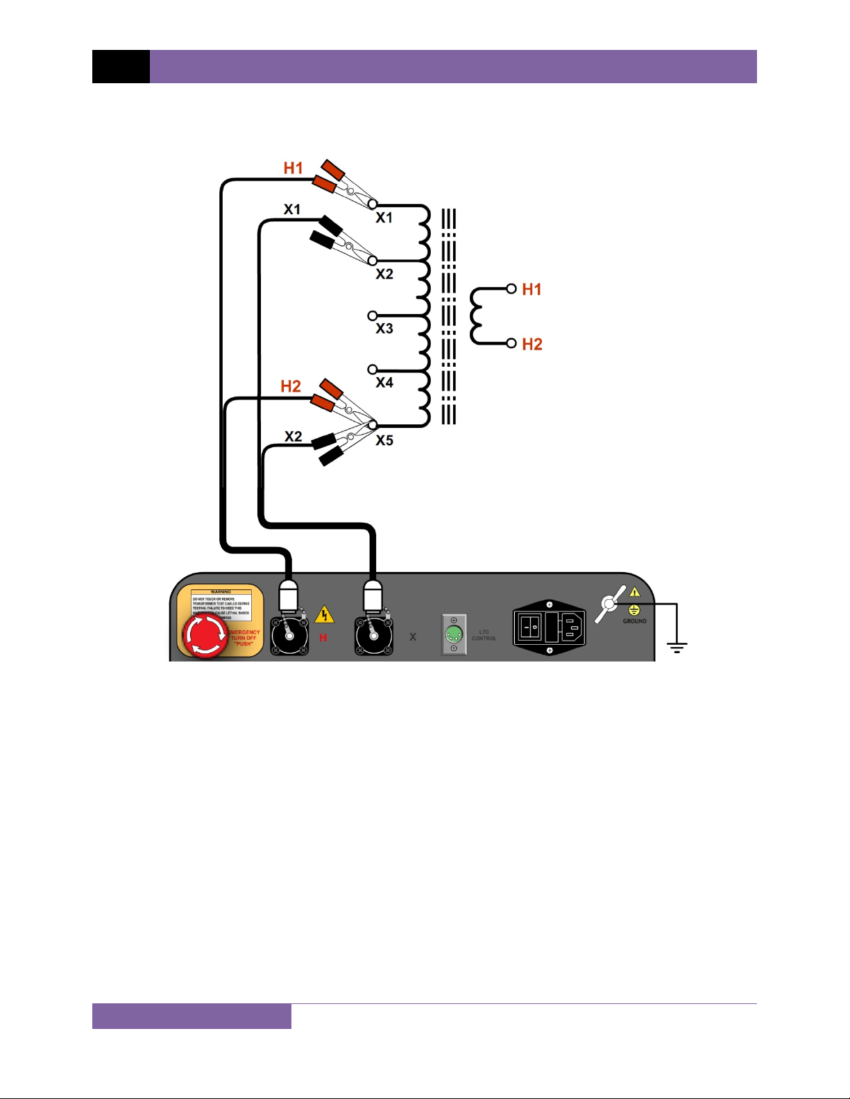
3.1.7. Typical Connections to a Multi-Tap Current Transformer
Figure 12. Typical Connections to a Multi-Tap Current Transformer
22
Page 28
ATRT-03 S2, ATRT-03A S2, AND ATRT-03B S2 USER’S MANUAL REV 2
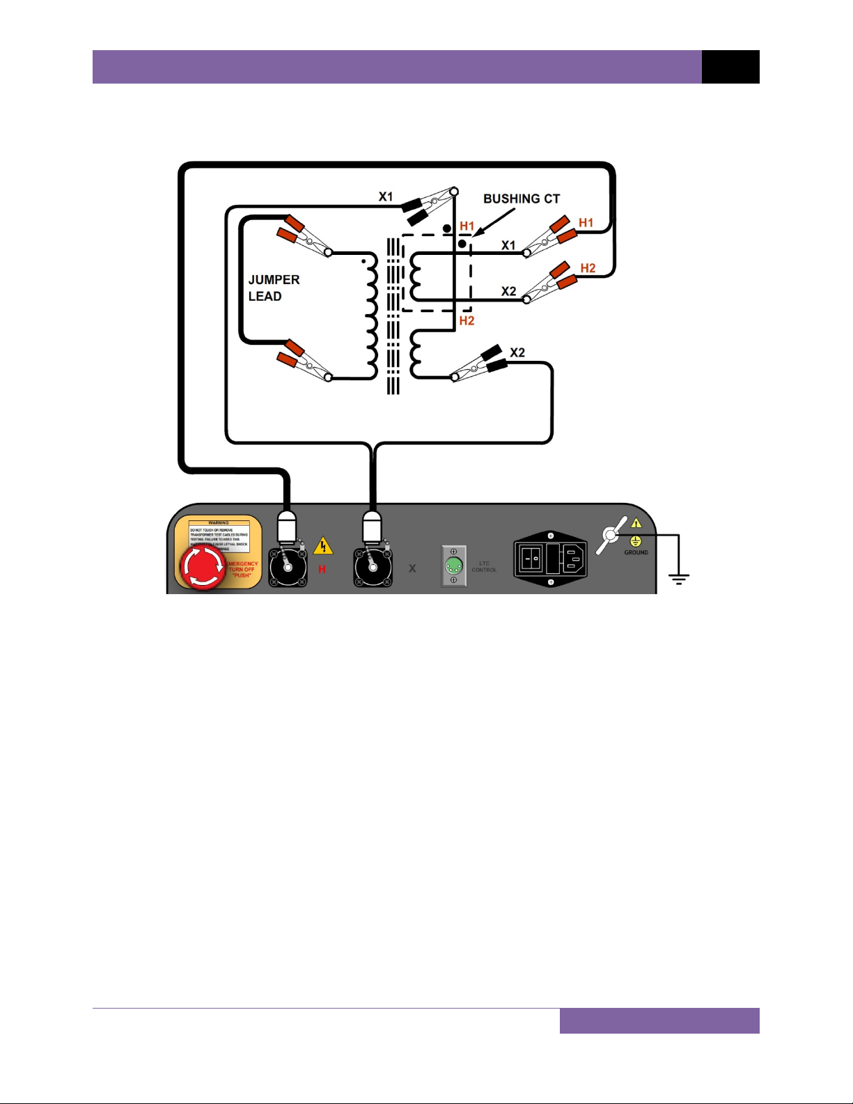
3.1.8. Typical Connections to a Bushing Mount CT on a Single Phase Transformer
Figure 13. Typical Connections to a Bushing Mount CT on a Single Phase Transformer
23
Page 29
REV 2 ATRT-03 S2, ATRT-03A S2, AND ATRT-03B S2 USER’S MANUAL
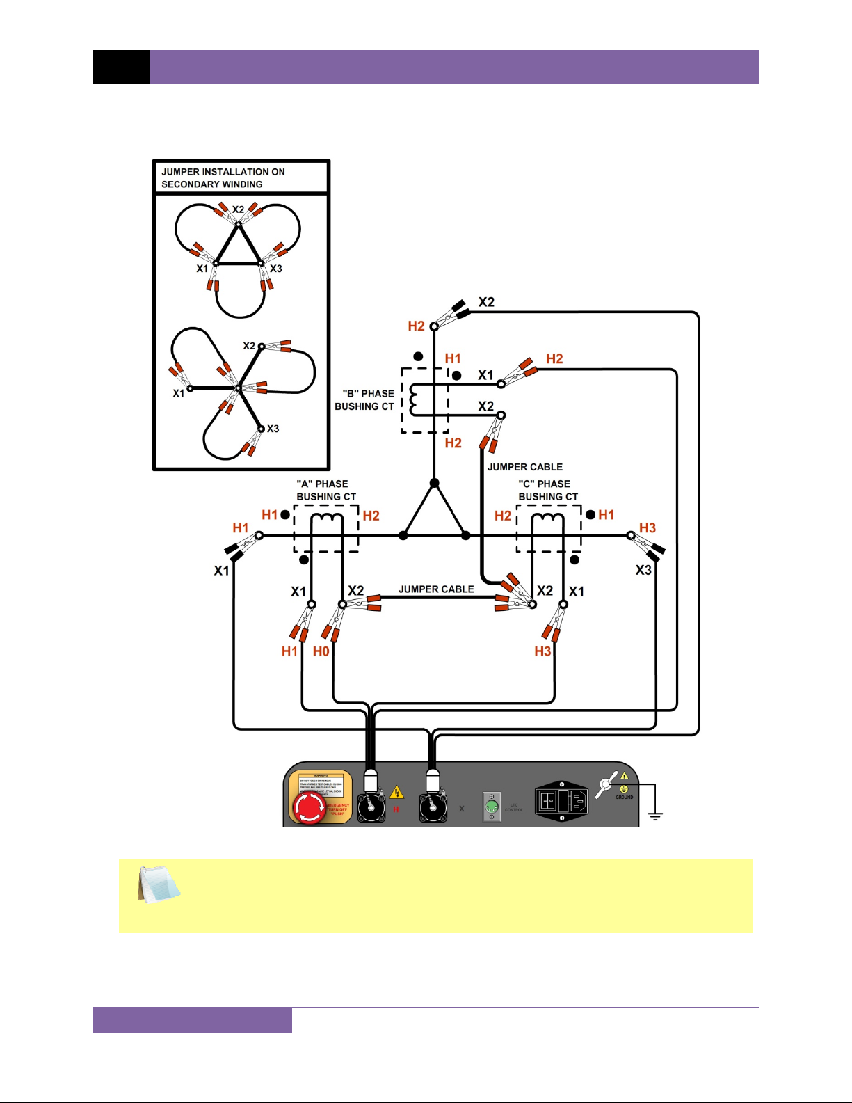
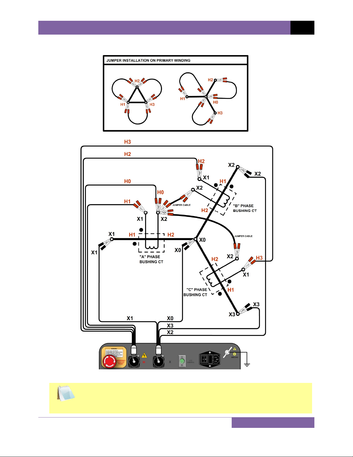
3.1.9. Typical Connections to Bushing Mount CT’s on Delta Transformer
Figure 14. Typical Connections to Bushing Mount CT's on Delta Transformer
The CT turns-ratio is obtained by performing a Ynd11 test.
NOTE
24
Page 30
ATRT-03 S2, ATRT-03A S2, AND ATRT-03B S2 USER’S MANUAL REV 2
3.1.10. Typical Connections to Bushing Mount CT’s on Wye Transformer
Figure 15. Typical Connections to Bushing Mount CT's on Wye Transformer
The CT turns-ratio is obtained by performing a Ynyn0 test.
NOTE
25
Page 31

REV 2 ATRT-03 S2, ATRT-03A S2, AND ATRT-03B S2 USER’S MANUAL
3.2 Setting the Test Voltage
The ATRT-03 S2 offers three test voltages, 8 Vac, 40 Vac, and 100 Vac. The unit always defaults
to 40 Vac at power-on. The 8 Vac test voltage is for testing transformers which require low test
voltages, such as metering Current Transformers (CT’s). For metering CT’s, higher voltages may
drive the CT’s into saturation, thus giving invalid results. The 40 Vac test voltage is
recommended for testing power transformers. The 100 Vac test voltage is recommended for
testing power transformers in noisy environments. Follow the steps below to set the test
voltage:
a. Turn on the unit and start from the “ START-UP” menu:
1. RUN TEST
2. SETUP
3. TEST PLANS
4. DIAGNOSTIC
TIME: 11:23:01
DATE: 07/20/10
Press the
[2]
key (SETUP).
You can select menu options by typing the corresponding option number using
the alpha-numeric keypad or by using the control knob. To select menu
NOTE
options using the control knob, turn the knob clockwise or counter-clockwise
to highlight the next or previous menu item respectively. Once the desired
menu option is highlighted, push the control knob to select it.
b. The following screen will be displayed:
1. RECORD ID
2. TEST VOLTAGE
3. PRINT RECORD
4. SAVE/RESTORE RECORD
5. SET TIME
1. RECORD ID
2. TEST VOLTAGE
3. DISPLAY RECORD
4. SAVE/RESTORE RECORD
5. SET TIME
ATRT-03 S2 and ATRT-03A S2 ATRT-03B S2
[2]
Press the
key (TEST VOLTAGE).
26
Page 32

ATRT-03 S2, ATRT-03A S2, AND ATRT-03B S2 USER’S MANUAL REV 2
c. The following screen will be displayed:
1. 8 Volts
2. 40 volts
3. 100 volts
Select the desired test voltage by pressing the corresponding key on the numeric keypad
([1], [2], or [3]).
d. The voltage will be set and the following confirmation message will be displayed:
40 volts set
Press any key to return to the “START-UP” menu.
27
Page 33

REV 2 ATRT-03 S2, ATRT-03A S2, AND ATRT-03B S2 USER’S MANUAL
3.3 Setting the Date and Time
To set the date and time:
a. Start from the “START-UP” menu:
1. RUN TEST
2. SETUP
3. TEST PLANS
4. DIAGNOSTIC
TIME: 11:23:01
DATE: 07/20/10
Press the [2] key (SETUP).
b. The following screen will be displayed:
1. RECORD ID
2. TEST VOLTAGE
3. PRINT RECORD
4. SAVE/RESTORE RECORD
5. SET TIME
Press the [5] key (SET TIME).
c. The following screen will be displayed:
ENTER DATE
MM-DD-YY
Enter the date using the alpha-numeric keypad.
d. The following screen will be displayed:
ENTER TIME
HH:MM:SS
Enter the current time using the alpha-numeric keypad. When the complete time has
been entered, you will be immediately returned to the “START-UP” menu.
28
Page 34

ATRT-03 S2, ATRT-03A S2, AND ATRT-03B S2 USER’S MANUAL REV 2
3.4 Performing Tests
3.4.1. Entering Test Record Header Information
You can enter the test record header information before performing tests. The record header
includes identifying information such as the company, station, circuit, manufacturer, etc. Once
the header information has been set, it will apply to all subsequent test records. To enter the
header information:
a. Start from the “START-UP” menu:
1. RUN TEST
2. SETUP
3. TEST PLANS
4. DIAGNOSTIC
TIME: 11:23:01
DATE: 07/20/10
Press the [2] key (SETUP).
b. The following screen will be displayed:
1. RECORD ID
2. TEST VOLTAGE
3. PRINT RECORD
4. SAVE/RESTORE RECORD
5. SET TIME
1. RECORD ID
2. TEST VOLTAGE
3. DISPLAY RECORD
4. SAVE/RESTORE RECORD
5. SET TIME
ATRT-03 S2 and ATRT-03A S2 ATRT-03B S2
Press the [1] key (RECORD ID).
c. The following screen will be displayed:
COMPANY:
_
↑/↓ TO POSITION
"ENTER" TO ACCEPT
Type the company name using the alpha-numeric keypad.
When pressing a key, the corresponding number on the key will be displayed first.
Pressing the key again will display the first letter on the key. Pressing the key again will
display the second letter on the key. For example, to type the letter “A”, you must press
[2] key twice. To erase the character at the cursor position, press the [CLEAR] key.
the
Press the
[PAPER ∧ Contrast] key to move to the next character. Press the [PAPER
29
Page 35

REV 2 ATRT-03 S2, ATRT-03A S2, AND ATRT-03B S2 USER’S MANUAL
∨ Contrast] key to move to the previous character. Press the [ENTER] key when you
are done typing the company name.
d. The following screen will be displayed:
STATION:
_
↑/↓ TO POSITION
"ENTER" TO ACCEPT
Type the station name using the alpha-numeric keypad and then press the [ENTER]
key.
e. The following screen will be displayed:
CIRCUIT:
_
↑/↓ TO POSITION
"ENTER" TO ACCEPT
Type the circuit information using the alpha-numeric keypad and then press the
[ENTER] key.
f. The following screen will be displayed:
MANUFACTURER:
_
↑/↓ TO POSITION
"ENTER" TO ACCEPT
Type the manufacturer name using the alpha-numeric keypad and then press the
[ENTER] key.
30
Page 36

ATRT-03 S2, ATRT-03A S2, AND ATRT-03B S2 USER’S MANUAL REV 2
g. The following screen will be displayed:
MODEL:
_
↑/↓ TO POSITION
"ENTER" TO ACCEPT
Type the transformer’s model information using the alpha-numeric keypad and then
press the [ENTER] key.
h. The following screen will be displayed:
SERIAL NUMBER:
_
↑/↓ TO POSITION
"ENTER" TO ACCEPT
Type the transformer’s serial number using the alpha-numeric keypad and then press
the [ENTER] key.
i. The following screen will be displayed:
KVA RATING:
_
↑/↓ TO POSITION
"ENTER" TO ACCEPT
Type the transformer’s KVA rating using the alpha-numeric keypad and then press the
[ENTER] key.
31
Page 37

REV 2 ATRT-03 S2, ATRT-03A S2, AND ATRT-03B S2 USER’S MANUAL
j. The following screen will be displayed:
OPERATOR:
_
↑/↓ TO POSITION
"ENTER" TO ACCEPT
Type the operator’s name using the alpha-numeric keypad and then press the [ENTER]
key. All header information will be saved, and you will be returned to the “START-UP”
menu.
32
Page 38

ATRT-03 S2, ATRT-03A S2, AND ATRT-03B S2 USER’S MANUAL REV 2
3.4.2. Testing a Single Phase Transformer
Follow the steps below to test a single phase transformer:
a. Start from the “START-UP” menu:
1. RUN TEST
2. SETUP
3. TEST PLANS
4. DIAGNOSTIC
TIME: 15:45:15
DATE: 07/20/10
Press the
[1]
key (RUN TEST).
b. The following screen will be displayed:
XFMR CONFIG:
1. SINGLE PHASE
2. Dy
3. Yd
4. Dd
5. yy
6. next page
Press the
[1]
key (SINGLE PHASE).
c. The following screen will be displayed:
NAME PLATE VOLTAGE?
1. YES
2. NO
If you had entered name plate voltages for a previous test, the following
screen will be displayed instead of the above screen:
NOTE
NAME PLATE VOLTAGE?
1. YES
2. NO
3. USE PREV DATA
Press the
[3]
key if you would like to use the name plate voltage values from
the previous test performed. Continue to step d.
33
Page 39

REV 2 ATRT-03 S2, ATRT-03A S2, AND ATRT-03B S2 USER’S MANUAL
1. YES
Press the [1] key (YES) if you would like to enter the transformer name plate
voltage values. The following screen will be displayed.
NAME PLATE VOLTAGE:
H : X
0 :
Type the H winding name plate voltage value using the numeric keypad. The
screen will be updated as shown below:
NAME PLATE VOLTAGE:
H : X
2,400 :
Press the [ENTER] key. The screen will be updated as shown below:
NAME PLATE VOLTAGE:
H : X
2,400 : 0
Type the X winding name plate voltage value using the numeric keypad. The
screen will be updated as shown below:
NAME PLATE VOLTAGE:
H : X
2,400 : 240
Press the [ENTER] key. Continue to step d.
2. NO
Press the [2] key (NO) if you do not want to enter the transformer name plate
voltage values. Continue to step d.
34
Page 40

ATRT-03 S2, ATRT-03A S2, AND ATRT-03B S2 USER’S MANUAL REV 2
d. The following screen will be displayed:
"START" TO TEST
OR
"STOP" TO ABORT
Press the
[START]
key to initiate the test.
e. The following screen will be displayed while the test is being performed:
test in progress
please wait...
The test results will be displayed on the LCD screen when testing has finished:
RATIO mA %DIFF
+10.004 0004 0.04
The polarity is displayed as either a plus sign (+) for “in-phase” or a minus sign (-) for
“out-of-phase”. The value listed under “% DIFF” is the percentage error.
The percentage error (% DIFF) is calculated as the absolute value of:
[(Calculated Ratio – Measured Ratio) / Calculated Ratio)] x 100
NOTE
Press any key to continue.
If using an ATRT-03 S2 or ATRT-03A S2, continue to step f.
If using an ATRT-03B S2, continue to step h.
35
Page 41

REV 2 ATRT-03 S2, ATRT-03A S2, AND ATRT-03B S2 USER’S MANUAL
f. The following screen will be displayed:
PRINT TEST RESULTS?
1. YES
2. NO
Press the [1] key (YES) to print the test results.
g. The following screen will be displayed:
PRINT FORMAT?
1. COLUMN
2. DETAILED
Press the [1] key (COLUMN) to print a columnar report (see Figure 16) or press the [2]
key (DETAILED) to print a detailed report (see Figure 17).
h. The following screen will be displayed:
KEEP THIS READING?
1. YES
2. NO
Press the
[1] key (YES) to save the reading.
i. The following screen will be displayed:
TEST SAVED
Press any key to continue.
36
Page 42

ATRT-03 S2, ATRT-03A S2, AND ATRT-03B S2 USER’S MANUAL REV 2
The above screen will be displayed if there is currently no data in the unit’s
memory buffer. If a test was previously performed or a test record was
NOTE
restored from Flash EEPROM or from a Flash drive, the following screen will
be displayed instead:
PREVIOUS DATA IN BUF
1. APPEND PREV. DATA
2. CLEAR PREV. DATA
Press the
working memory to the current test results, or press the
[1]
key (APPEND PREV. DATA) to append the data in the unit’s
[2]
key (CLEAR PREV.
DATA) to clear any previous data from the unit’s memory buffer and only save
the current test results.
The following screen will then be displayed:
TEST SAVED
Press any key to continue.
j. The following screen will be displayed:
RUN ANOTHER TEST?
1. YES
2. NO
3. REPEAT PREV. TEST
[2]
Press the
key (NO).
37
Page 43

REV 2 ATRT-03 S2, ATRT-03A S2, AND ATRT-03B S2 USER’S MANUAL
k. The following screen will be displayed:
SAVE THIS RECORD?
1. YES
2. NO
Press the
[1]
key (YES) to save the test record to the unit’s Flash EEPROM.
l. The following screen will be displayed momentarily:
SAVING RECORD...
PLEASE WAIT...
The following confirmation screen will then be displayed:
RECORD NUMBER 1
HAS BEEN SAVED!
The unit will automatically assign the record number and will not over-write
existing test records.
NOTE
Press any key to return to the “START-UP” menu.
38
Page 44

ATRT-03 S2, ATRT-03A S2, AND ATRT-03B S2 USER’S MANUAL REV 2
Item
Number
1
2
3
4
5
6
7
8
9
10
11
Figure 16. Single Phase Test Results Printout - Column Format
(ATRT-03 S2 and ATRT-03A S2 only)
Table 7. Descriptions of Single Phase Test Results Elements (Column Format)
Description
Test record date and time.
Test record header information (see section 3.4.1).
Test voltage.
Type of transformer under test.
H tap voltage.
X tap voltage.
Calculated ratio.
Percentage error between the calculated ratio and the measured ratio.
Excitation current.
Measured ratio.
Winding polarity.
39
Page 45

REV 2 ATRT-03 S2, ATRT-03A S2, AND ATRT-03B S2 USER’S MANUAL
Figure 17. Single Phase Test Results Printout - Detailed Format
40
(ATRT-03 S2 and ATRT-03A S2 only)
Page 46

ATRT-03 S2, ATRT-03A S2, AND ATRT-03B S2 USER’S MANUAL REV 2
Table 8. Descriptions of Single Phase Test Results Elements (Detailed Format)
Item
Number
1
2
3
4
5
6
7
8
9
10
11
12
13
Description
Test record date and time.
Test record header information (see section 3.4.1).
Test voltage.
Type of transformer under test.
H tap voltage.
X tap voltage.
Calculated ratio.
Measured ratio.
Percentage error between the calculated ratio and the measured ratio.
Measured transformer turns ratio.
Measured voltage ratio.
Winding phase angle.
Excitation current.
41
Page 47

REV 2 ATRT-03 S2, ATRT-03A S2, AND ATRT-03B S2 USER’S MANUAL
3.4.3. Testing a Dyn1 (12,000 V/208 V) Transformer
Follow the steps below to test a Dyn1 (12,000 V/208 V) transformer:
a. Start from the “START-UP” menu:
1. RUN TEST
2. SETUP
3. TEST PLANS
4. DIAGNOSTIC
TIME: 15:45:15
DATE: 07/20/10
Press the [1] key (RUN TEST).
b. The following screen will be displayed:
XFMR CONFIG:
1. SINGLE PHASE
2. Dy
3. Yd
4. Dd
5. yy
6. next page
Press the [2] key (Dy).
c. The following screen will be displayed:
X0 ACCESSIBLE?
1. YES
2. NO
Press the [1] key (YES).
42
Page 48

ATRT-03 S2, ATRT-03A S2, AND ATRT-03B S2 USER’S MANUAL REV 2
d. The following screen will be displayed:
1. Dyn1
2. Dyn3
3. Dyn5
4. Dyn7
5. Dyn9
6. Dyn11
7. AUTO DETECT
Press the [1] key (Dyn1).
e. The following screen will be displayed:
NAME PLATE VOLTAGE?
1. YES
2. NO
1. YES
Press the [1] key (YES) if you would like to enter the transformer name plate
voltage values. The following screen will be displayed.
NAME PLATE VOLTAGE:
H : X
0 :
Type the H winding name plate voltage value using the numeric keypad. The
screen will be updated as shown below:
NAME PLATE VOLTAGE:
H : X
2,400 :
43
Page 49

REV 2 ATRT-03 S2, ATRT-03A S2, AND ATRT-03B S2 USER’S MANUAL
Press the [ENTER] key. The screen will be updated as shown below:
NAME PLATE VOLTAGE:
H : X
1,200 : 0
Type the X winding name plate voltage value using the numeric keypad. The
screen will be updated as shown below:
NAME PLATE VOLTAGE:
H : X
1,200 : 208
Press the [ENTER] key. Continue to step f.
2. NO
Press the [2] key (NO) if you do not want to enter the transformer name plate voltage
values. Continue to step f.
f. The following screen will be displayed:
"START" TO TEST
THREE PHASE OR
"STOP" TO ABORT
Press the
[START] key to initiate the test.
g. The following screen will be displayed while the test is being performed:
test in progress
please wait...
44
Page 50

ATRT-03 S2, ATRT-03A S2, AND ATRT-03B S2 USER’S MANUAL REV 2
The screen will be updated with the Phase A test results as shown:
TEST RESULTS:
RATIO
A +100.04 0002 0.11
XFMR TYPE: Dyn1
mA %DIFF
Testing will continue, and the screen will be updated with the Phase B test results as
shown:
TEST RESULTS:
RATIO
A +100.04 0002 0.11
B +100.05 0002 0.12
XFMR TYPE: Dyn1
mA %DIFF
Finally, the screen will be updated with the Phase C test results as shown:
TEST RESULTS:
RATIO
A +100.04 0002 0.11
B +100.05 0002 0.12
C +100.01 0002 0.09
XFMR TYPE: Dyn1
mA %DIFF
Press any key to continue.
If using an ATRT-03 S2 or ATRT-03A S2, continue to step h.
If using an ATRT-03B S2, continue to step j.
h. The following screen will be displayed:
PRINT TEST RESULTS?
1. YES
2. NO
Press the [1] key (YES) to print the test results.
45
Page 51

REV 2 ATRT-03 S2, ATRT-03A S2, AND ATRT-03B S2 USER’S MANUAL
i. The following screen will be displayed:
PRINT FORMAT?
1. COLUMN
2. DETAILED
Press the
[1] key (COLUMN) to print a columnar report (see Figure 18) or press the [2]
key (DETAILED) to print a detailed report (see Figure 19).
j. The following screen will be displayed:
KEEP THIS READING?
1. YES
2. NO
Press the
[1] key (YES) to save the reading.
k. The following screen will be displayed:
TEST SAVED
Press any key to continue.
l. The following screen will be displayed:
RUN ANOTHER TEST?
1. YES
2. NO
3. REPEAT PREV. TEST
Press the [2] key (NO).
46
Page 52

ATRT-03 S2, ATRT-03A S2, AND ATRT-03B S2 USER’S MANUAL REV 2
m. The following screen will be displayed:
SAVE THIS RECORD?
1. YES
2. NO
Press the [1] key (YES) to save the test record to the unit’s Flash EEPROM.
n. The following screen will be displayed momentarily:
SAVING RECORD...
PLEASE WAIT...
The following confirmation screen will then be displayed:
RECORD NUMBER 1
HAS BEEN SAVED!
Press any key to return to the “START-UP” menu.
47
Page 53

REV 2 ATRT-03 S2, ATRT-03A S2, AND ATRT-03B S2 USER’S MANUAL
48
Figure 18. Dyn1 Test Results Printout - Column Format
(ATRT-03 S2 and ATRT-03A S2 only)
Page 54

ATRT-03 S2, ATRT-03A S2, AND ATRT-03B S2 USER’S MANUAL REV 2
Table 9. Descriptions of Dyn1 Test Results Elements (Column Format)
Item
Number
1
2
3
4
5
6
7
8
9
10
11
12
Description
Test record date and time.
Test record header information (see section 3.4.1).
Test voltage.
Type of transformer under test.
Transformer configuration diagrams (H and X).
H tap voltage.
X tap voltage.
Calculated ratio.
Measured ratio, excitation current, phase angle, and percentage error for Phase A.
Measured ratio, excitation current, phase angle, and percentage error for Phase B.
Measured ratio, excitation current, phase angle, and percentage error for Phase C.
Winding polarity.
49
Page 55

REV 2 ATRT-03 S2, ATRT-03A S2, AND ATRT-03B S2 USER’S MANUAL
Figure 19. Dyn1 Test Results Printout - Detailed Format
(ATRT-03 S2 and ATRT-03 S2A only)
50
Page 56

ATRT-03 S2, ATRT-03A S2, AND ATRT-03B S2 USER’S MANUAL REV 2
Table 10. Descriptions of Dyn1 Test Results Elements (Detailed Format)
Item
Number
1
2
3
4
5
6
7
8
9
10
11
12
13
14
15
16
17
18
19
20
21
22
23
24
25
26
27
28
29
30
31
32
33
34
35
Description
Test record date and time.
Test record header information (see section 3.4.1).
Test voltage.
Type of transformer under test.
Transformer configuration diagrams.
Test H1-H3 and X1-X0 section heading.
H1-H3 tap voltage.
X1-X0 tap voltage.
H1-H3, X1-X0 calculated ratio.
H1-H3, X1-X0 measured ratio.
H1-H3, X1-X0 percentage error between calculated ratio and measured ratio.
H1-H3, X1-X0 transformer turns ratio.
H1-H3, X1-X0 voltage ratio.
H1-H3, X1-X0 measured phase angle.
H1-H3, X1-X0 measured excitation current.
Test H2-H1 and X2-X0 section heading
H2-H1 tap voltage.
X2-X0 tap voltage.
H2-H1, X2-X0 calculated ratio.
H2-H1, X2-X0 measured ratio.
H2-H1, X2-X0 percentage error between calculated ratio and measured ratio.
H2-H1, X2-X0 transformer turns ratio.
H2-H1, X2-X0 voltage ratio.
H2-H1, X2-X0 measured phase angle.
H2-H1, X2-X0 measured excitation current.
Test H3-H2 and X3-X0 section heading.
H3-H2 tap voltage.
X3-X0 tap voltage.
H3-H2, X3-X0 calculated ratio.
H3-H2, X3-X0 measured ratio.
H3-H2, X3-X0 percentage error between calculated ratio and measured ratio.
H3-H2, X3-X0 transformer turns ratio.
H3-H2, X3-X0 voltage ratio.
H3-H2, X3-X0 measured phase angle.
H3-H2, X3-X0 measured excitation current.
51
Page 57

REV 2 ATRT-03 S2, ATRT-03A S2, AND ATRT-03B S2 USER’S MANUAL
3.4.4. Testing a Three Phase Transformer Using Auto Detect Mode
The ATRT-03 S2 provides a convenient Auto Detect mode that can automatically detect 130
specific vector groups for different transformer types defined by ANSI, CEI/IEC, and Australian
standards. The transformer configurations supported are listed in Appendix A. The ATRT-03 S2
can detect the vector diagrams for Delta-Delta, Wye-Wye, Delta-Wye, and Wye-Delta
transformer types. Follow the steps below to test a three phase transformer using auto detect
mode:
a. Start from the “START-UP” menu:
1. RUN TEST
2. SETUP
3. TEST PLANS
4. DIAGNOSTIC
TIME: 15:45:15
DATE: 07/20/10
Press the [1] key (RUN TEST).
b. The following screen will be displayed:
XFMR CONFIG:
1. SINGLE PHASE
2. Dy
3. Yd
4. Dd
5. yy
6. next page
Select a supported three phase transformer type by pressing the corresponding numeric
key on the keypad (
[2], [3], [4], or [5]. For this example, we will perform a Yd test
(option 3).
c. The following screen will be displayed:
H0 ACCESSIBLE?
1. YES
2. NO
Press the
[1] key (YES).
52
Page 58

ATRT-03 S2, ATRT-03A S2, AND ATRT-03B S2 USER’S MANUAL REV 2
d. The following screen will be displayed:
1. YNd1
2. YNd3
3. YNd5
4. YNd7
5. YNd9
6. YNd111
7. AUTO DETECT
Press the [7] key (AUTO DETECT).
e. The following screen will be displayed:
NAME PLATE VOLTAGE?
1. YES
2. NO
1. YES
Press the [1] key (YES) if you would like to enter the transformer name plate
voltage values. The following screen will be displayed.
NAME PLATE VOLTAGE:
H : X
0 :
Type the H winding name plate voltage value using the numeric keypad. The
screen will be updated as shown below:
NAME PLATE VOLTAGE:
H : X
1,734 :
53
Page 59

REV 2 ATRT-03 S2, ATRT-03A S2, AND ATRT-03B S2 USER’S MANUAL
Press the [ENTER] key. The screen will be updated as shown below:
NAME PLATE VOLTAGE:
H : X
1,734 : 0
Type the X winding name plate voltage value using the numeric keypad. The
screen will be updated as shown below:
NAME PLATE VOLTAGE:
H : X
1,734 : 100
Press the [ENTER] key. Continue to step f.
2. NO
Press the [2] key (NO) if you do not want to enter the transformer name plate
voltage values. Continue to step f.
f. The following screen will be displayed:
"START" TO TEST
THREE PHASE OR
"STOP" TO ABORT
Press the
[START] key to initiate the test.
g. The following screen will be displayed while the unit determines the transformer
configuration:
YNd AUTO DETECT
TESTING YNd1
54
Page 60

ATRT-03 S2, ATRT-03A S2, AND ATRT-03B S2 USER’S MANUAL REV 2
The ATRT-03 S2 will start testing the transformer configurations starting with YNd1. If
the transformer is not a type YNd1, it will continue to test for the next type (YNd3,
YNd5, etc.) until the transformer type has been determined. The screen will be updated
as shown below to indicate which configuration is currently being tested for:
YNd AUTO DETECT
TESTING YNd3
Once the transformer type has been determined, the unit will start performing the test.
h. The screen will be updated with the Phase A test results as shown:
TEST RESULTS:
RATIO
A +10.057 0.8 0.46
XFMR TYPE: YNd1
mA %DIFF
Testing will continue, and the screen will be updated with the Phase B test results as
shown:
TEST RESULTS:
RATIO
A +10.057 0.8 0.46
B +10.046 0.7 0.34
XFMR TYPE: YNd1
mA %DIFF
55
Page 61

REV 2 ATRT-03 S2, ATRT-03A S2, AND ATRT-03B S2 USER’S MANUAL
Finally, the screen will be updated with the Phase C test results as shown:
TEST RESULTS:
RATIO
A +10.057 0.8 0.46
B +10.046 0.7 0.34
C +10.057 0.8 0.46
XFMR TYPE: YNd1
mA %DIFF
Press any key to continue.
If using an ATRT-03 S2 or ATRT-03A S2, continue to step i.
If using an ATRT-03B S2, continue to step k.
i. The following screen will be displayed:
PRINT TEST RESULTS?
1. YES
2. NO
Press the [1] key (YES) to print the test results.
j. The following screen will be displayed:
PRINT FORMAT?
1. COLUMN
2. DETAILED
Press the
[1] key (COLUMN) to print a columnar report or press the [2] key (DETAILED)
to print a detailed report.
k. The following screen will be displayed:
KEEP THIS READING?
1. YES
2. NO
Press the
[1] key (YES) to save the reading.
56
Page 62

ATRT-03 S2, ATRT-03A S2, AND ATRT-03B S2 USER’S MANUAL REV 2
l. The following screen will be displayed:
TEST SAVED
Press any key to continue.
m. The following screen will be displayed:
RUN ANOTHER TEST?
1. YES
2. NO
3. REPEAT PREV. TEST
Press the [2] key (NO).
n. The following screen will be displayed:
SAVE THIS RECORD?
1. YES
2. NO
Press the [1] key (YES) to save the test record to the unit’s Flash EEPROM.
o. The following screen will be displayed momentarily:
SAVING RECORD...
PLEASE WAIT...
57
Page 63

REV 2 ATRT-03 S2, ATRT-03A S2, AND ATRT-03B S2 USER’S MANUAL
The following confirmation screen will then be displayed:
RECORD NUMBER 4
HAS BEEN SAVED!
Press any key to return to the “START-UP” menu.
58
Page 64

ATRT-03 S2, ATRT-03A S2, AND ATRT-03B S2 USER’S MANUAL REV 2
3.5 Working With Test Records
3.5.1. Saving Test Results to a Test Record
After performing a test, the user is presented the option to save the test results to the unit’s
Flash EEPROM or to a USB Flash Drive. If the test results are not saved immediately after
performing a test, they will still remain in the working memory and can be saved later, as long
as a new test has not been performed and the unit has not been turned off. Follow the steps
below to save the test results from the working memory to a test record (the following
procedure can also be used to re-save a restored test record to a new memory location or to a
USB Flash Drive):
a. Perform a test or restore a test record to the working memory (see section 3.5.2 and
3.5.3), and then start from the “START-UP” menu:
1. RUN TEST
2. SETUP
3. TEST PLANS
4. DIAGNOSTIC
TIME: 15:45:15
DATE: 07/20/10
Press the [2] key (SETUP).
b. The following screen will be displayed:
1. RECORD ID
2. TEST VOLTAGE
3. PRINT RECORD
4. SAVE/RESTORE RECORD
5. SET TIME
1. RECORD ID
2. TEST VOLTAGE
3. DISPLAY RECORD
4. SAVE/RESTORE RECORD
5. SET TIME
ATRT-03 S2 and ATRT-03A S2 ATRT-03B S2
Press the [4] key (SAVE/RESTORE RECORD).
59
Page 65

REV 2 ATRT-03 S2, ATRT-03A S2, AND ATRT-03B S2 USER’S MANUAL
c. The following screen will be displayed:
1. RESTORE RECORD
2. SAVE RECORD
3. RECORD DIRECTORY
4. ERASE RECORD
Press the [2] key (SAVE RECORD).
If a USB Flash drive is connected to the unit, continue to step d.
If a USB Flash drive is NOT connected to the unit, continue to step e.
d. The following screen will be displayed:
1. SAVE INTERNALLY
2. SAVE TO THUMB DRIVE
1. SAVE INTERNALLY
Press the [1] key (SAVE INTERNALLY) to save the test record to the unit’s Flash
EEPROM. Continue to step e.
2. SAVE TO THUMB DRIVE
Press the [2] key (SAVE TO THUMB DRIVE) to save the test record to the
connected USB Flash drive. The following screen will be displayed:
REC_001 SAVED TO
THUMB DRIVE.
Press any key to return to the “START-UP” menu.
60
Page 66

ATRT-03 S2, ATRT-03A S2, AND ATRT-03B S2 USER’S MANUAL REV 2
e. The following screen will be displayed:
RECORD NUMBER 5
HAS BEEN SAVED!
Press any key to return to the “START-UP” menu.
61
Page 67

REV 2 ATRT-03 S2, ATRT-03A S2, AND ATRT-03B S2 USER’S MANUAL
3.5.2. Restoring a Test Record From Flash EEPROM
Use the steps below to restore a test record from the ATRT-03 S2’s Flash EEPROM to the
working memory:
a. Start from the “START-UP” menu:
1. RUN TEST
2. SETUP
3. TEST PLANS
4. DIAGNOSTIC
TIME: 15:45:15
DATE: 07/20/10
Press the [2] key (SETUP).
b. The following screen will be displayed:
1. RECORD ID
2. TEST VOLTAGE
3. PRINT RECORD
4. SAVE/RESTORE RECORD
5. SET TIME
1. RECORD ID
2. TEST VOLTAGE
3. DISPLAY RECORD
4. SAVE/RESTORE RECORD
5. SET TIME
ATRT-03 S2 and ATRT-03A S2 ATRT-03B S2
Press the [4] key (SAVE/RESTORE RECORD).
c. The following screen will be displayed:
1. RESTORE RECORD
2. SAVE RECORD
3. RECORD DIRECTORY
4. ERASE RECORD
Press the
[1] key (RESTORE RECORD).
62
Page 68

ATRT-03 S2, ATRT-03A S2, AND ATRT-03B S2 USER’S MANUAL REV 2
d. The following screen will be displayed:
RESTORE RECORD
1.ENTER RECORD NUMBER
2.SCROLL TO SELECT
If you have a USB Flash drive inserted in the ATRT-03 S2’s “USB MEM” port,
the following screen will be displayed instead of the above screen:
NOTE
1.INTERNAL STORAGE
2.THUMB DRIVE
Press the
[1]
key (INTERNAL STORAGE).
The following screen will be displayed:
RESTORE RECORD
1.ENTER RECORD NUMBER
2.SCROLL TO SELECT
Continue with the steps below.
1. ENTER RECORD NUMBER
Press the
[1]
key (ENTER RECORD NUMBER) if you know the record number that
you would like to restore.
1.1. The following screen will be displayed:
RESTORE RECORD
NUMBER:
Type the record number using the alpha-numeric keypad and then press
the
[ENTER]
key.
63
Page 69

REV 2 ATRT-03 S2, ATRT-03A S2, AND ATRT-03B S2 USER’S MANUAL
1.2. The following screen will be displayed:
RECORD RESTORED!
PRINT RECORD?
1.YES
2.NO
Press the [1] key (YES) to print the test record.
If using an ATRT-03 S2 or ATRT-03A S2, continue to step 1.3.
If using an ATRT-03B S2, continue to step 1.4.
1.3. The following screen will be displayed:
PRINT RECORD
1.PRINT TO LCD
2.PRINT TO PRINTER
Press the [1] key (PRINT TO LCD) to display the restored test record data
on the unit’s LCD screen. Continue to step 1.4.
Press the [2] key (PRINT TO PRINTER) to print the restored test record
data on the unit’s built-in thermal printer. The following screen will be
displayed:
PRINT FORMAT?
1.COLUMN
2.DETAILED
Press the
[1] key (COLUMN) to print the test report in columnar format, or
press the [2] key (DETAILED) to print the test report in detailed format.
The test report will be printed, and you will be returned to the “STARTUP” menu. The restored test record will remain loaded in the working
memory.
64
Page 70

ATRT-03 S2, ATRT-03A S2, AND ATRT-03B S2 USER’S MANUAL REV 2
1.4. The basic information about the restored test record will be displayed as
shown:
YNd1
Num Tests: 1
07/22/10 07:52:50
Press the [PAPER ∨ Contrast] key. The test record details will be
displayed as shown:
1 YNd1
8 volts
RATIO mA %DIFF
A +10.057 0.8 0.46
B +10.046 0.7 0.34
C +10.057 0.8 0.46
Press the [STOP] key to return to the “START-UP” menu. The restored
test record will remain loaded in the working memory.
2. SCROLL TO SELECT
Press the [2] key (SCROLL TO SELECT) to scroll through a directory of the stored
test records.
2.1. The following screen will be displayed:
RECORDS DIRECTORY
"UP" TO SCROLL FWD
"DWN" TO SCROLL RVS
Press the
[PAPER ∧ Contrast] button or the [PAPER ∨ Contrast]
key to display the next or previous test record, respectively.
65
Page 71

REV 2 ATRT-03 S2, ATRT-03A S2, AND ATRT-03B S2 USER’S MANUAL
The basic test record information will be displayed as shown:
#1 07/21/10 09:05
SINGLE PHASE
1 TESTS
When you have located the test record that you would like to restored,
press the [ENTER] key. Continue to step 1.2 on page 64.
66
Page 72

ATRT-03 S2, ATRT-03A S2, AND ATRT-03B S2 USER’S MANUAL REV 2
3.5.3. Restoring a Test Record From a USB Flash Drive
Use the steps below to restore a test record from a USB Flash drive to the ATRT-03 S2’s working
memory:
a. Make sure the USB Flash drive containing the test record(s) is inserted in the ATRT-03
S2’s USB Flash drive port (“USB MEM” port). Then start from the “START-UP” menu:
1. RUN TEST
2. SETUP
3. TEST PLANS
4. DIAGNOSTIC
TIME: 15:45:15
DATE: 07/20/10
Press the [2] key (SETUP).
b. The following screen will be displayed:
1. RECORD ID
2. TEST VOLTAGE
3. PRINT RECORD
4. SAVE/RESTORE RECORD
5. SET TIME
1. RECORD ID
2. TEST VOLTAGE
3. DISPLAY RECORD
4. SAVE/RESTORE RECORD
5. SET TIME
ATRT-03 S2 and ATRT-03A S2 ATRT-03B S2
Press the [4] key (SAVE/RESTORE RECORD).
c. The following screen will be displayed:
1. RESTORE RECORD
2. SAVE RECORD
3. RECORD DIRECTORY
4. ERASE RECORD
5. COPY TO THUMB DRIVE
Press the [1] key (RESTORE RECORD).
67
Page 73

REV 2 ATRT-03 S2, ATRT-03A S2, AND ATRT-03B S2 USER’S MANUAL
d. The following screen will be displayed:
1.INTERNAL STORAGE
2.THUMB DRIVE
Press the [2] key (THUMB DRIVE).
e. The following screen will be displayed:
RESTORE THUMB DRIVE
REC_
Type the record number that you would like to restore using the alpha-numeric keypad.
If you do not know the record number, you can first print (ATRT-03 S2 and ATRT-03A S2)
or display (ATRT-03B S2) a test record directory using the instructions in section 3.5.6
and 3.5.7.
Press the [ENTER] key.
f. The test record will be restored to the unit’s working memory and the following screen
will be displayed:
REC_000 restored!
PRINT RECORD?
1.YES
2.NO
Press the
[1] key (YES) to print or display the restored test record.
If using an ATRT-03 S2 or ATRT-03A S2, continue to step g.
If using an ATRT-03B S2, continue to step h.
68
Page 74

ATRT-03 S2, ATRT-03A S2, AND ATRT-03B S2 USER’S MANUAL REV 2
g. The following screen will be displayed:
PRINT RECORD
1.PRINT TO LCD
2.PRINT TO PRINTER
Press the
[1] key (PRINT TO LCD) to display the test record date on the unit’s LCD
screen. Continue to step h.
Press the
[2] key (PRINT TO PRINTER) to print the restored test record on the unit’s
built-in thermal printer. The following screen will be displayed:
PRINT FORMAT?
1.COLUMN
2.DETAILED
Press the [1] key (COLUMN) to print the test record in columnar format, or press the [2]
key (DETAILED) to print the test record in detailed format. The test record will be
printed, and you will be returned to the “START-UP” menu. The restored test record will
remain loaded in the unit’s working memory.
h. The basic information about the restored test record will be displayed as shown below:
YNd1
Num Tests: 1
07/22/10 07:52:50
69
Page 75

REV 2 ATRT-03 S2, ATRT-03A S2, AND ATRT-03B S2 USER’S MANUAL
Press the [PAPER ∨ Contrast] key. The test record details will be displayed as shown
below:
1 YNd1
8 volts
RATIO mA %DIFF
A +10.057 0.8 0.46
B +10.046 0.7 0.34
C +10.057 0.8 0.46
Press the [STOP] key to return to the “START-UP” menu. The restored test record will
remain loaded in the working memory.
70
Page 76

ATRT-03 S2, ATRT-03A S2, AND ATRT-03B S2 USER’S MANUAL REV 2
3.5.4. Copying Test Records to a USB Flash Drive
Use the steps below to copy one or all test records from the unit’s Flash EEPROM to a
connected USB Flash drive:
a. Make sure a USB Flash drive is connected to the unit’s “USB MEM” port, and then start
from the “START-UP” menu:
1. RUN TEST
2. SETUP
3. TEST PLANS
4. DIAGNOSTIC
TIME: 15:45:15
DATE: 07/20/10
Press the [2] key (SETUP).
b. The following screen will be displayed:
1. RECORD ID
2. TEST VOLTAGE
3. PRINT RECORD
4. SAVE/RESTORE RECORD
5. SET TIME
1. RECORD ID
2. TEST VOLTAGE
3. DISPLAY RECORD
4. SAVE/RESTORE RECORD
5. SET TIME
ATRT-03 S2 and ATRT-03A S2 ATRT-03B S2
Press the [4] key (SAVE/RESTORE RECORD).
c. The following screen will be displayed:
1. RESTORE RECORD
2. SAVE RECORD
3. RECORD DIRECTORY
4. ERASE RECORD
5. COPY TO THUMB DRIVE
Press the [5] key (COPY TO THUMB DRIVE).
71
Page 77

REV 2 ATRT-03 S2, ATRT-03A S2, AND ATRT-03B S2 USER’S MANUAL
d. The following screen will be displayed:
COPY REC TO THUMB DRV
1.COPY SINGLE RECORD
2.COPY ALL RECORDS
1. COPY SINGLE RECORD
Press the [1] key (COPY SINGLE RECORD) to copy a single test record from the
ATRT-03 S2’s Flash EEPROM to the connected USB Flash drive. The following
screen will be displayed:
ENTER RECORD NUMBER
TO COPY TO FLASH DRV
NUMBER:
Type the record number using the alpha-numeric keypad and then press the
[ENTER] key (If you don’t know the record number, you can first print or
display a test record directory using the instructions in section 3.5.6 and 3.5.7,
respectively). The test record will be copied to the USB Flash drive and the
following screen will be displayed:
REC_000 SAVED TO
THUMB DRIVE
Press any key to return to the “START-UP” menu.
2. COPY ALL RECORDS
Press the
[2] key (COPY ALL RECORDS) to copy all test records from the ATRT-03
S2’s Flash EEPROM to the connected USB Flash drive. All test records will be
copied from the unit to the connected USB Flash drive. The following screen will
be displayed when the process is finished:
72
Page 78

ATRT-03 S2, ATRT-03A S2, AND ATRT-03B S2 USER’S MANUAL REV 2
ALL RECORDS HAVE BEEN
TRANSFERRED TO THUMB
DRIVE!
Press any key to return to the “START-UP” menu.
73
Page 79

REV 2 ATRT-03 S2, ATRT-03A S2, AND ATRT-03B S2 USER’S MANUAL
3.5.5. Printing or Displaying a Test Record
You can print (ATRT-03 S2 and ATRT-03A S2 only) or display (all models) a test record at the
time that it is restored (see section 3.5.1 and 3.5.3), or you can restore it to the working
memory and print or display it later. To print or display the current test record in the working
memory:
a. Perform a test or restore a test record to the working memory (see section 3.5.1 and
3.5.3) and then start from the “START-UP” menu:
1. RUN TEST
2. SETUP
3. TEST PLANS
4. DIAGNOSTIC
TIME: 15:45:15
DATE: 07/20/10
Press the [2] key (SETUP).
b. The following screen will be displayed:
1. RECORD ID
2. TEST VOLTAGE
3. PRINT RECORD
4. SAVE/RESTORE RECORD
5. SET TIME
1. RECORD ID
2. TEST VOLTAGE
3. DISPLAY RECORD
4. SAVE/RESTORE RECORD
5. SET TIME
ATRT-03 S2 and ATRT-03A S2 ATRT-03B S2
Press the [3] key.
If using an ATRT-03 S2 or ATRT-03A S2, continue to step c.
If using an ATRT-03B S2, continue to step d.
74
Page 80

ATRT-03 S2, ATRT-03A S2, AND ATRT-03B S2 USER’S MANUAL REV 2
c. The following screen will be displayed:
PRINT RECORD
1.PRINT TO LCD
2.PRINT TO PRINTER
Press the
[1] key (PRINT TO LCD) to display the test record data on the unit’s LCD
screen. Continue to step d.
Press the
[2] key (PRINT TO PRINTER) to print the restored test record on the unit’s
built-in thermal printer. The following screen will be displayed:
PRINT FORMAT?
1.COLUMN
2.DETAILED
Press the [1] key (COLUMN) to print the test record in columnar format, or press the [2]
key (DETAILED) to print the test record in detailed format. The test record will be
printed, and you will be returned to the “START-UP” menu.
d. The basic information about the restored test record will be displayed as shown below:
YNd1
Num Tests: 1
07/22/10 07:52:50
75
Page 81

REV 2 ATRT-03 S2, ATRT-03A S2, AND ATRT-03B S2 USER’S MANUAL
Press the [PAPER ∨ Contrast] key. The test record details will be displayed as shown
below:
1 YNd1
8 volts
RATIO mA %DIFF
A +10.057 0.8 0.46
B +10.046 0.7 0.34
C +10.057 0.8 0.46
Press the [STOP] key to return to the “START-UP” menu. The restored test record will
remain loaded in the working memory.
76
Page 82

ATRT-03 S2, ATRT-03A S2, AND ATRT-03B S2 USER’S MANUAL REV 2
3.5.6. Printing a Test Record Directory (ATRT-03 S2 and ATRT-03A S2 Only)
Follow the steps below to print a directory of the test records stored in the unit’s Flash EEPROM
or on a connected USB Flash drive (ATRT-03 S2 and ATRT-03A S2 only):
a. Start from the “START-UP” menu:
1. RUN TEST
2. SETUP
3. TEST PLANS
4. DIAGNOSTIC
TIME: 15:45:15
DATE: 07/20/10
Press the
[2]
key (SETUP
b. The following screen will be displayed:
1. RECORD ID
2. TEST VOLTAGE
3. PRINT RECORD
4. SAVE/RESTORE RECORD
5. SET TIME
Press the
[4]
key (SAVE/RESTORE RECORD).
c. The following screen will be displayed:
1. RESTORE RECORD
2. SAVE RECORD
3. RECORD DIRECTORY
4. ERASE RECORD
5. COPY TO THUMB DRIVE
Option 5 (COPY TO THUMB DRIVE) is listed only if a USB Flash drive is
connected to the unit.
NOTE
Press the
[3]
key (RECORD DIRECTORY)
If a USB Flash drive is connected to the unit, continue to step d.
If a USB Flash drive is NOT connected to the unit, continue to step e.
77
Page 83

REV 2 ATRT-03 S2, ATRT-03A S2, AND ATRT-03B S2 USER’S MANUAL
d. The following screen will be displayed:
1. INTERNAL DIRECTORY
2. THUMB DRIVE DIR
1. INTERNAL DIRECTORY
Press the [1] key (INTERNAL DIRECTORY) to print a directory of the test records
stored in the unit’s Flash EEPROM. Continue to step e.
2. THUMB DRIVE DIR
Press the [2] key (THUMB DRIVE DIR) to print a directory of the test records
stored on the connected USB Flash drive. A full directory of the test records
stored on the USB Flash drive will be printed and you will be returned to the
“START-UP” menu. Please see Figure 20 for a sample thumb drive directory
printout.
e. The following screen will be displayed:
PRINT DIRECTORY
1. FULL DIRECTORY
2. SHORT DIRECTORY
Press the [1] key (FULL DIRECTORY) to print a full directory listing. This option will print
all test record headers. The full record directory will be printed and you will be returned
to the “START-UP” menu.
Press the
[2] key (SHORT DIRECTORY) to print a short directory consisting of the last
twelve record headers. The short record directory will be printed and you will be
returned to the “START-UP” menu.
Please see Figure 21 for a sample internal Flash ERRPROM test record directory printout.
78
Page 84

ATRT-03 S2, ATRT-03A S2, AND ATRT-03B S2 USER’S MANUAL REV 2
Figure 20. Typical USB Flash Drive (Thumb Drive) Test Record Directory Printout
Figure 21. Typical Internal Flash EEPROM Test Record Directory Printout
79
Page 85

REV 2 ATRT-03 S2, ATRT-03A S2, AND ATRT-03B S2 USER’S MANUAL
3.5.7. Viewing a Test Record Directory on the LCD Screen (ATRT-03B S2 Only)
Follow the steps below to view a directory of all the test records stored in the ATRT-03B S2’s
internal Flash EEPROM:
a. Start from the “START-UP” menu:
1. RUN TEST
2. SETUP
3. TEST PLANS
4. DIAGNOSTIC
TIME: 15:45:15
DATE: 07/20/10
Press the [2] key (SETUP)
b. The following screen will be displayed:
1. RECORD ID
2. TEST VOLTAGE
3. DISPLAY RECORD
4. SAVE/RESTORE RECORD
5. SET TIME
Press the [4] key (SAVE/RESTORE RECORD).
c. The following screen will be displayed:
1. RESTORE RECORD
2. SAVE RECORD
3. RECORD DIRECTORY
4. ERASE RECORD
5. COPY TO THUMB DRIVE
Press the
[3] key (RECORD DIRECTORY).
d. The following screen will be displayed:
RECORDS DIRECTORY
"UP" TO SCROLL FWD
"DWN" TO SCROLL RVS
Press the
[PAPER ∧ Contrast] or [PAPER ∨ Contrast] key to scroll through the
test record directory. The test record header will be displayed as shown:
80
Page 86

ATRT-03 S2, ATRT-03A S2, AND ATRT-03B S2 USER’S MANUAL REV 2
#1 07/22/10 09:07
Ynd1
1 tests
You can continue to scroll through the record directory by pressing the [PAPER ∧
Contrast]
and [PAPER ∨ Contrast] keys. Press the [STOP] key to return to the
“START-UP” menu.
81
Page 87

REV 2 ATRT-03 S2, ATRT-03A S2, AND ATRT-03B S2 USER’S MANUAL
3.5.8. Erasing Test Records from the Flash EEPROM
Follow the steps below to erase test records from the Flash EEPROM:
a. Start from the “START-UP” menu:
1. RUN TEST
2. SETUP
3. TEST PLANS
4. DIAGNOSTIC
TIME: 15:45:15
DATE: 07/20/10
Press the [2] key (SETUP).
b. The following screen will be displayed:
1. RECORD ID
2. TEST VOLTAGE
3. PRINT RECORD
4. SAVE/RESTORE RECORD
5. SET TIME
1. RECORD ID
2. TEST VOLTAGE
3. DISPLAY RECORD
4. SAVE/RESTORE RECORD
5. SET TIME
ATRT-03 S2 and ATRT-03A S2 ATRT-03B S2
Press the [4] key (SAVE/RESTORE RECORD).
c. The following screen will be displayed:
1. RESTORE RECORD
2. SAVE RECORD
3. RECORD DIRECTORY
4. ERASE RECORD
Press the
[4] key (ERASE RECORD).
d. The following screen will be displayed:
ERASE RECORD
1.ERASE SINGLE REC.
2.ERASE ALL RECORDS
"STOP" TO EXIT
82
Page 88

ATRT-03 S2, ATRT-03A S2, AND ATRT-03B S2 USER’S MANUAL REV 2
If you have a USB Flash drive inserted in the ATRT-03 S2’s “USB MEM” port,
the following screen will be displayed instead of the above screen:
NOTE
1.ERASE INTERNAL REC
2.ERASE THUMB DRV REC
Press the
[1]
key (ERASE INTERNAL REC).
The following screen will be displayed:
ERASE RECORD
1.ERASE SINGLE REC.
2.ERASE ALL RECORDS
"STOP" TO EXIT
Continue with the steps below.
1. ERASE SINGLE REC.
Press the
[1]
key (ERASE SINGLE REC.) to erase a single test record from the unit’s
internal Flash EEPROM. The following screen will be displayed:
ERASE RECORD
NUMBER:
You can cancel the process and return to the “START-UP” menu by pressing
the
[STOP]
NOTE
key.
Type the record number that you would like to erase using the alpha-numeric
keypad and then press the
[ENTER]
key. If you do not know the test record
number, you can first print or view a test record directory using the instructions in
section 3.5.6 and 3.5.7, respectively.
83
Page 89

REV 2 ATRT-03 S2, ATRT-03A S2, AND ATRT-03B S2 USER’S MANUAL
The following screen will be displayed while the record is being erased:
ERASing record
PLEASE WAIT...
The following screen will be displayed when the test record has been completely
erased:
RECORD NUMBER 8
ERASED!
Press any key to continue. You will be returned to the beginning of step d.
2. ERASE ALL RECORDS
Press the [2] key (ERASE ALL RECORDS) to erase all the test records from the unit’s
internal Flash EEPROM. The following warning screen will be displayed:
ERASE ALL RECORDS!
ARE YOU SURE?
"ENTER" To CONTINUE.
You can press the [STOP] key to cancel the process and return to the “START-UP”
menu.
Press the [ENTER] key to proceed with deleting all the test records from the unit’s
Flash EEPROM. The following screen will be displayed during the erasure process:
ERASing recordS
PLEASE WAIT...
84
Page 90

ATRT-03 S2, ATRT-03A S2, AND ATRT-03B S2 USER’S MANUAL REV 2
The following screen will be displayed when all test records have been completely
erased:
RECORDS ERASED!
Press any key to return to the “START-UP” menu.
85
Page 91

REV 2 ATRT-03 S2, ATRT-03A S2, AND ATRT-03B S2 USER’S MANUAL
3.5.9. Erasing Test Records from a USB Flash Drive
Follow the steps below to erase test records from a USB Flash drive:
a. Make sure a USB Flash drive is connected to the unit’s “USB MEM” port, and then start
from the “START-UP” menu:
1. RUN TEST
2. SETUP
3. TEST PLANS
4. DIAGNOSTIC
TIME: 15:45:15
DATE: 07/20/10
Press the [2] key (SETUP).
b. The following screen will be displayed:
1. RECORD ID
2. TEST VOLTAGE
3. PRINT RECORD
4. SAVE/RESTORE RECORD
5. SET TIME
ATRT-03 S2 and ATRT-03A S2 ATRT-03B S2
Press the [4] key (SAVE/RESTORE RECORD).
c. The following screen will be displayed:
1. RESTORE RECORD
2. SAVE RECORD
3. RECORD DIRECTORY
4. ERASE RECORD
5. COPY TO THUMB DRIVE
Press the
[4] key (ERASE RECORD).
1. RECORD ID
2. TEST VOLTAGE
3. DISPLAY RECORD
4. SAVE/RESTORE RECORD
5. SET TIME
86
Page 92

ATRT-03 S2, ATRT-03A S2, AND ATRT-03B S2 USER’S MANUAL REV 2
d. The following screen will be displayed:
1.ERASE INTERNAL REC
2.ERASE THUMB DRV REC
Press the [2] key (ERASE THUMB DRV REC).
e. The following screen will be displayed:
ERASE RECORD
1.ERASE SINGLE REC.
2.ERASE ALL RECORDS
"STOP" TO EXIT
1. ERASE SINGLE REC.
Press the [1] key (ERASE SINGLE REC.) to erase a single test record from the
connected USB Flash drive. The following screen will be displayed:
ERASE THUMB DRIVE
REC_
Type the record number that you would like to erase using the alpha-numeric
keypad and then press the [ENTER] key. If you do not know the test record
number, you can first print a test record directory using the instructions in section
3.5.6 (ATRT-03 S2 and ATRT-03A S2 only).
The test record will be erased from the USB Flash drive and the following screen will
be displayed:
THUMB DRIVE REC000
ERASED!
87
Page 93

REV 2 ATRT-03 S2, ATRT-03A S2, AND ATRT-03B S2 USER’S MANUAL
Press any key to continue. You will be returned to the beginning of step e. Press the
[STOP] key to return to the “START-UP” menu.
2. ERASE ALL RECORDS
Press the
[2] key (ERASE ALL RECORDS) to delete all test records from the connected
USB Flash drive. The following warning screen will be displayed:
ERASE ALL THUMB DRIVE
RECORDS!
ARE YOU SURE?
"ENTER" TO CONTINUE.
Press the [STOP] key if you do not want to erase all the test records. You will be
returned to the “START-UP” menu.
Press the
[ENTER] key to proceed with deleting all the test records from the
connected USB Flash drive. The following screen will be displayed when all the
records have been erased:
all thumb drive
records erased!
Press any key to return to the “START-UP” menu.
88
Page 94

ATRT-03 S2, ATRT-03A S2, AND ATRT-03B S2 USER’S MANUAL REV 2
3.6 Working With Test Plans
The ATRT-03 S2 comes with the Vanguard Transformer Turns Ratio Analyzer Series 2 software
(TTRA S2) that can be used to create transformer test plans on a PC (see the TTRA S2 software
manual for details). Test plans can then be transferred to the ATRT-03 S2 and used to quickly
perform tests.
3.6.1. Performing a Test Using a Transformer Test Plan
Follow the steps below to perform a test using a test plan:
a. Start from the “START-UP” menu:
1. RUN TEST
2. SETUP
3. TEST PLANS
4. DIAGNOSTIC
TIME: 15:45:15
DATE: 07/20/10
Press the
[3]
key (TEST PLANS).
b. The following screen will be displayed:
1. LOAD TEST PLAN
2. UNLOAD TEST PLAN
3. PLAN DIRECTORY
4. PRINT TEST PLAN
5. ERASE TEST PLAN
6. SAVE TEST PLAN
7.
COPY TO THUMB DRIVE
Option 7 (COPY TO THUMB DRIVE) will be available only if a USB Flash drive is
connected to the “USB MEM” port.
NOTE
Press the
[1]
key (LOAD TEST PLAN).
If you have a USB Flash drive connected to the unit, continue to step c.
If you do NOT have a USB Flash drive connected to the unit, continue to step d.
89
Page 95

REV 2 ATRT-03 S2, ATRT-03A S2, AND ATRT-03B S2 USER’S MANUAL
c. The following screen will be displayed:
1. INTERNAL STORAGE
2. THUMB DRIVE
1. INTERNAL STORAGE
Press the [1] key (INTERNAL STORAGE) to load a test plan from the unit’s Flash
EEPROM. Continue to step d.
2. THUMB DRIVE
Press the [2] key (THUMB DRIVE) to load a test plan from the connected USB Flash
drive. The following screen will be displayed:
LOAD THUMB DRIVE TP
PLAN_:
Type the test plan number to load from the USB Flash drive and then press the
[ENTER] key.
The following screen will be displayed:
PLAN_000 LOADED!
SAVE PLAN INTERNALLY?
1. YES
2. NO
Press the
[2] key (NO) to not save the test plan in the unit’s Flash EEPROM and to
just load it in the working memory. The test plan will be loaded in the working
memory and you will be returned to the “START-UP” menu. Continue to step e to
perform a test using the loaded test plan.
Press the [1] key (YES) to load the test plan to the working memory and also save it
in the unit’s Flash EEPROM. The following screen will be displayed:
90
Page 96

ATRT-03 S2, ATRT-03A S2, AND ATRT-03B S2 USER’S MANUAL REV 2
TEST PLAN #001 SAVED!
Press any key to continue. The test plan will be loaded in the working memory and
also saved to the unit’s Flash EEPROM. You will be returned to the “START-UP”
menu. Continue to step e to perform a test using the loaded test plan.
d. The following screen will be displayed:
LOAD TEST PLAN
NUMBER:
Type the test plan number to load from the unit’s Flash EEPROM and then press the
[ENTER] key. The test plan will be loaded from the Flash EEPROM and you will be
returned to the “START-UP” menu. Continue to step e to perform a test using the
loaded test plan.
e. Start from the “START-UP” menu again to run a test using the loaded test plan from the
steps above:
1. RUN TEST
2. SETUP
3. TEST PLANS
4. DIAGNOSTIC
TIME: 15:45:15
DATE: 07/20/10
Press the
[1] key (RUN TEST).
91
Page 97

REV 2 ATRT-03 S2, ATRT-03A S2, AND ATRT-03B S2 USER’S MANUAL
f. The following screen will be displayed (test details will differ depending on the test type
defined in the test plan):
TP #1 YND1
TAPS: 2
TEST PLAN LOADED
1. CONTINUE
2. UNLOAD TEST PLAN
The above screen will be displayed only if a test plan is loaded first.
NOTE
Press the
[1]
key (CONTINUE).
g. The following screen will be displayed:
TAP NUMBER 1
H VTG: 1734
X VTG: 100
"START" TO RUN TEST
Set the transformer to the tap position indicated on the LCD screen. Press the
[START]
key to run the test using the test plan.
h. The unit will start performing the test and the screen will be updated with the test
results as shown:
TEST RESULTS
m
RATIO
A +10.057 0.8 0.46 P
B +10.046 0.7 0.34 P
C +10.057 0.8 0.46 P
XFMR TYPE: YND1
A %DIFF
For each phase (A, B, and C) a “P” or “F” will be displayed to indicate Pass or
Fail, respectively.
NOTE
Press any key to continue.
If using an ATRT-03 S2 or ATRT-03A S2, continue to step i.
If using an ATRT-03B S2, continue to step k.
92
Page 98

ATRT-03 S2, ATRT-03A S2, AND ATRT-03B S2 USER’S MANUAL REV 2
i. The following screen will be displayed:
PRINT TEST RESULTS?
1.YES
2.NO
Press the [1] key (YES) to print the test results.
j. The following screen will be displayed:
PRINT FORMAT?
1. COLUMN
2. DETAILED
Press the [1] key (COLUMN) to print a columnar report or press the [2] key (DETAILED)
to print a detailed report. Please see Figure 22 for a sample test results printout.
k. The following screen will be displayed:
KEEP THIS READING?
1. YES
2. NO
Press the
[1] key (YES) to save the reading.
l. The following screen will be displayed:
TEST SAVED
Press any key to continue.
93
Page 99

REV 2 ATRT-03 S2, ATRT-03A S2, AND ATRT-03B S2 USER’S MANUAL
m. If the test plan included multiple tests, the start-up screen for the next test will be
displayed as shown:
TAP NUMBER 2
H VTG: 4160
X VTG: 240
"START" TO RUN TEST
Repeat steps h through l for this test.
n. The following screen will be displayed after the last defined test in the test plan has
been performed:
END OF TEST PLAN
Press any key to continue.
o. The following screen will be displayed:
SAVE THIS RECORD?
1. YES
2. NO
Press the
[1] key (YES) to save the test record to the unit’s Flash EEPROM.
p. The following screen will be displayed momentarily:
SAVING RECORD...
PLEASE WAIT...
94
Page 100

ATRT-03 S2, ATRT-03A S2, AND ATRT-03B S2 USER’S MANUAL REV 2
The following confirmation screen will then be displayed:
RECORD NUMBER 1
HAS BEEN SAVED!
Press any key to return to the “START-UP” menu.
Figure 22. Test Plan Test Results Printout
95
 Loading...