

Page 1
ATRT-01 S3 and ATRT-01B S3
SINGLE PHASE TRANSFORMER TURNS-RATIO METERS
USER’S MANUAL
Vanguard Instruments Company, Inc.
1520 S. Hellman Ave.
Ontario, California 91761, USA
TEL: (909) 923-9390
FAX: (909) 923-9391
May 2011
Revision 1
Page 2

ATRT-01/01B S3 USER’S MANUAL REV 1
SAFETY SUMMARY
This manual applies to both the ATRT-01 S3 and ATRT-01B S3 current transformer turns-ratio
meters. The operating procedures are virtually the same for both models, and any differences
are clearly described where applicable.
FOLLOW EXACT OPERATING PROCEDURES
Any deviation from procedures described in this User’s Manual may create one or more safety
hazards, damage the ATRT-01/01B S3, damage the test transformer, or cause errors in the test
results. Vanguard Instruments Company, Inc. assumes no liability for unsafe or improper use of
the ATRT-01/01B S3.
SAFETY WARNINGS AND CAUTIONS
The ATRT-01/01B S3 shall be used only by trained operators. All transformers under test shall
be off-line and fully isolated. Do not perform test procedures or service unless another person
is also present who is capable of rendering aid and resuscitation.
DO NOT MODIFY TEST EQUIPMENT
To avoid the risk of introducing additional or unknown hazards, do not install substitute parts or
perform any unauthorized modification to any ATRT-01/01B S3 test unit. To ensure that all
designed safety features are maintained, it is highly recommended that repairs be performed
only by Vanguard Instruments Company factory personnel or by an authorized repair service
provider. Unauthorized modifications can cause safety hazards and will void the manufacturer’s
warranty.
WARNING
Do not remove test leads during a test. Failure to heed this warning can result in electrical
shock to personnel and damage to the equipment.
i
Page 3

REV 1 ATRT-01/01B S3 USER’S MANUAL
TABLE OF CONTENTS
CONVENTIONS USED IN THIS DOCUMENT ..................................................................................... 1
1.0 INTRODUCTION .................................................................................................................. .. 2
1.1 General Description and Features ................................................................................... 2
1.2 Technical Specifications ................................................................................................... 4
1.2.1. ATRT-01 S3 Technical Specifications ........................................................................ 4
1.2.2. ATRT-01B S3 Technical Specifications ...................................................................... 5
1.2.3. Controls and Indicators ............................................................................................ 6
2.0 PRE-TEST SETUP ................................................................................................................... 9
2.1 ATRT-01 S3 Operating Voltage ......................................................................................... 9
2.2 ATRT-01B S3 Operating Power ........................................................................................ 9
2.3 LCD Screen Contrast Control ............................................................................................ 9
3.0 OPERATING PROCEDURES ................................................................................................. 10
3.1 ATRT Transformer Connection Diagrams ...................................................................... 10
3.2 Setting the Test Voltage ................................................................................................. 14
3.3 Setting the Date and Time ............................................................................................. 16
3.4 Setting the Interface Language ...................................................................................... 17
3.5 Setting the Frequency (ATRT-01B S3 Only) .................................................................... 18
3.6 Performing Tests ............................................................................................................ 19
3.6.1. Entering Test Record Header Information ............................................................. 19
3.6.2. Testing a Single Phase Transformer ....................................................................... 23
3.6.3. Testing a Three Phase Transformer ....................................................................... 28
3.7 Working With Test Records ........................................................................................... 35
3.7.1. Viewing the Contents of the Working Memory ..................................................... 35
3.7.2. Saving Test Results to a Test Record ...................................................................... 36
3.7.3. Restoring a Test Record From Flash EEPROM ........................................................ 38
3.7.4. Restoring a Test Record From a USB Flash Drive ................................................... 42
3.7.5. Copying Test Records to a USB Flash Drive ............................................................ 45
3.7.6. Viewing the Test Record Directory ......................................................................... 48
3.7.7. Erasing Test Records from the Flash EEPROM ....................................................... 50
3.7.8. Erasing Test Records from a USB Flash Drive ......................................................... 55
3.8 Using the Turns Ratio Calculator ................................................................................... 58
APPENDIX A – TRANSFORMER VECTOR GROUP CODES ............................................................... 61
APPENDIX B – Common ANSI Transformer Descriptions ............................................................. 62
APPENDIX C – CEI/IEC 60076-1 Transformer Descriptions ........................................................... 70
APPENDIX D – Australian Std.2374 Transformer Descriptions ..................................................... 77
ii
Page 4

ATRT-01/01B S3 USER’S MANUAL REV 1
LIST OF TABLES
Table 1. ATRT-01 S3 Technical Specifications ................................................................................. 4
Table 2. ATRT-01B S3 Technical Specifications ............................................................................... 5
Table 3. Functional Descriptions of ATRT-01 S3 Controls and Indicators ...................................... 7
Table 4. Functional Descriptions of ATRT-01B S3 Controls and Indicators .................................... 8
LIST OF FIGURES
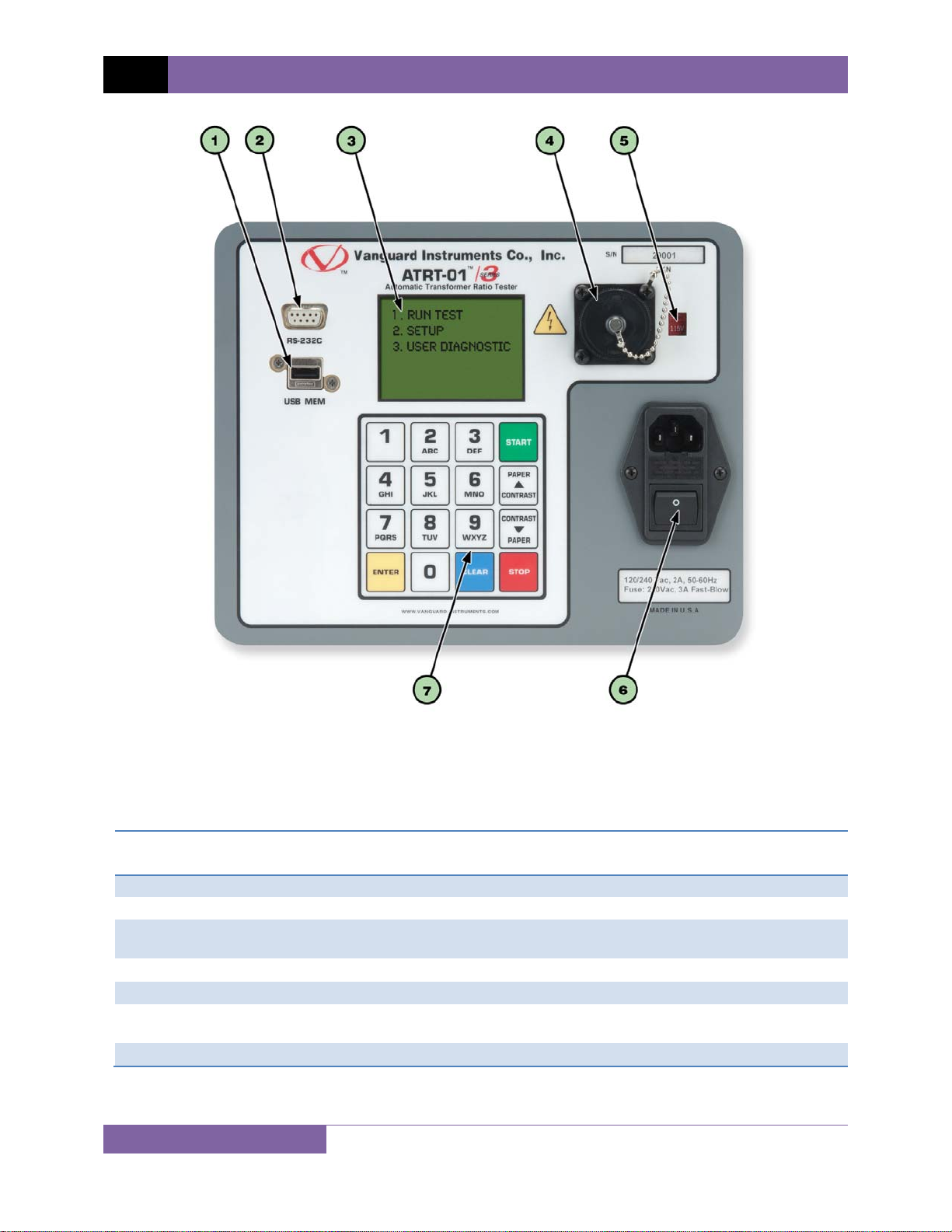
Figure 1. ATRT-01 S3 Controls and Indicators ................................................................................ 7
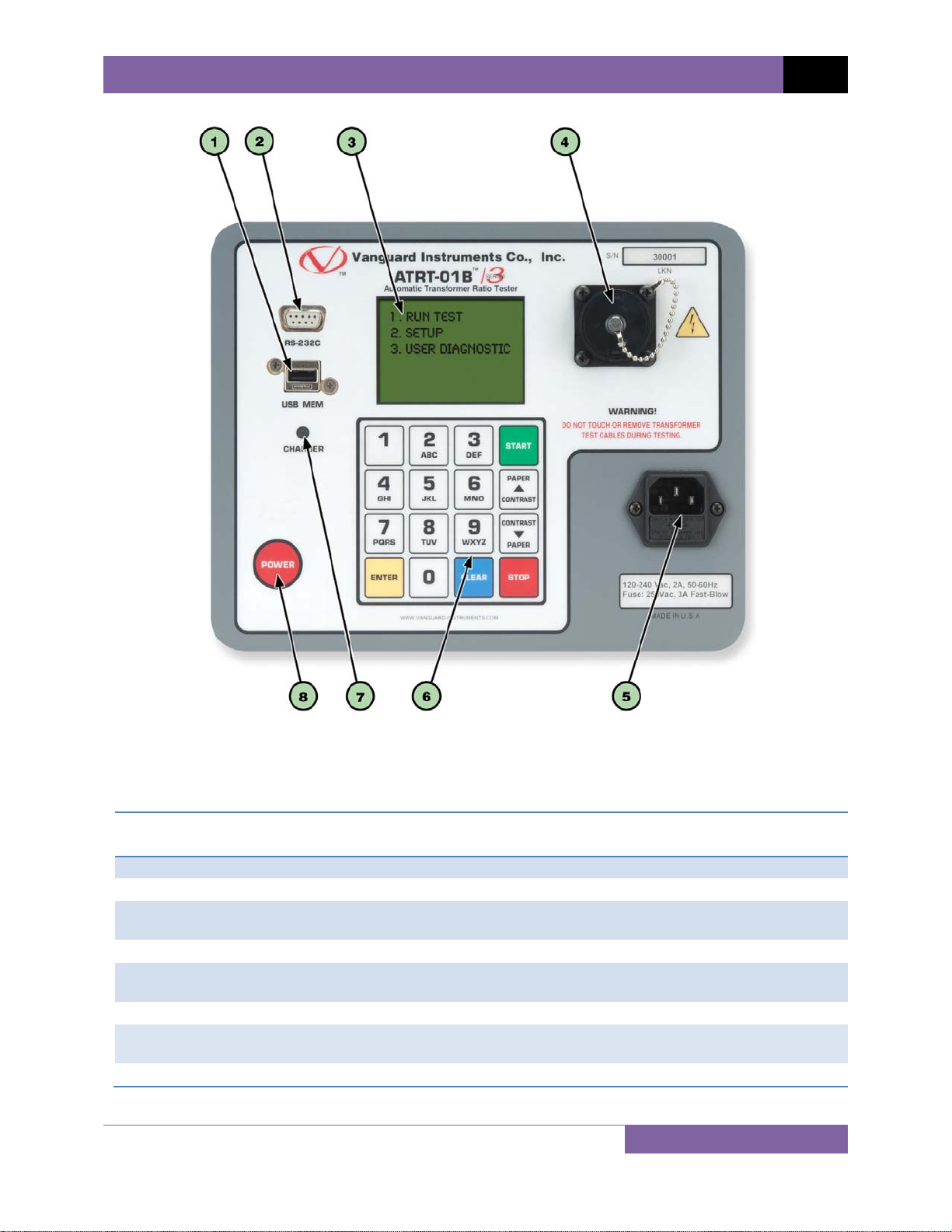
Figure 2. ATRT-01B S3 Controls and Indicators .............................................................................. 8
Figure 3. Typical Single-Phase Transformer Connection .............................................................. 10
Figure 4. Typical Auto Transformer Connection ........................................................................... 11
Figure 5. Typical CT Connection .................................................................................................... 12
Figure 6. Typical Bushing CT Connection on a Single Transformer .............................................. 13
iii
Page 5
REV 1 ATRT-01/01B S3 USER’S MANUAL
CONVENTIONS USED IN THIS DOCUMENT
This document uses the following conventions:
• The general term “ATRT” is used in this manual to refer to the ATRT-01 S3 and ATRT-01B S3.
A key, switch, or knob on the ATRT is indicated as [KEY], [SWITCH], [KNOB].
•
Menu names are referenced as “MENU NAME”
•
• ATRT screen output is shown as:
1. OPTION 1
2. OPTION 2
3. OPTION 3
4. OPTION 4
5. OPTION 5
• When instructions are provided, the menu item that should be selected is outlined with a
rectangle as shown below (option 3 should be selected):
1. OPTION 1
2. OPTION 2
3. OPTION 3
4. OPTION 4
5. OPTION 5
• Warning messages are indicated as:
Warning message
WARNING
• Important notes are indicated as:
Note details
NOTE
1
Page 6

ATRT-01/01B S3 USER’S MANUAL REV 1
1.0 INTRODUCTION
1.1 General Description and Features
The ATRT-01 S3 is Vanguard’s fourth generation, micro-processor based, single phase,
automatic transformer turns-ratio tester. This portable test unit is available in two models, the
ATRT-01 S3 (line power only), and the ATRT-01B S3 (rechargeable-battery powered).
The ATRT-01 S3 uses the IEEE C57.12.90 measuring method to determine the transformer
turns-ratio. The transformer turns-ratio is determined by precisely measuring the voltages
across the unloaded transformer windings. The ATRT-01 S3’s measuring circuitry self adjusts
before each measurement to ensure turns-ratio accuracy. Two selectable test voltages, 4Vac
and 40Vac, offer flexibility in testing different types of transformers.
The ATR-01 S3 can measure turns-ratios ranging from 0.8 to 15,000 and can be used to test
voltage regulators, power transformers, current transformers (CT), and potential transformers
(PT). The ATRT-01 S3 also measures and displays transformer-winding excitation current,
winding polarity, and winding phase angle. Test results are displayed on a back-lit LCD screen
(128 x 64 pixels) that is viewable in bright sunlight and low-light conditions.
In addition to measuring a transformer’s turns-ratio, the transformer’s name plate voltages can
also be entered, and the ATRT-01 S3 will then display the turns-ratio percentage error. This
convenient feature eliminates any user-calculation errors when testing transformers.
When testing a 3-phase transformer, the ATRT-01 S3 provides connection information (H and X
test leads to the transformer bushings) for phase A, B and C tests. The three phase test results
(turns-ratio, excitation current, winding polarity, phase-angle, and percentage error) are
displayed on the LCD screen.
User Interface
The ATRT-01 S3 features a back-lit LCD screen (128 x 64 pixels) that is viewable in direct sunlight
and low-light levels. A rugged 16-key membrane keypad is used to enter test information and to
operate the unit.
Test Record Storage
The ATRT-01 S3 can store 128 records of 33 readings internally, and up to 999 test records on
an external USB Flash drive. Test records can be recalled using the included Transformer
Analysis PC software.
Computer Interface
A Windows®-based (XP/Vista/7) Transformer Analysis Software is provided with each unit and
can be used to remotely control the ATRT-01 S3 via the RS-232C port. Using the Transformer
Analysis software, the user can retrieve test records (from the ATRT-01 S3’s memory or a USB
Flash drive), analyze test results, and print test results on a desktop printer. Test results are
automatically exported to PDF, Excel, and XML formats.
2
Page 7

REV 1 ATRT-01/01B S3 USER’S MANUAL
Battery Power for Exceptional Portability
The ATRT-01B S3 is powered by a 6-volt, 7 ampere-hour, lead acid battery. This high capacity
battery, coupled with the ATRT-01B S3’s low power consuming circuitry, allows the unit to be
used continuously for up to 4 hours per charge. A built-in charger allows the unit to be used
during charging.
3
Page 8

ATRT-01/01B S3 USER’S MANUAL REV 1
1.2 Technical Specifications
1.2.1. ATRT-01 S3 Technical Specifications
Table 1. ATRT-01 S3 Technical Specifications
TYPE Transformer Turns Ratio Tester
PHYSICAL SPECIFICATIONS Dimensions: 12” x 10” x 8” (30.4 cm x 25.4 cm x 20.3 cm)
Weight: 8 lbs (3.6 Kg)
INPUT POWER 120 or 240 Vac (Selectable), 50/60 Hz
MEASURING METHOD ANSI/IEEE C57.12.90
RATIO MEASURING RANGE 0.8 - 15,000 (5 digit resolution)
TURNS-RATIO ACCURACY 40 Vac: 0.8-1,999 (0.1%), 2,000-3,999 (0.25%), 4,000-15,000 (1%)
4 Vac: 0.8-1,999 (0.1%), 2,000-3,999 (0.25%), 4,000-15,000 (2%)
TEST VOLTAGE 4 Vac @ 1.0A, 40 Vac @ 0.6A
PHASE ANGLE
MEASUREMENT
POLARITY READING In-Phase or Out-of-Phase indication
EXCITATION CURRENT
READING RANGE
DISPLAY Back-lit LCD (128 x 64 pixels), viewable in direct sunlight and lo w light levels
COMPUTER INTERFACE RS-232C
PC SOFTWARE Windows XP/Vista/7 Transformer Analysis Software (included with purchase)
INTERNAL TEST RECORD
STORAGE
EXTERNAL TEST RECORD
STORAGE
SAFETY Designed to meet IEC 61010 (1995), UL 61010A-1, and CSA-C22.2
ENVIRONMENT Operating: -10ºC to 50ºC (15ºF to +122ºF)
HUMIDITY (MAX) 90% RH @ 40˚ C (104˚ F) non-condensing
ALTITUDE (MAX) 2000m (6562 ft) to full safety specifications
CABLES One 15 ft. (4.6m) Single phase cable, one power cord, one cable bag
OPTIONS Transportation Case (Can hold unit and cables)
WARRANTY One year on parts and labor
0 - 360 degrees, Accuracy ±0.2 degree (±1 digit)
0-2 Amperes, Accuracy: 2% of reading (±1 mA)
128 records of 33 readings
Up to 999 test records on external USB Flash drive.
standards
Storage: (-30ºC to 70ºC (-22ºF to +158ºF)
The above specifications are valid at nominal operating voltage and at a
temperature of 25°C (77°F). Specifications may change without prior notice.
NOTE
4
Page 9

REV 1 ATRT-01/01B S3 USER’S MANUAL
1.2.2. ATRT-01B S3 Technical Specifications
Table 2. ATRT-01B S3 Technical Specifications
TYPE Transformer Turns Ratio Tester
PHYSICAL SPECIFICATIONS Dimensions: 12” x 10” x 8” (30.4 cm x 25.4 cm x 20.3 cm)
Weight: 9 lbs (4.3 Kg)
INPUT POWER 90 to 240 Vac, 50/60 Hz
Battery: SLA battery delivering up to 4 hours of continuous operation per
charge.
MEASURING METHOD ANSI/IEEE C57.12.90
RATIO MEASURING RANGE 0.8 - 15,000 (5 digit resolution)
TURNS-RATIO ACCURACY 40 Vac: 0.8-1,999 (0.1%), 2,000-3,999 (0.25%), 4,000-15,000 (1%)
4 Vac: 0.8-1,999 (0.1%), 2,000-3,999 (0.25%), 4,000-15,000 (2%)
TEST VOLTAGE 4 Vac @ 500mA, 40 Vac @ 70mA
PHASE ANGLE
MEASUREMENT
POLARITY READING In-Phase or Out-of-Phase indication
EXCITATION CURRENT
READING RANGE
DISPLAY Back-lit LCD (128 x 64 pixels), viewable in direct sunlight and lo w light levels
COMPUTER INTERFACE RS-232C
PC SOFTWARE Windows XP/Vista/7 Transformer Analysis Software (included with purchase)
INTERNAL TEST RECORD
STORAGE
EXTERNAL TEST RECORD
STORAGE
SAFETY Designed to meet IEC 61010 (1995), UL 61010A-1, and CSA-C22.2
ENVIRONMENT Operating: -10ºC to 50ºC (15ºF to +122ºF)
HUMIDITY (MAX) 90% RH @ 40˚ C (104˚ F) non-condensing
ALTITUDE (MAX) 2000m (6562 ft) to full safety specifications
CABLES One 15 ft. (4.6m) Single phase cable, one power cord, one cable bag
OPTIONS Transportation Case (Can hold unit and cables)
WARRANTY One year on parts and labor
0 - 360 degrees, Accuracy ±0.2 degree (±1 digit)
0-2 Amperes, Accuracy: 2% of reading (±1 mA)
128 records of 33 readings
Up to 999 test records on external USB Flash drive.
standards
Storage: (-30ºC to 70ºC (-22ºF to +158ºF)
The above specifications are valid at nominal operating voltage and at a
temperature of 25°C (77°F). Specifications may change without prior notice.
NOTE
5
Page 10

ATRT-01/01B S3 USER’S MANUAL REV 1
1.2.3. Controls and Indicators
The ATRT-01 S3 and ATRT-01B S3 controls and indicators are shown in Figure 1 and Figure 2,
respectively. A leader line with an index number points to each control and indicator, which is
cross-referenced to a functional description in the corresponding table. The purpose of the
controls and indicators may seem obvious, but users should familiarize themselves with them
before using the ATRT. Accidental misuse of the controls will usually cause no serious harm.
Users should also familiarize themselves with the safety summary information found on the
front page of this User’s Manual.
6
Page 11
REV 1 ATRT-01/01B S3 USER’S MANUAL
Table 3. Functional Descriptions of ATRT-01 S3 Controls and Indicators
Item
Number
1
2
3
4
5
6
7
Panel Markings Functional Description
120/240 Vac, 2A, 50-60Hz
Fuse: 250Vac, 3A Fast-Blow
7
Figure 1. ATRT-01 S3 Controls and Indicators
USB MEM USB Flash drive interface
RS-232C RS-232C computer interface port
H and X lead connector (16-pin male).
Voltage selection switch
Rugged alpha-numeric keypad
Back-lit LCD screen (128 x 64 pixels), viewable in direct sunlight and low
light levels
Input power connector and fused power sw itch w ith third-w ire sa fe ty
ground.
Page 12
ATRT-01/01B S3 USER’S MANUAL REV 1
Item
Number
1
2
3
4
5
6
7
8
Figure 2. ATRT-01B S3 Controls and Indicators
Table 4. Functional Descriptions of ATRT-01B S3 Controls and Indicators
Panel Markings Functional Description
USB MEM USB Flash drive interface
RS-232C RS-232C computer interface port
H and X lead connector (16-pin male).
120-240 Vac, 2A, 50-60Hz
Fuse: 250Vac, 3A Fast-Blow
Rugged alpha-numeric keypad
CHARGER
POWER Power switch
Back-lit LCD screen (128 x 64 pixels), viewable in bright sunlight and
low light levels
Input power connector
Battery charging indicator. LED lights up when bat tery is being
charged.
8
Page 13

REV 1 ATRT-01/01B S3 USER’S MANUAL
2.0 PRE-TEST SETUP
2.1 ATRT-01 S3 Operating Voltage
The ATRT-01 S3 can be operated from 120 Vac or 240 Vac. The power voltage can be set using
the voltage selector switch on the front panel (see Figure 1, item #5)
2.2 ATRT-01B S3 Operating Power
The ATRT-01B S3 is powered by a rechargeable (6 Vdc / 7 AH) sealed lead acid gel battery. The
unit can operate continuously for up to 6 hours between charges. It can also be used while
charging. Plugging the ATRT-01B S3 into an ac power outlet after the battery is fully charged will
not damage the battery.
• It is recommended that the ATRT-01B S3 be plugged into an ac outlet when it is
NOTES
2.3 LCD Screen Contrast Control
not in use.
• The ATRT-01B S3 uses the Genesis model NP7-6 battery. It can also be replaced
with the Panasonic model LC-R122R2PU battery.
To increase the LCD screen contrast, press and hold the [∧ Contrast] key for two seconds.
Release the button when the desired contrast level has been reached.
To decrease the LCD screen contrast, press and hold the [∨ Contrast] key for two seconds.
Release the button when the desired contrast level has been reached.
For the ATRT-01B S3, the back-light turns off after 30 seconds of operation to conserve power.
Press any key on the keypad to re-light the back-light.
9
Page 14
ATRT-01/01B S3 USER’S MANUAL REV 1
3.0 OPERATING PROCEDURES
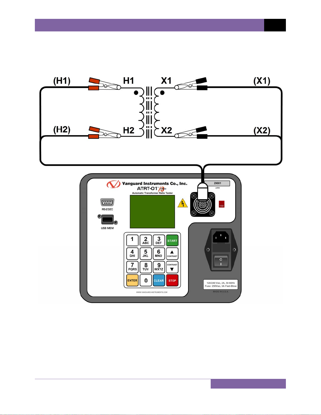
3.1 ATRT Transformer Connection Diagrams
Figure 3. Typical Single-Phase Transformer Connection
10
Page 15
REV 1 ATRT-01/01B S3 USER’S MANUAL
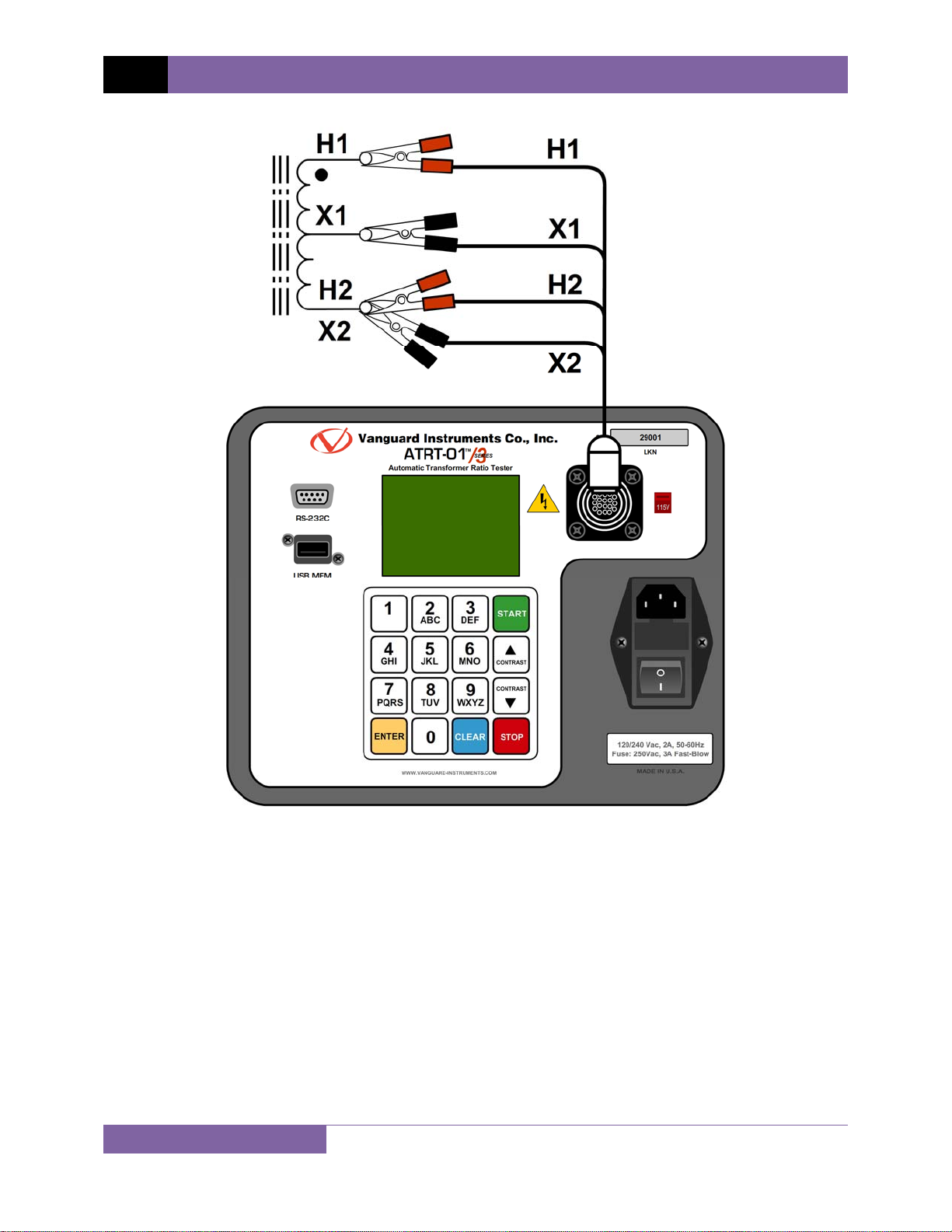
11
Figure 4. Typical Auto Transformer Connection
Page 16
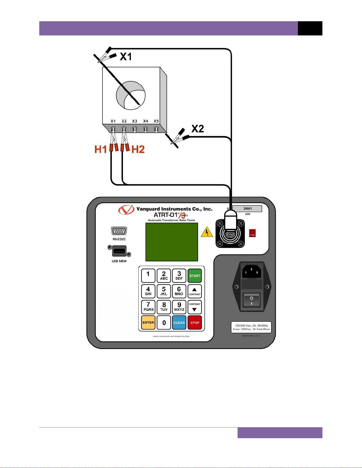
ATRT-01/01B S3 USER’S MANUAL REV 1
Figure 5. Typical CT Connection
12
Page 17
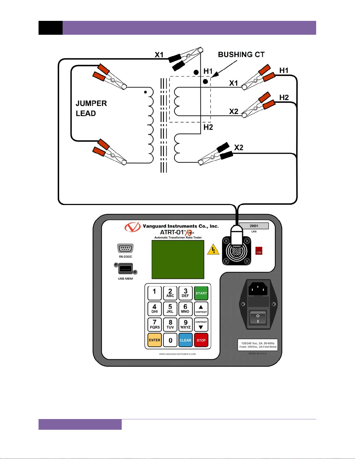
REV 1 ATRT-01/01B S3 USER’S MANUAL
Figure 6. Typical Bushing CT Connection on a Single Transformer
13
Page 18

ATRT-01/01B S3 USER’S MANUAL REV 1
3.2 Setting the Test Voltage
The ATRT offers two test voltages, 4 Vac and 40 Vac. The unit always defaults to 40 Vac at
power-on. The 4 Vac test voltage can be used in situations where the 40 Vac excitation voltage
may saturate the CT’s. To set the test voltage:
a. Turn on the unit and start from the “ START-UP” menu:
1. TEST TRANSFORMER
2. SETUP
3. CALCULATOR
time: 14:21:34
date: 05/24/11
1. TEST TRANSFORMER
2. SETUP
3. CALCULATOR
bAT:
time: 14:21:34
date: 05/24/11
ATRT-01 S3 “START-UP” menu ATRT-01B S3 “START-UP” menu
Press the [2] key (SETUP).
b. The following screen will be displayed:
1. RECORD ID
2. TEST VOLTAGE
3. PRINT RECORD
4. SAVE/RESTORE RECORD
5. SET TIME
6. SET LANGUAGE
1. RECORD ID
2. TEST VOLTAGE
3. PRINT RECORD
4. SAVE/RESTORE RECORD
5. SET TIME
6. SET LANGUAGE
7. SET 50/60 HZ
ATRT-01 S3 ATRT-01B S3
Press the [2] key (TEST VOLTAGE).
c. The following screen will be displayed:
1. 4 Volts
2. 40 VOLTS
Press the [1] key (4 VOLTS) to select 4 volts as the test voltage or press the [2] key (40
VOLTS) to select 40 volts as the test voltage.
14
Page 19

REV 1 ATRT-01/01B S3 USER’S MANUAL
d. The voltage will be set and the following confirmation message will be displayed:
40 VOLTS SET
Press any key to return to the “START-UP” menu.
15
Page 20

3.3 Setting the Date and Time
To set the date and time:
a. Start from the “START-UP” menu:
1. TEST TRANSFORMER
2. SETUP
3. CALCULATOR
time: 14:21:34
date: 05/24/11
Press the [2] key (SETUP).
b. The following screen will be displayed:
1. RECORD ID
2. TEST VOLTAGE
3. PRINT RECORD
4. SAVE/RESTORE RECORD
5. SET TIME
6. SET LANGUAGE
ATRT-01/01B S3 USER’S MANUAL REV 1
Press the [5] key (SET TIME)
c. The following screen will be displayed:
ENTER DATE
MM-DD-YY
Type in the date using the alpha-numeric keypad. The following screen will be displayed:
ENTER TIME
HH:MM:SS
Enter the time using the alpha-numeric keypad. When the time has been entered, you
will be immediately returned to the “START-UP” menu.
16
Page 21

REV 1 ATRT-01/01B S3 USER’S MANUAL
3.4 Setting the Interface Language
Follow the steps below to set the interface language (English, Spanish, or Turkish):
a. Start from the “START-UP” menu:
1. TEST TRANSFORMER
2. SETUP
3. CALCULATOR
time: 14:21:34
date: 05/24/11
Press the [2] key (SETUP).
b. The following screen will be displayed:
1. RECORD ID
2. TEST VOLTAGE
3. PRINT RECORD
4. SAVE/RESTORE RECORD
5. SET TIME
6. SET LANGUAGE
Press the [6] key (SET LANGUAGE).
c. The following screen will be displayed:
1. ENGLISH
2. TURKISH
3. SPANISH
Select the preferred interface language by pressing the corresponding key on the
keypad (
[1], [2], or [3]). The interface language will be set and a confirmation screen
will be displayed as shown below:
ENGLISH SET
Press any key to return to the “START-UP” menu.
17
Page 22
ATRT-01/01B S3 USER’S MANUAL REV 1
3.5 Setting the Frequency (ATRT-01B S3 Only)
Follow the steps below to set the preferred frequency (50 or 60 Hz):
a. Start from the “START-UP” menu:
1. TEST TRANSFORMER
2. SETUP
3. CALCULATOR
bAT:
time: 14:21:34
date: 05/24/11
Press the [2] key (SETUP).
b. The following screen will be displayed:
1. RECORD ID
2. TEST VOLTAGE
3. PRINT RECORD
4. SAVE/RESTORE RECORD
5. SET TIME
6. SET LANGUAGE
7. SET 50/60 HZ
Press the [7] key (SET 50/60 HZ).
c. The following screen will be displayed:
1. 60 Hz
2. 50 hz
Select the preferred frequency by pressing the corresponding key on the keypad (
[2]). The frequency will be set and a confirmation screen will be displayed as shown
below:
60 hz set
[1] or
Press any key to return to the “START-UP” menu.
18
Page 23

REV 1 ATRT-01/01B S3 USER’S MANUAL
3.6 Performing Tests
3.6.1. Entering Test Record Header Information
You can enter the test record header information before performing tests. The record header
includes identifying information such as the company, station, circuit, manufacturer, etc. Once
the header information has been set, it will apply to all subsequent test records. Follow the
steps below to enter the test header information:
a. Start from the “START-UP” menu:
1. TEST TRANSFORMER
2. SETUP
3. CALCULATOR
time: 14:21:34
date: 05/24/11
Press the [2] key (SETUP).
b. The following screen will be displayed:
1. RECORD ID
2. TEST VOLTAGE
3. PRINT RECORD
4. SAVE/RESTORE RECORD
5. SET TIME
6. SET LANGUAGE
Press the [1] key (RECORD ID).
c. The following screen will be displayed:
COMPANY:
_
↑/↓ TO POSITION
"ENTER" TO ACCEPT
Type the company name using the alpha-numeric keypad.
When pressing a key, the corresponding number on the key will be displayed first.
Pressing the key again will display the first letter on the key. Pressing the key again will
display the second letter on the key. For example, to type the letter “A”, you must press
[2] key twice. To erase the character at the cursor position, press the [CLEAR] key.
the
Press the
[Contrast ∧] key to move to the next character. Press the [Contrast ∨]
key to move to the previous character. Press the [ENTER] key when you are done
typing the company name.
19
Page 24

d. The following screen will be displayed:
STATION:
_
↑/↓ TO POSITION
"ENTER" TO ACCEPT
Type the station name using the alpha-numeric keypad and then press the [ENTER]
key.
e. The following screen will be displayed:
CIRCUIT:
_
↑/↓ TO POSITION
"ENTER" TO ACCEPT
ATRT-01/01B S3 USER’S MANUAL REV 1
Type the circuit information using the alpha-numeric keypad and then press the
[ENTER] key.
f. The following screen will be displayed:
MANUFACTURER:
_
↑/↓ TO POSITION
"ENTER" TO ACCEPT
Type the manufacturer name using the alpha-numeric keypad and then press the
[ENTER] key.
20
Page 25

REV 1 ATRT-01/01B S3 USER’S MANUAL
g. The following screen will be displayed:
MODEL:
_
↑/↓ TO POSITION
"ENTER" TO ACCEPT
Type the transformer’s model information using the alpha-numeric keypad and then
press the [ENTER] key.
h. The following screen will be displayed:
SERIAL NUMBER:
_
↑/↓ TO POSITION
"ENTER" TO ACCEPT
Type the transformer’s serial number using the alpha-numeric keypad and then press
the [ENTER] key.
i. The following screen will be displayed:
KVA RATING:
_
↑/↓ TO POSITION
"ENTER" TO ACCEPT
Type the transformer’s KVA rating using the alpha-numeric keypad and then press the
[ENTER] key.
21
Page 26

j. The following screen will be displayed:
OPERATOR:
_
↑/↓ TO POSITION
"ENTER" TO ACCEPT
Type the operator’s name using the alpha-numeric keypad and then press the [ENTER]
key. All header information will be saved, and you will be returned to the “START-UP”
menu.
ATRT-01/01B S3 USER’S MANUAL REV 1
22
Page 27

REV 1 ATRT-01/01B S3 USER’S MANUAL
3.6.2. Testing a Single Phase Transformer
Follow the steps below to test a single phase transformer:
a. Start from the “START-UP” menu:
1. TEST TRANSFORMER
2. SETUP
3. CALCULATOR
time: 14:21:34
date: 05/24/11
Press the [1] key (TEST TRANSFORMER).
b. The following screen will be displayed:
XFMR CONFIG:
1. SINGLE PHASE
2. Dy
3. YD
4. DD
5. YY
6. NEXT PAGE
Press the [1] key (SINGLE PHASE).
c. The following screen will be displayed:
NAME PLATE VOLTAGE?
1. yes
2. no
3. use prev data
Option 3 (USE PREV DATA) will be listed only if you had provided name plate
voltages for a previous test.
NOTE
1. YES
Press the [1] key (YES) if you would like to enter the transformer name plate
voltage values. The following screen will be displayed:
23
Page 28

ATRT-01/01B S3 USER’S MANUAL REV 1
NAME PLATE VOLTAGE:
H : X
0 :
Type the H winding name plate voltage value using the numeric keypad. The
screen will be updated as shown:
NAME PLATE VOLTAGE:
H : X
500 :
Press the [ENTER] key. The following screen will be displayed:
NAME PLATE VOLTAGE:
H : X
500 : 0
Type the X winding name plate voltage value using the numeric keypad. The
screen will be updated as shown:
NAME PLATE VOLTAGE:
H : X
500 : 10
Press the
[ENTER] key. Continue to step d.
2. NO
Press the [2] key (NO) if you do not want to enter the transformer name plate
voltage. Continue to step d.
3. USE PREV DATA
Press the
[3] key (USE PREV DATA) to use the name plate voltage values entered
when performing the last test. Continue to step d.
24
Page 29

REV 1 ATRT-01/01B S3 USER’S MANUAL
d. The following screen will be displayed:
"START" TO TEST
OR
"STOP" TO ABORT
Press the
[START] key to start the test.
e. The following screen will be displayed while the test is being performed:
TESTING AT 40 VOLTS
TEST IN PROGRESS
PLEASE WAIT...
The test results will be displayed on the LCD screen when testing has finished:
RAT: +1.003
PHS: 0.02°
mA: 0.0
ERR: 0.05%
The percentage error (ERR) will be displayed only if name plate voltage values
were entered.
NOTE
The polarity is displayed as either a plus sign (+) for “in-phase” or a minus sign (-) for
“out-of-phase”.
Press any key to continue.
25
Page 30

f. The following screen will be displayed:
KEEP THIS READING?
1. YES
2. NO
Press the [1] key (YES) to save the reading.
g. The following screen will be displayed:
TEST SAVED
ATRT-01/01B S3 USER’S MANUAL REV 1
Press any key to continue.
The above screen will be displayed if there is currently no data in the unit’s
memory buffer. If a test was previously performed or a test record was
NOTE
restored from Flash EEPROM or from a Flash drive, the following screen will
be displayed instead:
PREVIOUS DATA IN BUF
1. APPEND PREV. DATA
2. CLEAR PREV. DATA
Press the [1] key (APPEND PREV. DATA) to append the data in the unit’s
working memory to the current test results, or press the [2] key (CLEAR PREV.
DATA) to clear any previous data from the unit’s memory buffer and only save
the current test results.
The following screen will then be displayed:
TEST SAVED
Press any key to continue.
26
Page 31

REV 1 ATRT-01/01B S3 USER’S MANUAL
h. The following screen will be displayed:
RUN ANOTHER TEST?
1. YES
2. NO
3. REPEAT PREV. TEST
Press the [2] key (NO).
i. The following screen will be displayed:
SAVE THIS RECORD?
1. YES
2. NO
Press the [1] key (YES) to save the test record to the unit’s Flash EEPROM.
j. The test record will be saved and the following screen will be displayed:
RECORD NUMBER 1
HAS BEEN SAVED!
The unit will automatically assign the record number and will not over-write
existing test records.
NOTE
Press any key to return to the “START-UP” menu.
27
Page 32

ATRT-01/01B S3 USER’S MANUAL REV 1
3.6.3. Testing a Three Phase Transformer
Follow the steps below to test a three phase transformer:
a. Start from the “START-UP” menu:
1. TEST TRANSFORMER
2. SETUP
3. CALCULATOR
time: 14:21:34
date: 05/24/11
Press the [1] key (TEST TRANSFORMER).
b. The following screen will be displayed:
XFMR CONFIG:
1. SINGLE PHASE
2. Dy
3. YD
4. DD
5. YY
6. NEXT PAGE
You can press the [6] key (NEXT PAGE) to view additional transformer types.
The following screen will be displayed:
NOTE
XFMR CONFIG:
1. DZ
2. ZD
3. YZ
4. ZY
5. TT
6. PREVIOUS PAGE
Select a three-phase transformer test by pressing the corresponding key ([2] to [5]). For
this example, press the
[2] key (Dy) from the first page to select the Delta to Y phase
transformer test.
c. The following screen will be displayed:
X0 ACCESSIBLE?
1. YES
2. NO
Press the
[1] key (YES) if X0 is accessible or the [2] key (NO) if it is not accessible.
28
Page 33

REV 1 ATRT-01/01B S3 USER’S MANUAL
d. The following screen will be displayed:
1. DY1
2. DY3
3. DY5
4. DY7
5. DY9
6. DY11
Select the transformer configuration by pressing the corresponding key ([1] to [6]). For
this example, press the [1] key (Dy1).
e. The following screen will be displayed:
NAME PLATE VOLTAGE?
1. yes
2. no
3. USE PREV DATA
Option 3 (USE PREV DATA) will be listed only if you had provided name plate
voltages for a previous test.
NOTE
1. YES
Press the [1] key (YES) if you would like to enter the transformer name plate
voltage values. The following screen will be displayed:
NAME PLATE VOLTAGE:
H : X
0 :
Type the H winding name plate voltage value using the numeric keypad. The
screen will be updated as shown:
NAME PLATE VOLTAGE:
H : X
500 :
Press the [ENTER] key. The following screen will be displayed:
29
Page 34

ATRT-01/01B S3 USER’S MANUAL REV 1
NAME PLATE VOLTAGE:
H : X
500 : 0
Type the X winding name plate voltage value using the numeric keypad. The
screen will be updated as shown:
NAME PLATE VOLTAGE:
H : X
500 : 10
Press the [ENTER] key. Continue to step f.
2. NO
Press the [2] key (NO) if you do not want to enter the transformer name plate
voltage. Continue to step f.
3. USE PREV DATA
Press the [3] key (USE PREV DATA) to use the name plate voltage values entered
when performing the last test. Continue to step f.
f. The following screen will be displayed momentarily:
TESTING AT 40 VOLTS
Then the following screen will be displayed showing the Phase A cable connections for
the selected test (this will differ depending on the test selected):
PHASE A
CABLE
X1,X2 to x1,x0
h1,h2 to h1,h3
XFMR
"START" when READY
30
Page 35

REV 1 ATRT-01/01B S3 USER’S MANUAL
Make the cable connections per the instructions and then press the [START] key to
run the Phase A test.
g. The following screen will be displayed while the test is being performed:
TESTING:
DYN1 phase a
The Phase A test results will be displayed on the LCD screen when testing has finished:
RATIO MA %DIFF
+15.003 001 0.02
"ENTER" TO CONTINUE..
Press the [ENTER] key to continue.
h. The following screen will be displayed showing the Phase B cable connections for the
selected test:
PHASE B
CABLE
X1,X2 to x2,x0
h1,h2 to h2,h1
XFMR
"START" when READY
Make the cable connections per the instructions and then press the
[START] key to
run the Phase B test.
i. The following screen will be displayed while the test is being performed:
TESTING:
DYN1 phase B
The Phase A and B test results will be displayed on the LCD screen when testing has
finished:
31
Page 36

ATRT-01/01B S3 USER’S MANUAL REV 1
RATIO MA %DIFF
+15.003 001 0.02
+15.015 001 0.10
"ENTER" TO CONTINUE..
Line 1 of the results shows the Phase A test results, and line 2 shows the Phase B test
results.
Press the [ENTER] key to continue.
j. The following screen will be displayed showing the Phase C cable connections for the
selected test:
PHASE C
CABLE
X1,X2 to x3,x0
h1,h2 to h3,h2
XFMR
"START" when READY
Make the cable connections per the instructions and then press the [START] key to
run the Phase C test.
k. The following screen will be displayed while the test is being performed:
TESTING:
DYN1 phase C
The Phase A, B, and C test results will be displayed on the LCD screen when testing has
finished:
TEST RESULTS:
RATIO MA %DIFF
A +15.003 001 0.02
B +15.015 001 0.10
C +15.000 001 0.00
181.4° 183.2° 181.8°
XFMR TYPE: DYN1
The phase angles for Phase A, B, and C are also displayed at the bottom of the test
results from left to right, respectively. Press any key to continue.
32
Page 37

REV 1 ATRT-01/01B S3 USER’S MANUAL
l. The following screen will be displayed:
KEEP THIS READING?
1. YES
2. NO
Press the [1] key (YES) to save the reading.
m. The following screen will be displayed:
TEST SAVED
Press any key to continue.
The above screen will be displayed if there is currently no data in the unit’s
memory buffer. If a test was previously performed or a test record was
NOTE
restored from Flash EEPROM or from a Flash drive, the following screen will
be displayed instead:
PREVIOUS DATA IN BUF
1. APPEND PREV. DATA
2. CLEAR PREV. DATA
Press the [1] key (APPEND PREV. DATA) to append the data in the unit’s
working memory to the current test results, or press the [2] key (CLEAR PREV.
DATA) to clear any previous data from the unit’s memory buffer and only save
the current test results.
The following screen will then be displayed:
TEST SAVED
Press any key to continue.
33
Page 38

n. The following screen will be displayed:
RUN ANOTHER TEST?
1. YES
2. NO
3. REPEAT PREV. TEST
Press the [2] key (NO).
o. The following screen will be displayed:
SAVE THIS RECORD?
1. YES
2. NO
ATRT-01/01B S3 USER’S MANUAL REV 1
Press the [1] key (YES) to save the test record to the unit’s Flash EEPROM.
p. The test record will be saved and the following screen will be displayed:
RECORD NUMBER 2
HAS BEEN SAVED!
The unit will automatically assign the record number and will not over-write
existing test records.
NOTE
Press any key to return to the “START-UP” menu.
34
Page 39

REV 1 ATRT-01/01B S3 USER’S MANUAL
3.7 Working With Test Records
3.7.1. Viewing the Contents of the Working Memory
Whenever a test is performed or a test record is retrieved, the data is stored in the ATRT’s
working memory. You can view the test data using the steps below:
a. Start from the “START-UP” menu:
1. TEST TRANSFORMER
2. SETUP
3. CALCULATOR
time: 14:21:34
date: 05/24/11
Press the [2] key (SETUP).
b. The following screen will be displayed:
1. RECORD ID
2. TEST VOLTAGE
3. PRINT RECORD
4. SAVE/RESTORE RECORD
5. SET TIME
6. SET LANGUAGE
Press the [3] key (PRINT RECORD).
c. The basic test record information will be displayed as shown:
SINGLE PHASE
Num Tests: 1
05/26/11 15:33:58
Press the
1 SINGLE PHASE
40 volts
RATIO ma %DIFF
1.003 0002 0.3
[Contrast ∨] key. The test record details will be displayed as shown below:
Press the [STOP] key to return to the “START-UP” menu.
35
Page 40

ATRT-01/01B S3 USER’S MANUAL REV 1
3.7.2. Saving Test Results to a Test Record
After performing a test, the user is presented the option to save the test results to the unit’s
Flash EEPROM or to a USB Flash Drive. If the test results are not saved immediately after
performing a test, they will still remain in the working memory and can be saved later, as long
as a new test has not been performed and the unit has not been turned off. Follow the steps
below to save the test results from the working memory to a test record (the following
procedure can also be used to re-save a restored test record to a new memory location or to a
USB Flash Drive):
a. Perform a test or restore a test record to the working memory (see section 3.7.3 and
3.7.4), and then start from the “START-UP” menu:
1. TEST TRANSFORMER
2. SETUP
3. CALCULATOR
time: 14:21:34
date: 05/24/11
Press the [2] key (SETUP).
b. The following screen will be displayed:
1. RECORD ID
2. TEST VOLTAGE
3. PRINT RECORD
4. SAVE/RESTORE RECORD
5. SET TIME
6. SET LANGUAGE
Press the
[4] key (SAVE/RESTORE RECORD)
c. The following screen will be displayed:
1. RESTORE RECORD
2. SAVE RECORD
3. RECORD DIRECTORY
4. ERASE RECORD
5. COPY to THUMB DRIVE
Option 5 (COPY TO THUMB DRIVE) will be listed only if a USB Flash drive is
connected to the ATRT.
NOTE
Press the [2] key (SAVE RECORD).
36
Page 41

REV 1 ATRT-01/01B S3 USER’S MANUAL
If a USB Flash drive is connected to the unit, continue to step d.
If a USB Flash drive is NOT connected to the unit, continue to step e.
d. The following screen will be displayed:
1. SAVE INTERNALLY
2. SAVE TO THUMB DRIVE
1. SAVE INTERNALLY
Press the
[1] key (SAVE INTERNALLY) to save the test record to the unit’s Flash
EEPROM. Continue to step e.
2. SAVE TO THUMB DRIVE
Press the
[2] key (SAVE TO THUMB DRIVE) to save the test record to the
connected USB Flash drive. The following screen will be displayed:
REC_001 SAVED TO
THUMB DRIVE.
Press any key to return to the “START-UP” menu.
e. The following screen will be displayed:
RECORD NUMBER 2
HAS BEEN SAVED!
Press any key to return to the “START-UP” menu.
37
Page 42

ATRT-01/01B S3 USER’S MANUAL REV 1
3.7.3. Restoring a Test Record From Flash EEPROM
Use the steps below to restore a test record from the ATRT’s Flash EEPROM to the working
memory:
a. Start from the “START-UP” menu:
1. TEST TRANSFORMER
2. SETUP
3. CALCULATOR
time: 14:21:34
date: 05/24/11
Press the [2] key (SETUP).
b. The following screen will be displayed:
1. RECORD ID
2. TEST VOLTAGE
3. PRINT RECORD
4. SAVE/RESTORE RECORD
5. SET TIME
6. SET LANGUAGE
Press the [4] key (SAVE/RESTORE RECORD).
c. The following screen will be displayed:
1. RESTORE RECORD
2. SAVE RECORD
3. RECORD DIRECTORY
4. ERASE RECORD
5. COPY to THUMB DRIVE
Option 5 (COPY TO THUMB DRIVE) will be listed only if a USB Flash drive is
connected to the ATRT.
NOTE
Press the [1] key (RESTORE RECORD).
38
Page 43

REV 1 ATRT-01/01B S3 USER’S MANUAL
d. The following screen will be displayed:
RESTORE RECORD
1.ENTER RECORD NUMBER
2.SCROLL TO SELECT
If you have a USB Flash drive inserted in the ATRT’s “USB MEM” port, the
following screen will be displayed instead of the above screen:
NOTE
1.INTERNAL STORAGE
2.THUMB DRIVE
Press the [1] key (INTERNAL STORAGE).
The following screen will be displayed:
RESTORE RECORD
1.ENTER RECORD NUMBER
2.SCROLL TO SELECT
Continue with the steps below.
1. ENTER RECORD NUMBER
Press the [1] key (ENTER RECORD NUMBER) if you know the record number that
you would like to restore.
1.1. The following screen will be displayed:
RESTORE RECORD
NUMBER:
39
Type the record number using the alpha-numeric keypad and then press
the
[ENTER] key.
Page 44

ATRT-01/01B S3 USER’S MANUAL REV 1
1.2. The following screen will be displayed:
RECORD RESTORED!
DISPLAY RECORD?
1.YES
2.NO
Press the [1] key (YES) to display the test record.
1.3. The basic information about the restored test record will be displayed as
shown:
SINGLE PHASE
Num Tests: 1
05/27/11 15:25:57
Press the [Contrast ∨] key. The test record details will be displayed as
shown:
1 SINGLE PHASE
40 volts
RATIO ma %DIFF
1.003 0002 0.3
Press the
[STOP] key to return to the “START-UP” menu. The restored
test record will remain loaded in the working memory.
2. SCROLL TO SELECT
Press the
[2] key (SCROLL TO SELECT) to scroll through a directory of the stored
test records.
2.1. The following screen will be displayed:
RECORDS DIRECTORY
"UP" TO SCROLL FWD
"DWN" TO SCROLL RVS
40
Page 45

REV 1 ATRT-01/01B S3 USER’S MANUAL
Press the [Contrast ∧] button or the [Contrast ∨] key to display the
next or previous test record, respectively.
The basic test record information will be displayed as shown:
#1 05/25/11 09:52
SINGLE PHASE
1 TESTS
When you have located the test record that you would like to restored,
press the [ENTER] key. Continue to step 1.2 on page 40.
41
Page 46

ATRT-01/01B S3 USER’S MANUAL REV 1
3.7.4. Restoring a Test Record From a USB Flash Drive
Use the steps below to restore a test record from a USB Flash drive to the ATRT’s working
memory:
a. Make sure the USB Flash drive containing the test record(s) is inserted in the ATRT’s USB
Flash drive port (“USB MEM” port). Then start from the “START-UP” menu:
1. TEST TRANSFORMER
2. SETUP
3. CALCULATOR
time: 14:21:34
date: 05/24/11
Press the [2] key (SETUP).
b. The following screen will be displayed:
1. RECORD ID
2. TEST VOLTAGE
3. PRINT RECORD
4. SAVE/RESTORE RECORD
5. SET TIME
6. SET LANGUAGE
Press the [4] key (SAVE/RESTORE RECORD)
c. The following screen will be displayed:
1. RESTORE RECORD
2. SAVE RECORD
3. RECORD DIRECTORY
4. ERASE RECORD
5. COPY to THUMB DRIVE
Press the [1] key (RESTORE RECORD).
42
Page 47

REV 1 ATRT-01/01B S3 USER’S MANUAL
d. The following screen will be displayed:
1.INTERNAL STORAGE
2.THUMB DRIVE
Press the [2] key (THUMB DRIVE).
e. The following screen will be displayed:
RESTORE THUMB DRIVE
REC_
Type the record number that you would like to restore using the alpha-numeric keypad
and then press the [ENTER] key.
f. The test record will be restored to the unit’s working memory and the following screen
will be displayed:
REC_000 restored!
DISPLAY RECORD?
1.YES
2.NO
Press the
[1] key (YES) to display the restored test record.
g. The basic information about the restored test record will be displayed as shown below:
SINGLE PHASE
Num Tests: 1
05/27/11 15:25:57
43
Page 48

ATRT-01/01B S3 USER’S MANUAL REV 1
Press the [Contrast ∨] key. The test record details will be displayed as shown below:
1 SINGLE PHASE
40 volts
RATIO ma %DIFF
1.003 0002 0.3
Press the [STOP] key to return to the “START-UP” menu. The restored test record will
remain loaded in the working memory.
44
Page 49

REV 1 ATRT-01/01B S3 USER’S MANUAL
3.7.5. Copying Test Records to a USB Flash Drive
Use the steps below to copy one or all test records from the unit’s Flash EEPROM to a
connected USB Flash drive:
a. Make sure a USB Flash drive is connected to the unit’s “USB MEM” port, and then start
from the “START-UP” menu:
1. TEST TRANSFORMER
2. SETUP
3. CALCULATOR
time: 14:21:34
date: 05/24/11
Press the [2] key (SETUP).
b. The following screen will be displayed:
1. RECORD ID
2. TEST VOLTAGE
3. PRINT RECORD
4. SAVE/RESTORE RECORD
5. SET TIME
6. SET LANGUAGE
Press the [4] key (SAVE/RESTORE RECORD).
c. The following screen will be displayed:
1. RESTORE RECORD
2. SAVE RECORD
3. RECORD DIRECTORY
4. ERASE RECORD
5. COPY to THUMB DRIVE
Press the [5] key (COPY TO THUMB DRIVE).
45
Page 50

d. The following screen will be displayed:
COPY REC TO THUMB DRV
1.COPY SINGLE RECORD
2.COPY ALL RECORDS
1. COPY SINGLE RECORD
Press the [1] key (COPY SINGLE RECORD) to copy a single test record from the
ATRT’s Flash EEPROM to the connected USB Flash drive. The following screen will
be displayed:
ENTER RECORD NUMBER
TO COPY TO FLASH DRV
NUMBER:
ATRT-01/01B S3 USER’S MANUAL REV 1
Type the record number using the alpha-numeric keypad and then press the
[ENTER] key. The test record will be copied to the USB Flash drive and the
following screen will be displayed:
REC_000 SAVED TO
THUMB DRIVE
Press any key to return to the “START-UP” menu.
46
Page 51

REV 1 ATRT-01/01B S3 USER’S MANUAL
2. COPY ALL RECORDS
Press the [2] key (COPY ALL RECORDS) to copy all test records from the ATRT’s
Flash EEPROM to the connected USB Flash drive. All test records will be copied
from the unit to the connected USB Flash drive. The following screen will be
displayed when the process is finished:
ALL RECORDS HAVE BEEN
TRANSFERRED TO THUMB
DRIVE!
Press any key to return to the “START-UP” menu.
47
Page 52

ATRT-01/01B S3 USER’S MANUAL REV 1
3.7.6. Viewing the Test Record Directory
Use the steps below to browse through a directory of the test records stored in the ATRT’s
Flash EEPROM memory:
a. Start from the “START-UP” menu:
1. TEST TRANSFORMER
2. SETUP
3. CALCULATOR
time: 14:21:34
date: 05/24/11
Press the [2] key (SETUP).
b. The following screen will be displayed:
1. RECORD ID
2. TEST VOLTAGE
3. PRINT RECORD
4. SAVE/RESTORE RECORD
5. SET TIME
6. SET LANGUAGE
Press the [4] key (SAVE/RESTORE RECORD).
c. The following screen will be displayed:
1. RESTORE RECORD
2. SAVE RECORD
3. RECORD DIRECTORY
4. ERASE RECORD
5. COPY to THUMB DRIVE
Option 5 (COPY TO THUMB DRIVE) is listed only if a USB Flash drive is
connected to the unit.
NOTE
Press the [3] key (RECORD DIRECTORY).
48
Page 53

REV 1 ATRT-01/01B S3 USER’S MANUAL
d. The following screen will be displayed:
RECORDS DIRECTORY
"UP" TO SCROLL FWD
"DWN" TO SCROLL RVS
Press the [Contrast ∧] or [Contrast ∨] key to scroll through the test record
directory. The test record header will be displayed as shown:
SINGLE PHASE
Num Tests: 1
05/27/11 15:25:57
You can continue to scroll through the record directory by pressing the [Contrast ∧]
and [Contrast ∨] keys. Press the [STOP] key to return to the “START-UP” menu.
49
Page 54

ATRT-01/01B S3 USER’S MANUAL REV 1
3.7.7. Erasing Test Records from the Flash EEPROM
Follow the steps below to erase test records from the Flash EEPROM
a. Start from the “START-UP” menu:
1. TEST TRANSFORMER
2. SETUP
3. CALCULATOR
time: 14:21:34
date: 05/24/11
Press the [2] key (SETUP).
b. The following screen will be displayed:
1. RECORD ID
2. TEST VOLTAGE
3. PRINT RECORD
4. SAVE/RESTORE RECORD
5. SET TIME
6. SET LANGUAGE
Press the [4] key (SAVE/RESTORE RECORD).
c. The following screen will be displayed:
1. RESTORE RECORD
2. SAVE RECORD
3. RECORD DIRECTORY
4. ERASE RECORD
5. COPY to THUMB DRIVE
Press the
[4] key (ERASE RECORD).
50
Page 55

REV 1 ATRT-01/01B S3 USER’S MANUAL
d. The following screen will be displayed:
ERASE RECORD
1.ERASE SINGLE REC.
2.ERASE ALL RECORDS
"STOP" TO EXIT
If you have a USB Flash drive inserted in the ATRT’s “USB MEM” port, the
following screen will be displayed instead of the above screen:
NOTE
1.ERASE INTERNAL REC
2.ERASE THUMB DRV REC
Press the [1] key (ERASE INTERNAL REC).
The following screen will be displayed:
ERASE RECORD
1.ERASE SINGLE REC.
2.ERASE ALL RECORDS
"STOP" TO EXIT
Continue with the steps below.
1. ERASE SINGLE REC.
Press the [1] key (ERASE SINGLE REC.) to erase a single test record from the unit’s
internal Flash EEPROM. The following screen will be displayed:
ERASE RECORD
1.ENTER RECORD NUMBER
2.SCROLL TO SELECT
1. ENTER RECORD NUMBER
Press the
you would like to erase. The following screen will be displayed:
51
[1] key (ENTER RECORD NUMBER) if you know the record number that
Page 56

ATRT-01/01B S3 USER’S MANUAL REV 1
ERASE RECORD
NUMBER:
You can cancel the process and return to the “START-UP” menu by
pressing the [STOP] key.
NOTE
Type the record number that you would like to erase using the alpha-numeric
keypad and then press the
[ENTER] key. If you do not know the test record
number, you can first view the test record directory using the instructions in
section 3.7.6.
The following screen will be displayed while the record is being erased:
ERASing record
PLEASE WAIT...
The following screen will be displayed when the test record has been completely
erased:
RECORD NUMBER 8
ERASED!
Press any key to continue. You will be returned to the beginning of step d.
52
Page 57

REV 1 ATRT-01/01B S3 USER’S MANUAL
2. SCROLL TO SELECT
Press the [2] key (SCROLL TO SELECT) to scroll through the test record directory
and locate the test record that you would like to erase. The following screen will
be displayed:
RECORDS DIRECTORY
"UP" TO SCROLL FWD
"DWN" TO SCROLL RVS
Press the
[Contrast ∧] or [Contrast ∨] key to scroll through the test record
directory. The test record header will be displayed as shown:
SINGLE PHASE
Num Tests: 1
05/27/11 15:25:57
You can continue to scroll through the record directory by pressing the
[Contrast ∧] and [Contrast ∨] keys. Once you have located the test record
you would like to erase, press the [ENTER] key. The selected test record will be
erased and the following screen will be displayed:
RECORD NUMBER 9
ERASED!
Press any key to continue. You will be returned to the beginning of step d.
53
Page 58

ATRT-01/01B S3 USER’S MANUAL REV 1
2. ERASE ALL RECORDS
Press the [2] key (ERASE ALL RECORDS) to erase all the test records from the unit’s
internal Flash EEPROM. The following warning screen will be displayed:
ERASE ALL RECORDS!
ARE YOU SURE?
"ENTER" To CONTINUE.
You can press the [STOP] key to cancel the process and return to the “START-UP”
menu.
Press the [ENTER] key to proceed with deleting all the test records from the unit’s
Flash EEPROM. The following screen will be displayed during the erasure process:
ERASing recordS
PLEASE WAIT...
The following screen will be displayed when all test records have been completely
erased:
RECORDS ERASED!
Press any key to return to the “START-UP” menu.
54
Page 59

REV 1 ATRT-01/01B S3 USER’S MANUAL
3.7.8. Erasing Test Records from a USB Flash Drive
Follow the steps below to erase test records from a USB Flash drive:
a. Make sure a USB Flash drive is connected to the unit’s “USB MEM” port, and then start
from the “START-UP” menu:
1. TEST TRANSFORMER
2. SETUP
3. CALCULATOR
time: 14:21:34
date: 05/24/11
Press the [2] key (SETUP).
b. The following screen will be displayed:
1. RECORD ID
2. TEST VOLTAGE
3. PRINT RECORD
4. SAVE/RESTORE RECORD
5. SET TIME
6. SET LANGUAGE
Press the [4] key (SAVE/RESTORE RECORD).
c. The following screen will be displayed:
1. RESTORE RECORD
2. SAVE RECORD
3. RECORD DIRECTORY
4. ERASE RECORD
5. COPY to THUMB DRIVE
Press the
[4] key (ERASE RECORD).
d. The following screen will be displayed:
1.ERASE INTERNAL REC
2.ERASE THUMB DRV REC
Press the [2] key (ERASE THUMB DRV REC).
55
Page 60

e. The following screen will be displayed:
ERASE RECORD
1.ERASE SINGLE REC.
2.ERASE ALL RECORDS
"STOP" TO EXIT
1. ERASE SINGLE REC.
Press the [1] key (ERASE SINGLE REC.) to erase a single test record from the
connected USB Flash drive. The following screen will be displayed:
ERASE THUMB DRIVE
REC_
ATRT-01/01B S3 USER’S MANUAL REV 1
Type the record number that you would like to erase using the alpha-numeric
keypad and then press the [ENTER] key. The test record will be erased from the
USB Flash drive and the following screen will be displayed:
THUMB DRIVE RE000
ERASED!
Press any key to continue. You will be returned to the beginning of step e. Press the
[STOP] key to return to the “START-UP” menu.
2. ERASE ALL RECORDS
Press the
[2] key (ERASE ALL RECORDS) to delete all test records from the connected
USB Flash drive. The following warning screen will be displayed:
ERASE ALL THUMB DRIVE
RECORDS!
ARE YOU SURE?
"ENTER" TO CONTINUE.
56
Page 61

REV 1 ATRT-01/01B S3 USER’S MANUAL
Press the [STOP] key if you do not want to erase all the test records. You will be
returned to the “START-UP” menu.
Press the [ENTER] key to proceed with deleting all the test records from the
connected USB Flash drive. The following screen will be displayed when all the
records have been erased:
all thumb drive
records erased!
Press any key to return to the “START-UP” menu.
57
Page 62

ATRT-01/01B S3 USER’S MANUAL REV 1
3.8 Using the Turns Ratio Calculator
The ATRT-01 and ATRT-01B S2 feature a turns ratio calculator that can be used to calculate the
turns ratio for various transformer types. The user only needs to provide the H and X name
plate voltage values and the unit will calculate the turns ratio. Follow the steps below to use the
turns ratio calculator.
a. Start from the “START-UP” menu:
1. TEST TRANSFORMER
2. SETUP
3. CALCULATOR
time: 14:21:34
date: 05/24/11
Press the [3] key (CALCULATOR).
b. The following screen will be displayed:
XFMR CONFIG:
1. SINGLE PHASE
2. DY
3. YD
4. DD
5. YY
6. NEXT PAGE
Select the transformer configuration by pressing the corresponding key on the keypad.
You can press the [6] key (NEXT PAGE) to view additional transformer configuration
types. For this example, press the [3] key (Yd) to select the Y-dT transformer type.
The following steps will differ for other transformer configuration types.
NOTE
58
Page 63

REV 1 ATRT-01/01B S3 USER’S MANUAL
c. The following screen will be displayed:
H0 accessible?
1. YES
2. NO
1. YES
Press the [1] key (YES) if H0 is accessible. The following screen will be displayed:
1. YND1
2. YND3
3. YND5
4. YND7
5. YND9
6. YND11
Select the transformer configuration by pressing the corresponding key.
Continue to step d.
2. NO
Press the [2] key (NO) if H0 is not accessible. The following screen will be
displayed:
1. YD1
2. YD3
3. YD5
4. YD7
5. YD9
6. YD11
Select the transformer configuration by pressing the corresponding key.
Continue to step d.
59
Page 64

d. The following screen will be displayed
NAME PLATE VOLTAGE:
H : X
0 :
Type the H name plate voltage value using the keypad. The screen will be updated:
NAME PLATE VOLTAGE:
H : X
1,734 :
Press the [ENTER] key. The following screen will be displayed:
ATRT-01/01B S3 USER’S MANUAL REV 1
NAME PLATE VOLTAGE:
H : X
1,734 : 0
Type the X name plate voltage using the keypad. The screen will be updated:
NAME PLATE VOLTAGE:
H : X
1,734 : 100
Press the
[ENTER] key. The ratio will be calculated and displayed at the bottom of the
screen:
NAME PLATE VOLTAGE:
H : X
1,734 : 100
RATIO = 15.017
Press any key to return to the “START-UP” menu.
60
Page 65

REV 1 ATRT-01/01B S3 USER’S MANUAL
APPENDIX A – TRANSFORMER VECTOR GROUP CODES
Utility power transformers manufactured in accordance with IEC specifications have a Rating
Plate attached in a visible location. This plate contains a list of the transformer's configuration
and operating specifications. One such rating is the winding configuration and phasedisplacement code. This code follows a convention that comprises letter and number sets that
denote three-phase winding configurations (i.e., Wye, delta, or zig-zag). Letter symbols for the
different windings are noted in descending order of their rated voltages. That is, symbols
denoting higher voltage ratings will be in upper-case letters and symbols denoting lower or
intermediate voltage ratings will be in lower-case letters. If the neutral point of either a wye or
zig-zag winding is brought out, the indication will be an N (high voltage) or n (lower voltage).
The end numeral is a 300 multiplier that indicates phase lag between windings.
Accordingly, the following standard practice applies:
Wye (or star) = Y (high voltage) or y (low voltage)
Delta = D (high voltage) or d (low voltage)
Zig-zag = Z (high voltage) or z (low voltage)
For example, Dyn11 decodes as follows:
D indicates that the high-voltage windings are connected in a Delta configuration
(Since delta windings do not have a neutral point, the N never appears after a D).
y indicates that the lower voltage winding is in a wye (or star) configuration.
n indicates that the lower voltage windings have the neutral point brought out.
11 indicates a phase-displacement lag of 330 degrees between the Wye and the Delta
winding.
61
Page 66

ATRT-01/01B S3 USER’S MANUAL REV 1
APPENDIX B – Common ANSI Transformer Descriptions
62
Page 67

REV 1 ATRT-01/01B S3 USER’S MANUAL
63
Page 68

ATRT-01/01B S3 USER’S MANUAL REV 1
64
Page 69

REV 1 ATRT-01/01B S3 USER’S MANUAL
65
Page 70

ATRT-01/01B S3 USER’S MANUAL REV 1
66
Page 71

REV 1 ATRT-01/01B S3 USER’S MANUAL
67
Page 72

ATRT-01/01B S3 USER’S MANUAL REV 1
68
Page 73

REV 1 ATRT-01/01B S3 USER’S MANUAL
69
Page 74
ATRT-01/01B S3 USER’S MANUAL REV 1
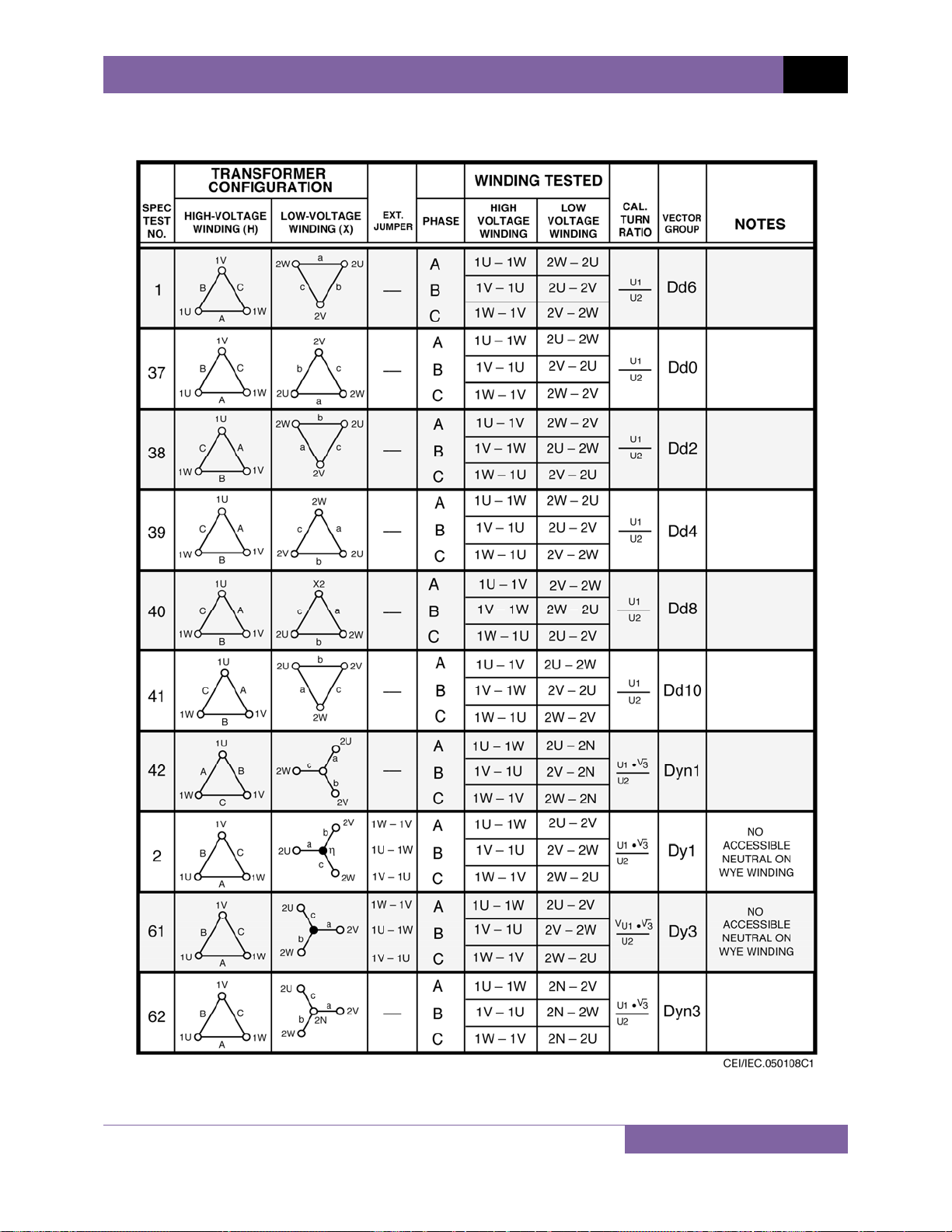
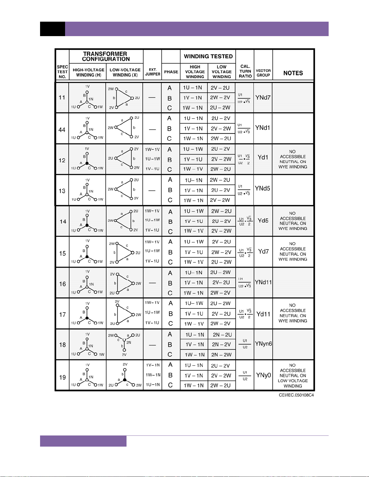
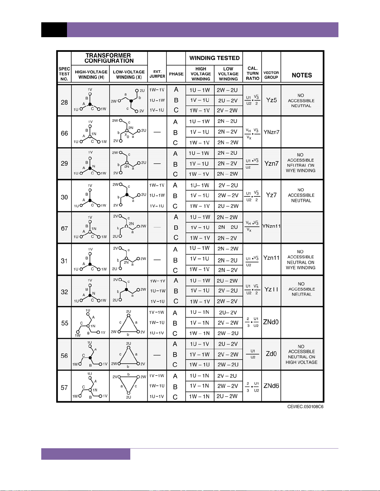
APPENDIX C – CEI/IEC 60076-1 Transformer Descriptions
70
Page 75

REV 1 ATRT-01/01B S3 USER’S MANUAL
71
Page 76

ATRT-01/01B S3 USER’S MANUAL REV 1
72
Page 77
REV 1 ATRT-01/01B S3 USER’S MANUAL
73
Page 78

ATRT-01/01B S3 USER’S MANUAL REV 1
74
Page 79
REV 1 ATRT-01/01B S3 USER’S MANUAL
75
Page 80

ATRT-01/01B S3 USER’S MANUAL REV 1
76
Page 81

REV 1 ATRT-01/01B S3 USER’S MANUAL
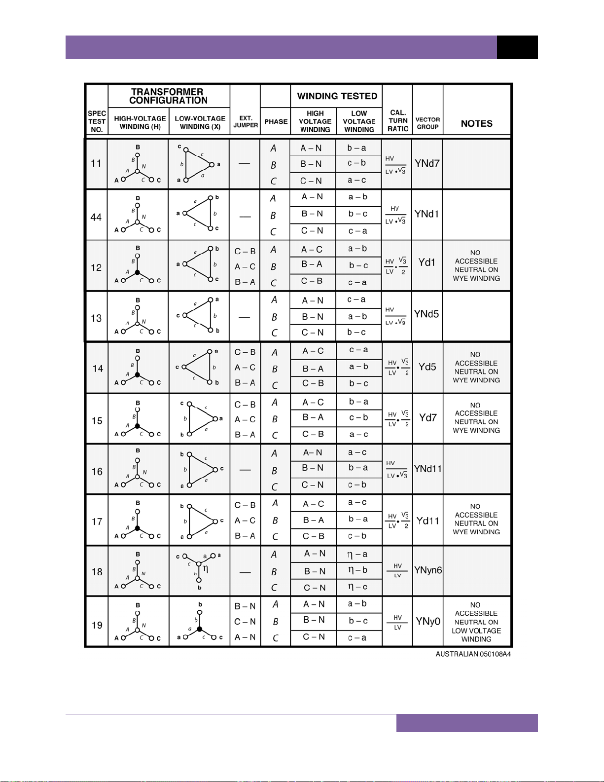
APPENDIX D – Australian Std.2374 Transformer Descriptions
77
Page 82

ATRT-01/01B S3 USER’S MANUAL REV 1
78
Page 83

REV 1 ATRT-01/01B S3 USER’S MANUAL
79
Page 84
ATRT-01/01B S3 USER’S MANUAL REV 1
80
Page 85

REV 1 ATRT-01/01B S3 USER’S MANUAL
81
Page 86

ATRT-01/01B S3 USER’S MANUAL REV 1
82
Page 87

REV 1 ATRT-01/01B S3 USER’S MANUAL
83
Page 88

1520 S. Hellman Ave • Ontario, CA 91761 • USA
Phone: 909-923-9390 • Fax: 909-923-9391
www.vanguard-instruments.com
Copyright © 2011 by Vanguard Instruments Company, Inc.
ATRT-01/01B S3 User’s Manual • Revision 1.0 • May 31, 2011 • TA
 Loading...