

VanDerLande High Capacity Diverter Installation Manual
Installation instructions
INSTALLATION MANUAL HIGH CAPACITY DIVERTER
Markcode
HCD
Document Nr A_DOC016742
Language EN
Revision D
© 2007 Vanderlande Industries b.v. All rights reserved. The information in this document is confidential and may be used only in accordance with the terms determined by Vanderlande Industries b.v. No
part of this publication may be altered, reproduced, stored in a retrieval system, or transmitted, in any form or by any means without the prior permission of Vanderlande Industries b.v.
Always use last revision!
Installation instruction:
Installation manual High Capacity Diverter
General information
Used symbols
$WARNING
R isk of personal injury
$CAUTION
Risk of damage to equipment
NOTE
Information that requires attention
Product identification
Nr Description
Related documents
Document Nr Description
-
Special tools
Ö
Õ
%
+
Input
Output
Special tools
Related documents
Item Nr Description
-
-EN-D 22-09-2008 Page 2 of 25

Installation instruction:
Installation manual High Capacity Diverter
Table of contents
....................................................................................................................5 Safety information
...........................................................................................................6 Technical specifications
.........................................................................................10 Types of support and dimensions.
.........12 Procedure Installation High Capacity Diverter (N55301-000 left, N55301-017 right)
..............................................................................17 1.1 General MCP hardware and software requirements
...........................................................................................................17 1.2 Electrical installation instructions
1.2.1 ................................................................................................................................17 Connecting sensor and motor wiring
1.2.2 ...........................................................................................................................................................18 Main power supply
1.2.3 .........................................................................................................................................18 BHS communication interface
.............................................................................................................19 1.3 Installation verification checklist
1.3.1 ..............................................................................................................................................................19 Visual inspection
1.3.2 ..............................................................................................................................................................20 Functionality test
1.3.3 .....................................................................................................................................21 Setting up the HCD environment
2 .........................24 Configurations and interfacing High Capacity Diverter with conveyors
......................................................................................................................24 2.1 Interface 45° merge divert
...........................................................................................................................24 2.2 Interface parallel divert
.......................................................................................................................25 2.3 Interface 90° chute divert
-EN-D 22-09-2008 Page 3 of 25
Installation instruction:
Installation manual High Capacity Diverter
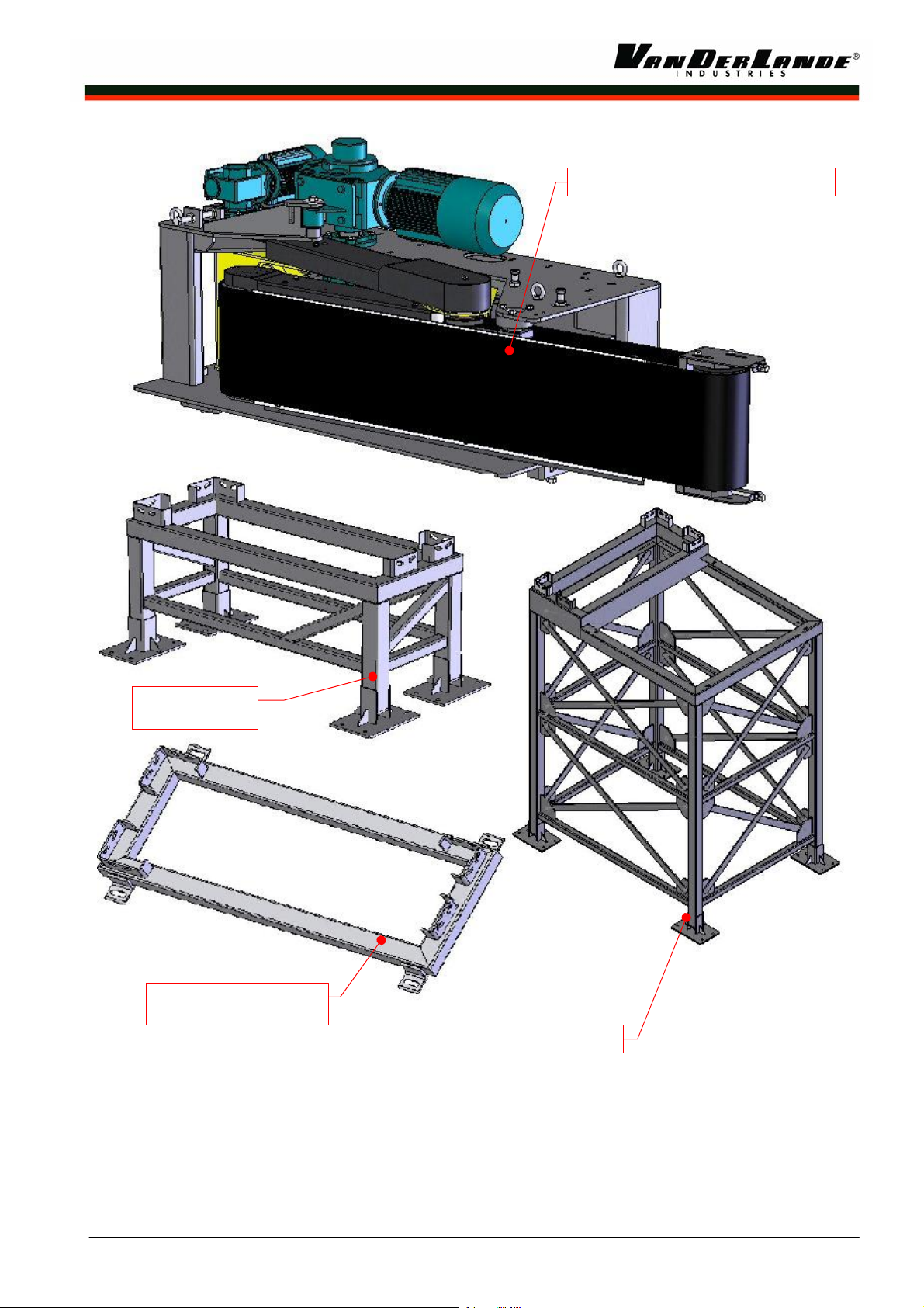
HIGH CAPACITY DIVERTER
STANDARD
SUPPORT
CEILING HANGER
SUPPORT
HIGH SUPPORT
-EN-D 22-09-2008 Page 4 of 25

Installation instruction:
Installation manual High Capacity Diverter
Safety information
The High Capacity Diverter (HCD) is designed to handle baggage and / or packages. Handling persons and / or creatures with the HCD is strictly prohibited.
No water or fluids may be used to clean the HCD.
In order to exclude any danger to the user or other persons and to avoid any damage, the unit is to be maintained and operated by appropriately trained personnel.
Work on electrical equipment may only be carried out by qualified electricians.
Installation contractors and/or mechanical engineers are always re sponsible for safety and have to work according the local safety requirements/regulations.
$WARN ING e Prior to any installation, service and maintenance work, the plant's main switch must b
switched off and secured to prevent switching on again.
$WARNING es disabled is dangerous. The danger area must Adjusting the plant with the safety featur
be secured to prevent access by other persons.
-EN-D 22-09-2008 Page 5 of 25
Installation instruction:
Installation manual High Capacity Diverter
Technical specifications
¾ The HCD will be offered in three separated parts namely:
1 Standard Support (N55301-030 left,-031 right) or High Support (N55301-032 left, -034 right) or Ceiling
hanger Support (N55301-070 left, -072 right (1pc),
2 High Capacity Diverter (N55301-000 left, or N55301-017 right) (1pc)
3 Control Cabinet (1pc)
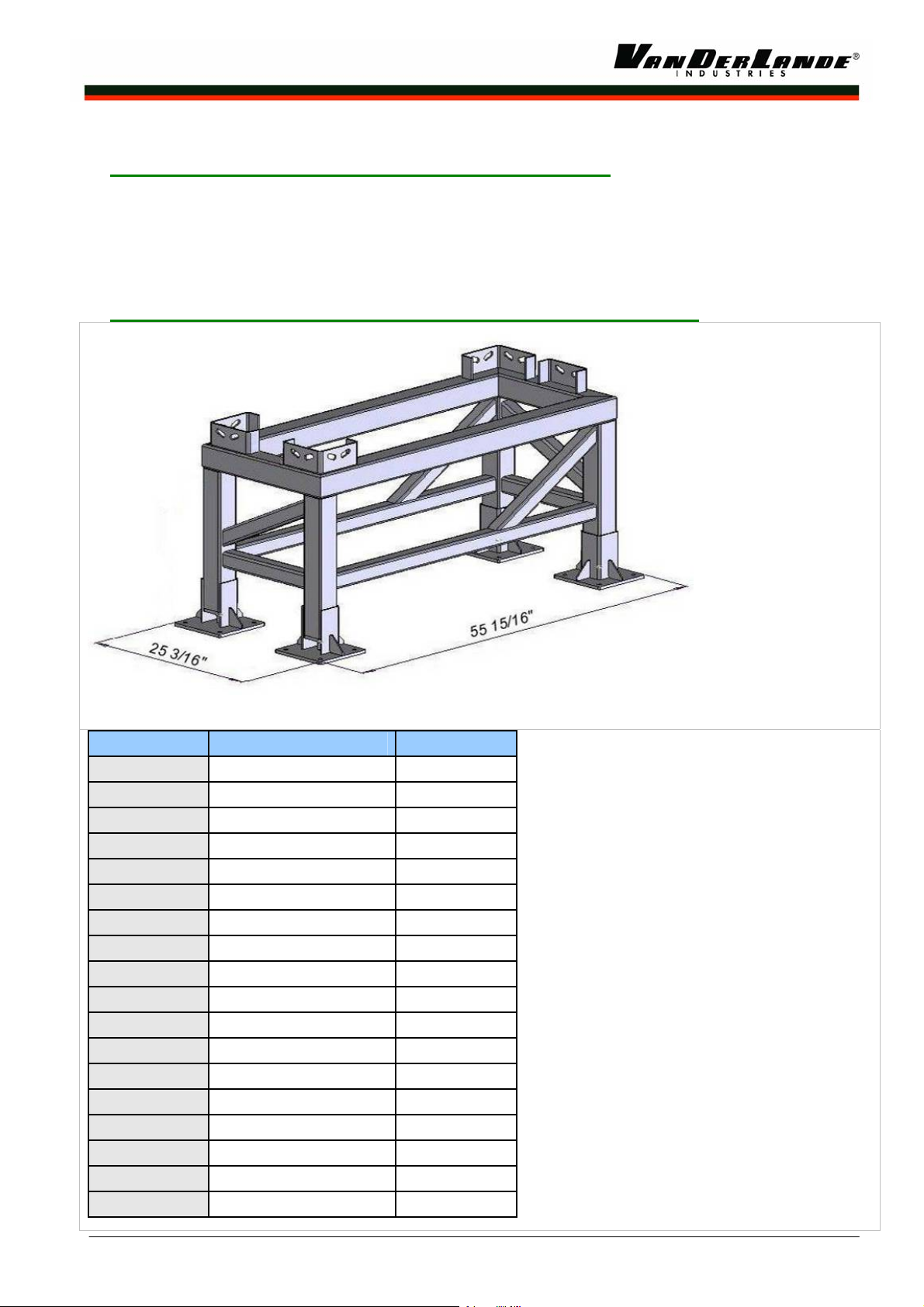
Standard Support (N55301-030 left, N55301-031 right, left is drawn¾ )
Figure 1 Low Support
Dash Number Top of Belt (In) Weight (Lb) 00001 12 7/8 to 14 27/32 86.4 00002 14 27/32 to 16 25/32 89.7 00003 16 25/32 to 18 21/32 92.8 00004 18 21/32 to 20 23/32 95.9 00005 20 23/32 to 22 11/16 99 00006 22 11/16 to 24 21/32 136.2 00007 24 21/32 to 26 5/8 139.3 00008 26 5/8 to 28 19/32 152.1 00009 28 19/32 to 30 9/16 164.9 00010 30 9/16 to 32 9/162 154.5 00011 32 9/16 to 34 17/32 170.8 00012 34 17/32 to 36 1/2 174.1 00013 36 1/2 to 38 15/32 177.2 00014 38 15/32 to 40 7/16 179.8 00015 40 7/16 to 42 13/32 183.4 00016 42 13/32 to 44 3/8 186.5 00017 44 3/8 to 46 17/32 189.2 00018 46 11/32 to 48 5/16 192.6
-EN-D 22-09-2008 Page 6 of 25
Installation instruction:
Installation manual High Capacity Diverter
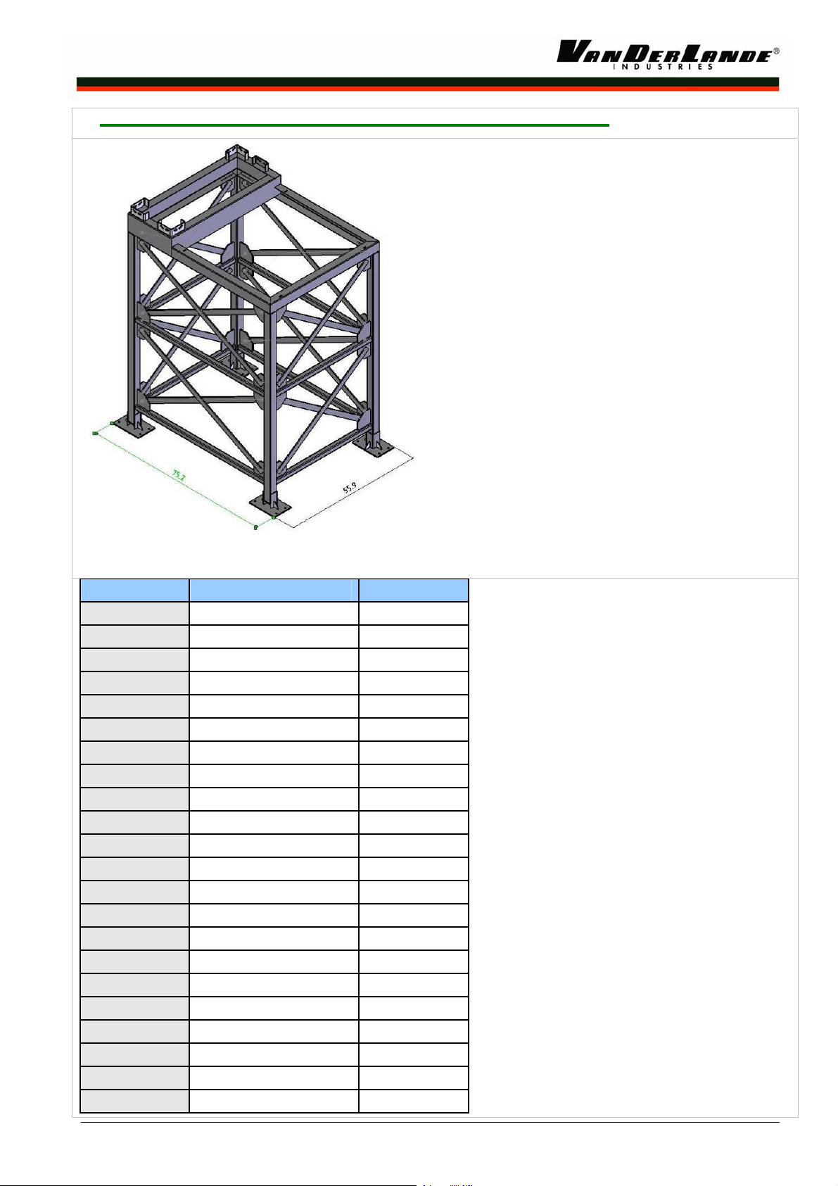
¾ High Support (N55301-032 Left, N55301-034 Right, Left is drawn
Figure 2 High Support
Dash Number Top of Belt (In) Weight (Lb) 00001 48 1/4 to 50 1/4 289.4 00002 50 1/4 to 52 1/4 394 00003 52 1/4 to 54 1/4 399 00004 54 1/4 to 56 1/8 403.5 00005 56 1/8 to 581/8 408.6 00006 56 1/8 to 60 1/8 413.7 00007 60 1/8 to 62 1/8 418.8 00008 62 1/8 to 64 606.5 00009 64 to 66 610.7 00010 66 to 68 615 00011 68 to 70 619.3 00012 70 to 71 7/8 623.7 00013 71 7/8 to 73 7/8 628.1 00014 73 7/8 to 75 7/8 632.5 00015 75 7/8 to 77 7/8 637 00016 77 7/8 to 79 3/4 641.6 00017 79 3/4 to 81 3/4 646.2 00018 81 3/4 to 83 3/4 650.8 00019 83 3/4 to 85 3/4 655.5 00020 85 3/4 to 87 5/8 661.2 00021 87 5/8 to 89 5/8 665.6 00022 89 5/8 to 91 5/8 667.8
-EN-D 22-09-2008 Page 7 of 25

Installation instruction:
Installation manual High Capacity Diverter
¾ Ceiling Hanger Supp ort (N55301-071 Left, N55301-072 Right, Left is drawn
Figure 3 Ceiling Hanger Support
Dash Number Top of Belt (In) Weight (Lb) 00001 7 to 8 70
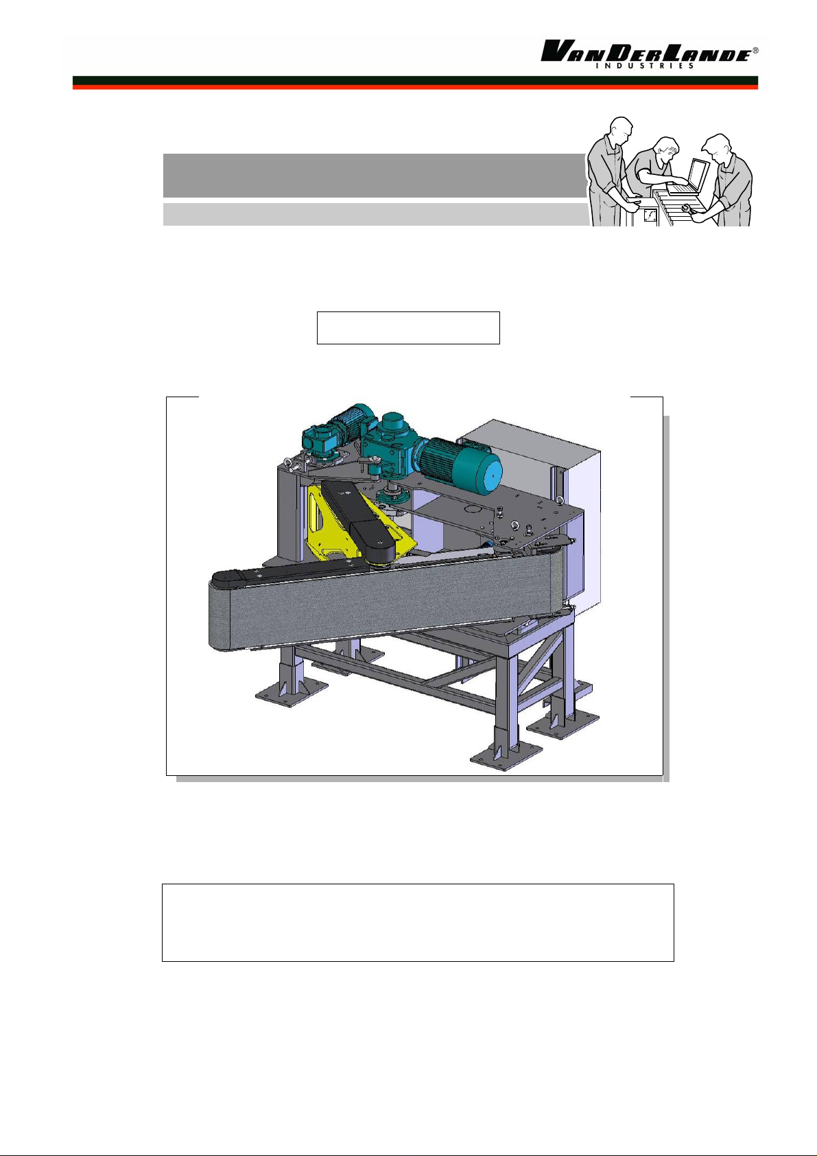
¾ High Capacity Diverter (N55301-001 left, N55301-017 right, left is drawn)
Figure 4 HCD
Dimensions (LxWxH): 79 1/2 x 26 1/8 X 29 7/8"
Weight: 1245 Lb
Centre of mass: See figure 5
-EN-D 22-09-2008 Page 8 of 25
 Loading...