


 Loading...
Assembly instruction
ASSEMBLY MANUAL HIGH CAPACITY DIVERTER
Markcode HCD
|
|
|
|
|
|
|
|
|
|
|
|
|
|
|
|
|
|
|
|
|
|
|
|
|
|
|
|
|
|
Document Nr |
A_DOC016452 |
|
|
|
|
|
Language |
EN |
|
|
|
|
|
Revision |
F |
|
|
|
© 2007 Vanderlande Industries b.v. All rights reserved. The information in this document is confidential and may be used only in accordance with the terms determined by Vanderlande Industries b.v. No part of this publication may be altered, reproduced, stored in a retrieval system, or transmitted, in any form or by any means without the prior permission of Vanderlande Industries b.v.
Always use last revision!

Assembly instruction:
Assembly manual High Capacity Diverter
General information
|
Used symbols |
|
|
|
|
|
|
Ö |
Input |
|
$WARNING |
|
||
|
|
Õ |
Output |
|
|
Risk of personal injury |
|||
|
|
Special tools |
||
|
|
|
% |
|
|
|
|
|
Related documents |
|
$CAUTION |
|
+ |
|
|
|
|
||
|
|
|
|
|
Risk of damage to equipment
NOTE
Information that requires attention
Product identification
Nr |
Description |
|
|
Related documents |
|
|
|
Document Nr |
Description |
- |
|
Special tools |
|
|
|
Item Nr |
Description |
N55301-313 (1x) |
Hoisting tool small |
N55301-320 (1x) |
Hoisting tool large |
|
|
A_DOC016452-EN-F |
23-12-2008 |
Page 2 of 32 |

Assembly instruction: |
|
|
Assembly manual High Capacity Diverter |
|
|
Table of contents |
|
|
Safety information.................................................................................................................... |
4 |
|
Procedure |
Assembly Divert Blade (N55301-006 left / N55301-018 right) ............................ |
5 |
Procedure |
Assembly Reaction Beam (N55301-002 left / N55301-016 right) ..................... |
13 |
Procedure |
Assembly HCD (N55301-000 left / N55301-017 right) ...................................... |
16 |
A_DOC016452-EN-F |
23-12-2008 |
Page 3 of 32 |

Assembly instruction:
Assembly manual High Capacity Diverter
Safety information
The High Capacity Divert (HCD) is designed to handle baggage and / or packages. Handling persons or creatures with the HCD is strictly prohibited.
Installation contractor or installation engineers are responsible for safety and should work according the local safety requirements/regulations.
$WARNING $WARNING $WARNING
Before test running, check if the HCD is fixed well.
Before test running be sure that nobody is present in the surrounding area of the HCD!
When glue or other chemical liquid is used, read the prescriptions of the supplier. Use protecting clothes, gloves and safety glasses.
A_DOC016452-EN-F |
23-12-2008 |
Page 4 of 32 |

Assembly instruction:
Assembly manual High Capacity Diverter
Procedure Assembly Divert Blade (N55301-006 left / N55301-018 right)
$WARNING
Heavy part!
High Capacity Diverter
Reaction Beam
Divert Blade
NOTE NOTE
All treaded connections should be secured with Loctite nr. 243 !
All non-preserving interfaces of parts must be preserved with rust protection lubricant to prevent rust.
A_DOC016452-EN-F |
23-12-2008 |
Page 5 of 32 |
Assembly instruction:
Assembly manual High Capacity Diverter
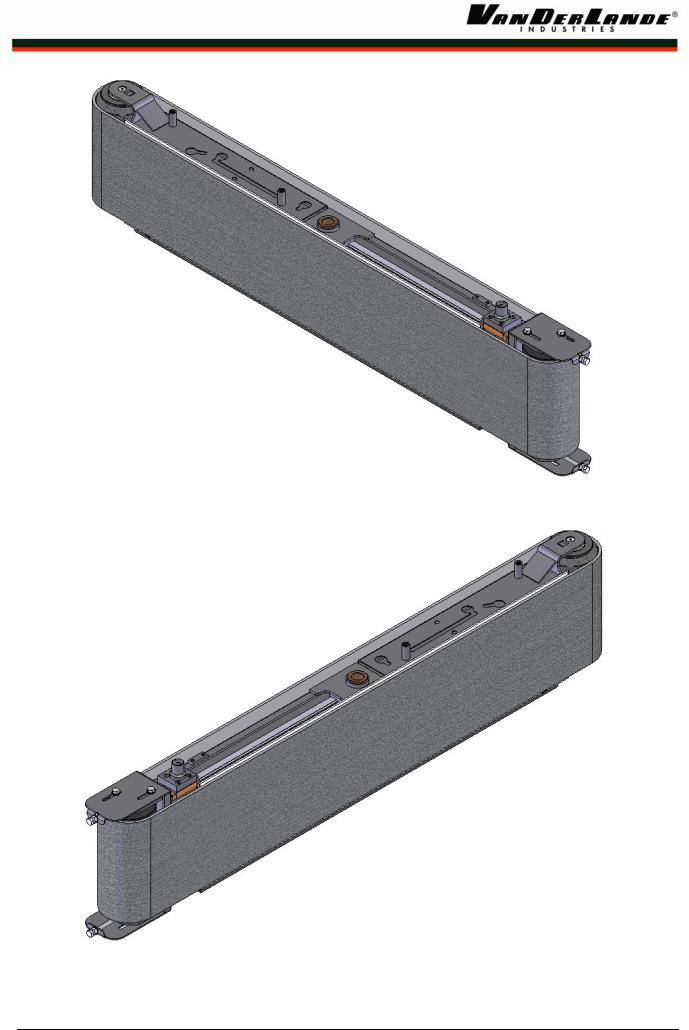
Figure 1 Divert Blade Left (N55301-006)
Figure 2 Divert Blade Right (N55301-018)
A_DOC016452-EN-F |
23-12-2008 |
Page 6 of 32 |
Assembly instruction:
Assembly manual High Capacity Diverter
¾ Divert Blade Left / Right (left is drawn)
|
|
|
|
|
|
|
|
|
|
|
|
$WARNING N55301-305 / 314 are heavy parts ! |
|
||||
|
|
|
|
|
|
|
||
|
|
|
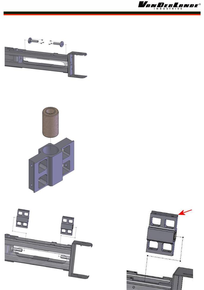
Step 1 Mounting the axle torque bush. |
|
||||
|
|
|
Ö |
N55301-305 (1x) |
Divert Blade Frame left execution |
|
||
|
|
|
|
or |
|
|
|
|
|
|
|
Ö |
N55301-314 (1x) |
Divert Blade Frame right execution |
|
||
|
|
|
Ö |
N55301-637 (2x) |
Shaft Flexible Bush |
|
||
|
|
|
Ö |
002412-01025 (6x) Hex. socket countersunk head screw |
|
|||
|
|
|
|
|
M10x25 |
|
||
|
|
|
|
|
|
|
|
|
Figure 3 Axle torque bush |
|
% |
N55301-313 (1x) |
Hoisting tool small |
|
|
||
|
% |
N55301-320 (1x) |
Hoisting tool large |
|
|
|||
|
|
|
|
|
||||
|
|
|
|
|
|
|
||
|
|
|
|
|
|
|
|
|
|
|
|
Step 2 Mounting the torque bushings and the block |
|
||||
|
|
|
|
guiding rails. |
|
|
||
|
|
|
Ö |
N55301-636 (2x) |
Mounting block guiding rail |
|
||
|
|
|
Ö |
N03805-80001 (2x) Hinge bush 55-30-94-89.5 |
|
|||
|
|
|
|
|
(supplier Meadler 68500800) |
|
||
|
|
|
|
|
|
|||
|
|
|
NOTE Make sure that the edge (see red arrow) on the |
|
||||
|
|
|
|
mounting block is mounted on the back side |
|
|||
|
|
|
|
of the divert blade frame |
|
|||
Figure 4 Assemble mounting block guiding rail |
|
|
|
|
|
|
|
|
|
|
|
|
|
|
|
|
|
Figure 5 Torque bushing and mounting block guide rail |
|
|
|
|
|
|
||
|
|
|
|
|
|
|
|
|
|
|
|
|
|
|
|
|
|
A_DOC016452-EN-F |
23-12-2008 |
Page 7 of 32 |

Assembly instruction:
Assembly manual High Capacity Diverter
|
|
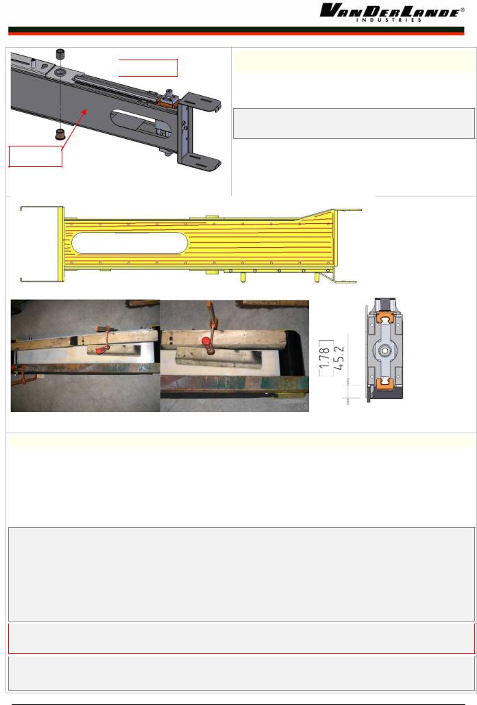
Step 3 Mounting the guide rail. |
|
|
Mount lubrication |
|
Ö N55301-010 (2x) |
Guiding Rail HGR30T with carrier |
|
tank on this side |
|
|
||
|
|
HGH30CA E2 (supplier Hiwin) |
|
|
Top and Bottom |
|
|
|
|
|
Ö 002311-08030 (8x) |
Hex. head bolt M8x30 |
|
|
|
|
Ö 002764-00008 (8x) |
Spring lock washer M8 |
|
|
|
|
||
|
|
|
|
|
|
|
NOTE If carrier (N04936-00030) and rail (N04936-00600) |
|
|
|
|
delivered separated, first mount the carrier and rail |
|
|
|
|
according supplier's information by using the |
|
|
|
|
special delivered black plastic strip. |
|
|
|
|
NOTE For maintenance purposes mount the lubrication |
|
|
|
|
tank on the "backside" (ETU) of the Divert Blade |
|
|
|
|
NOTE Make sure that the mounting blocks are in a straight |
|
|
|
|
and a parallel position to each other. |
|
|
|
Impact side |
|
|
|
|
|
|
|
|
|
|
|
|
|
|
|
|
|
|
|
|
Figure 6 Guide rail |
|
|
|
|||||||
|
|
|
|
|
|
|
|
|
|
|
|
|
|
|
|
|
|
|
|
|
|
|
|
|
|
|
|
|
|
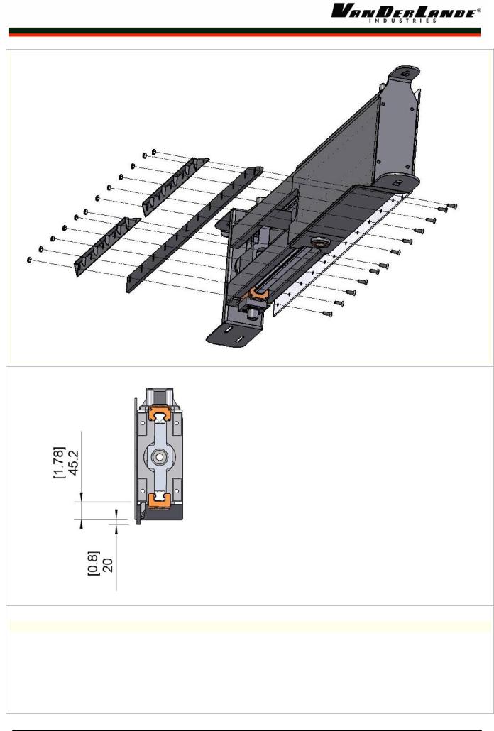
Step 4 Mounting the top and bottom shaft linear |
|
|
|
|
|
|
|
N55301-639 |
|
guiding system |
|
||
|
|
|
|
|
|
|
|
Ö N55301-635 (2x) |
Plate shaft |
|
|
|
|
|
|
|
|
|
|
||
|
|
|
|
|
|
|
|
Ö N55301-638 (1x) |
Shaft bottom |
|
|
|
|
|
|
|
|
|
Ö N55301-639 (1x) |
Shaft top |
|
|
|
|
|
|
|
|
|
Ö 002412-01630 (2x) |
Hex. socket countersunk head screw |
|
|
|
|
|
|
|
|
|
|
M16x30 |
|
|
|
|
|
|
|
|
|
Ö 002419-08020 (8x) |
Hex. socket head cap screw M8x20 |
|
|
|
|
|
|
|
|
|
Ö N55301-667 (2x) |
Washer |
|
|
|
|
|
|
|
|
|
Ö 002311-12025 (2x) |
Hex. head bolt M12x25 |
|
|
|
|
|
|
|
|
|
|
|
|
|
|
|
|
|
|
|
|
NOTE Make sure that the edge (see red arrow) on the |
|
|
|
Impact side |
|
|
|
|
|
shaft plate is mounted on the back side of the |
|
||
|
|
|
|
|
|
|
|
divert blade frame |
|
|
|
|
|
|
|
|
|
|
|
||
|
|
|
|
N55301-638 |
|
|
|
|||
|
|
|
|
|
NOTE The bolts for the hinge bush must be tightened with |
|
||||
|
|
|
|
|
|
|
|
|
||
|
|
|
|
|
|
|
|
|
||
|
|
|
|
|
|
|
|
a torque of 93Nm (85LbFt) |
|
|
Figure 8 Bolts Hinge Bush
Figure 7 Topand bottom shaft
A_DOC016452-EN-F |
23-12-2008 |
Page 8 of 32 |
Assembly instruction:
Assembly manual High Capacity Diverter
 N55301-321
Impact side
Step 5 Mounting the slide bearings turn point Divert Blade
ÖN06520-00001 (1x) Oil free bushing.
ÖN55301-321 (N06520-00001), machined part
NOTE Make sure that both bearings are in line and have the right tolerances (see checklist).
Figure 9 Slide bearings turn point.
Figure 10 Impact plate
Step 6 Glue the impact plate
ÖN55301-668 (1x) Impact plate left execution
Öor
ÖN55301-522 (1x) Impact plate right execution
ÖN07232-07063 Loctite 7063, Surface cleaner
Ö |
N07232-00770 |
Loctite 770, |
Primer |
Ö |
N07232-00435 |
Loctite 435, |
Adhesive fast glue |
NOTE
1)Clean both surfaces of the divert plate and the impact plate once with Loctite 7063 cleaner
2)Make both the divert blade and the Impact plate surfaces rough with sand paper
3)Clean both surfaces twice (divert blade and Impact plate) with Loctite 7063 cleaner
4)Spread out Loctite 770 primer on the total Impact plate surface, using a clean tissue might be an option
5)Spread out Loctite 435 on the front plate of the divert plate (see red lines, Figure 10), handling time more than 24h
6)Now the Impact plate can be placed on the divert blade,
$WARNING when the Impact plate contacts the divert blade the glue already have 40% adhesive strength, do not try to move the Impact plate after contact
7)Fasten the Impact plate by using wooden beams and use 12-14 clamps (see Figure 10), or by using a fixture tool
8)After 1/2 hour the clamps and the wooden beams may be removed, the glue process is finished, now there is 80% adhesive strength.
A_DOC016452-EN-F |
23-12-2008 |
Page 9 of 32 |
Assembly instruction:
Assembly manual High Capacity Diverter
Step 7 Mounting the Rubber sweep
Ö N55301-689 (1x) |
Rubber sweep |
ÖN55301-561 (2x) Bracket rubber sweep only for HCD Right
ÖN55301-548 (2x) Bracket rubber sweep only for HCD Left
Ö002412-00825 (12x) Hex. socket countersunk head screw M8x25
Ö002371-56008 (12x) Nut Hex Lock Nyloc M8
A_DOC016452-EN-F |
23-12-2008 |
Page 10 of 32 |
Loading...