


 Loading...
O&M Manual
Viper Pusher O&M Manual
O&M Manual
VIPER PUSHER O&M MANUAL
Markcode DP
|
|
|
|
|
|
|
|
|
|
|
|
|
|
|
|
|
|
|
|
|
|
|
|
|
|
|
|
|
Document number |
G0045-072-00001 |
|
|
|
|
|
Language |
EN |
|
|
|
|
|
|
|
Original document |
|
|
|
|
Revision |
A.11 |
|
|
|
|
|
|
|
|
|
|
|
|
|
|
|
|
|
|
G0045-072-00001-EN-A.11 |
1 of 87 |

O&M Manual
Viper Pusher O&M Manual
General
Safety information
This manual may contain information for the assembly, removal and replacement of hazardous equipment. Take appropriate safety measures to avoid injury.
The following instructions are for use by qualified personnel only.
Used symbols
Special tools
Referenced documents
Warning:
Risk of personal injury
Caution:
Risk of damage to equipment
Note:
Information that requires attention
Used icons
The following icons may be used in this manual
Risk |
Icon |
Risk |
Icon |
|
|
|
|
Caution, risk of danger |
|
Caution, keep safe distance |
|
|
|
|
|
Caution, risk of electric shock |
|
Storing goods prohibited |
|
|
|
|
|
Caution, moving parts |
|
Walking on system prohibited |
|
|
|
|
|
Caution, rotating parts |
|
|
|
|
|
|
|
G0045-072-00001-EN-A.11 |
2 of 87 |

O&M Manual
Viper Pusher O&M Manual
Procedural information
The English edition is the original document.
Figures in this manual are based on one variant and can differ from the actual unit. Refer to the mechanical drawings for the specific dash variant details.
Relevant drawings
|
Nr |
Description |
|
|
|
||
|
N55200-065 |
Assy, Viper Pusher, Round Paddle, VFD, No Clutch Brake |
|
|
N99100-00001 |
Viper Pusher VFD Control Panel w/ Proximity Switches |
|
|
|
|
|
Referenced documents
 Doc nr Description
No table of contents entries found.
Special tools
 Item nr Description
No table of contents entries found.
Dodge belt tension tester (Part number 109082)
Illustration information
Sequence (Seq) |
Procedure number |
|
Denotes the procedure |
||
Denotes the sequence to |
||
in which the |
||
be followed. |
||
subassembly is built. |
||
|
Denotes number of times |
Label |
procedure needs to be |
Refers to the item(group) |
carried out |
in the spare parts list. |
G0045-072-00001-EN-A.11 |
3 of 87 |

O&M Manual
Viper Pusher O&M Manual
Revision list for English edition
|
Revision: |
|
|
Description |
|
|
|
|
|
||
|
|
|
|
|
|
|
A |
|
First edition |
||
|
|
|
|
|
|
G0045-072-00001-EN-A.11 |
4 of 87 |

O&M Manual
Viper Pusher O&M Manual
Table of contents
1 |
Operation manual ................................................................................................................................................... |
7 |
||
|
1.1 |
System Overview ........................................................................................................................................... |
7 |
|
|
1.1.1 |
Parallel Divert............................................................................................................................................. |
7 |
|
|
1.1.2 |
Perpendicular Divert .................................................................................................................................. |
8 |
|
|
1.2 |
Baggage weight and size limitations ............................................................................................................. |
9 |
|
|
1.2.1 |
Standard baggage ..................................................................................................................................... |
9 |
|
|
1.2.2 Baggage that can be processed by the system but requires special handling ....................................... |
10 |
||
|
1.2.3 |
Fragile baggage ....................................................................................................................................... |
10 |
|
|
1.2.4 |
Odd-Size Baggage .................................................................................................................................. |
10 |
|
|
1.3 |
system operation ......................................................................................................................................... |
10 |
|
|
1.4 |
Theory of operation...................................................................................................................................... |
10 |
|
|
1.4.1 |
Run Mode ................................................................................................................................................ |
11 |
|
|
1.4.2 |
Jog Mode ................................................................................................................................................. |
11 |
|
|
1.5 |
VFD Control Panel....................................................................................................................................... |
11 |
|
|
1.6 |
Pusher Connections .................................................................................................................................... |
12 |
|
|
1.7 |
Operational Safety ....................................................................................................................................... |
13 |
|
|
1.7.1 |
Pre-operating Procedure ......................................................................................................................... |
13 |
|
|
1.7.2 Jam detection, Jam clearance and Restart Procedure ........................................................................... |
14 |
||
2 |
Maintenance Manual ............................................................................................................................................ |
15 |
||
|
2.1 |
Glossary of terms and Identication .............................................................................................................. |
15 |
|
|
2.2 |
Description of system equipment ................................................................................................................ |
15 |
|
|
2.3 |
Electrical Control Sequnce of Operation ..................................................................................................... |
16 |
|
|
2.4 |
Exploded views and Recommended Spare Parts ....................................................................................... |
17 |
|
|
2.4.1 Assy, Viper Pusher, Round Paddles, VFD, No Clutch Brake .................................................................. |
17 |
||
|
2.4.2 Assy, Viper Pusher, Motor + Motor Support + No Clutch Brake ............................................................. |
18 |
||
|
2.4.3 Assy, Viper Pusher, Long Arm Damper................................................................................................... |
19 |
||
|
2.4.4 Assy, Viper Pusher, Round Paddle and Polyester Cover ....................................................................... |
19 |
||
|
2.4.5 Assy, Viper Pusher, Long Arm................................................................................................................. |
20 |
||
|
2.4.6 Assy, Viper Pusher, Reducer Housing w/ Proximity Switches ................................................................ |
21 |
||
|
2.4.7 Assy, Viper Pusher, Short Arm ................................................................................................................ |
22 |
||
|
2.5 |
Maintenance safety procedures .................................................................................................................. |
23 |
|
|
2.5.1 |
Pre-Operating Procedures ....................................................................................................................... |
23 |
|
|
2.5.2 |
Equipment Lockout Procedure ................................................................................................................ |
23 |
|
|
2.5.3 |
Safety Summary ...................................................................................................................................... |
23 |
|
|
2.6 |
Service, Inspection, and Preventative Maintenance ................................................................................... |
24 |
|
|
2.6.1 |
Inspection................................................................................................................................................. |
24 |
|
|
2.6.2 |
Lubrication ............................................................................................................................................... |
24 |
|
|
2.6.3 |
Cleaning Methods .................................................................................................................................... |
26 |
|
|
2.6.4 |
Adjustments ............................................................................................................................................. |
26 |
|
|
2.6.5 Short arm timing belt adjustment ............................................................................................................. |
30 |
||
|
2.6.6 |
Drive belt adjustment ............................................................................................................................... |
32 |
|
|
2.7 |
Troubleshooting ........................................................................................................................................... |
34 |
|
|
|
|
||
G0045-072-00001-EN-A.11 |
5 of 87 |
|||

O&M Manual |
|
|
Viper Pusher O&M Manual |
|
|
2.8 |
Removal and Installation Procedures .......................................................................................................... |
36 |
2.8.1 |
Replacement Steps ................................................................................................................................. |
36 |
2.8.2 Torque Values for Standard American Screws ....................................................................................... |
50 |
|
2.8.3 |
Mechanical Installation ............................................................................................................................ |
50 |
2.8.4 Removal and Installation Purchased Parts.............................................................................................. |
53 |
|
2.9 |
Illustrated Parts Information......................................................................................................................... |
57 |
2.9.1 |
Manufacturer's Literature ......................................................................................................................... |
57 |
2.9.2 |
Mechanical Drawings............................................................................................................................... |
59 |
2.9.3 |
Electrical Drawings .................................................................................................................................. |
79 |
App.1. |
Periodic Maintenance Inspection and Lubrication Chart ............................................................................. |
84 |
App.2. |
Environmental Requirements ...................................................................................................................... |
86 |
App.3. |
List of Lubricants.......................................................................................................................................... |
87 |
G0045-072-00001-EN-A.11 |
6 of 87 |
O&M Manual
Viper Pusher O&M Manual
1 OPERATION MANUAL
1.1 SYSTEM OVERVIEW
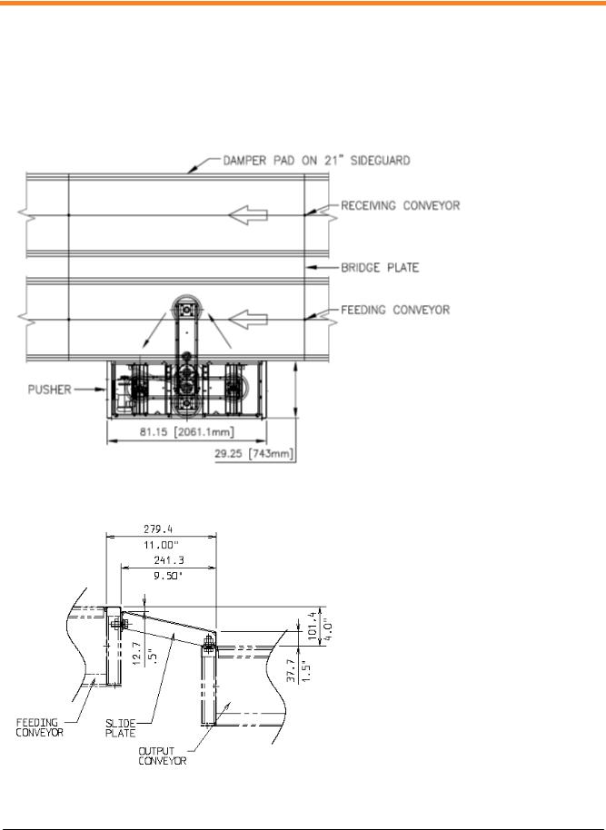
1.1.1 Parallel Divert
F 1 Parallel Divert (Top View)
F 2 Bridge Plate (Side View)
G0045-072-00001-EN-A.11 |
7 of 87 |
O&M Manual
Viper Pusher O&M Manual
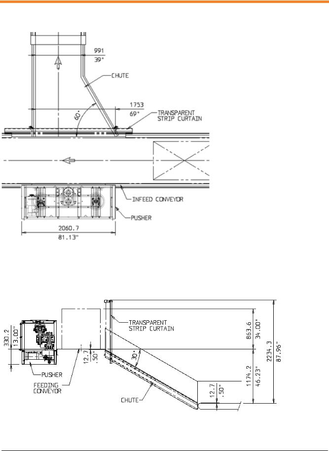
1.1.2 Perpendicular Divert
F 3 Perpendicular Divert (Top View)
The chute starts on the reference line (measured from the side panel of the pusher). The preferred chute width is 81" (2060mm). The minimum width is 69" (1755mm).
F 4 Perpendicular Divert (Side View)
G0045-072-00001-EN-A.11 |
8 of 87 |

O&M Manual
Viper Pusher O&M Manual
1.2BAGGAGE WEIGHT AND SIZE LIMITATIONS
1.2.1 Standard baggage |
|
|
|
|
|
|
|||
|
|
|
|
|
|
|
|
|
|
|
Length |
|
Width |
|
Height |
|
Weight |
||
|
|
|
|
|
|
|
|
|
|
|
inch |
|
mm |
inch |
mm |
inch |
mm |
lb |
kg |
|
|
|
|
|
|
|
|
|
|
Minimum |
6 |
|
152.4 |
3 |
76.2 |
3 |
76.2 |
1 |
0.45 |
|
|
|
|
|
|
|
|
|
|
Maximum |
54 |
|
291.6 |
33 |
838.2 |
34 |
863.6 |
120 |
54.4 |
|
|
|
|
|
|
|
|
|
|
The following table lists the type of baggage that can be processed by the Viper pusher:
T 1 Standard baggage type
G0045-072-00001-EN-A.11 |
9 of 87 |

O&M Manual
Viper Pusher O&M Manual
1.2.2 Baggage that can be processed by the system but requires special handling
For longer baggage, a modified program is required to push the bag in the center.
The following baggage can be processed, but must be in a tub before processing.
T 2 Baggage requiring special handling
1.2.3 Fragile baggage
The Viper pusher cannot process fragile items.
1.2.4 Odd-Size Baggage
The Viper pusher cannot process odd-size baggage.
1.3SYSTEM OPERATION
The pusher transfer baggage from one conveyor to another. These conveyors can be parallel or perpendicular See chapter 1 System overview. The pusher is provided clockwise or counterclockwise, according to the conveyor direction. To be able to automatically sort baggage, the pusher is connected to the BHS.
The pusher is mounted next to the feeding conveyor. This conveyor has a narrow width to ensure the sorting of different baggage sizes. The reach over the belt is 35.84" (910mm). The speed of the conveyor is related to the capacity of the pusher.
Pusher capacity |
60 bpm |
80 bpm |
|
|
|
Conveyor speed |
260 fpm (80 m/min) |
345 fpm (105 m/min) |
|
|
|
The pusher has a high capacity which means that it moves at great speeds. The force used for pushing is considerable which means that all personnel in the pusher operation area must use great caution. The pusher stops in the home position to avoid interference with passing baggage.
1.4THEORY OF OPERATION
The Viper pusher functions in two operation modes, the Run mode and the Jog mode. In the Run mode divert operations are controlled by a trigger signal from the host Baggage Handling System (BHS) in which the pusher is integrated or the cycle button located on the control panel. In the Jog mode, the arm's motion is controlled by operators located on the pusher's control panel.
G0045-072-00001-EN-A.11 |
10 of 87 |
O&M Manual
Viper Pusher O&M Manual
1.4.1 Run Mode
In the Run mode the host controller in the BHS sends a trigger signal to the pusher. A trigger signal is released by the BHS host controller after the decision is made to divert a bag. The pusher's arm cycles out to push the bag onto the takeaway conveyor, then returns to the home position to allow non-diverting bags to pass.
1.4.2 Jog Mode
In the Jog mode of operation the pusher does not respond to trigger signals received from the host controller. Instead, the pusher can be operated manually by the jog switch located on the pusher's control panel. The release of the jog selector switch will stop the motion of the arm.
This mode is intended for troubleshooting and testing during general operations, and after performing maintenance work.
1.5VFD CONTROL PANEL
The control panel for the pusher connects the pusher unit to the BHS. The front panel, (see Figure F 5), comprise of the following:
F 5 Viper Pusher VFD Control Panel
Disconnect: Switches on the main power for the pusher for normal operations.
Cycle Pushbutton: Completes 1 full cycle of the pusher when pressed.
Run/Jog Switch: Selects the mode of operation for the pusher. For normal operation of the pusher within the BHS the Run/Jog switch should be in the Run position. The Cycle pushbutton will only function in Run Mode. To allow manual control of the movement of the pusher's arm via the FWD Jog/ REV Jog switch, place the Run/Jog Switch in the Jog position.
Rev/Fwd Jog Switch: 3 position momentary selector switch used to control the movement of the pusher arm. This switch will only function when the Run/Jog Switch is in the Jog position. Place the switch in the Rev position to run the arm in a counterclockwise direction. Place the switch in the Fwd position to run the arm in a clockwise direction.
G0045-072-00001-EN-A.11 |
11 of 87 |

O&M Manual
Viper Pusher O&M Manual
1.6PUSHER CONNECTIONS
All connections for the viper pusher are detailed in the panel schematic, including all pre-fabricated cables. The Viper pusher has the following connections, (see Table T 3):
BHS to pusher control panel.
Pusher control panel to Motor.
Pusher control panel to Prox. Switches supplied with a pre-fabricated cable.
T 3 Pusher Connections
Functionality |
From BHS |
To Pusher Control Panel |
|
|
|
Trigger Signal |
O: _ _ |
Terminal:X1:1 |
|
|
|
120Vac Line |
|
Terminal:X1:L1 |
|
|
|
120Vac Neutral |
|
Terminal:X1:N |
|
|
|
Drive Fault |
I:_ _ |
Terminal:X1:14 |
|
|
|
Home Prox Sw. |
I:_ _ |
Terminal:X1:2 |
|
|
|
Stop Relay |
I:_ _ |
Terminal:X1:4 |
|
|
|
Disconnects On/Off |
I:_ _ |
Terminal:X1:L2 |
|
|
|
Jog Mode |
I:_ _ |
Terminal:X1:3 |
|
|
|
Functionality |
From Pusher Control Panel |
To Motor |
|
|
|
Power L1 |
Terminal:X3:T1 |
T1 |
|
|
|
Power L2 |
Terminal:X3:T2 |
T2 |
|
|
|
Power L3 |
Terminal:X3:T3 |
T3 |
|
|
|
Ground |
Terminal:X3:GND |
GND |
|
|
|
Functionality |
From Pusher Control Panel |
To Home Prox. Sw. |
|
|
|
Signal |
Terminal:X2:24VDC+ |
1 |
|
|
|
+24VDC |
Terminal:X2:4 |
2 |
|
|
|
-24VDC |
Terminal:X2:24VDC- |
3 |
|
|
|
Functionality |
From Pusher Control Panel |
To Decel Prox. Sw. |
|
|
|
Signal |
Terminal:X2:24VDC+ |
1 |
|
|
|
+24VDC |
Terminal:X2:5 |
2 |
|
|
|
-24VDC |
Terminal:X2:24VDC- |
3 |
|
|
|
G0045-072-00001-EN-A.11 |
12 of 87 |

O&M Manual
Viper Pusher O&M Manual
1.7 OPERATIONAL SAFETY
1.7.1Pre-operating Procedure
1.Be sure that the MCP Controller main power disconnect is OFF and locked out and the PUSHER disconnect switch is OFF before opening the protective cover or making adjustments.
2.Be careful handling electric equipment.
3.Be sure that all guards are in place before resuming operation.
4.Keep hands and loose clothing away from moving parts.
5.Be careful when touching a bearing. A faulty bearing may be hot enough to cause burns.
6.Keep all conveyor belts and beds clear of obstructions and debris.
7.Do not use any conveyor as a rest, work platform, or conveyance for tools, parts, or personnel.
8.Observe all company directives and policies, the caution and warning signs posted on conveyors and instructions in this and other manuals.
9.When cleaning dust with compressed air, use eye protection and avoid breathing the dust.
G0045-072-00001-EN-A.11 |
13 of 87 |

O&M Manual
Viper Pusher O&M Manual
1.7.2 Jam detection, Jam clearance and Restart Procedure
See Section 2.5.3 Safety Summary
1.Stop the feeding conveyor line.
2.On the Pusher control panel:
−Switch the Disconnect OFF.
−Leave the Run/Jog switch in the Run position.
3.Manually move the pusher’s paddle arm in order to clear the jam.
4.Reposition any bag(s) onto an open area of the conveyor belt outside the path of the pusher’s operation.
5.On the Pusher control panel:
−Switch the Disconnect ON.
−Press the Cycle Button.
The arm should cycle back to the home position.
6.Restart the conveyor line and resume normal operation.
G0045-072-00001-EN-A.11 |
14 of 87 |

O&M Manual
Viper Pusher O&M Manual
2 MAINTENANCE MANUAL
2.1GLOSSARY OF TERMS AND IDENTICATION
REAR
FRON
F 6 Pusher Top View (Covers not shown)
F 7 Pusher Rear View (Covers not shown)
2.2DESCRIPTION OF SYSTEM EQUIPMENT
LONG ARM
MOTOR
PADDLE
SHORT ARM
SHORT ARM
REDUCER HOUSING
 LONG ARM
 PADDLE
 MOTOR
MOTOR
The pusher consists of two paddles that rotate. A short arm and a long arm create the movement. The use of these two arms results in a triangular movement, which uses less space next to the conveyor, and creates a velocity in the direction of the conveyor belt.
The paddles are mounted symmetrically at the long arm. The round paddle pusher does not have a timing belt drive in the long arm.
The long arm rotates at its center, which is mounted at the short arm. The short arm is mounted at the reducer axle. The reducer is driven by a v-belt drive, which is powered by a motor.
Power Requirements: |
3 x 480V, 3.4A (Canada: 3 x 575V, 2.5A) |
Overall Dimensions (L x W x H): |
81.13" x 29.25" x 37.83" (2060.7mm x 743mm x 961mm) |
Weight: |
approximately 1150lb (522kg) |
G0045-072-00001-EN-A.11 |
15 of 87 |
O&M Manual
Viper Pusher O&M Manual
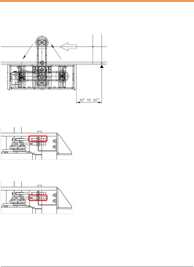
2.3ELECTRICAL CONTROL SEQUNCE OF OPERATION
A photo-eye is placed 30" to 60" upstream. If the pusher is used in a particular divert onto a chute, then a second photo-eye can be installed to detect an obstruction on the chute.
F 8 Photo-eye Location
The home proximity switch is used to detect the home position.
F 9 Home Proximity Switch
The deceleration proximity switch is used to engage the brake to stop the arm's motion.
F 10 Deceleration Proximity Switch
G0045-072-00001-EN-A.11 |
16 of 87 |

O&M Manual
Viper Pusher O&M Manual
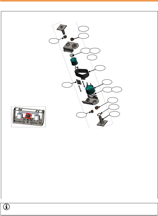
2.4 EXPLODED VIEWS AND RECOMMENDED SPARE PARTS 2.4.1 Assy, Viper Pusher, Round Paddles, VFD, No Clutch Brake
N55200-065 Assy, Viper Pusher, Round Paddles, VFD, No Clutch Brake
|
|
A25 |
A27 |
A45 |
A26 |
|
||
|
|
A45
A46
A40
A42
A48
A47
A41
A43
|
|
|
|
A44 |
|
|
|
|
|
|
|
Item |
Part Number |
Description |
Spare |
||
|
|
|
|
|
|
A40 |
N00750-11716 |
QD keyseat bushing SF 1-7/16 Dodge #120463 |
Yes |
||
|
|
|
|
|
|
A41 |
N00750-01716 |
QD keyseat bushing SDS 1-7/16 Dodge #120403 |
Yes |
||
|
|
|
|
|
|
A42 |
- |
|
3/8" Square Key Stock, 2" Long |
|
|
|
|
|
|
|
|
A43 |
- |
|
3/8" Square Key Stock, 1.25" Long |
|
|
|
|
|
|
|
|
A44 |
N55200-066-00001 |
Assy, Viper Pusher, Motor + Motor Support + No CB, 480V |
Yes |
||
|
|
N55200-066-00002 |
Assy, Viper Pusher, Motor + Motor Support + No CB, 575V |
|
|
|
|
|
|
|
|
A45 |
N55200-007-00001 |
Assy, Viper Pusher, Long Arm Damper |
|
||
|
|
|
|
|
|
A46 |
N55200-053-00001 |
Assy, Viper Pusher, Long Arm |
Yes* |
||
|
|
|
|
|
|
A47 |
N55200-067-00060 |
Assy, Viper Pusher, Reducer Housing w/ Proximity Switches, 60bpm |
Yes* |
||
|
|
N55200-067-00080 |
Assy, Viper Pusher, Reducer Housing w/ Proximity Switches, 80bpm |
|
|
|
|
|
|
|
|
A48 |
N55200-004-00001 |
Assy, Viper Pusher, Short Arm |
Yes* |
||
|
|
|
|
|
|
*Items can be ordered as an assembled item for ease of installation or its subcomponents can be ordered as separate items.
G0045-072-00001-EN-A.11 |
17 of 87 |

O&M Manual
Viper Pusher O&M Manual
2.4.2 Assy, Viper Pusher, Motor + Motor Support + No Clutch Brake
N55200-066 Assy, Viper Pusher, Motor + Motor Support + No Clutch Brake
|
|
|
|
A3 |
|
|
|
|
|
|
A2 |
A5 |
|
|
|
|
|
|
||
|
|
|
|
|
|
|
|
|
|
|
A6 |
A4 |
|
|
|
|
|
|
|
|
|
|
|
|
|
|
|
|
Item |
Part Number |
Description |
|
Spare |
|
|
|
|
|
|
|
|
|
A1 |
N04880-09133 |
V-belt type B (21/32"x13/32"), Gates B68K 9133-0068, 71"(not shown) |
Yes |
||
|
|
|
|
|
|
|
|
A2 |
N04840-01210 |
Taper-Lock Bushing w/ Key Way 1210-7/8", Dodge #117079 |
Yes |
||
|
|
|
|
|
|
|
|
A3 |
N55200-792-00001 |
Viper Pusher, Taper Lock Sheeve |
|
Yes |
|
|
|
|
|
|
|
|
|
A4 |
N00700-53587 |
Motor, 2HP, 480V, 60Hz,145TC Baldor #VEM3587T |
|
Yes |
|
|
|
N00700-93587 |
Motor, 2HP, 575V, 60Hz,145TC Baldor #VEM3587T-5 |
|
||
|
|
|
|
|
|
|
|
A5 |
N55200-769-00001 |
Viper Pusher, Motor Mount Buffer Rail |
|
Yes |
|
|
|
|
|
|
|
|
|
A6 |
N03801-00002 |
Damper, 5/16"-18, 1" x 1", 50SH A, M/F, McMaster #9376147 |
Yes |
||
|
|
|
|
|
|
|
Note: For ease of installation, the motor and motor support can be ordered as one unit rather than ordering its subcomponents and installing the parts individually.
G0045-072-00001-EN-A.11 |
18 of 87 |
O&M Manual
Viper Pusher O&M Manual
2.4.3 Assy, Viper Pusher, Long Arm Damper
N55200-007 Assy, Viper Pusher, Long Arm Damper
A8
A7
Item |
Part Number |
Description |
Spare |
|
|
|
|
A7 |
N55200-674-01300 |
Viper Pusher, Rubber Damper, A=1.30" |
Yes |
|
|
|
|
A8 |
N55200-674-00950 |
Viper Pusher, Rubber Damper, A=0.95" |
Yes |
|
|
|
|
2.4.4 Assy, Viper Pusher, Round Paddle and Polyester Cover
A9
 A10
A10
Item |
Part Number |
Description |
Spare |
|
|
|
|
A9 |
N55200-051-00001 |
Assy, Viper Pusher, Round Paddle |
Yes |
|
|
|
|
A10 |
N02004-00001 |
Polyester Cover Stitched w/ Elastic Cord |
Yes |
|
|
|
|
G0045-072-00001-EN-A.11 |
19 of 87 |

O&M Manual
Viper Pusher O&M Manual
2.4.5 Assy, Viper Pusher, Long Arm
N55200-053 Assy, Viper Pusher, Long Arm
A16 |
A16 |
|
A14
A14 |
A11 |
|
A15 |
||
|
||
A15 |
A14 |
|
|
||
A14 |
A16 |
|
|
||
A16 |
|
A13 |
A12 |
A12 |
|
Item |
Part Number |
Description |
Spare |
|
|
|
|
A11 |
N04931-90107 |
Bearing, 1-7/16", 207, 3-bolt, F3B-SLX-107, Dodge #128191 |
Yes |
|
|
|
|
A12 |
N55200-766-00001 |
Viper Pusher, Long Arm Assembly, Aluminum Axle |
Yes |
|
|
|
|
A13 |
N55200-651-00001 |
Viper Pusher, Long Arm Central Axle |
Yes |
|
|
|
|
A14 |
N04901-00018 |
Slide Thrust Bearing 1-15/16" X 2-5/8" X 1/8", ST-6284-4 |
Yes |
|
|
|
|
A15 |
N02768-02193 |
Clamp Collar 2-Piece ZP,Climax #2C-193-Z, 1-15/16" #04319480 |
Yes |
|
|
|
|
A16 |
N55200-661-00001 |
Viper Pusher, Long Arm Bearing Sheave |
Yes |
|
|
|
|
Note: For ease of installation, the long arm can be ordered as one unit rather than ordering its subcomponents and installing the parts individually.
G0045-072-00001-EN-A.11 |
20 of 87 |
O&M Manual
Viper Pusher O&M Manual
2.4.6 Assy, Viper Pusher, Reducer Housing w/ Proximity Switches
N55200-067 Assy, Viper Pusher, Reducer Housing w/ Proximity Switches
 A21
A21
A17
A18
|
|
|
|
A24 |
|
|
|
|
A20 |
A22 |
|
|
|
|
|
|
|
|
|
|
A19 |
A23 |
|
|
|
|
|
|
|
|
|
|
|
|
|
Item |
Part Number |
Description |
|
Spare |
|
|
|
|
|
|
|
A17 |
N55200-305-00001 |
Weldment, Viper Pusher, Proximity Switch Cam |
Yes |
||
|
|
|
|
|
|
A18 |
N06002-00001 |
Proximity Sensor w/ Cordset |
|
Yes |
|
|
|
|
|
|
|
A19 |
N04840-12103 |
Ring Ret Taper-Lock Bushing 1210-3/4", Dodge #117154 (60 bpm) |
Yes |
||
|
|
N04840-01610 |
Ring Ret Taper-Lock Bushing KW 1610-3/4",Dodge #117158 (80 bpm) |
|
|
|
|
|
|
|
|
A20 |
N55200-791-00001 |
Viper Pusher, Taper Lock Sheeve, 60 bpm |
|
Yes |
|
|
|
N55200-792-00001 |
Viper Pusher, Taper Lock Sheeve, 80 bpm |
|
|
|
|
|
|
|
|
A21 |
N55200-355-00001 |
Viper Pusher, Reducer Shaft |
|
Yes |
|
|
|
|
|
|
|
A22 |
N00700-00125 |
Reducer WSCXT125T Taper Dodge # 241082 (60 bpm) |
Yes |
||
|
|
N00700-00115 |
Reducer WSCXT115T Taper Dodge # 241091 (80 bpm) |
|
|
|
|
|
|
|
|
A23 |
N04931-90107 |
Bearing, 1-7/16", 207, 3-bolt, F3B-SLX-107-ABHS, Dodge #128191 |
Yes |
||
|
|
|
|
|
|
A24 |
N06002-01716 |
Bushing 1-7/16 TDT 1 Tapered Dodge #241292 |
Yes |
||
|
|
|
|
|
|
Note: For ease of installation the reducer housing can be ordered as one unit rather than ordering its subcomponents and installing the parts individually.
G0045-072-00001-EN-A.11 |
21 of 87 |
O&M Manual
Viper Pusher O&M Manual
2.4.7 Assy, Viper Pusher, Short Arm
N55200-004 Assy, Viper Pusher, Short Arm
 A29
A29
A31
A30
A27 A28
 A26
A26
A25
A32
A39
A33 A34
|
A37 |
|
A36 |
A38 |
A35 |
|
Item |
Part Number |
Description |
Spare |
|
|
|
|
A25 |
N04879-00966 |
Timing Belt, Gates HTD-966-14M 115, Din5296, L=966 |
Yes |
|
|
|
|
A26 |
N04858-32014 |
Sprocket, QD HTD, 2-1/8" Bore, P32-14M-115-SK, Dodge #110858 |
Yes |
|
|
|
|
A27 |
N00750-00218 |
QD keyseat bushing SK 2-1/8 Dodge #120439 |
Yes |
|
|
|
|
A28 |
N55200-633-00001 |
Viper Pusher, Short Arm Upper Housing Key Stock |
|
|
|
|
|
A29 |
N55200-307-00001 |
Weldment, Viper Pusher, Short Arm Upper Axle |
Yes |
|
|
|
|
A30 |
N55200-632-00001 |
Viper Pusher, Short Arm Upper Housing Flange Bearing |
Yes |
|
|
|
|
A31 |
N55200-631-00001 |
Viper Pusher, Short Arm Upper Housing Bearing Sleeve |
Yes |
|
|
|
|
A32 |
N55200-684-00001 |
Viper Pusher, Short Arm Main Sprocket |
Yes |
|
|
|
|
A33 |
N00750-00258 |
QD keyseat bushing E 2-5/8 Dodge #120516 |
Yes |
|
|
|
|
A34 |
- |
5/8" X 9/16" X 2" Square Key Stock |
|
|
|
|
|
A35 |
N55200-309-00001 |
Weldment, Viper Pusher, Short Arm Lower Axle |
Yes |
|
|
|
|
A36 |
N55200-639-00001 |
Viper Pusher, Short Arm Lower Housing Thrust Bearing |
Yes |
|
|
|
|
A37 |
N55200-685-00001 |
Viper Pusher, Short Arm Lower Housing Bearing Sleeve |
Yes |
|
|
|
|
A38 |
N55200-684-00001 |
Viper Pusher, Short Arm Main Sprocket |
Yes |
|
|
|
|
A39 |
N55200-012-00001 |
Assy, Viper Pusher, Tension Arm |
Yes |
|
|
|
|
Note: For ease of installation, the short arm can be ordered as one unit rather than ordering its subcomponents and installing the parts individually.
G0045-072-00001-EN-A.11 |
22 of 87 |

O&M Manual
Viper Pusher O&M Manual
2.5MAINTENANCE SAFETY PROCEDURES
2.5.1 Pre-Operating Procedures
See App.3 List of Lubricants
See Section 1.7.1 Pre-operating Procedure
2.5.2 Equipment Lockout Procedure
See Section 2.5.3 Safety Summary
1.Stop the feeding conveyor line.
2.On the Pusher control panel:
−Switch the Disconnect OFF.
−Leave the Run/Jog switch in the Run position.
2.5.3Safety Summary
1.Be sure that the MCP Controller main power disconnect is OFF and locked out and the pusher disconnect switch is OFF before opening the protective cover or making adjustments.
2.Be careful handling electric equipment.
3.Be sure that all guards are in place before resuming operation.
4.Keep hands and loose clothing away from moving parts.
G0045-072-00001-EN-A.11 |
23 of 87 |

O&M Manual
Viper Pusher O&M Manual
5.Be careful when touching a bearing. A faulty bearing may be hot enough to cause burns.
6.Keep all conveyor belts and beds clear of obstructions and debris.
7.Do not use any conveyor as a rest, work platform, or conveyance for tools, parts, or personnel.
8.Observe all company directives and policies, the caution and warning signs posted on conveyors and instructions in this and other manuals.
9.When cleaning dust with compressed air, use eye protection and avoid breathing the dust.
Refer to Section 2.8.2: Torque Values for Standard American Screws for proper torque values on standard fasteners unless otherwise directed.
2.6SERVICE, INSPECTION, AND PREVENTATIVE MAINTENANCE
2.6.1 Inspection
See App.1 Periodic Maintenance Inspection and Lubrication Chart
2.6.2 Lubrication
2.6.2.1Reducer
1. Follow safety procedures. |
See Section 2.5.3 Safety Summary |
2.On the Pusher control panel, switch the Disconnect OFF.
G0045-072-00001-EN-A.11 |
24 of 87 |

O&M Manual
Viper Pusher O&M Manual
3.Wipe all dirt and grease from the reducer drain plug, oil lever plug, and vent ports with a clean cloth.
4.Remove fill and drain plugs from reducer and drain the oil.
5.Flush residual oil from the reducer using a cleaning agent.
6.Clean and re-install magnetic drain plug.
|
B = Breather Plug |
D = Drain Plug |
7. Clean and replace all plugs removed from |
L = Oil Level Plug |
P = Plug |
reducer, except fill port plug. |
|
|
8.Fill the reducer with 1 quart (0.95 liter) of recommended oil. App.3 List of Lubricants shows the recommended oils and lubricants.
9.Do not overfill, which will cause overheating. A low oil level will cause gear failure.
10.Do not use oils containing additives such as graphite or molybdenum disulfide. Additives can damage the reducer. The pour point of the selected lubricant should be at least 10°F lower than the minimum expected ambient starting
temperature. |
Note: V-belt is not shown |
|
11.Clean and replace fill port plug.
12.Wipe away excess oil from reducer and surrounding area.
G0045-072-00001-EN-A.11 |
25 of 87 |
O&M Manual
Viper Pusher O&M Manual
13.Put all safety covers in place and restore pusher to normal operation.
2.6.3 Cleaning Methods
Photocells |
− |
Soft camel hair brush |
|
− |
Clean with optical tissue moistened with a lens cleaning solution |
|
|
approved for use with coated optics |
|
|
|
2.6.4 Adjustments |
|
|
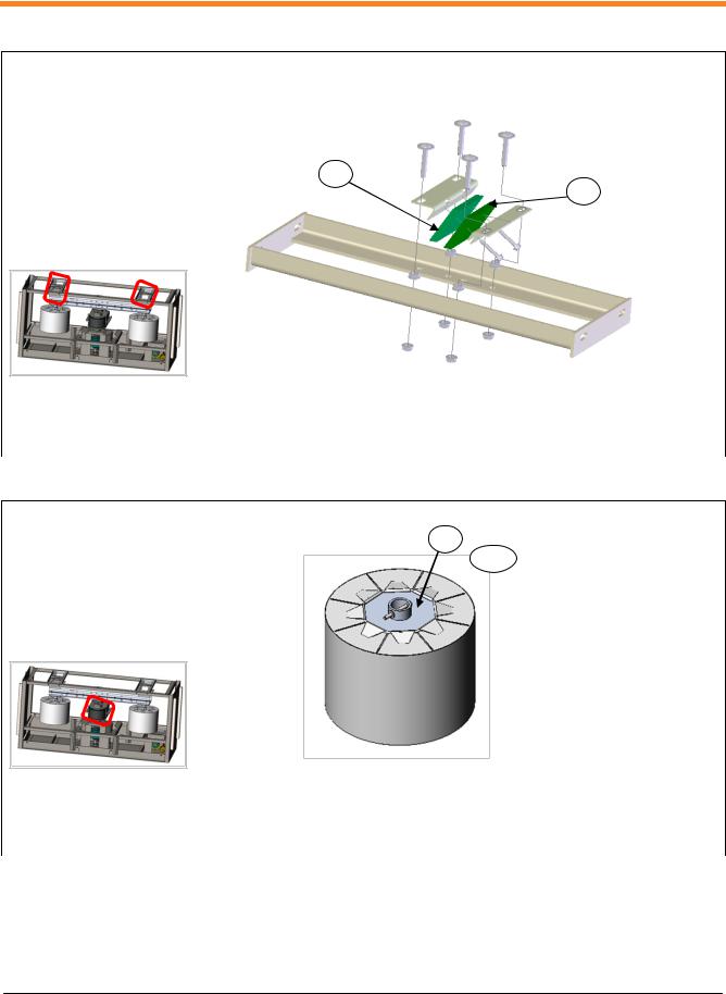
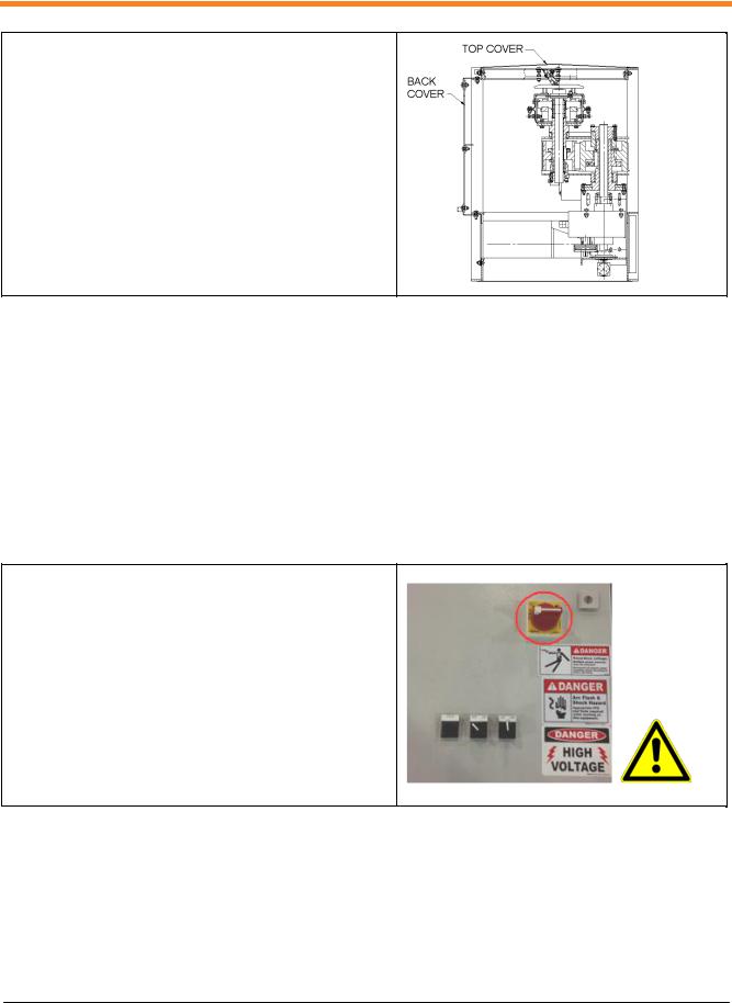
2.6.4.1Damper Pads
Damper pads should be deflected 1/16" to 1/8" (2mm to 4mm).
1.Be sure that the MCP Controller main power disconnect is OFF and locked out and the Pusher disconnect switch is OFF before opening the protective cover or making adjustments.
G0045-072-00001-EN-A.11 |
26 of 87 |
O&M Manual
Viper Pusher O&M Manual
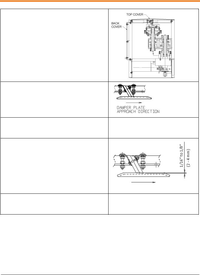
2. Remove top cover.
3.Adjust the front and rear mounting bracket adjustment nuts so that the full width of the damper pad is resting on the damper plate, with top of the mounting brackets level.
4.Measure the height of the mounting brackets above their frame.
5.Tighten the lower adjustment nuts evenly to lower the mounting brackets and damper pads 1/16” to 1/8” (2 to 4 mm).
6.Tighten the top adjustment nuts to secure the adjustment.
G0045-072-00001-EN-A.11 |
27 of 87 |
Loading...