

Page 1
M212022EN-D
User Guide
Vaisala Indigo compatible
humidity and temperature probes
HMP3, HMP4, HMP5, HMP7, HMP8, HMP9, MMP8, TMP1
Page 2

PUBLISHED BY
Vaisala Oyj
Vanha Nurmijärventie 21, FI-01670 Vantaa, Finland
P.O. Box 26, FI-00421 Helsinki, Finland
+358 9 8949 1
Visit our Internet pages at www.vaisala.com.
© Vaisala Oyj 2020
No part of this document may be
reproduced, published or publicly
displayed in any form or by any means,
electronic or mechanical (including
photocopying), nor may its contents be
modified, translated, adapted, sold or
disclosed to a third party without prior
written permission of the copyright holder.
Translated documents and translated
portions of multilingual documents are
based on the original English versions. In
ambiguous cases, the English versions are
applicable, not the translations.
The contents of this document are subject
to change without prior notice.
Local rules and regulations may vary and
they shall take precedence over the
information contained in this document.
Vaisala makes no representations on this
document’s compliance with the local
rules and regulations applicable at any
given time, and hereby disclaims any and
all responsibilities related thereto.
This document does not create any legally
binding obligations for Vaisala towards
customers or end users. All legally binding
obligations and agreements are included
exclusively in the applicable supply
contract or the General Conditions of Sale
and General Conditions of Service of
Vaisala.
This product contains software developed
by Vaisala or third parties. Use of the
software is governed by license terms and
conditions included in the applicable
supply contract or, in the absence of
separate license terms and conditions, by
the General License Conditions of Vaisala
Group.
Page 3

Table of contents
Table of contents
1. About this document.....................................................................................7
1.1 Version information.......................................................................................... 7
1.2 Related manuals................................................................................................7
1.3 Documentation conventions........................................................................... 8
1.4 Trademarks........................................................................................................ 8
2. Product overview............................................................................................ 9
2.1 Probe structure................................................................................................. 9
2.2 Basic features and options.............................................................................. 9
2.3 Output parameters......................................................................................... 10
2.4 Additional features with Indigo 200 series transmitters.............................11
2.5 Safety................................................................................................................. 11
2.6 ESD protection.................................................................................................12
2.7 Regulatory compliances................................................................................. 12
2.7.1 FCC Part 15 compliance statement.........................................................12
2.7.2 Canada ICES-003 compliance statement............................................. 13
3. Installation........................................................................................................14
3.1 HMP3 probe......................................................................................................15
3.2 HMP4 probe..................................................................................................... 16
3.3 HMP5 probe......................................................................................................17
3.4 HMP7 probe......................................................................................................18
3.5 HMP8 probe..................................................................................................... 19
3.5.1 Attaching ball valve kit to process........................................................20
3.6 HMP9 probe......................................................................................................21
3.6.1 Installing HMP9 through a cable gland.................................................22
3.7 MMP8 probe.................................................................................................... 23
3.8 TMP1 probe......................................................................................................24
3.9 Wiring...............................................................................................................25
4. Configuration with Insight software..................................................... 27
4.1 Vaisala Insight software.................................................................................27
4.2 Installing driver for the USB service cable...................................................27
4.3 Connecting to Insight software.................................................................... 28
4.4 Configuration options....................................................................................29
5. Using probe with Indigo transmitters................................................... 31
5.1 Indigo 200 series transmitter overview........................................................31
5.2 Attaching probe to Indigo 200 series transmitter..................................... 33
5.3 Wireless configuration interface overview..................................................34
5.4 Connecting to wireless configuration interface..........................................34
5.5 Logging in to wireless configuration interface........................................... 35
6. Maintenance....................................................................................................36
6.1 Cleaning the probe.........................................................................................36
6.1.1 Chemical tolerance................................................................................. 36
1
Page 4

HMP3, HMP4, HMP5, HMP7, HMP8, HMP9, MMP8, TMP1 User Guide M212022EN-D
6.2 Changing the probe filter.............................................................................. 37
6.3 Replacing the HUMICAPâ R2 sensor........................................................... 37
6.4 Calibration and adjustment...........................................................................39
6.4.1 Adjustment points and requirements.................................................. 40
6.4.2 Adjusting measurement with Insight software.................................... 41
6.4.3 Adjusting measurement with Indigo 200 transmitter........................42
7. Troubleshooting............................................................................................46
7.1 Problem situations......................................................................................... 46
7.2 Error messages...............................................................................................46
8. Technical data................................................................................................49
8.1 HMP3 specifications.......................................................................................49
8.2 HMP4 specifications.......................................................................................52
8.3 HMP5 specifications.......................................................................................55
8.4 HMP7 specifications....................................................................................... 58
8.5 HMP8 specifications........................................................................................ 61
8.6 HMP9 specifications.......................................................................................64
8.7 MMP8 specifications.......................................................................................67
8.8 TMP1 specifications........................................................................................ 70
8.9 Accessories and spare parts..........................................................................72
Appendix A:
Modbus reference...................................................................77
A.1 Default communication settings...................................................................77
A.2 Function codes................................................................................................77
A.3 Data encoding.................................................................................................77
A.3.1 32-bit floating point or integer format................................................. 78
A.3.2 16-bit integer format...............................................................................78
A.4 Modbus registers............................................................................................ 78
A.4.1 Measurement Data Registers.................................................................79
A.4.2 Configuration registers...........................................................................82
A.4.3 Device identification objects................................................................. 85
A.4.4 Status registers........................................................................................85
A.4.5 Test value registers..................................................................................87
A.4.6 Modbus communication examples.......................................................88
Online store....................................................................................................... 91
Warranty.............................................................................................................91
Technical support.............................................................................................91
Recycling............................................................................................................91
2
Page 5

List of figures
Figure 1 Probe parts......................................................................................................... 9
Figure 2 Example installation........................................................................................14
Figure 3 HMP3 probe dimensions................................................................................15
Figure 4 HMP4 probe dimensions................................................................................16
Figure 5 HMP5 probe dimensions................................................................................17
Figure 6 Optional mounting flange 210696 dimensions....................................... 17
Figure 7 HMP7 probe dimensions................................................................................18
Figure 8 HMP8 probe dimensions................................................................................19
Figure 9 HMP9 probe dimensions................................................................................21
Figure 10 Installing HMP9 probe head through a cable gland..............................22
Figure 11 MMP8 dimensions...........................................................................................23
Figure 12 TMP1 probe dimensions................................................................................ 24
Figure 13 M12 5-pin A-coded male connector pinout............................................. 25
Figure 14 RS-485 wiring.................................................................................................. 25
Figure 15 Connecting probe to Insight........................................................................29
Figure 16 HMP5 in Insight software..............................................................................30
Figure 17 HMP7 attached to Indigo 200 series transmitter....................................31
Figure 18 HMP7 attached to Indigo 200 series transmitter with a cable...........32
Figure 19 Attaching the probe to Indigo 200 series transmitter......................... 33
Figure 20 Enabling and accessing wireless configuration interface
of Indigo 200................................................................................................... 34
Figure 21 Indigo login view.............................................................................................35
Figure 22 HMP3 probe head with filter removed......................................................38
Figure 23 Calibration page in the Indigo 200 wireless
configuration interface..................................................................................44
Figure 24 HMP3 humidity measurement accuracy as a function of
temperature.....................................................................................................50
Figure 25 HMP3 temperature measurement accuracy over full range............... 50
Figure 26 HMP3 probe dimensions...............................................................................52
Figure 27 HMP4 humidity measurement accuracy as a function of
temperature......................................................................................................53
Figure 28 HMP4 temperature measurement accuracy over full range............... 53
Figure 29 HMP4 probe dimensions...............................................................................55
Figure 30 HMP5 humidity measurement accuracy as a function of
temperature..................................................................................................... 56
Figure 31 HMP5 temperature measurement accuracy over full range............... 56
Figure 32 HMP5 probe dimensions...............................................................................58
Figure 33 HMP7 humidity measurement accuracy as function of
temperature......................................................................................................59
Figure 34 HMP7 temperature measurement accuracy over full range............... 59
Figure 35 HMP7 probe dimensions................................................................................61
Figure 36 HMP8 humidity measurement accuracy as a function of
temperature......................................................................................................62
Figure 37 HMP8 temperature measurement accuracy over full range............... 62
Figure 38 HMP8 probe dimensions.............................................................................. 64
List of figures
3
Page 6

HMP3, HMP4, HMP5, HMP7, HMP8, HMP9, MMP8, TMP1 User Guide M212022EN-D
Figure 39 Optional ball valve installation kit dimensions.......................................64
Figure 40 HMP9 probe dimensions...............................................................................67
Figure 41 Aw measurement accuracy..........................................................................68
Figure 42 MMP8 dimensions...........................................................................................69
Figure 43 TMP1 temperature measurement accuracy over full range.................70
Figure 44 TMP1 probe dimensions................................................................................. 71
Figure 45 Optional duct kit 215003 dimensions........................................................72
4
Page 7

List of tables
Table 1 Document versions (English)...........................................................................7
Table 2 Related Manuals...................................................................................................7
Table 3 Availability of output parameters.................................................................10
Table 4 Suitability of cleaning agents........................................................................ 36
Table 5 Troubleshooting table.....................................................................................46
Table 6 Measurement performance............................................................................49
Table 7 Operating environment.................................................................................. 50
Table 8 Inputs and outputs............................................................................................ 51
Table 9 Mechanical specifications................................................................................51
Table 10 Measurement performance............................................................................52
Table 11 Operating environment...................................................................................54
Table 12 Inputs and outputs........................................................................................... 54
Table 13 Mechanical specifications...............................................................................54
Table 14 Measurement performance............................................................................55
Table 15 Operating environment...................................................................................57
Table 16 Inputs and outputs............................................................................................57
Table 17 Mechanical specifications............................................................................... 57
Table 18 Measurement performance............................................................................58
Table 19 Operating environment.................................................................................. 60
Table 20 Inputs and outputs...........................................................................................60
Table 21 Mechanical specifications.............................................................................. 60
Table 22 Measurement performance.............................................................................61
Table 23 Operating environment...................................................................................63
Table 24 Inputs and outputs........................................................................................... 63
Table 25 Mechanical specifications...............................................................................63
Table 26 Measurement performance........................................................................... 64
Table 27 Operating environment...................................................................................65
Table 28 Inputs and outputs........................................................................................... 66
Table 29 Mechanical specifications...............................................................................66
Table 30 Measurement performance............................................................................67
Table 31 Operating environment...................................................................................68
Table 32 Inputs and outputs........................................................................................... 68
Table 33 Mechanical Specifications.............................................................................. 69
Table 34 Measurement performance............................................................................70
Table 35 Operating environment...................................................................................70
Table 36 Inputs and outputs............................................................................................ 71
Table 37 Mechanical specifications................................................................................71
Table 38 Connection cables.............................................................................................72
Table 39 Accessories......................................................................................................... 73
Table 40 Spare parts..........................................................................................................73
Table 41 Spare parts..........................................................................................................73
Table 42 Accessories......................................................................................................... 73
Table 43 Spare parts..........................................................................................................74
Table 44 Accessories......................................................................................................... 74
Table 45 Spare parts..........................................................................................................74
List of tables
5
Page 8

HMP3, HMP4, HMP5, HMP7, HMP8, HMP9, MMP8, TMP1 User Guide M212022EN-D
Table 46 Accessories......................................................................................................... 74
Table 47 Spare parts..........................................................................................................75
Table 48 Accessories......................................................................................................... 75
Table 49 Accessories......................................................................................................... 75
Table 50 Spare parts..........................................................................................................75
Table 51 Accessories......................................................................................................... 75
Table 52 Default Modbus serial communication settings....................................... 77
Table 53 Modbus function codes................................................................................... 77
Table 54 16-bit signed integer format details.............................................................78
Table 55 Floating point measurement data registers (read-only).......................79
Table 56 Integer measurement data registers (read-only)....................................80
Table 57 Modbus configuration data registers (writable)...................................... 82
Table 58 Device identification objects......................................................................... 85
Table 59 Modbus status data registers (read-only)................................................. 85
Table 60 Error codes in register 0203
.....................................................................86
hex
Table 61 Modbus test registers (read-only)............................................................... 87
6
Page 9

Chapter 1 – About this document
1. About this document
1.1 Version information
This document provides instructions for installing, using, and maintaining Vaisala HUMICAPâ
Humidity and Temperature Probes HMP3, HMP4, HMP5, HMP7, HMP8, HMP9, Moisture in Oil
Probe MMP8, and Temperature Probe TMP1.
Table 1 Document versions (English)
Document code Date Description
M212022EN-D March 2020 Added content for HMP3 and MMP8 probe models.
M212022EN-C June 2019 Applicable from software version 1.0.9 onward. Added
M212022EN-B June 2018 Applicable from software version 1.0.6 onward. Updated
content for HMP9 probe model. Other added content:
• Output parameters (page 10)
• Adjusting measurement with Indigo 200 transmitter
(page 42)
• Problem situations (page 46)
• Error messages (page 46)
• Status registers (page 85)
Updated content:
• Updated technical specifications and dimension
drawings of probe models
• Updated presentation of Modbus register maps
• Corrected numbering of decimal registers in section
Measurement Data Registers (page 79)
instructions for connecting to Indigo transmitters.
Updated sections Measurement Data Registers (page 79)
and Configuration registers (page 82).
1.2 Related manuals
Table 2 Related Manuals
Document code Name
M211982EN HMP3, HMP4, HMP5, HMP7, HMP8, HMP9, MMP8, and TMP1 Quick Guide
7
Page 10
HMP3, HMP4, HMP5, HMP7, HMP8, HMP9, MMP8, TMP1 User Guide M212022EN-D
1.3 Documentation conventions
WARNING!
follow instructions carefully at this point, there is a risk of injury or even death.
CAUTION!
follow instructions carefully at this point, the product could be damaged or
important data could be lost.
Note highlights important information on using the product.
Tip gives information for using the product more eciently.
Lists tools needed to perform the task.
Indicates that you need to take some notes during the task.
Warning alerts you to a serious hazard. If you do not read and
Caution warns you of a potential hazard. If you do not read and
1.4 Trademarks
Vaisalaâ and HUMICAPâ are registered trademarks of Vaisala Oyj.
All other product or company names that may be mentioned in this publication are trade
names, trademarks, or registered trademarks of their respective owners.
8
Page 11
1
2
3
4
5
6
7
8
Chapter 2 – Product overview
2. Product overview
HMP series probes are humidity and temperature measurement probes with a digital output
(Modbus protocol). The probes are designed for demanding humidity and temperature
measurement applications. The probes have a two-part structure, with measurement
electronics contained in the probe body and sensor(s) in the probe head. The probe body and
the probe head are connected by a cable. Length options for this connecting cable depend on
the probe model.
The probes are compatible with Vaisala Indigo transmitters. They can also be connected to
Vaisala Insight software for configuration, calibration, adjustment, diagnostics, and temporary
online monitoring.
2.1 Probe structure
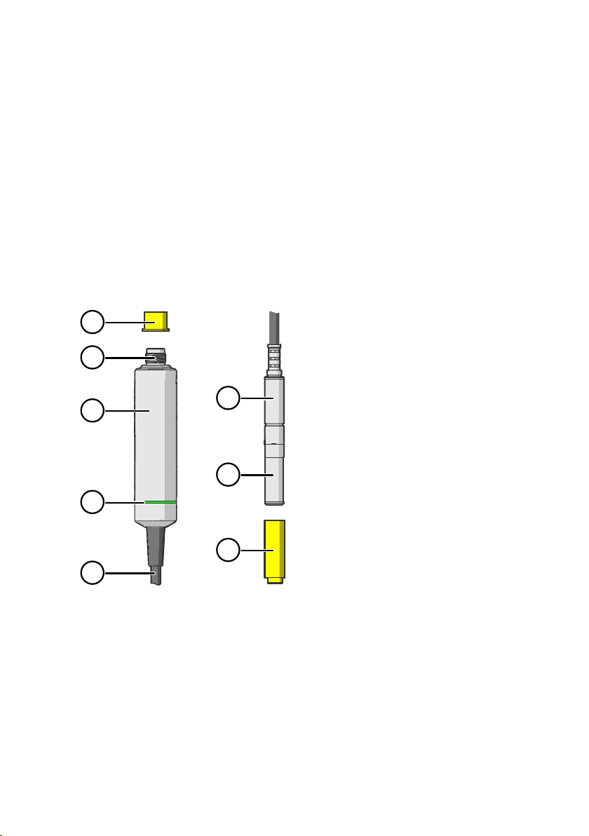
Figure 1 Probe parts
1 Protection cap (remove before use)
2 5-pin M12 connector
3 Probe body with type label
4 Status indicator:
Green Power on and probe online,
Red Error
O Power o or indicator
5 Probe cable (do not cut)
6 Probe head (HMP7 model shown)
7 Location of sensor(s) on the probe
head. Most probe models have a
removable filter over the sensors that
can be replaced if it gets dirty or
damaged. Note that HMP9 and TMP1
do not have a removable filter.
8 Protection cap (remove before use)
flashes when communicating
disabled
2.2 Basic features and options
• Comprehensive list of output parameters. For example: relative humidity, temperature,
dew point temperature, wet-bulb temperature, absolute humidity, mixing ratio, water
vapor pressure, enthalpy. See Output parameters (page 10).
• Sensor purge provides superior chemical resistance (HMP models only)
• Probe and sensor warming functions minimize condensation on probe (HMP models only)
9
Page 12
HMP3, HMP4, HMP5, HMP7, HMP8, HMP9, MMP8, TMP1 User Guide M212022EN-D
• Traceable calibration certificate:
• HMP and MMP models: 6 points for humidity, 1 point for temperature
• TMP1: 2 points for temperature
• Standalone Modbus RTU over RS-485
• Compatible with Indigo series of transmitters
• Can be connected to Vaisala Insight PC software for configuration, calibration,
diagnostics, and temporary online monitoring
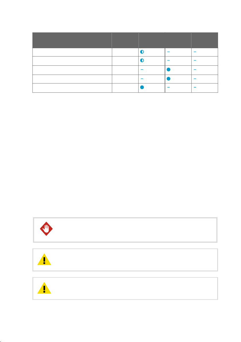
2.3 Output parameters
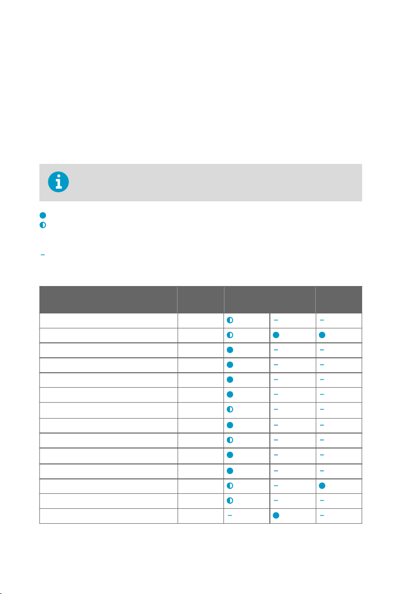
On HMP probe models, the values of all available output parameters are always
locked when chemical purge or extra heat functions are heating the sensor.
Output parameter is available
Output parameter is available but its value is locked during sensor warming or probe
heating (HMP7 only) unless temperature is written to register 0334
source
Output parameter is not available on this model
Table 3 Availability of output parameters
from an external
hex
Output parameter Output unit HMP3, 4, 5,
Relative humidity %RH
Temperature °C
Dew point temperature °C
Dew/frost point temperature °C
Dew/frost point temperature at 1 atm °C
Dew point temperature at 1 atm °C
Absolute humidity
Mixing ratio g/kg
Wet-bulb temperature °C
Water concentration ppm
Water vapor pressure hPa
Water vapor saturation pressure hPa
Enthalpy kJ/kg
Water activity -
10
g/m
3
v
7, 8, and 9
MMP8 TMP1
Page 13
Chapter 2 – Product overview
Output parameter Output unit HMP3, 4, 5,
Dew point temperature dierence °C
Absolute humidity at NTP
Water concentration in oil ppm
Relative saturation %RS
Water mass fraction ppm
g/m
3
v
w
7, 8, and 9
MMP8 TMP1
2.4 Additional features with Indigo 200 series transmitters
Connecting the probe to an Indigo transmitter provides a range of additional options for
outputs, measurement viewing, status monitoring, and configuration interface access.
Examples of additional features available with Indigo 200 series transmitters include:
• 3.5” TFT LCD color display or non-display model with LED indicator
• Digital output or 3 analog outputs (depending on the transmitter model)
• 2 configurable relays
• Wireless browser-based configuration interface for mobile devices and computers (IEEE
802.11 b/g/n WLAN)
The selection of available additional features (for example, output and connectivity options)
varies depending on the Indigo transmitter model. For more information on Indigo
transmitters, see www.vaisala.com/indigo.
2.5
Safety
WARNING!
has not been exposed to dangerous contamination, and is safe to handle
without special precautions.
CAUTION!
serviceable parts inside the probe body.
CAUTION!
deposit impurities on the probe head.
When returning a product for calibration or repair, make sure it
Do not attempt to open the probe body. There are no user
Do not touch the probe head with your bare hands. Touching will
11
Page 14

HMP3, HMP4, HMP5, HMP7, HMP8, HMP9, MMP8, TMP1 User Guide M212022EN-D
CAUTION!
functions such as chemical purge and probe heating are active.
Be aware that the probe head may become hot to touch when
2.6 ESD protection
Electrostatic discharge (ESD) can cause immediate or latent damage to electronic circuits.
Vaisala products are adequately protected against ESD for their intended use. However, it is
possible to damage the product by delivering an electrostatic discharge when touching,
removing or inserting any objects inside the equipment housing.
Avoid touching component contacts or connectors when working with the device.
2.7 Regulatory compliances
The probes are in conformity with the provisions of the following EU directives:
• RoHS Directive
• EMC Directive
Conformity is shown by compliance with the following standards:
• EN 50581: Technical documentation for the assessment of electrical and electronic
products with respect to the restriction of hazardous substances.
• EN 61326-1: Electrical equipment for measurement, control, and laboratory use – EMC
requirements – intended for use in industrial locations.
• EN 55032: Information technology equipment – Radio disturbance characteristics – Limits
and methods of measurement.
2.7.1 FCC Part 15 compliance statement
This equipment has been tested and found to comply with the limits for a Class B digital
device, pursuant to Part 15 of the FCC rules. These limits are designed to provide reasonable
protection against harmful interference in a residential installation. This equipment generates,
uses and can radiate radio frequency energy and, if not installed and used in accordance with
the instructions, may cause harmful interference to radio communications. However, there is
no guarantee that the interference will not occur in a particular installation. If this equipment
does cause harmful interference to radio or television reception, which can be determined by
turning the equipment o and on, the user is encouraged to try to correct the interference by
one or more of the following measures:
• Reorient or relocate the receiving antenna.
• Increase the separation between the equipment and receiver.
• Connect the equipment into an outlet on a circuit dierent from that of the receiver.
• Consult the dealer or an experienced radio/TV technician for help.
12
Page 15

Chapter 2 – Product overview
CAUTION!
by the party responsible for compliance could void the user's authority to
operate the equipment.
Changes or modifications to this equipment not expressly approved
2.7.2 Canada ICES-003 compliance statement
This Class B digital apparatus complies with Canadian ICES‑003.
Cet appareil numerique de la classe B est conforme a la norme NMB‑003 du Canada.
13
Page 16
1
2
3
4
HMP3, HMP4, HMP5, HMP7, HMP8, HMP9, MMP8, TMP1 User Guide M212022EN-D
3. Installation
When you choose the installation location for the probe, consider the following:
• Verify the operating environment specification of the probe model. The probe head
typically has a much wider operating temperature range than the probe body.
• If the temperature of the measured environment diers greatly from ambient
temperature, the entire probe head and preferably plenty of cable must be inside the
measured environment. This prevents measurement inaccuracy caused by heat
conduction along the cable.
• Probe mounting options are model-specific.
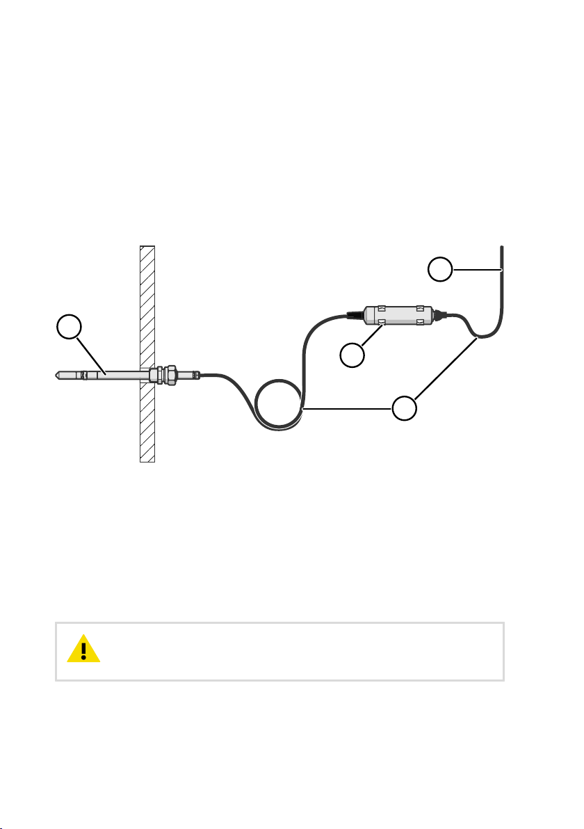
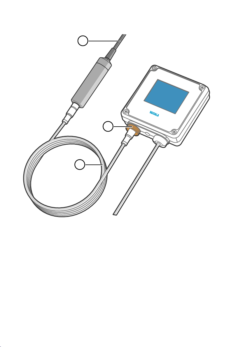
Figure 2 Example installation
Mount the probe head horizontally to prevent any water condensing on the probe head
1
from running to the sensors.
2 Let the cable hang loosely to prevent condensed water from running along the cable to
the probe body or probe head.
3 Attach the probe body to a wall or other surface using the two mounting clips (Vaisala
item 243257SP) supplied with the probe. Each clip attaches to the installation surface with
one screw (screw hole Ø 4.2 mm).
4 Cable to Modbus master or Indigo transmitter.
CAUTION!
vibration. Use other methods to secure the probe body if necessary. For
example, attach the probe body using a cable tie.
The supplied mounting clips are not designed to withstand strong
More information
‣
Default communication settings (page 77)
14
Page 17
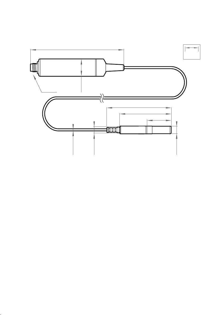
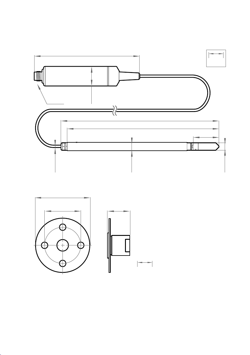
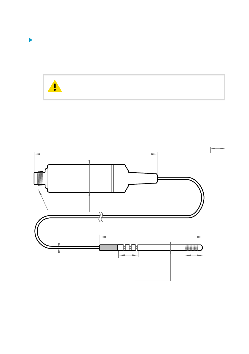
3.1 HMP3 probe
136 [5.35]
Probe cable 2 m [6.56 ft]
Ø 25
[0.98]
M12/5
98.5 [3.88]
78.5 [3.09]
37.5 [1.48]
Ø 5
[0.2]
Ø 12
[0.47]
M9x1
mm
[in]
Figure 3 HMP3 probe dimensions
Chapter 3 – Installation
Vaisala HUMICAPâ Humidity and Temperature Probe HMP3 is a general purpose probe
designed for various industrial processes. The probe structure allows for replacing the sensor
without tools, making it suitable for applications such as paint booths and other industrial
applications where periodic recalibration alone is not sucient for maintaining the probe
performance. Other suitable applications include, for example, industrial HVAC systems,
cleanrooms, and environmental chambers.
• Operating temperature for probe head −40 … +120 °C (−40 … +248 °F)
• Operating temperature for probe body −40 … +80 °C (−40 … +176 °F)
If purchased with a composite sensor instead of the field replaceable HUMICAPâ R2 sensor,
HMP3 can use the chemical purge feature. In environments with high concentrations of
chemicals and cleaning agents, the chemical purge option helps to maintain measurement
accuracy between calibration intervals.
15
Page 18
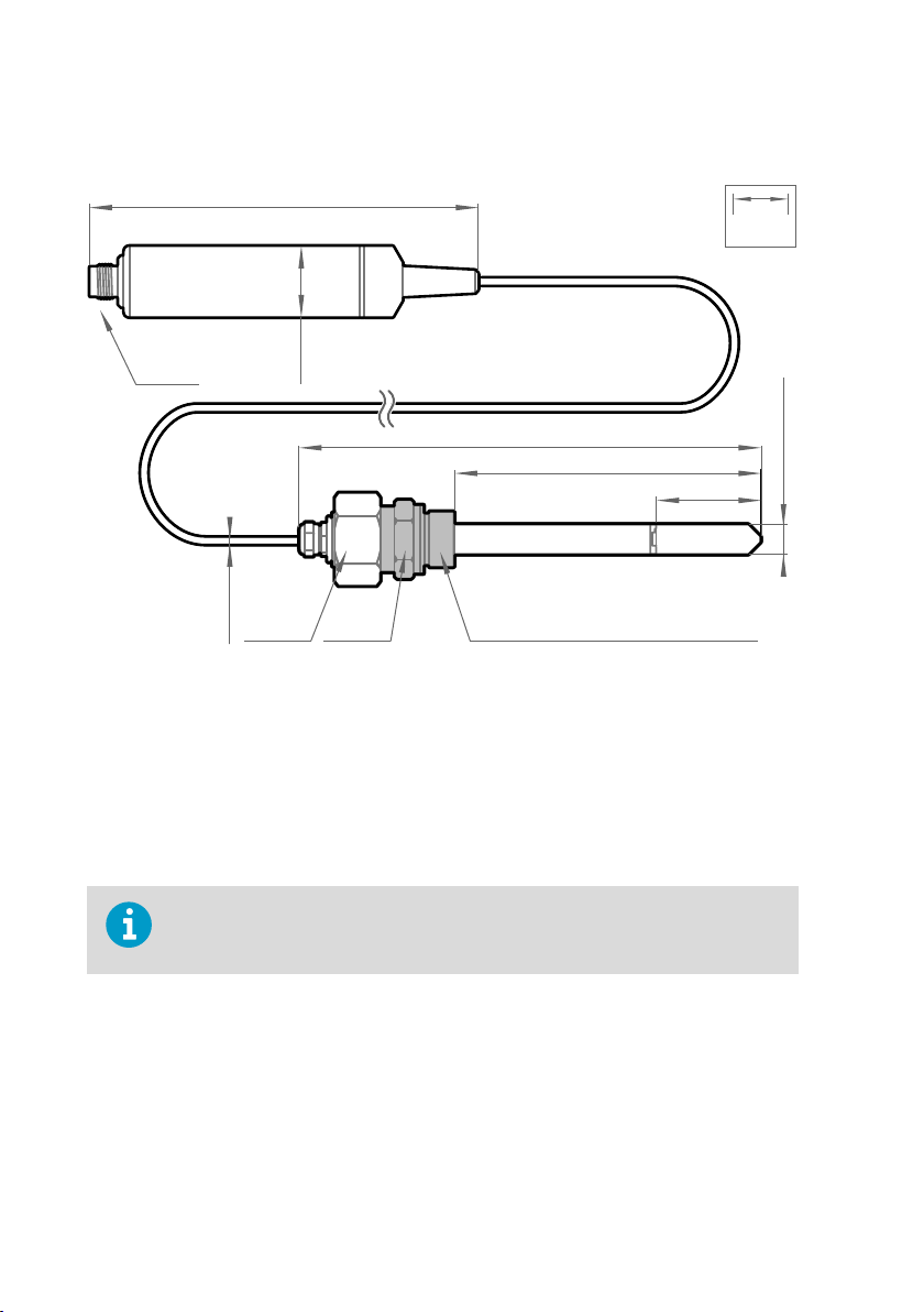
136 [5.35]
Probe cable 2 m [6.56 ft]
Ø 25
[0.98]
M12/5
183 [7.20]
120 [4.72]
41 [1.61]
Ø 5
[0.2]
Fitting body NPT1/2” or M22×1.5
with sealing ring Ø22×27×1.5 Cu
Ø 12
[0.47]
32 mm 27 mm
mm
[in]
HMP3, HMP4, HMP5, HMP7, HMP8, HMP9, MMP8, TMP1 User Guide M212022EN-D
3.2 HMP4 probe
Figure 4 HMP4 probe dimensions
Vaisala HUMICAPâ Humidity and Temperature Probe HMP4 is designed for high-pressure
applications such as compressed air systems in maritime, breathing air, and industrial
applications, where measurement performance and chemical tolerance are essential.
• Temperature measurement range −70 … +180 °C (−94 … +356 °F)
• Operating pressure 0 … 10 MPa (0 … 100 bar)
• Operating temperature for probe body −40 … +80 °C (−40 … +176 °F)
• M22×1.5 or NPT1/2” fitting body
Use a sealing ring (Ø22×27×1.5 Cu) with the M22×1.5 fitting. Replace the sealing
ring every time the probe is detached. Three sealing rings are supplied with the
fitting.
16
Page 19
3.3 HMP5 probe
136 [5.35]
Ø 25
[0.98]
M12/5
41 [1.61]
253 [9.96]
243 [9.57]
Ø 12
[0.47]
Ø 13.5
[0.53]
Probe cable
2 m [6.56 ft] or 10 m [32.8 ft]
Ø 5
[0.2]
mm
[in]
mm
[in]
75 [2.95]
50 [1.96] 19 [0.75]
Figure 5 HMP5 probe dimensions
Chapter 3 – Installation
Figure 6 Optional mounting flange 210696 dimensions
Vaisala HUMICAPâ Humidity and Temperature Probe HMP5 is designed for high-temperature
applications such as baking ovens, pasta dryers, and industrial drying kilns, where
measurement performance and chemical tolerance are essential.
• Temperature measurement range −70 … +180 °C (−94 … +356 °F)
17
Page 20
mm
[in]
136 [5.35]
Ø 25
[0.98]
M12/5
Ø 12
[0.47]
99.5 [3.92]
79.5 [3.13]
37.5 [1.48]
Groove for
lock ring
Ø 12
[0.47]
Ø 5
[0.2]
Probe cable
2 m [6.56 ft] or 10 m [32.8 ft]
HMP3, HMP4, HMP5, HMP7, HMP8, HMP9, MMP8, TMP1 User Guide M212022EN-D
• Operating temperature of probe body −40 … +80 °C (−40 … +176 °F)
• 250-mm (9.84 in) probe allows easy process installation through insulation
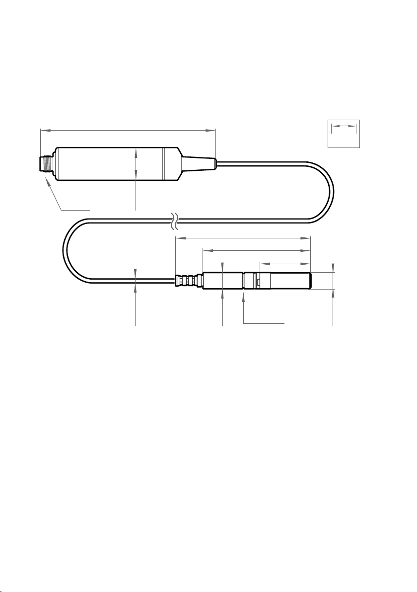
3.4 HMP7 probe
Figure 7 HMP7 probe dimensions
Vaisala HUMICAPâ Humidity and Temperature Probe HMP7 is designed for applications that
involve constant high humidity or rapid changes in humidity, such as drying and test
chambers, combustion air, and other humidifiers and meteorological measurements, where
measurement performance and chemical tolerance are essential.
Probe heating
HMP7 supports probe heating. Probe heating heats up not only the sensor, but the entire
probe head. When probe temperature is heated above dew point temperature, condensation
on the probe can be avoided while measuring the dew point temperature of the process.
• Temperature measurement range −70 … +180 °C (−94 … +356 °F)
• Operating temperature of probe body −40 … +80 °C (−40 … +176 °F)
• Probe heating and sensor warming functions minimize condensation on probe
• Vapor and pressure proof construction
18
Page 21
136 [5.35]
Probe cable 2 m [6.56 ft]
Ø 25
[0.98]
M12/5
Ø 12
[0.47]
41 [1.61]
Ø 13.5
[0.53]
Fitting body
ISO1/2” or NPT1/2”
Ø 5
[0.2]
mm
[in]
268 [10.55]
230 [9.06]
41 ... 185 [1.16 ... 7.28]
Chapter 3 – Installation
If probe heating is enabled, output parameters that are dependent on temperature
measurement (such as relative humidity) are locked whenever probe is heated unless the true
temperature of the measured environment is updated to the temperature compensation
register of the probe from another measurement instrument (for example, the TMP1 probe).
Output parameters such as dew point temperature that can be measured or calculated
without this external temperature information are available even without the temperature
input.
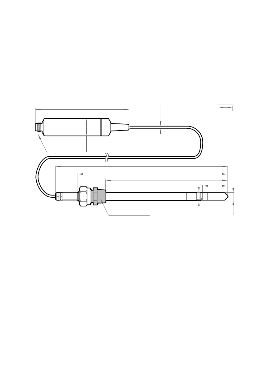
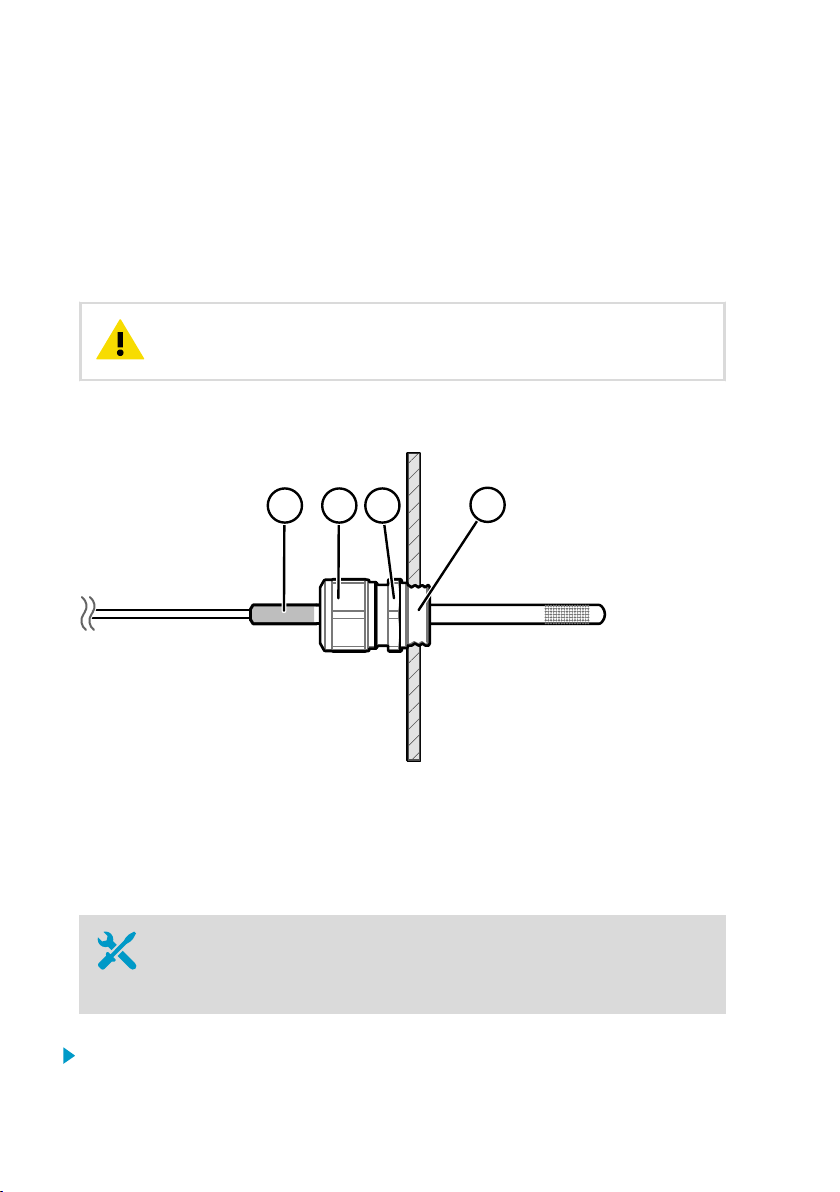
3.5 HMP8 probe
Figure 8 HMP8 probe dimensions
Vaisala HUMICAPâ Humidity and Temperature Probe HMP8 is designed for pressurized
applications in compressed air systems, refrigerant dryers, and other pressurized industrial
applications, where easy insertion and removal of the probe and adjustable installation depth
into the pipeline are needed.
• Temperature measurement range −70 … +180 °C (−94 … +356 °F)
• Operating temperature of probe body −40 … +80 °C (−40 … +176 °F)
• Operating pressure 0 … 4 MPa (0 … 40 bar)
• Probe installation depth can be freely adjusted and probe can be hot-swapped from
pressurized pipelines with an installation valve
• ISO1/2" or NPT1/2" fitting body
19
Page 22
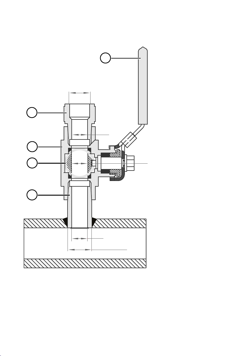
G1/2
ISO 228/1
Ø21.5 (drilling)
Ø14
Ø14
Ø14
2
3
4
5
1
HMP3, HMP4, HMP5, HMP7, HMP8, HMP9, MMP8, TMP1 User Guide M212022EN-D
3.5.1 Attaching ball valve kit to process
1 Ball valve handle: must point to the same direction as the ball valve body when installing.
2 Extension nipple, threads G1/2 ISO228/1 and R1/2 ISO7/1.
3 Ball valve body. When tightening the assembly, turn only from the ball valve body.
4 Ball of the ball valve.
5 Welding joint, threads R1/2 ISO7/1.
20
Page 23
mm
[in]
112 [4.41]
Probe cable 2 m [6.56 ft]
Ø 25
[0.98]
M12/5
94 [3.70]
Ø 2.4
[0.094]
Ø 5 ±0.05
[0.20 ±0.002]
16 [0.63]
Attachment point
Chapter 3 – Installation
1. Attach the welding joint to the process pipe or chamber.
2. Apply a sealant (MEGA-PIPE EXTRA No. 7188 or LOCTITEâ No. 542 with activator No.
7649) on the threads of the welding joint and screw the bottom of the ball valve onto the
welding joint.
3. Tighten the ball valve assembly by turning from the ball valve body.
CAUTION!
can break the sealing. Tighten the ball valve assembly only from the ball
valve body.
4. If you need to cap the ball valve assembly before installing or after removing the probe,
attach a blanking nut to close the top of the valve.
3.6
HMP9 probe
Tightening the ball valve kit by turning the extension nipple
Figure 9 HMP9 probe dimensions
Vaisala HUMICAPâ Humidity and Temperature Probe HMP9 is designed for easy installation
into rapidly changing environments where fast response time, measurement performance, and
chemical tolerance are essential.
21
Page 24
1 2 3
4
HMP3, HMP4, HMP5, HMP7, HMP8, HMP9, MMP8, TMP1 User Guide M212022EN-D
The probe head can be mounted through thin metal walls using the included cable gland or
mounting grommet. Two grommets are included: small one for 6.5 mm diameter hole, and
large one for 12.5 mm diameter hole.
You can also attach the probe head directly using a zip tie. The probe head should be attached
from the point near the black plastic part.
• Temperature measurement range −40 … +120 °C (−40 … +248 °F)
• Operating temperature of probe body −40 … +60 °C (−40 … +140 °F)
• Integrated filter (non-replaceable)
CAUTION!
Avoid overtightening when installing the probe head through a cable gland.
Do not damage the probe head by bending, crushing, or striking it.
3.6.1 Installing HMP9 through a cable gland
Figure 10 Installing HMP9 probe head through a cable gland
Black plastic part of the HMP9 probe head
1
2 Nut for tightening the probe in place
3 Base of the cable gland
4 M10×1.5 threads of the cable gland
• M10×1.5 cable gland (included with HMP9 probe)
• Drill with 8.5 mm bit
• M10×1.5 threading tap
• 13 mm wrench
1. Drill a 8.5 mm diameter hole in the installation location.
22
Page 25
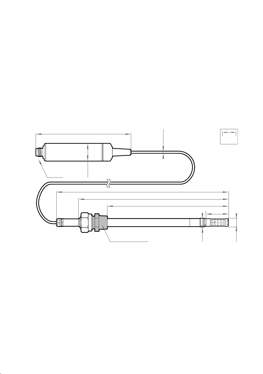
136 [5.35]
Probe cable 2 m [6.56 ft]
Ø 25
[0.98]
M12/5
Ø 5
[0.2]
mm
[in]
262 [10.32]
224 [8.82]
35 ... 179 [1.37 ... 7.05]
35 [1.37]
Ø 13.5
[0.53]
Fitting body
ISO1/2” or NPT1/2”
Ø 12
[0.47]
Chapter 3 – Installation
2. Use a threading tap to create a M10×1.5 thread in the hole.
3. Install the base of the cable gland in the hole and tighten with a 13 mm wrench.
4. Insert the seal of the cable gland in the base and place the nut of the cable gland over the
probe head.
5. Insert the probe head in the cable gland up to the black plastic part of the probe head.
Leave the black plastic part entirely outside the cable gland. Tighten the cable gland to
finger tightness.
6. Tighten the nut of the cable gland with a 13 mm wrench until the probe head stops
moving. Do not overtighten.
3.7 MMP8 probe
Figure 11 MMP8 dimensions
Vaisala HUMICAPâ Moisture in Oil Probe MMP8 enables fast and reliable measurement of
moisture in oil. It uses proven Vaisala HUMICAPâ sensor that was developed for demanding
dissolved moisture measurements in transformer and lubrication oils, hydraulic fluids, and
other liquids.
MMP8 measures dissolved moisture in oil in terms of the water activity (aw), relative saturation
(%RS), and temperature (T). Water activity or relative saturation indicate directly whether
there is a risk of free water formation. This data is relevant in lubrication oil applications where
detecting water ingress and preventing free water formation is crucial. The measurement is
independent of oil type and age.
23
Page 26
130 [5.12]
Ø 6
[0.24]
136 [5.35]
Ø 25
[0.98]
M12/5
Ø 3.2
[0.13]
mm
[in]
Probe cable
2 m [6.56 ft] or 10 m [32.8 ft]
HMP3, HMP4, HMP5, HMP7, HMP8, HMP9, MMP8, TMP1 User Guide M212022EN-D
MMP8 can also output ppm, the average mass concentration of water in oil. Vaisala has this
conversion readily available for specific oils, including mineral transformer oil. This allows
continuous measurement of ppm concentration in power transformer condition monitoring.
• Temperature measurement range −40 … +180 °C (−40 … +356 °F)
When installed with the ball valve kit, the MMP8 is ideal for installation into processes where
the probe needs to be installed or removed while the process is running. Probe installation
depth is adjustable. Pressure fitting options are ISO 1/2" and NPT 1/2". MMP8 is delivered with
a manual pressing handle that allows the probe to be pushed against process pressure.
For installation instructions of the ball valve see Attaching ball valve kit to process (page 20).
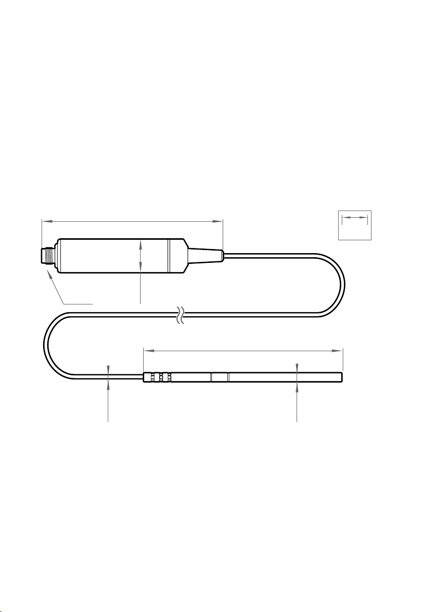
3.8 TMP1 probe
Figure 12 TMP1 probe dimensions
Vaisala Temperature Probe TMP1 is designed for demanding temperature measurements in
industrial applications such as pharmaceutical industry and calibration laboratories, where
accuracy and robustness are essential.
• Temperature measurement range −70 … +180 °C (−94 … +356 °F)
• Operating temperature of probe body −40 … +80 °C (−40 … +176 °F)
24
Page 27
1
534
2
RS-485 host
DC power supply
RS-485 +
RS-485 -
RS-485 common
+
-
Pin #1
Power supply
Pin #2
RS-485 -
Pin #3
Power GND
RS-485 common
Pin #4
RS-485 +
Pin #5
Probe
Chapter 3 – Installation
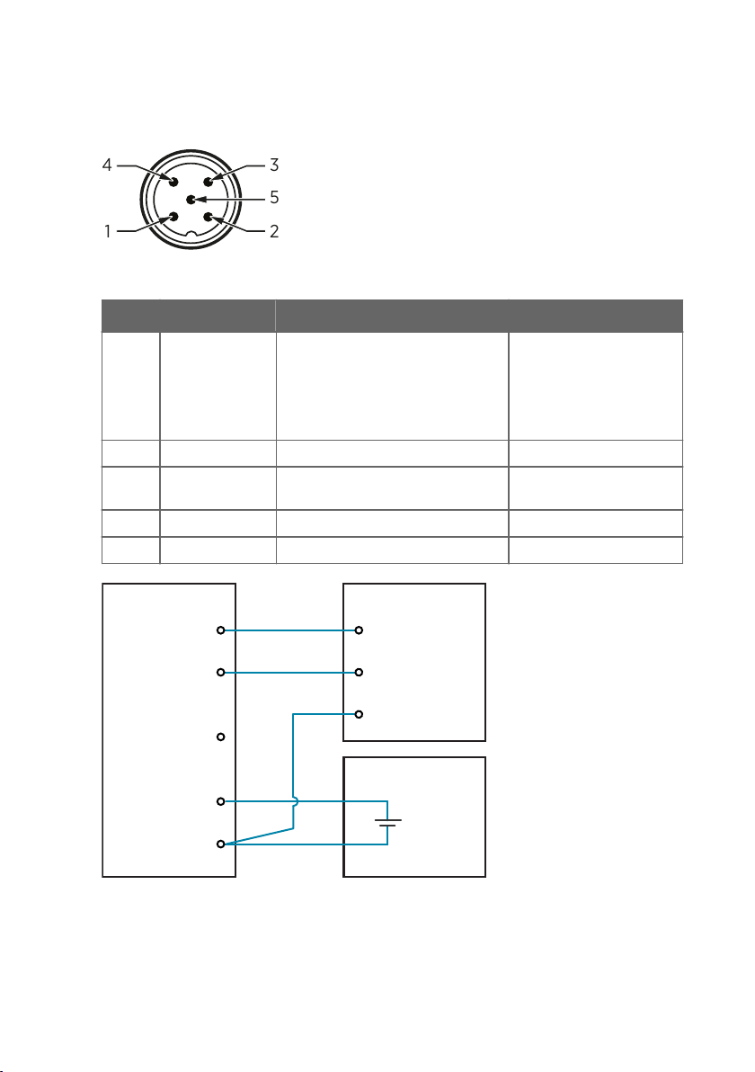
3.9 Wiring
Figure 13 M12 5-pin A-coded male connector pinout
Pin # Function Notes Wire colors in Vaisala cables
1 Power supply Operating voltage:
• HMP7: 18 ... 30 VDC
• Other models: 15 ... 30 VDC
Current consumption: 10 mA typical,
500 mA max.
2 RS-485 - White
3 Power GND and
Blue
RS-485 common
4 RS-485 + Black
5 Not connected Gray
Brown
Figure 14 RS-485 wiring
25
Page 28

HMP3, HMP4, HMP5, HMP7, HMP8, HMP9, MMP8, TMP1 User Guide M212022EN-D
Recommended maximum length of the RS-485 line is 30 m (98 ft).
26
Page 29

Chapter 4 – Configuration with Insight software
4. Configuration with Insight software
4.1 Vaisala Insight software
Vaisala Insight software is a configuration software for Indigo-compatible devices. With the
Insight software, you can:
• See probe information and status
• See real-time measurement
• Record data up to 48 hours and export in CSV format
• Calibrate and adjust the probe
• Configure probe features such as measurement filtering, chemical purge, heating, and
serial communication
Microsoft Windowsâ operating system and Vaisala USB cable (no. 242659) required.
Download Vaisala Insight software at www.vaisala.com/insight.
4.2
Installing driver for the USB service cable
Only Windowsâ operating systems are supported by the driver of the USB
service cable.
1. Connect the USB service cable to a USB port on your computer. Windowsâ detects the
new device and installs the appropriate driver.
2. Open Devices and Printers from the Windowsâ Start menu. Use search to find it if
necessary (search for "devices").
27
Page 30

HMP3, HMP4, HMP5, HMP7, HMP8, HMP9, MMP8, TMP1 User Guide M212022EN-D
3. Locate the cable in the list of devices:
• If the device is listed as Vaisala USB Device with a COM port number in brackets, the
cable is ready for use. Note the COM port number, you will need it later.
• If the device is listed as Vaisala USB Instrument Cable without a COM port number
listed, you must install the driver manually.
4. To install the driver manually:
a. Disconnect the USB service cable from the computer.
b. Download the Vaisala USB driver at http://www.vaisala.com/software (select the
appropriate USB Instrument Driver Setup for your cable).
c. Run the USB driver installation program Vaisala USB Device Driver
Setup.exe. Accept the installation defaults.
d. Go back to step 1 and verify that the driver installation works as expected.
4.3
Connecting to Insight software
• Computer with Microsoft Windowsâ operating system and Vaisala Insight
software installed
• USB connection cable (no. 242659)
CAUTION!
computer may not be able to supply enough power through its USB ports. Use
an externally powered USB hub that can supply >2 W for each port.
28
When connecting several devices at the same time, note that your
Page 31

Chapter 4 – Configuration with Insight software
Figure 15 Connecting probe to Insight
1. Open Insight software.
2. Connect the USB cable to a free USB port on the PC or USB hub.
3. Connect the probe to the USB cable.
4. Wait for Insight software to detect the probe.
4.4
Configuration options
Select > Configure Device to access configuration options in Insight software.
Available configuration options include all of the Modbus configuration registers (see
Configuration registers (page 82)) and several additional options. Insight software is the
recommended way to change the probe configuration.
You can restore the probe back to its default settings using the Factory Default
Settings > Restore Settings function. Doing this will also clear any user
adjustment and restore the latest factory calibration.
29
Page 32

HMP3, HMP4, HMP5, HMP7, HMP8, HMP9, MMP8, TMP1 User Guide M212022EN-D
Figure 16 HMP5 in Insight software
30
Page 33

1
2
3
4
5
6
Chapter 5 – Using probe with Indigo transmitters
5. Using probe with Indigo transmitters
5.1 Indigo 200 series transmitter overview
Figure 17 HMP7 attached to Indigo 200 series transmitter
3.5” TFT LCD color display: non-display option with LED available for certain models
1
2 Locking wheel: insert probe, hold in place, and turn the wheel counterclockwise
3 Cable to probe head
4 Wireless configuration interface (WLAN) activation button
5 Rubber lead-through with strain relief. Cable feedthrough option also at back of
transmitter.
6 Input/output cable
31
Page 34
1
2
3
HMP3, HMP4, HMP5, HMP7, HMP8, HMP9, MMP8, TMP1 User Guide M212022EN-D
Figure 18 HMP7 attached to Indigo 200 series transmitter with a cable
Cable to probe head
1
2 Locking wheel: insert cable, hold in place, and turn the wheel counterclockwise
3 Connection cable
The probe can be connected to Vaisala Indigo transmitters, either directly on the transmitter
from the probe's connector, or by using a cable between Indigo and the probe.
Indigo transmitters are host devices that extend the feature set of connected probes with a
range of additional options for outputs, configuration access, measurement viewing, and
status monitoring.
The selection of available additional features (for example, output and connectivity options)
varies depending on the Indigo transmitter model. Depending on the model, a display is
available as an optional selection or as a standard feature. In the non-display model, an LED
indicator is used for notifications.
32
Page 35

Chapter 5 – Using probe with Indigo transmitters
5.2 Attaching probe to Indigo 200 series transmitter
Figure 19 Attaching the probe to Indigo 200 series transmitter
1. Insert the probe or the connection cable into the transmitter's connector. Use of
connection cable is recommended for strain relief.
2. Turn the locking wheel of the transmitter to lock the probe or cable in place.
Do not turn the probe or the cable itself, as that will damage the connectors.
3. If you are using a connection cable, connect the probe to the cable.
4. When the transmitter recognizes the connected probe, it shows a notification message on
the display.
33
Page 36

19.75
%RH
RH
-3.50
°C
T
19.88
°C
T
WLAN is activated
Indigo 201
d/f
Select WLAN to connect to:
1. WLAN XYZ
3. WLAN ABC
2. Indigo_ID[xx]
1 2 3
HMP3, HMP4, HMP5, HMP7, HMP8, HMP9, MMP8, TMP1 User Guide M212022EN-D
5.3 Wireless configuration interface overview
The wireless configuration interface has two user levels:
• All users have view-only access (no configuration rights, not password protected).
• Personnel that carry out configuration tasks can log in with an administrative password
that allows changing the transmitter and probe settings.
To use the wireless configuration interface to modify the settings of your Indigo transmitter
and the connected probe, you must first enable the transmitter's wireless connection and then
connect to Indigo with your mobile device or computer. Most major browsers (for example,
Firefox, Chrome, Safari, and Internet Explorer) are supported: using the most recent version is
recommended.
5.4 Connecting to wireless configuration interface
Figure 20 Enabling and accessing wireless configuration interface of Indigo 200
Wireless connection activation button
1
2 Wireless connection indicator (WLAN symbol) on the Indigo display
3 Choose Indigo (Indigo_ID[xx]) from your wireless device's list of available connections
34
Page 37

Chapter 5 – Using probe with Indigo transmitters
5.5 Logging in to wireless configuration interface
Figure 21 Indigo login view
When you open Indigo's wireless configuration interface in your browser, you are prompted to
log in. There are 2 available user levels:
• User: view-only access available for all users. Does not require a password.
• Admin: password-protected access. To change settings, you must log in as admin.
To log in:
1. Enter the user name and password:
a. To log in as user (view-only access, no configuration rights), select User from the
User name dropdown. Leave the Password field empty.
b. To log in as admin (required for configuration), select Admin in the User name
dropdown and type the admin password (default: 12345) in the Password field.
2. Select Log in after entering the login credentials. The wireless configuration interface
opens in the Measurements view.
The user level (User or Admin) is shown in the upper right corner of all menu
views.
Select the user/admin icon in the upper right corner to change the user level.
35
Page 38

HMP3, HMP4, HMP5, HMP7, HMP8, HMP9, MMP8, TMP1 User Guide M212022EN-D
6. Maintenance
6.1 Cleaning the probe
Do not attempt to clean the sensors under the filter in any way.CAUTION!
Do not spray anything directly on the probe head, since that may deposit
impurities on the sensors.
You can clean the probe, probe body, and cable by wiping them with a soft, lint-free cloth
moistened with water or a suitable cleaning agent, such as isopropyl alcohol. Do not wipe the
filter: wiping the filter may block its pores and/or deposit residue on the filter. If the filter is
heavily contaminated, replace it.
When cleaning, follow these precautions:
• Avoid touching the filter. If you need to touch the filter, always wear clean gloves (cotton,
rubber or similar material). Keep the filter free of any grease or oil.
• Do not scrape the probe or the probe body.
• Do not immerse the probe or the probe body in liquid to clean them.
• Wipe cleaning agents o the probe, probe body, and the cable after cleaning.
After cleaning the probe, it is recommended to perform a chemical purge.
6.1.1 Chemical tolerance
Avoid exposing the probe to cleaning agents for unnecessarily long periods of
time.
Table 4 Suitability of cleaning agents
Cleaning Agent Suitability
Acetone Suitable
Chlorine disinfectants Suitable
Ethanol Suitable
Heptane Suitable
Isopropyl alcohol Suitable
36
Page 39

6.2 Changing the probe filter
• New compatible filter
• Clean lint-free gloves
Chapter 6 – Maintenance
CAUTION!
the probe head carefully.
HMP9 and TMP1 probe models do not have a removable filter.
1. Put on clean gloves before touching the filter.
2. Turn the filter counter-clockwise to loosen it.
3. Remove the filter from the probe head. Be careful not to touch the sensors with the filter.
4. Install a new filter on the probe head. Tighten the filter properly (recommended force
5 Nm).
6.3
Replacing the HUMICAP R2 sensor
• New HUMICAPâ R2 sensor
• New compatible filter
• Clean lint-free gloves
• 11.3 %RH and 75.5 %RH humidity references (using Vaisala HMK15 Humidity
Calibrator)
• Computer with Microsoft Windowsâ operating system and Vaisala Insight
software installed
• USB connection cable (no. 242659)
Sensors are easily damaged when the filter is not in place. Handle
Follow this procedure to replace a HUMICAPâ R2 humidity sensor it has been damaged, or
normal adjustment is not sucient to restore the humidity measurement accuracy. It is
recommended that you replace the filter at the same time. The procedure includes a special 2point adjustment of humidity measurement using Insight PC software. This adjustment must
be done every time after the HUMICAPâ R2 sensor has been replaced.
37
Page 40

2
1
HMP3, HMP4, HMP5, HMP7, HMP8, HMP9, MMP8, TMP1 User Guide M212022EN-D
CAUTION!
user. Other humidity sensor types available for HMP series probes are composite
sensors where the humidity sensor and temperature sensor are permanently
attached together. If you need to replace a composite sensor, contact a Vaisala
Service Center.
CAUTION!
the probe head carefully.
CAUTION!
entered in this procedure. If you need to revert the probe to factory settings
after replacing the sensor yourself, write down the values on the Adjustment
data page beforehand, and enter them again after applying the factory settings.
Only the HUMICAPâ R2 sensor is designed to be replaced by the
Sensors are easily damaged when the filter is not in place. Handle
Reverting the probe to factory settings clears the adjustment values
Figure 22 HMP3 probe head with filter removed
Pt100 temperature sensor
1
2 HUMICAPâ R2 humidity sensor
1. Put on clean gloves before touching the filter.
2. Turn the filter counter-clockwise to loosen it.
3. Remove the filter from the probe head. Be careful not to touch the sensors with the filter.
4. There are two sensors under the filter, the HUMICAPâ sensor and a temperature sensor.
Identify the HUMICAPâ sensor and make sure it is of the R2 type (temperature sensor not
attached to it).
38
Page 41

5. Pull out the old HUMICAPâ R2 sensor and insert the new one.
Chapter 6 – Maintenance
CAUTION!
sensor element in the middle of the sensor. Do not touch the temperature
sensor.
6. Open Insight software.
7. Select Settings > Advanced Mode.
8. Connect the probe to Insight. See Connecting to Insight software (page 28).
9. Select
10. Select Adjustment data.
11. Adjust the 11.3 %RH point (dry end):
12. Adjust the 75.5 %RH point (wet end):
13. Click outside the table to commit the adjustment.
14. Remove the probe head from the calibration reference and install a new filter. Tighten the
filter properly (recommended force 5 Nm).
15. Select the Calibration information tab and update the Calibration date and Calibration
text.
16. Select Close > Yes to exit the calibration mode.
> Calibrate > Yes to switch the probe to calibration mode.
a. Insert the probe head in the 11.3 %RH reference.
b. Wait for the measurement to stabilize fully.
c. Click table cell A1 under RH adjustment data and enter the value of the humidity
reference (11.3).
d. Click table cell B1 and enter the %RH measured by the probe.
a. Insert the probe head in the 75.5 %RH reference.
b. Wait for the measurement to stabilize fully.
c. Click table cell A2 and enter the value of the humidity reference (75.5).
d. Click table cell B2 and enter the %RH measured by the probe.
Handle the new sensor by the plastic frame. Do not touch the
6.4
Calibration and adjustment
The probe is fully calibrated and adjusted as shipped from the factory. To maintain the
accuracy of the measurement, calibrate and adjust the probe as needed. Typical calibration
interval is one year, but depending on the application it may be necessary to check the
accuracy more frequently.
When adjustment is necessary, you can have Vaisala calibrate and adjust the probe. To order
calibration services from Vaisala, visit store.vaisala.com. You can also do the adjustment
yourself using the Insight software.
39
Page 42

HMP3, HMP4, HMP5, HMP7, HMP8, HMP9, MMP8, TMP1 User Guide M212022EN-D
WARNING!
has not been exposed to dangerous contamination, and is safe to handle
without special precautions.
If you think the device is not measuring correctly, calibration and adjustment is
not the first thing to do. Check the following first:
• Make sure nothing is interfering with the measurement: heat sources,
temperature dierences, or condensation.
• Check that there is no moisture on the probe. If the sensor has become wet,
wait for it to dry.
• Always wait for the measurement to stabilize.
Calibration means comparing the measurement output of the device to a known
reference, such as a known environment in a calibration chamber or the output of
a reference instrument. Correcting the reading of the device so that it measures
accurately is referred to as adjustment.
When returning a product for calibration or repair, make sure it
6.4.1 Adjustment points and requirements
You can adjust the humidity measurement in 1 ... 5 points, and temperature measurement in 1 ...
2 points. Note the following:
• Humidity adjustment in more than two points is available when using Insight software in
Advanced Mode.
• If you are adjusting in more than one humidity point, make sure the first two points are at
least 10 %RH apart.
• The probe will reject adjustments that are too large, that is, greater than 10 %RH for
humidity and 0.5 °C for temperature. If the probe appears to need such a large correction,
perform a sensor purge and repeat the adjustment procedure. Make sure the
measurement has stabilized and the reference environment is reliable. If the required
adjustment is still too large, the probe needs to be serviced by Vaisala.
40
When adjustment of humidity measurement is necessary, Vaisala recommends
adjusting in two points, 11 %RH and 75 %RH. These humidities can be produced
using the Vaisala HMK15 Humidity Calibrator.
Adjustment of temperature measurement is typically not necessary.
Page 43

Chapter 6 – Maintenance
6.4.2 Adjusting measurement with Insight software
• Computer with Windows operating system and Vaisala Insight software
installed
• Vaisala USB cable 242659 for connecting the probe
• Reference environment(s) for producing the desired humidity and/or
temperature
This procedure can be used to adjust the probe's humidity or temperature measurement. If you
want to adjust both, repeat the procedure.
Because stabilization of temperature and humidity takes time, you should expect the
adjustment procedure to take at least 30 minutes for each adjustment point.
1. Connect the probe to Insight. See Connecting to Insight software (page 28).
2. If you intend to adjust humidity measurement, first select > Purge to perform a
chemical purge to condition the sensor. Wait a few minutes for purge to complete.
3. Select > Calibrate > Yes to switch the probe to calibration mode.
In calibration mode, the device will not use functions that may interfere with calibration
and adjustment.
4. Select the type of adjustment to perform: RH adjustment or T adjustment.
5. Define the needed adjustment for the first measurement point:
a. Insert the probe head in the reference environment for the first calibration point.
b. Wait for the measurement to stabilize fully.
c. Click the Reference value, point 1 text box and enter the reference value of the
calibration point. Press ENTER or click outside the text box when done.
d. The probe automatically enters the measured values for the calibration point.
6. If you want to adjust in more than one point, repeat step 5 for all desired calibration
points.
You can adjust humidity measurement in up to five points when Insight is set
to Advanced mode.
7. Select Activate adjustment > Yes to store the adjustment in the probe.
8. Check the message that appears at the top of the screen. If the message indicates that
the adjustment is activated successfully, your adjustment is stored in the probe.
9. Select the Calibration information tab and update the Calibration date and Calibration
text.
10. Select Close > Yes to exit the calibration mode.
41
Page 44

HMP3, HMP4, HMP5, HMP7, HMP8, HMP9, MMP8, TMP1 User Guide M212022EN-D
6.4.3 Adjusting measurement with Indigo 200 transmitter
• Indigo 200 transmitter
• Reference environment(s) for producing the desired humidity and/or
temperature (see Adjustment points and requirements (page 40) for more
information)
• Mobile device or computer with an internet browser and a Wi-Fi connection
• Connection cable for connecting the probe to Indigo 200 transmitter
(optional)
This procedure can be used to adjust the humidity or temperature measurement of an Indigocompatible HMP or TMP-series probe. Because stabilization of temperature and humidity takes
time, you should expect the adjustment procedure to take at least 30 minutes for each
adjustment point.
This procedure assumes the Indigo 200 transmitter is powered on and the probe
is connected to it. Refer to the user guide of your Indigo 200 transmitter model
for instructions on connecting probes. The user guide also provides more detailed
instructions for operating and troubleshooting the wireless connection.
1. Connect to the wireless configuration interface of the Indigo 200 transmitter:
a. Press the wireless connection activation button on the bottom of the transmitter.
b. Open the wireless connection menu in your mobile device or computer and select
Indigo_ID[xx] (transmitter-specific SSID) from the list of available connections.
c. If the wireless configuration interface does not launch automatically on your device,
start your browser application manually and navigate to address 192.168.1.1.
d. Log in to the interface:
• User name: Admin
• Password: 12345 (default)
42
Stay close to the transmitter for a strong wireless signal and the possibility to
read on-screen messages from the transmitter's display (display models
only). Starting with Indigo 200 firmware version 1.4.0, messages from the
probe are also shown through the wireless configuration interface.
Page 45

Chapter 6 – Maintenance
2. To adjust humidity measurement:
a. If your probe supports the chemical purge feature, wait for the start-up purge to
finish or start the purge manually from Calibration > Configuration > Purge.
Measurement will be frozen for the duration of the purge. Continue when the
measured values are changing again.
b. Select the Calibration tab and select Start calibration to start the calibration mode.
c. In the RH adjustment section of the page, select Restore factory adjustment to
remove any existing non-factory adjustments.
d. Insert the probe head in the reference environment for RH adjustment point 1 (dry
point, recommendation 0 … 35 %RH).
e. Wait for the RH and temperature measurements to stabilize fully. This may take more
than 30 minutes. Monitor the readings to see when the measurement has stabilized.
f. Enter the value of the first reference into the Reference value, point 1 field. Select
outside the text box when done. The probe automatically enters the measured values
for the calibration point.
g. If you want to adjust humidity measurement in two points, repeat steps
step 2.d … step 2.f for RH adjustment point 2 (wet point, recommendation
65 … 85 %RH).
h. Select Activate adjustment to store the adjustment in the probe.
When the adjustment is successful, the fields for reference and measured
values are cleared. The message %0 adjustment activated successfully.
appears on the local display (display models only).
If the adjustment fails, the fields are not cleared. A message on the
transmitter's display will indicate the reason. For example, if the humidity
adjustment would be over the maximum 10 %RH allowed by the probe,
the message Cumulative adjustment too large. appears on the local
display.
43
Page 46

HMP3, HMP4, HMP5, HMP7, HMP8, HMP9, MMP8, TMP1 User Guide M212022EN-D
Figure 23 Calibration page in the Indigo 200 wireless configuration interface
44
Page 47

Chapter 6 – Maintenance
3. To adjust temperature measurement:
a. If you did not adjust humidity measurement, select the Calibration tab and select
Start calibration to start the calibration mode.
b. In the T adjustment section of the page, select Restore factory adjustment to remove
any existing non-factory adjustments.
c. Insert the probe head in the reference environment for T adjustment point 1.
d. Wait for temperature measurement to stabilize fully. This may take more than 30
minutes. Monitor the reading to see when the measurement has stabilized.
e. Enter the value of the first reference into the Reference value, point 1 field. Select
outside the text box when done. The probe automatically enters the measured value
for the adjustment point.
f. If you want to adjust temperature measurement in two points, repeat steps
step 3.c … step 3.f for T adjustment point 2.
g. Select Activate adjustment to store the adjustment in the probe.
4. In the Calibration information section of the page, update the Calibration date and
Calibration text fields.
5. Select Stop calibration to end the calibration mode.
45
Page 48

HMP3, HMP4, HMP5, HMP7, HMP8, HMP9, MMP8, TMP1 User Guide M212022EN-D
7. Troubleshooting
7.1 Problem situations
Table 5 Troubleshooting table
Problem Possible cause Solution
Measurement output seems
incorrect
Probe status indicator LED is
red
Values of measurement
parameters stop changing for a
few minutes
Installation location is not
representative of actual
conditions you want to
measure
Heat conduction along probe
head and cable is interfering
with measurement accuracy
Probe is in need of adjustment Calibrate and adjust the probe.
Probe is in error state Connect the probe to Insight
Probe is performing a sensor
heating function such as
chemical purge or waiting for
the sensor to cool down
Verify the installation location
and relocate the probe if
necessary.
Follow the installation
recommendations for cases
when temperature of measured
environment diers greatly
from ambient. See Installation
(page 14).
See Calibration and adjustment
(page 39).
software or an Indigo
transmitter and read the error
message(s). See Vaisala Insight
software (page 27) and Error
messages (page 46).
Wait for the function to
complete and measurement
parameters to be available
again
7.2 Error messages
The error messages are categorized according to the severity of the status:
• Critical errors are fatal to the operation of the device. It may not be able to respond to
communication at all, and will not measure correctly.
• Errors prevent normal operation of the device. Depending on the problem, errors may
resolve themselves. For example, a completely wet humidity sensor may cause a humidity
measurement error.
• Warnings do not prevent normal operation but may indicate possible problems.
• Status indicates a known state of the unit.
46
Page 49

Chapter 7 – Troubleshooting
Error message Description Recommended action
Critical errors
Firmware checksum mismatch Firmware is corrupted Contact Vaisala technical
Factory default settings
corrupted
Parameter memory is
corrupted
support
Main configuration settings
corrupted
Additional configuration
settings corrupted
Device settings corrupted
Sensor coecients corrupted
Non-volatile memory read
Hardware fault
write failure
Errors
Temperature measurement
error
Humidity measurement error
Humidity sensor failure
Readings from sensors missing
or out of range
Inspect probe head and
sensors visually. If the probe is
completely wet, allow it to dry
out.
If the sensors are damaged or
missing and the error
message(s) stay active, contact
Vaisala to have the probe
repaired.
Capacitance reference error Hardware fault Contact Vaisala technical
support
Ambient temperature out of
range
Probe body too hot or cold Relocate the probe body so
that its ambient temperature is
within the specified operating
range
Supply voltage out of range Supply voltage too high or low Check supply voltage
Sensor heater failure Hardware fault Contact Vaisala technical
support
Warnings
Calibration certificate
checksum mismatch
Calibration has expired Shown by calibration reminder
Supply voltage too low for
probe heating
Certificate stored in the probe
has an invalid checksum
functionality
Probe heating enabled but
supply voltage is too low to use
Contact Vaisala technical
support
Calibrate the probe and update
the calibration date information
Check supply voltage
it
47
Page 50

HMP3, HMP4, HMP5, HMP7, HMP8, HMP9, MMP8, TMP1 User Guide M212022EN-D
Error message Description Recommended action
Software restart Device has automatically
Unexpected device restart
restarted itself
Check that supply voltage is
stable and operating
environment is within
specification
Status messages
Calibration is about to expire Shown by calibration reminder
functionality
Purge in progress Chemical purge of the humidity
sensor ongoing
The readings stay frozen until
the sensor cools down
Probe is waiting for its sensors
to cool down
Calibrate the probe and update
the calibration date information
Wait for chemical purge to
complete
Wait for measurement readings
to become available
48
Page 51

Chapter 8 – Technical data
8. Technical data
8.1 HMP3 specifications
Table 6 Measurement performance
Property Description/value
Relative humidity
Measurement range 0 … 100 %RH
Accuracy at +23 °C (+73.4 °F)
Factory calibration uncertainty
T63 response time 15 s
Sensor options HUMICAPâ R2
Temperature
Sensor Pt100 RTD Class F0.1 IEC 60751
Measurement range −40 … +120 °C (−40 … +248 °F)
Accuracy 1)
Factory calibration uncertainty
5)
1)
2)
2)
±0.8 %RH (0 … 90 %RH)
±0.5 %RH (0 … 40 %RH)
±0.8 %RH (40 … 95 %RH)
HUMICAPâ R2C
HUMICAPâ 180VC 3)
±0.1 °C (±0.18 °F)
±0.1 °C (±0.18 °F) at +23 °C (+73.4 °F)
3)
4)
1) Defined against calibration reference. Including non-linearity, hysteresis, and repeatability.
2) Defined as ±2 standard deviation limits. Small variations possible; see calibration certificate.
3) Chemical purge feature available with this sensor
4) H2O2 resistant. With HUMICAPâ 180VC sensor, accuracy is not specified below −20 °C
(−4 °F) operating temperature.
5) Exposing temperature sensor to temperatures outside −20 … +150 °C (−4 … +302 °F) may
cause permanent additional deviation of ±0.1 °C (0.18 °F)
49
Page 52

0.0
0.5
1.0
1.5
2.0
2.5
3.0
-40
-30
-20
-10
0
10
20
30
40
50
60
70
80
90
100
110
120
Accuracy [+/- % RH]
Temperature [°C]
3.5
4.0
90 ... 100 %RH
0 ... 90 %RH
0
0.1
0.2
0.3
0.4
Accuracy [+/-
°C]
Temperature [°C]
-40
-30
-20
-10
0
10
20
30
40
50
60
70
80
90
100
110
120
HMP3, HMP4, HMP5, HMP7, HMP8, HMP9, MMP8, TMP1 User Guide M212022EN-D
Figure 24 HMP3 humidity measurement accuracy as a function of temperature
Figure 25 HMP3 temperature measurement accuracy over full range
Table 7 Operating environment
Property Description/value
Operating temperature of probe head −40 … +120 °C (−40 … +248 °F)
Operating temperature of probe body −40 … +80 °C (−40 … +176 °F)
Storage temperature −40 … +80 °C (−40 … +176 °F)
Operating environment Suitable for outdoor use
Measurement environment For air, nitrogen, hydrogen, argon, helium, and
IP rating of probe body IP66
oxygen
1)
EMC compliance EN61326-1, industrial environment
1) Consult Vaisala if other chemicals are present. Consider safety regulations with flammable
gases.
50
Page 53

Chapter 8 – Technical data
Table 8 Inputs and outputs
Property Description/value
Operating voltage 15 … 30 VDC
Current consumption 10 mA typical, 500 mA max.
Digital output RS-485, non-isolated
Protocols Modbus RTU
Output parameters
Relative humidity, temperature, dew point temperature, dew point temperature dierence (T−T
wet-bulb temperature, absolute humidity, mixing ratio, water concentration, water vapor pressure,
enthalpy
Table 9 Mechanical specifications
Property Description/value
Connector M12 5-pin A-coded male
Weight 302 g (10.65 oz)
Materials
Probe AISI316L
Probe body AISI316L
Cable jacket FEP
),
d/f
51
Page 54

136 [5.35]
Probe cable 2 m [6.56 ft]
Ø 25
[0.98]
M12/5
98.5 [3.88]
78.5 [3.09]
37.5 [1.48]
Ø 5
[0.2]
Ø 12
[0.47]
M9x1
mm
[in]
HMP3, HMP4, HMP5, HMP7, HMP8, HMP9, MMP8, TMP1 User Guide M212022EN-D
Figure 26 HMP3 probe dimensions
8.2
HMP4 specifications
Table 10 Measurement performance
Property Description/value
Relative humidity
Measurement range 0 … 100 %RH
Accuracy at +23 °C (+73.4 °F)
Factory calibration uncertainty
T63 response time 15 s
Sensor options HUMICAPâ R2
Temperature
Measurement range −70 … +180 °C (−94 … +356 °F)
Accuracy 1)
52
4)
1)
2)
±0.8 %RH (0 … 90 %RH)
±0.5 %RH (0 … 40 %RH)
±0.8 %RH (40 … 95 %RH)
HUMICAPâ R2C
±0.1 °C (±0.18 °F)
3)
Page 55

0.0
0.5
1.0
1.5
2.0
2.5
3.0
-40
-30
-20
-10
0
10
20
30
40
50
60
70
80
90
100
110
120
Accuracy [+/- % RH]
Temperature [°C]
3.5
130
140
150
160
170
180
4.0
90 ... 100 %RH
0 ... 90 %RH
0
0.1
0.2
0.3
0.4
Accuracy [+/-
°C]
Temperature [°C]
-40
-30
-20
-10
0
10
20
30
40
50
60
70
80
90
100
110
120
130
140
150
160
170
180
0.5
-70
-60
-50
Chapter 8 – Technical data
Property Description/value
Factory calibration uncertainty
2)
±0.1 °C (±0.18 °F) at +23 °C (+73.4 °F)
Sensor Pt100 RTD Class F0.1 IEC 60751
1) Defined against calibration reference. Including non-linearity, hysteresis, and repeatability.
2) Defined as ±2 standard deviation limits. Small variations possible; see calibration certificate.
3) Chemical purge feature available with this sensor
4) Exposing temperature sensor to temperatures outside −20 … +150 °C (−4 … +302 °F) may
cause permanent additional deviation of ±0.1 °C (0.18 °F)
Figure 27 HMP4 humidity measurement accuracy as a function of temperature
Figure 28 HMP4 temperature measurement accuracy over full range
53
Page 56

HMP3, HMP4, HMP5, HMP7, HMP8, HMP9, MMP8, TMP1 User Guide M212022EN-D
Table 11 Operating environment
Property Description/value
Operating temperature of probe body −40 … +80 °C (−40 … +176 °F)
Operating temperature of probe head −70 … +180 °C (−94 … +356 °F)
Operational pressure < 100 bar
Operating environment Suitable for outdoor use
Measurement environment For air, nitrogen, hydrogen, argon, helium,
oxygen, and vacuum
1)
IP rating of probe body IP66
EMC compatibility EN61326-1, industrial environment
1) Consult Vaisala if other chemicals are present. Consider safety regulations with flammable
gases.
Table 12 Inputs and outputs
Property Description/value
Operating voltage 15 … 30 VDC
Current consumption 10 mA typical, 500 mA max.
Digital output RS-485, non-isolated
Protocols Modbus RTU
Output Parameters
Relative humidity, temperature, dew point temperature, wet-bulb temperature, absolute humidity,
mixing ratio, water concentration, water mass fraction, water vapor pressure, enthalpy
Table 13 Mechanical specifications
Property Description/value
Connector M12 5-pin A-coded male
Fitting body M22×1.5 or NPT1/2”
Weight 530 g (18.7 oz)
Materials
Probe AISI316
Probe body AISI316
Cable jacket FEP
54
Page 57

136 [5.35]
Probe cable 2 m [6.56 ft]
Ø 25
[0.98]
M12/5
183 [7.20]
120 [4.72]
41 [1.61]
Ø 5
[0.2]
Fitting body NPT1/2” or M22×1.5
with sealing ring Ø22×27×1.5 Cu
Ø 12
[0.47]
32 mm 27 mm
mm
[in]
Figure 29 HMP4 probe dimensions
8.3
HMP5 specifications
Chapter 8 – Technical data
Table 14 Measurement performance
Property Description/value
Relative humidity
Measurement range 0 … 100 %RH
Accuracy at +23 °C (+73.4 °F)
Factory calibration uncertainty
T63 response time 15 s
Sensor options HUMICAPâ R2
Temperature
Measurement range −70 … +180 °C (−94 … +356 °F)
Accuracy at +23 °C (+73.4 °F) 1)
1)
2)
±0.8 %RH (0 … 90 %RH)
±0.5 %RH (0 … 40 %RH)
±0.8 %RH (40 … 95 %RH)
HUMICAPâ R2C
4)
±0.1 °C (±0.18 °F)
3)
55
Page 58

0.0
0.5
1.0
1.5
2.0
2.5
3.0
-40
-30
-20
-10
0
10
20
30
40
50
60
70
80
90
100
110
120
Accuracy [+/- % RH]
Temperature [°C]
3.5
130
140
150
160
170
180
4.0
90 ... 100 %RH
0 ... 90 %RH
0
0.1
0.2
0.3
0.4
Accuracy [+/-
°C]
Temperature [°C]
-40
-30
-20
-10
0
10
20
30
40
50
60
70
80
90
100
110
120
130
140
150
160
170
180
0.5
-70
-60
-50
HMP3, HMP4, HMP5, HMP7, HMP8, HMP9, MMP8, TMP1 User Guide M212022EN-D
Property Description/value
Factory calibration uncertainty
2)
±0.1 °C (±0.18 °F) at +23 °C (+73.4 °F)
Sensor Pt100 RTD Class F0.1 IEC 60751
1) Defined against calibration reference. Including non-linearity, hysteresis, and repeatability.
2) Defined as ±2 standard deviation limits. Small variations possible; see calibration certificate.
3) Chemical purge feature available with this sensor
4) Exposing temperature sensor to temperatures outside −20 … +150 °C (−4 … +302 °F) may
cause permanent additional deviation of ±0.1 °C (0.18 °F)
Figure 30 HMP5 humidity measurement accuracy as a function of temperature
Figure 31 HMP5 temperature measurement accuracy over full range
56
Page 59

Chapter 8 – Technical data
Table 15 Operating environment
Property Description/value
Operating temperature of probe body −40 … +80 °C (−40 … +176 °F)
Operating temperature of probe head −70 … +180 °C (−94 … +356 °F)
Operating environment Suitable for outdoor use
IP rating of probe body IP66
EMC compliance EN61326-1, Industrial environment
Table 16 Inputs and outputs
Property Description/value
Operating voltage 15 … 30 VDC
Current consumption 10 mA typical, 500 mA max.
Digital output RS-485, non-isolated
Protocols Modbus RTU
Output parameters
Relative humidity, temperature, dew point temperature, wet-bulb temperature, absolute humidity,
mixing ratio, water concentration, water mass fraction, water vapor pressure, enthalpy
Table 17 Mechanical specifications
Property Description/value
Connector M12 5-pin A-coded male
Weight 436 g (15.37 oz)
Materials
Probe AISI316L
Probe body AISI316L
Cable jacket FEP
57
Page 60

136 [5.35]
Ø 25
[0.98]
M12/5
41 [1.61]
253 [9.96]
243 [9.57]
Ø 12
[0.47]
Ø 13.5
[0.53]
Probe cable
2 m [6.56 ft] or 10 m [32.8 ft]
Ø 5
[0.2]
mm
[in]
HMP3, HMP4, HMP5, HMP7, HMP8, HMP9, MMP8, TMP1 User Guide M212022EN-D
Figure 32 HMP5 probe dimensions
8.4
HMP7 specifications
Table 18 Measurement performance
Property Description/value
Relative humidity
Measurement range 0 … 100 %RH
Accuracy at +23 °C (+73.4 °F)
Factory calibration uncertainty
T63 response time 15 s
Sensor options HUMICAPâ R2
Temperature
Measurement range −70 … +180 °C (−94 … +356 °F)
Accuracy at +23 °C (+73.4 °F) 1)
58
1)
2)
±0.8 %RH (0 … 90 %RH)
±0.5 %RH (0 … 40 %RH)
±0.8 %RH (40 … 95 %RH)
HUMICAPâ R2C
HUMICAPâ 180VC 3)
5)
±0.1 °C (±0.18 °F)
3)
4)
Page 61

0.0
0.5
1.0
1.5
2.0
2.5
3.0
-40
-30
-20
-10
0
10
20
30
40
50
60
70
80
90
100
110
120
Accuracy [+/- % RH]
Temperature [°C]
3.5
130
140
150
160
170
180
4.0
90 ... 100 %RH
0 ... 90 %RH
0
0.1
0.2
0.3
0.4
Accuracy [+/-
°C]
Temperature [°C]
-40
-30
-20
-10
0
10
20
30
40
50
60
70
80
90
100
110
120
130
140
150
160
170
180
0.5
-70
-60
-50
Chapter 8 – Technical data
Property Description/value
Factory calibration uncertainty
2)
±0.1 °C (±0.18 °F) at +23 °C (+73.4 °F)
Sensor Pt100 RTD Class F0.1 IEC 60751
1) Defined against calibration reference. Including non-linearity, hysteresis, and repeatability.
2) Defined as ±2 standard deviation limits. Small variations possible; see calibration certificate.
3) Chemical purge feature available with this sensor
4) H2O2 resistant. With HUMICAPâ 180VC sensor, accuracy is not specified below −20 °C
(−4 °F) operating temperature.
5) Exposing temperature sensor to temperatures outside −20 … +150 °C (−4 … +302 °F) may
cause permanent additional deviation of ±0.1 °C (0.18 °F)
Figure 33 HMP7 humidity measurement accuracy as function of temperature
Figure 34 HMP7 temperature measurement accuracy over full range
59
Page 62

HMP3, HMP4, HMP5, HMP7, HMP8, HMP9, MMP8, TMP1 User Guide M212022EN-D
Table 19 Operating environment
Property Description/value
Operating temperature of probe body −40 … +80 °C (−40 … +176 °F)
Operating temperature of probe head −70 … +180 °C (−94 … +356 °F)
Operational pressure < 10 bar
Operating environment Suitable for outdoor use
Measurement environment For air, nitrogen, hydrogen, argon, helium,
oxygen, and vacuum
1)
IP rating of probe body IP66
EMC compatibility EN61326-1, industrial environment
1) Consult Vaisala if other chemicals are present. Consider safety regulations with flammable
gases.
Table 20 Inputs and outputs
Property Description/value
Operating voltage 18 … 30 VDC
Current consumption 10 mA typical, 500 mA max.
Digital output RS-485, non-isolated
Protocols Modbus RTU
Output parameters
Relative humidity, temperature, dew point temperature, wet-bulb temperature, absolute humidity,
mixing ratio, water concentration, water mass fraction, water vapor pressure, enthalpy
Table 21 Mechanical specifications
Property Description/value
Connector M12 5-pin A-coded male
Weight 310 g (10.9 oz)
Materials
Probe AISI316L
Probe body AISI316L
Cable jacket FEP
60
Page 63

mm
[in]
136 [5.35]
Ø 25
[0.98]
M12/5
Ø 12
[0.47]
99.5 [3.92]
79.5 [3.13]
37.5 [1.48]
Groove for
lock ring
Ø 12
[0.47]
Ø 5
[0.2]
Probe cable
2 m [6.56 ft] or 10 m [32.8 ft]
Figure 35 HMP7 probe dimensions
8.5
HMP8 specifications
Chapter 8 – Technical data
Table 22 Measurement performance
Property Description/value
Relative humidity
Measurement range 0 … 100 %RH
Accuracy at +23 °C (+73.4 °F)
Factory calibration uncertainty
T63 response time 15 s
Sensor options HUMICAPâ R2
Temperature
Measurement range −70 … +180 °C (−94 … +356 °F)
Accuracy at +23 °C (+73.4 °F) 1) 1)
1)
2)
±0.8 %RH (0 … 90 %RH)
±0.5 %RH (0 … 40 %RH)
±0.8 %RH (40 … 95 %RH)
HUMICAPâ R2C
4)
±0.1 °C (±0.18 °F)
3)
61
Page 64

0.0
0.5
1.0
1.5
2.0
2.5
3.0
-40
-30
-20
-10
0
10
20
30
40
50
60
70
80
90
100
110
120
Accuracy [+/- % RH]
Temperature [°C]
3.5
130
140
150
160
170
180
4.0
90 ... 100 %RH
0 ... 90 %RH
0
0.1
0.2
0.3
0.4
Accuracy [+/-
°C]
Temperature [°C]
-40
-30
-20
-10
0
10
20
30
40
50
60
70
80
90
100
110
120
130
140
150
160
170
180
0.5
-70
-60
-50
HMP3, HMP4, HMP5, HMP7, HMP8, HMP9, MMP8, TMP1 User Guide M212022EN-D
Property Description/value
Factory calibration uncertainty
2)
±0.1 °C (±0.18 °F) at +23 °C (+73.4 °F)
Sensor Pt100 RTD Class F0.1 IEC 60751
1) Defined against calibration reference. Including non-linearity, hysteresis, and repeatability.
2) Defined as ±2 standard deviation limits. Small variations possible; see calibration certificate.
3) Chemical purge feature available with this sensor
4) Exposing temperature sensor to temperatures outside −20 … +150 °C (−4 … +302 °F) may
cause permanent additional deviation of ±0.1 °C (0.18 °F)
Figure 36 HMP8 humidity measurement accuracy as a function of temperature
Figure 37 HMP8 temperature measurement accuracy over full range
62
Page 65

Chapter 8 – Technical data
Table 23 Operating environment
Property Description/value
Operating temperature of probe body −40 … +80 °C (−40 … +176 °F)
Operating temperature of probe head −70 … +180 °C (−94 … +356 °F)
Operational pressure < 40 bar
Operating environment Suitable for outdoor use
Measurement environment For air, nitrogen, hydrogen, argon, helium,
oxygen, and vacuum
1)
IP rating of probe body IP66
EMC compliance EN61326-1, Industrial environment
1) Consult Vaisala if other chemicals are present. Consider safety regulations with flammable
gases.
Table 24 Inputs and outputs
Property Description/value
Operating voltage 15 … 30 VDC
Current consumption 10 mA typical, 500 mA max.
Digital output RS-485, non-isolated
Protocols Modbus RTU
Output parameters
Relative humidity, temperature, dew point temperature, wet-bulb temperature, absolute humidity,
mixing ratio, water concentration, water mass fraction, water vapor pressure, enthalpy
Table 25 Mechanical specifications
Property Description/value
Connector M12 5-pin A-coded male
Probe fitting ISO1/2” and NPT1/2” fittings included
Weight 512 g (18.1 oz)
Materials
Probe AISI316L
Probe body AISI316L
Cable jacket FEP
63
Page 66

136 [5.35]
Probe cable 2 m [6.56 ft]
Ø 25
[0.98]
M12/5
Ø 12
[0.47]
41 [1.61]
Ø 13.5
[0.53]
Fitting body
ISO1/2” or NPT1/2”
Ø 5
[0.2]
mm
[in]
268 [10.55]
230 [9.06]
41 ... 185 [1.16 ... 7.28]
Ø 21.5 [0.83]
(drilling)
Ø 14 [0.55]
Ø 14 [0.55]
195 [7.67]
ISO1/2” fitting body
supplied with HMP8
ISO1/2”
80 [3.15]
mm
[in]
HMP3, HMP4, HMP5, HMP7, HMP8, HMP9, MMP8, TMP1 User Guide M212022EN-D
Figure 38 HMP8 probe dimensions
Figure 39 Optional ball valve installation kit dimensions
8.6
HMP9 specifications
Table 26 Measurement performance
Property Description/value
Relative humidity
Measurement range 0 … 100 %RH
64
Page 67

Chapter 8 – Technical data
Property Description/value
Accuracy at +23 °C (+73.4 °F)
Factory calibration uncertainty
1)
2)
±0.8 %RH (0 … 90 %RH)
±0.7 %RH (0 … 40 %RH)
±1 %RH (40 … 95 %RH)
Non-linearity 0.4 %RH
T63 response time
3)
15 s
Sensor HUMICAPâ I
Temperature
Measurement range −40 … +120 °C (−40 … +248 °F)
Accuracy at +23 °C (+73.4 °F)
Factory calibration uncertainty
T63 response time
3)
1)
2)
±0.1 °C (±0.18 °F)
±0.1 °C (±0.18 °F) at +23 °C (+73.4 °F)
70 s
1) Defined against calibration reference. Including non-linearity, hysteresis, and repeatability.
2) Defined as ±2 standard deviation limits. Small variations possible; see calibration certificate.
3) In still air
Table 27 Operating environment
Property Description/value
Operating temperature of probe body −40 … +60 °C (−40 … +140 °F)
Operating temperature of probe head −40 … +120 °C (−40 … +248 °F)
Storage temperature −40 … +60 °C (−40 … +140 °F)
Operating environment Suitable for outdoor use when protected from
rain
Measurement environment For air, nitrogen, hydrogen, argon, helium, and
oxygen
1)
IP rating IP65 for probe body
EMC compliance EN 61326-1, industrial electromagnetic
environment
1) Consult Vaisala if other chemicals are present. Consider safety regulations with flammable
gases.
65
Page 68

HMP3, HMP4, HMP5, HMP7, HMP8, HMP9, MMP8, TMP1 User Guide M212022EN-D
Table 28 Inputs and outputs
Property Description/value
Operating voltage 15 … 30 VDC
Current consumption 5 mA typical, 400 mA max.
Digital output RS-485, non-isolated
Default serial settings 19200 bps N 8 2
Protocol Modbus RTU
Output parameters
Relative humidity, temperature, dew point temperature, dew point temperature dierence, wetbulb temperature, absolute humidity, mixing ratio, water concentration, water vapor pressure,
water vapor saturation pressure, enthalpy
Table 29 Mechanical specifications
Property Description/value
Connector M12 5-pin A-coded male
Weight 68 g (2.40 oz)
Probe cable length 2 m (6.6 ft)
Materials
Probe AISI316
Probe body PBT
Cable overmolds FEP
66
Page 69

mm
[in]
112 [4.41]
Probe cable 2 m [6.56 ft]
Ø 25
[0.98]
M12/5
94 [3.70]
Ø 2.4
[0.094]
Ø 5 ±0.05
[0.20 ±0.002]
16 [0.63]
Attachment point
Figure 40 HMP9 probe dimensions
Chapter 8 – Technical data
8.7
MMP8 specifications
Table 30 Measurement performance
Property Description/value
Water activity
Measurement range 0 … 1 a
T90 response time
Sensor HUMICAPâ 180L2
Accuracy
Temperature
Measurement range −40 … +180 °C (−40 … +356 °F)
2)
1)
w
10 min
±0.01 aw (±1 %RS)
67
Page 70

000.1
±0.01
0.2
±0.02
0.3
±0.03
0.4 0.5 0.6 0.7 0.8
0.9
1.0
±0.04
a
w
reading accuracy
aw reference
T = 0 … +80 °C
T = −40 … 0 °C, +80 ... +180 °C
HMP3, HMP4, HMP5, HMP7, HMP8, HMP9, MMP8, TMP1 User Guide M212022EN-D
Property Description/value
Accuracy at +20 °C (+68 °F) ±0.2 °C (0.36 °F)
1) At +20 °C (+68 °F) in still oil.
2) In range 0 … 0.5 aw, including non-linearity, hysteresis, and repeatability. See accuracy graph
below.
Figure 41 Aw measurement accuracy
Table 31 Operating environment
Property Description/value
Operating temperature of probe head −40 … +180 °C (−40 … +356 °F)
Operating temperature of probe body −40 … +80 °C (−40 … +176 °F)
Storage temperature range −40 … +80 °C (−40 … +176 °F)
Operating pressure range 0 … 40 bar (0 … 580 psia)
Installation pressure Up to 10 bar (145 psia)
IP rating of probe body IP66
EMC compliance EN61326-1, Industrial environment
Ball valve
Operating temperature Up to +120 °C (+248 °F)
Operating pressure Up to 40 bar (0 … 580 psia)
Table 32 Inputs and outputs
Property Description/value
Operating voltage 15 … 30 VDC
Current consumption 10 mA typical
Digital output RS-485, non-isolated
68
Page 71

136 [5.35]
Probe cable 2 m [6.56 ft]
Ø 25
[0.98]
M12/5
Ø 5
[0.2]
mm
[in]
262 [10.32]
224 [8.82]
35 ... 179 [1.37 ... 7.05]
35 [1.37]
Ø 13.5
[0.53]
Fitting body
ISO1/2” or NPT1/2”
Ø 12
[0.47]
Chapter 8 – Technical data
Property Description/value
Protocols Modbus RTU
Output parameters
Temperature, water activity, relative saturation, water mass fraction (ppm)
Table 33 Mechanical Specifications
Property Description/value
Connector M12 5-pin A-coded male
Weight 510 g (18.0 oz)
Filter options Stainless steel grid standard filter
Stainless steel grid filter for high flow rates (> 1
m/s)
Probe cable length 2 m (6.56 ft)
Adjustable installation depth 35 … 179 mm (1.37 … 7.05 in)
Materials
Probe AISI316L
Probe body AISI316L
Cable jacket FEP
Figure 42 MMP8 dimensions
69
Page 72

0
0.1
0.2
0.3
0.4
Accuracy [+/-
°C]
Temperature [°C]
-40
-30
-20
-10
0
10
20
30
40
50
60
70
80
90
100
110
120
130
140
150
160
170
180
0.5
-70
-60
-50
HMP3, HMP4, HMP5, HMP7, HMP8, HMP9, MMP8, TMP1 User Guide M212022EN-D
8.8 TMP1 specifications
Table 34 Measurement performance
Property Description/value
Measurement range −70 … +180 °C (−94 … +356 °F)
Accuracy at +23 °C (+73.4 °F) 1)
Factory calibration uncertainty
2)
3)
Sensor Pt100 RTD Class F0.1 IEC 60751
1) Defined against calibration reference. Including non-linearity, hysteresis, and repeatability.
2) Exposing temperature sensor to temperatures outside −20 … +150 °C (−4 … +302 °F) may
cause permanent additional deviation of ±0.1 °C (0.18 °F)
3) Defined as ±2 standard deviation limits. Small variations possible; see calibration certificate.
±0.1 °C (±0.18 °F)
±0.1 °C (±0.18 °F) at +23 °C (+73.4 °F)
Figure 43 TMP1 temperature measurement accuracy over full range
Table 35 Operating environment
Property Description/value
Operating temperature of probe body −40 … +80 °C (−40 … +176 °F)
Operating temperature of probe head −70 … +180 °C (−94 … +356 °F)
Operating environment Suitable for outdoor use
IP rating IP66 for probe body
EMC compatibility EN61326-1, industrial environment
70
Page 73

130 [5.12]
Ø 6
[0.24]
136 [5.35]
Ø 25
[0.98]
M12/5
Ø 3.2
[0.13]
mm
[in]
Probe cable
2 m [6.56 ft] or 10 m [32.8 ft]
Chapter 8 – Technical data
Table 36 Inputs and outputs
Property Description/value
Operating voltage 15 … 30 VDC
Current consumption 10 mA typical
Digital output RS-485, non-isolated
Protocols Modbus RTU
Output parameters Temperature, water vapor saturation pressure
Table 37 Mechanical specifications
Property Description/value
Connector M12 5-pin A-coded male
Weight 224 g (7.9 oz)
Materials
Probe AISI316L
Probe body AISI316L
Cable jacket FEP
Figure 44 TMP1 probe dimensions
71
Page 74
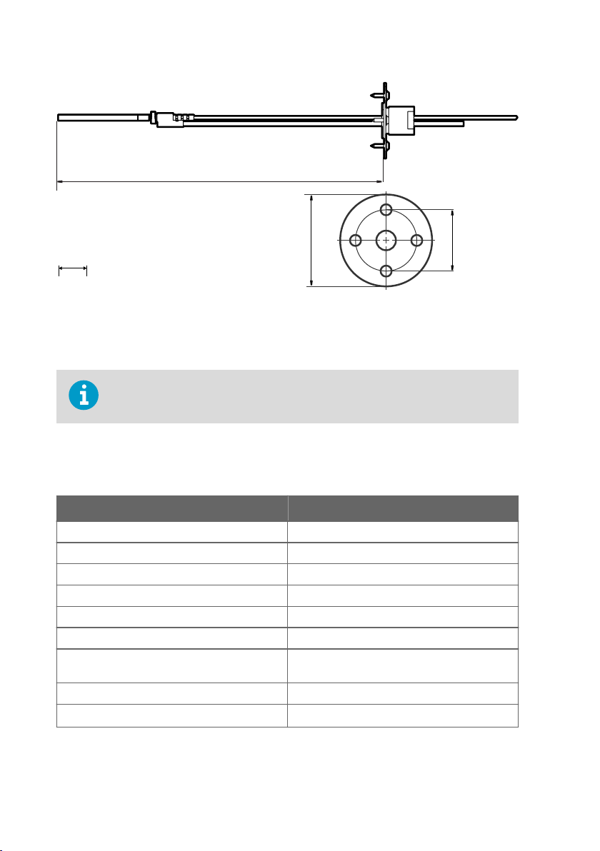
135 ... 370 [5.31 ... 14.56]
50 [1.96]
75 [2.95]
mm
[in]
HMP3, HMP4, HMP5, HMP7, HMP8, HMP9, MMP8, TMP1 User Guide M212022EN-D
Figure 45 Optional duct kit 215003 dimensions
8.9
Accessories and spare parts
Information on spare parts, accessories, and calibration products is available
online at www.vaisala.com and store.vaisala.com.
Connection cables
Table 38 Connection cables
Description Item code
Connection cable, M12-5F - M12-5M, 1 m INDIGOCABLE1M
Connection cable, M12-5F - M12-5M, 3 m INDIGOCABLE3M
Connection cable, M12-5F - M12-5M, 5 m INDIGOCABLE5M
Connection cable, M12-5F - M12-5M, 10 m INDIGOCABLE10M
Connection cable, M12-5F - open wires, 1.5 m 223263SP
Connection cable, M12-5F - open wires, 10 m 216546SP
Connection cable, M12-5F 90° - open wires,
0.6 m
Flat cable, M12-5F - M12-5M, 1 m CBL210493SP
USB PC connection cable
1) Vaisala Insight software for Windows available at www.vaisala.com/insight
72
1)
244669SP
242659
Page 75

HMP3
Table 39 Accessories
Description Order code
Duct installation kit 210697
Solar radiation shield DTR502B DTR502B
Table 40 Spare parts
Description Item code
Sensors
HUMICAPâ R2 VHM180
Filters
Sintered stainless steel filter HM47280SP
Stainless steel grid filter HM47453SP
Metallized PPS plastic grid filter DRW010276SP
Metallized PPS plastic grid with stainless steel
mesh filter
DRW010281SP
HMP4
Chapter 8 – Technical data
Table 41 Spare parts
Description Item code
Sintered stainless steel filter HM47280SP
Stainless steel grid HM47453SP
Metallized PPS plastic grid with stainless steel
mesh filter
Metallized PPS plastic grid filter DRW010276SP
DRW010281SP
HMP5
Table 42 Accessories
Description Item code
Mounting flange 210696
73
Page 76

HMP3, HMP4, HMP5, HMP7, HMP8, HMP9, MMP8, TMP1 User Guide M212022EN-D
Table 43 Spare parts
Description Item code
Sintered stainless steel filter HM47280SP
Stainless steel grid HM47453SP
Metallized PPS plastic grid with stainless steel
mesh filter
Metallized PPS plastic grid filter DRW010276SP
DRW010281SP
HMP7
Table 44 Accessories
Description Item code
Duct installation kit for RH probe 210697
Solar radiation shield DTR502B DTR502B
Cable gland M20×1.5 with split seal HMP247CG
Swagelokâ for 12 mm probe, 1/2" ISO thread SWG12ISO12
Swagelokâ for 12 mm probe, 3/8" ISO thread SWG12ISO38
Swagelokâ for 12 mm probe, 1/2" NPT thread SWG12NPT12
Table 45 Spare parts
Description Item code
Sintered stainless steel filter HM47280SP
Stainless steel grid HM47453SP
Metallized PPS plastic grid with stainless steel
mesh filter
Metallized PPS plastic grid filter DRW010276SP
DRW010281SP
HMP8
Table 46 Accessories
Description Item code
Ball valve 1/2" with ISO 1/2" welding joint BALLVALVE-1
74
Page 77

Table 47 Spare parts
Description Item code
Sintered stainless steel filter HM47280SP
Stainless steel grid HM47453SP
Metallized PPS plastic grid with stainless steel
mesh filter
Metallized PPS plastic grid filter DRW010276SP
DRW010281SP
HMP9
Table 48 Accessories
Description Item code(s)
Solar radiation shield DTR502B with sensor
head support 215130
DTR502B and 215130
MMP8
Table 49 Accessories
Description Item code
Ball valve ISO 1/2" with welding joint BALLVALVE-1
Ball valve ISO 1/2" with thread joint ISO 3/4" BALLVALVE-2
Chapter 8 – Technical data
Table 50 Spare parts
Description Item code
Stainless steel grid filter HM47453
Stainless steel grid filter for high flow rates (> 1
m/s)
220752
TMP1
Table 51 Accessories
Description Item code
Duct installation kit for T probe 215003
Swagelokâ for 6 mm probe 1/8" ISO thread SWG6ISO18
75
Page 78

HMP3, HMP4, HMP5, HMP7, HMP8, HMP9, MMP8, TMP1 User Guide M212022EN-D
Description Item code
Swagelokâ for 6 mm probe 1/8" NPT thread SWG6NPT18
76
Page 79

Appendix A – Modbus reference
Appendix A. Modbus reference
A.1 Default communication settings
Table 52 Default Modbus serial communication settings
Property Description/value
Serial bit rate 19200
Parity None
Number of data bits 8
Number of stop bits 2
Flow control None
Modbus device address 240
You can use up to ten probes on the same RS-485 line. You must configure each probe on the
line to have a dierent Modbus address.
A.2
Function codes
Table 53 Modbus function codes
Function code
(decimal)
03 03
16 10
43 / 14 2B
Function code
(hexadecimal)
hex
hex
/ 0E
hex
hex
Name Notes
Read Holding
Registers
Write Multiple
Registers
Read Device
Identification
Class 0
Class 0
A.3 Data encoding
In the data registers, the numeric values are available in one or two formats with separate
register addresses: 32-bit IEEE floating point format and/or 16-bit signed integer format.
77
Page 80

HMP3, HMP4, HMP5, HMP7, HMP8, HMP9, MMP8, TMP1 User Guide M212022EN-D
A.3.1 32-bit floating point or integer format
Least significant 16 bits of floating point or integer numbers are placed at the smaller Modbus
address as specified in Open Modbus TCP Specification, Release 1.0. This is also known as
"little-endian" or "Modicon" word order. Floating point values are represented in standard IEEE
32-bit floating point format.
Despite the specification, some Modbus masters may expect "big-endian" word
order (most significant word first). In such case, you must select "word-swapped"
floating point format in your Modbus master for the Modbus registers of the
device.
A "quiet NaN" value is returned for unavailable values. A quiet NaN is, for example,
7FC00000
; however, the master should understand any NaN value.
hex
A complete 32-bit floating point or integer value should be read and written in a
single Modbus transaction.
A.3.2 16-bit integer format
Some 16-bit integer values in the data registers are scaled to include the necessary decimals.
The scaling factors for those values are shown in the register tables.
Table 54 16-bit signed integer format details
Value Description
0000
8002
8000
hex
hex
hex
… 7FFE
… FFFF
hex
hex
Value in range 0 … 32766
Value in range -32766 … -1 (2’s complement)
Value is not available (quiet NaN)
Some values may exceed the signed 16-bit range even in normal operation. To
access such values, use the floating point registers instead.
A.4 Modbus registers
CAUTION!
addresses in actual Modbus messages (Modbus Protocol Data Unit (PDU) are in
hexadecimal and start from zero. Subtract 1 from the register number presented
in this manual to get the address used in the Modbus message (for example,
register number 1 corresponds to address 0
78
Registers are numbered in decimal, starting from one. Register
in the actual Modbus message).
hex
Page 81

Appendix A – Modbus reference
Accessing unavailable (temporarily missing) measurement data does not generate an
exception. “Unavailable” value (a quiet NaN for floating point data or 8000
for integer data)
hex
is returned instead. An exception is generated only for any access outside the applicable
register ranges.
A.4.1 Measurement Data Registers
Table 55 Floating point measurement data registers (read-only)
Register
number
Address
(hexadecimal)
(decimal)
1 0000
0001
3 0002
0003
7 0006
0007
9 0008
0009
11 000A
000B
13 000C
000D
15 000E
000F
17 0010
0011
19 0012
0013
21 0014
0015
23 0016
0017
hex
hex
hex
hex
hex
hex
hex
hex
hex
hex
hex
hex
hex
hex
hex
hex
hex
hex
hex
hex
hex
hex
Register description Data format Unit
Relative humidity 32-bit float %RH
Temperature 32-bit float °C
Dew point temperature 32-bit float °C
Dew/frost point
32-bit float °C
temperature
Dew/frost point
32-bit float °C
temperature at 1 atm
Dew point temperature
32-bit float °C
at 1 atm
Absolute humidity 32-bit float
g/m
Mixing ratio 32-bit float g/kg
Wet-bulb temperature 32-bit float °C
Water concentration 32-bit float ppm
Water vapor pressure 32-bit float hPa
3
v
79
Page 82

HMP3, HMP4, HMP5, HMP7, HMP8, HMP9, MMP8, TMP1 User Guide M212022EN-D
Register
number
Address
(hexadecimal)
(decimal)
25 0018
0019
27 001A
001B
29 001C
001D
31 001E
001F
33 0020
0021
35 0022
0023
41 0028
0029
65 0040
0041
hex
hex
hex
hex
hex
hex
hex
hex
hex
hex
hex
hex
hex
hex
hex
hex
Register description Data format Unit
Water vapor saturation
32-bit float hPa
pressure
Enthalpy 32-bit float kJ/kg
Water activity 32-bit float
Dew point temperature
32-bit float °C
dierence
Absolute humidity at
32-bit float
g/m
NTP
Water concentration in
32-bit float ppm
oil
Relative saturation 32-bit float %
Water mass fraction 32-bit float ppm
3
v
w
Table 56 Integer measurement data registers (read-only)
Register
number
Address
(hexadecimal)
Register description Data format Scale
(decimal)
257 0100
258 0101
260 0103
261 0104
262 0105
hex
hex
hex
hex
hex
Relative humidity 16-bit signed
Temperature 16-bit signed
Dew point
temperature
Dew/frost point
temperature
Dew/frost point
temperature at 1 atm
80
integer
integer
16-bit signed
integer
16-bit signed
integer
16-bit signed
integer
factor
OsetUnit
100 0 %RH
100 0 °C
100 0 °C
100 0 °C
100 0 °C
Page 83

Appendix A – Modbus reference
Register
number
(decimal)
Address
(hexadecimal)
263 0106
264 0107
265 0108
266 0109
267 010A
268 010B
269 010C
270 010D
271 010E
272 010F
273 0110
274 0111
277 0114
289 0120
hex
hex
hex
hex
hex
hex
hex
hex
hex
hex
hex
hex
hex
hex
Register description Data format Scale
Dew point
temperature at 1 atm
16-bit signed
integer
Absolute humidity 16-bit signed
factor
100 0 °C
100 0
integer
Mixing ratio 16-bit signed
100 0 g/kg
integer
Wet-bulb
temperature
Water concentration 16-bit signed
16-bit signed
integer
100 0 °C *
1 0 ppm
integer
Water vapor
pressure
Water vapor
saturation pressure
Enthalpy 16-bit signed
16-bit signed
integer
16-bit signed
integer
10 0 hPa
10 0 hPa
100 0 kJ/kg
integer
Water activity 16-bit signed
10000 0
integer
Dew point
temperature
16-bit signed
integer
10 0 °C
dierence
Absolute humidity at
NTP
Water concentration
in oil
Relative saturation 16-bit signed
16-bit signed
integer
16-bit signed
integer
100 0
1 0 ppm
100 0 % *
integer
Water vapor mass
fraction
16-bit signed
integer
1 0 ppm
OsetUnit
g/m
g/m
3
v
3
v
w
81
Page 84

HMP3, HMP4, HMP5, HMP7, HMP8, HMP9, MMP8, TMP1 User Guide M212022EN-D
A.4.2 Configuration registers
Table 57 Modbus configuration data registers (writable)
Register
number
(decimal)
General
1287 0506
1289 0508
2561 0A00
Compensation setpoints
769 0300
Register
address
(hexadecim
al)
hex
hex
hex
hex
0301
hex
Register description Data format Unit / valid range
Extra heat on/o. Enables
heating of humidity sensor
when close to saturation.
16-bit
boolean
0 = o (default)
1 = on
Measurement is disabled
for the duration of heating
and cooling.
Probe heating on/o.
Available on HMP7 model
only.
16-bit
boolean
0 = o (default)
1 = on
When on, output
parameters that depend
on temperature
measurement (for
example, relative
humidity) are disabled
unless temperature is
written to register 0334
hex
from an external source.
User information Text Text string of 24 bytes in
UTF-8 encoding
Pressure compensation
setpoint
32-bit float Unit: hPA
Default: 1013.25 hPa
82
Page 85

Compensation setpoints
821 0334
Purge
773 0304
1283 0502
1284 0503
Filtering
795 031A
0335
0305
031B
hex
hex
hex
hex
hex
hex
hex
hex
Appendix A – Modbus reference
Temperature
32-bit float Unit: °C
compensation setpoint. If
a value is written to this
register, probe uses it
instead of its own
temperature
measurement.
When probe heating is in
use, temperature must be
written to this register to
enable output parameters
that depend on
temperature measurement
(for example, relative
humidity).
Purge interval 32-bit float Unit: min
10 ... 14400
Interval purge on/o 16-bit
boolean
Startup purge on/o 16-bit
boolean
Measurement filtering
32-bit float Range: 0.000 ... 1.000
factor
0 = O
1 = On
0 = O
1 = On
1.000 = Reading shows
100% of the most recent
measured value (no
filtering, default)
0.01 ... 0.99 = Reading
shows 1 ... 99% of the most
recent measured value and
part of the previous
reading (filtering is
applied). For example,
"0.9" means that the
filtered measurement
reading = 90% of the most
recent measured value +
10% of the previous
reading.
83
Page 86

HMP3, HMP4, HMP5, HMP7, HMP8, HMP9, MMP8, TMP1 User Guide M212022EN-D
Filtering
1282 0501
hex
Enable of disable
measurement filtering
using the user-defined
16-bit
boolean
0 = O
1 = On
filtering factor (register
031A
)
hex
Communication
1537 0600
1538 0601
hex
Modbus address 16-bit
hex
integer
Bit rate enum 0 = 300
1 ... 247
Default: 240
1 = 600
2 = 1200
3 = 2400
4 = 4800
5 = 9600
6 = 19200
7 = 38400
8 = 57600
9 = 115200
1539 0602
Parity, data, stop bits enum 0 = None, 8, 1
hex
1 = None, 8, 2
2 = Even, 8, 1
3 = Even, 8, 2
4 = Odd, 8, 1
5 = Odd, 8, 2
(default: 1 = None, 8, 2)
1540 0603
Functions
1285 0504
1542 0605
Response delay 16-bit
hex
Start purge 16-bit
hex
Restart device 16-bit
hex
integer
function
status
function
status
Unit: ms
Range: 0 ... 1000
When writing to register:
1 = Start purge
When writing to register:
1 = Restart the device
84
Page 87

A.4.3 Device identification objects
Table 58 Device identification objects
Appendix A – Modbus reference
Object id
(decimal)
0 00
1 01
2 02
3 03
4 04
5 05
6 06
128 80
129 81
130 82
Object id
(hexadecimal)
hex
hex
hex
hex
hex
hex
hex
hex
hex
hex
Object name Example contents
VendorName “Vaisala”
ProductCode "HMP4"
MajorMinorVersion "1.2.3"
VendorUrl “http://www.vaisala.com/”
ProductName "Humidity and Temperature Probe
ModelName "7E2A2A0A000"
UserApplicationName User definable information text (see
SerialNumber
CalibrationDate
CalibrationText
1) Vaisala-specific device identification object.
Software version of the device.
HMP4"
Configuration code of the device.
Length and content of the code are
model-specific.
configuration register 0A00
1)
1)
“K0710040”
"2020-01-31"
hex
)
Calibration date in YYYY-MM-DD
format. Empty string if not set/valid.
1)
Calibration information text. Empty
string if not set/valid.
A.4.4 Status registers
Table 59 Modbus status data registers (read-only)
Register
number
(decimal
)
513 0200
Address
(hexade
cimal)
hex
Register description Data format Note
Error status 16-bit boolean 0000
active
0001
hex
: No errors
hex
: One or more errors
85
Page 88

HMP3, HMP4, HMP5, HMP7, HMP8, HMP9, MMP8, TMP1 User Guide M212022EN-D
Register
number
(decimal
Address
(hexade
cimal)
)
514 0201
516 0203
0204
518 0205
0206
520 0207
521 0208
522 0209
523 020A
Register description Data format Note
Online status 16-bit boolean 0000
hex
Error code 32-bit signed
hex
hex
Security hash 32-bit signed
hex
hex
RH measurement
hex
status
T measurement
hex
status
Tdf measurement
hex
status
Device status 16-bit signed integer 0000
hex
integer
integer
16-bit signed integer 0000
16-bit signed integer
16-bit signed integer
: Output locked
hex
0001
: Online data available
hex
See Table 60 (page 86).
Security hash changes when
any change is made to device
settings or adjustments.
: Status OK
hex
0002
: Reading is not reliable
hex
0004
: Under range
hex
0008
: Over range
hex
0020
: Value locked
hex
0080
: Sensor failure
hex
0100
: Measurement not
hex
ready
: Status OK
hex
0001
: Critical error,
hex
maintenance needed
0002
: Error, device may
hex
recover automatically
0004
: Warning
hex
0008
: Notification
hex
0010
: Calibration mode
hex
active
Table 60 Error codes in register 0203
hex
Bitmask Error message Severity
0000
0001
0002
0004
hex
hex
hex
hex
Status OK
Temperature measurement error Error
Humidity measurement error Error
Humidity sensor failure Error
86
Page 89

Appendix A – Modbus reference
Bitmask Error message Severity
0008
hex
0010
hex
800000
Capacitance reference error Error
Ambient temperature out of range Error
Sensor heater failure Warning
hex
A.4.5 Test value registers
Read the known test values from the test registers to verify the functionality of your Modbus
implementation.
Table 61 Modbus test registers (read-only)
Register number
(decimal)
Register address
(hexadecimal)
7937 1F00
7938 1F01
1F02
7940 1F03
1F04
1F05
1F06
hex
hex
hex
hex
hex
hex
hex
Register
description
Signed integer
Data format Test value
16-bit integer -12345
test
Floating point
32-bit float -123.45
test
Text string test text Text string
"-123.45"
87
Page 90

HMP3, HMP4, HMP5, HMP7, HMP8, HMP9, MMP8, TMP1 User Guide M212022EN-D
A.4.6 Modbus communication examples
Reading relative humidity value
Device address used in the following examples is 240 (F0
hex
).
The values returned by the device dier depending on the ambient conditions
and/or device settings. Your device might not return exactly same values.
Request Response
Bytes on the line
(hexadecimal)
(silence for 3.5 bytes) Start of Modbus RTU
F0
hex
03
hex
00
hex
00
hex
00
hex
02
hex
D1
hex
2A
hex
(silence for 3.5 bytes) End of Modbus RTU
Description Bytes on the line
(hexadecimal)
(silence for 3.5 bytes) Start of Modbus RTU
frame
Probe address F0
Function (Read
Holding Registers)
Register address 04
Number of 16-bit
registers to read (2)
Modbus RTU
checksum
frame
03
7A
E1
41
F4
05
06
hex
hex
hex
hex
hex
hex
hex
hex
hex
Description
frame
Probe address
Function (Read
Holding Registers)
Number of data bytes
Value of first register
(least significant
word)
Value of second
register (most
significant word)
Modbus RTU
checksum
(silence for 3.5 bytes) End of Modbus RTU
frame
Communication description
Register address 1 (1-based Modbus documentation format) =
0000
(0-based format used in actual
hex
communication).
Data format Two 16-bit Modbus registers interpreted as IEEE
754 binary32 floating point value, least
significant word first.
Returned value 41F47AE1
, which is binary32 representation of
hex
30.56 (%RH).
88
Page 91

Writing pressure compensation value
Request Response
Bytes on the line
(hexadecimal)
(silence for 3.5 bytes) Start of Modbus RTU
Description Bytes on the line
(hexadecimal)
(silence for 3.5 bytes) Start of Modbus RTU
frame
F0
10
03
00
00
02
04
6E
14
44
75
AB
4E
hex
hex
hex
hex
hex
hex
hex
hex
hex
hex
hex
hex
hex
Probe address F0
Function (Write
10
Multiple Registers)
Register address 03
00
Number of registers to
write (2)
00
02
Number of data bytes AD
Value for first register
54
(least significant
word)
Value for second
(silence for 3.5 bytes) End of Modbus RTU
register (least
significant word)
Modbus RTU
checksum
hex
hex
hex
hex
hex
hex
hex
hex
(silence for 3.5 bytes) End of Modbus RTU
frame
Appendix A – Modbus reference
Description
frame
Probe address
Function (Write
Multiple Registers)
Register address
Number of 16-bit
registers written (2)
Modbus RTU
checksum
frame
The response to a write
function informs that the
function was correctly received
by the device. It does not
guarantee that the written
value was accepted by the
device (for example, in case
out-of-range values).
To verify that the value was
really accepted by the device,
read the register value after
writing.
Communication description
Register address 769 (1-based Modbus documentation format) =
0300
(0-based format used in actual
hex
communication).
89
Page 92

HMP3, HMP4, HMP5, HMP7, HMP8, HMP9, MMP8, TMP1 User Guide M212022EN-D
Communication description
Data format Two 16-bit Modbus registers interpreted as IEEE
754 binary32 floating point value, least
significant word first.
Value to write 44756E14
= 981.72 (hPa)
hex
90
Page 93

Online store
Accessories, spare parts, and calibration and repair products are available online at
store.vaisala.com.
Warranty
For standard warranty terms and conditions, see www.vaisala.com/warranty.
Please observe that any such warranty may not be valid in case of damage due to normal wear
and tear, exceptional operating conditions, negligent handling or installation, or unauthorized
modifications. Please see the applicable supply contract or Conditions of Sale for details of the
warranty for each product.
Technical support
Contact Vaisala technical support at helpdesk@vaisala.com. Provide at least the
following supporting information as applicable:
• Product name, model, and serial number
• Software/Firmware version
• Name and location of the installation site
• Name and contact information of a technical person who can provide further
information on the problem
For more information, see www.vaisala.com/support.
Recycling
Recycle all applicable material.
Follow the statutory regulations for disposing of the product and packaging.
91
Page 94

Page 95

Page 96

www.vaisala.com
 Loading...