

Page 1
USER'S GUIDE
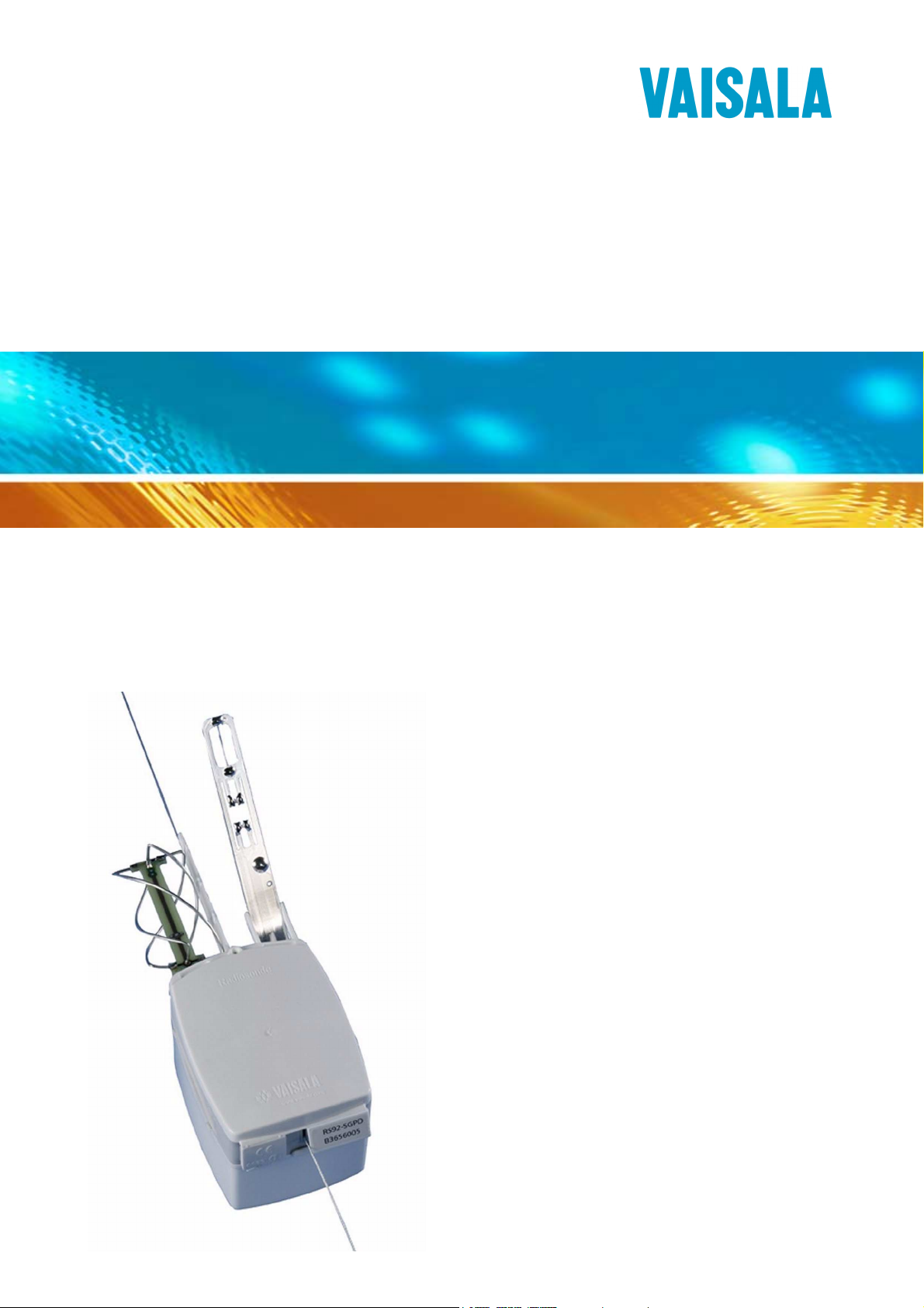
Vaisala Radiosonde
RS92-SGP
M210295EN-G
Page 2

PUBLISHED BY
Vaisala Oyj Phone (int.): +358 9 8949 1
P.O. Box 26 Fax: +358 9 8949 2227
FIN-00421 Helsinki
Finland
Visit our Internet pages at http://www.vaisala.com/
© Vaisala 2010
No part of this manual may be reproduced in any form or by any means,
electronic or mechanical (including photocopying), nor may its contents
be communicated to a third party without prior written permission of the
copyright holder.
The contents are subject to change without prior notice.
Please observe that this manual does not create any legally binding
obligations for Vaisala towards the customer or end user. All legally
binding commitments and agreements are included exclusively in the
applicable supply contract or Conditions of Sale.
Page 3

________________________________________________________________________________
Table of Contents
CHAPTER 1
GENERAL INFORMATION . . . . . . . . . . . . . . . . . . . . . . . . . . . . . . . . . . . . . .7
About This Manual . . . . . . . . . . . . . . . . . . . . . . . . . . . . . . . . .7
Contents of This Manual . . . . . . . . . . . . . . . . . . . . . . . . . . . 7
Version Information . . . . . . . . . . . . . . . . . . . . . . . . . . . . . . .8
Related Manuals . . . . . . . . . . . . . . . . . . . . . . . . . . . . . . . . . 8
General Safety Considerations . . . . . . . . . . . . . . . . . . . . . . 8
Feedback . . . . . . . . . . . . . . . . . . . . . . . . . . . . . . . . . . . . . . . 9
Product-Related Safety Precautions . . . . . . . . . . . . . . . . . . . 9
Recycling . . . . . . . . . . . . . . . . . . . . . . . . . . . . . . . . . . . . . . . . 10
License Agreement . . . . . . . . . . . . . . . . . . . . . . . . . . . . . . . . 10
CHAPTER 2
PRODUCT OVERVIEW . . . . . . . . . . . . . . . . . . . . . . . . . . . . . . . . . . . . . . . 11
Introduction to Vaisala RS92-SGP . . . . . . . . . . . . . . . . . . . . 11
CHAPTER 3
OPERATION . . . . . . . . . . . . . . . . . . . . . . . . . . . . . . . . . . . . . . . . . . . . . . . .13
General . . . . . . . . . . . . . . . . . . . . . . . . . . . . . . . . . . . . . . . . . .13
Preparing the Balloon and Optional Sounding
Accessories . . . . . . . . . . . . . . . . . . . . . . . . . . . . . . . . . . . . . . 14
Balloon Preparation . . . . . . . . . . . . . . . . . . . . . . . . . . . . . .14
Optional Sounding Accessories . . . . . . . . . . . . . . . . . . . . . 18
Totex Parachute 5710-5 . . . . . . . . . . . . . . . . . . . . . . . 18
Radar Reflector . . . . . . . . . . . . . . . . . . . . . . . . . . . . . . 19
Non-Totex Parachute. . . . . . . . . . . . . . . . . . . . . . . . . . 19
Unpacking the Radiosonde . . . . . . . . . . . . . . . . . . . . . . . . .21
Preparing the Sounding . . . . . . . . . . . . . . . . . . . . . . . . . . . .23
Connecting the Battery Set . . . . . . . . . . . . . . . . . . . . . . . . . 26
General . . . . . . . . . . . . . . . . . . . . . . . . . . . . . . . . . . . . . . . 26
Connecting the Battery . . . . . . . . . . . . . . . . . . . . . . . . . . .27
Connecting the Dry-cell Battery Set with Switch . . . . . . . . 29
Checking the Connection. . . . . . . . . . . . . . . . . . . . . . . 33
Connecting the Water-activated Battery . . . . . . . . . . . . . . 34
Removing the Battery Case . . . . . . . . . . . . . . . . . . . . . . . . 37
Launching the Radiosonde . . . . . . . . . . . . . . . . . . . . . . . . . 37
Attaching the Unwinder . . . . . . . . . . . . . . . . . . . . . . . . . . .37
Attaching the Unwinder to the Balloon. . . . . . . . . . . . . 38
Totex Parachute . . . . . . . . . . . . . . . . . . . . . . . . . . . . . 38
Radar Reflector . . . . . . . . . . . . . . . . . . . . . . . . . . . . . . 39
Non-Totex Parachute. . . . . . . . . . . . . . . . . . . . . . . . . . 39
VAISALA________________________________________________________________________ 1
Page 4

User's Guide ______________________________________________________________________
Releasing the Balloon . . . . . . . . . . . . . . . . . . . . . . . . . . . .39
Checking the Reception . . . . . . . . . . . . . . . . . . . . . . . . . . .39
Monitoring the Sounding with the Sounding System . . . .40
CHAPTER 4
STORAGE AND TRANSPORTATION . . . . . . . . . . . . . . . . . . . . . . . . . . . .41
Storage . . . . . . . . . . . . . . . . . . . . . . . . . . . . . . . . . . . . . . . . . .41
Transportation . . . . . . . . . . . . . . . . . . . . . . . . . . . . . . . . . . . .42
Transporting Lithium Batteries and RS92 Radiosondes . .42
CHAPTER 5
FAILURE REPORT AND WARRANTY . . . . . . . . . . . . . . . . . . . . . . . . . . .45
Failure Report . . . . . . . . . . . . . . . . . . . . . . . . . . . . . . . . . . . .45
Technical Support . . . . . . . . . . . . . . . . . . . . . . . . . . . . . . . . .46
Radiosonde Warranty . . . . . . . . . . . . . . . . . . . . . . . . . . . . . .46
Vaisala Radiosonde Warranty Statement . . . . . . . . . . . . .46
Storage Conditions . . . . . . . . . . . . . . . . . . . . . . . . . . . 47
Transportation and Handling . . . . . . . . . . . . . . . . . . . . 47
Criteria for Radiosonde Failures . . . . . . . . . . . . . . . . . 47
Making Warranty Claims . . . . . . . . . . . . . . . . . . . . . . . 48
APPENDIX A
SAFETY INSTRUCTIONS FOR BALLOON OPERATORS . . . . . . . . . . . .49
2 ___________________________________________________________________ M210295EN-G
Page 5

________________________________________________________________________________
List of Figures
Figure 1 Vaisala Radiosonde RS92-SGP . . . . . . . . . . . . . . . . . . . . . . . 12
Figure 2 Loading Weights onto the Gas Nozzle. . . . . . . . . . . . . . . . . . . 14
Figure 3 Attaching the Balloon to the Gas Nozzle . . . . . . . . . . . . . . . . . 15
Figure 4 Inflating the Balloon . . . . . . . . . . . . . . . . . . . . . . . . . . . . . . . . . 15
Figure 5 Balloon Raises the Gas Nozzle . . . . . . . . . . . . . . . . . . . . . . . .16
Figure 6 Securing the Neck of the Balloon. . . . . . . . . . . . . . . . . . . . . . . 16
Figure 7 Removing the Balloon from the Gas Nozzle . . . . . . . . . . . . . .17
Figure 8 Folding the Neck of the Balloon . . . . . . . . . . . . . . . . . . . . . . . .17
Figure 9 Vaisala Radiosonde Sounding Accessories. . . . . . . . . . . . . . .20
Figure 10 Opening the Foil Bag . . . . . . . . . . . . . . . . . . . . . . . . . . . . . . . . 21
Figure 11 Contents of the Radiosonde Package . . . . . . . . . . . . . . . . . . .22
Figure 12 Unwinder Details . . . . . . . . . . . . . . . . . . . . . . . . . . . . . . . . . . . 22
Figure 13 Vaisala Ground Check Set GC25 . . . . . . . . . . . . . . . . . . . . . . 23
Figure 14 Radiosonde in the GC25 with the Communication Cable
Connected . . . . . . . . . . . . . . . . . . . . . . . . . . . . . . . . . . . . . . . .24
Figure 15 Placing the Sensor Boom into Flight Position . . . . . . . . . . . . . 25
Figure 16 RSB511 Dry-cell Battery Set (Number 1) and RSB611
Lithium Battery (Number 2) . . . . . . . . . . . . . . . . . . . . . . . . . . .26
Figure 17 RSB912P Water-activated Battery. . . . . . . . . . . . . . . . . . . . . .27
Figure 18 Battery Package. . . . . . . . . . . . . . . . . . . . . . . . . . . . . . . . . . . .27
Figure 19 Battery Connector Shown with RSB611 . . . . . . . . . . . . . . . . . 28
Figure 20 Connecting the Battery Connector to the Radiosonde. . . . . . .28
Figure 21 Battery Package for Dry-cell Battery Set with Switch. . . . . . . .29
Figure 22 Battery Connector . . . . . . . . . . . . . . . . . . . . . . . . . . . . . . . . . .30
Figure 23 Placing Battery Connector into Connector Holder, Part 1 . . . . 30
Figure 24 Placing Battery Connector into Connector Holder, Part 2 . . . . 31
Figure 25 Connecting the Radiosonde to the Battery Case. . . . . . . . . . . 32
Figure 26 Pressing Battery Case and Radiosonde Together. . . . . . . . . . 32
Figure 27 Green LED Light is Lit . . . . . . . . . . . . . . . . . . . . . . . . . . . . . . . 33
Figure 28 Battery Package for Water-Activated Battery. . . . . . . . . . . . . .34
Figure 29 Battery Immersed in Water . . . . . . . . . . . . . . . . . . . . . . . . . . .35
Figure 30 Battery in the Case, Waxed End Circled . . . . . . . . . . . . . . . . . 35
Figure 31 Connecting the Battery Connector to the Radiosonde. . . . . . .36
Figure 32 Removing the Battery Case . . . . . . . . . . . . . . . . . . . . . . . . . . .37
Figure 33 Attaching the Unwinder to the Balloon. . . . . . . . . . . . . . . . . . .38
Figure 34 Lithium Battery Handling Label . . . . . . . . . . . . . . . . . . . . . . . .43
VAISALA________________________________________________________________________ 3
Page 6

User's Guide ______________________________________________________________________
4 ___________________________________________________________________ M210295EN-G
Page 7

________________________________________________________________________________
List of Tables
Table 1 Manual Versions . . . . . . . . . . . . . . . . . . . . . . . . . . . . . . . . . . . . .8
Table 2 Related Manuals . . . . . . . . . . . . . . . . . . . . . . . . . . . . . . . . . . . . . 8
Table 3 Ordering Codes for Optional Sounding Accessories . . . . . . . . . .18
Table 4 RS92-SGP Battery Sets. . . . . . . . . . . . . . . . . . . . . . . . . . . . . . . .26
VAISALA________________________________________________________________________ 5
Page 8

User's Guide ______________________________________________________________________
6 ___________________________________________________________________ M210295EN-G
Page 9

Chapter 1 ________________________________________________________ General Information
CHAPTER 1
GENERAL INFORMATION
This chapter provides general notes for the manual and the product.
About This Manual
This manual provides information for operating the Vaisala Radiosonde
RS92-SGP.
Contents of This Manual
This manual consists of the following chapters:
- Chapter 1, General Information: This chapter provides general
notes for the manual and the product.
- Chapter 2, Product Overview: This chapter introduces the features
and advantages of the radiosonde.
- Chapter 3, Operation: This chapter contains information that is
needed to operate this product.
- Chapter 4, Storage and Transportation: This chapter provides
information for the transport and storage of the product.
- Chapter 5, Failure Report and Warranty: This chapter presents
information about the failure report and radiosonde warranty.
- Appendix A, Safety Instructions for Balloon Operators: This
appendix contains details of safe and proper balloon preparation.
VAISALA________________________________________________________________________ 7
Page 10
User's Guide ______________________________________________________________________
Version Information
Table 1 Manual Versions
Manual Code Description
M210295EN-G May 2010. This manual.Contains RS92-SGPL.
M210295EN-F October 2009. Previous version.
M210295EN-E Previous version
Related Manuals
Table 2 Related Manuals
Manual Code Manual Name
M210507EN AUTOSONDE AS14 User’s Guide
M210329EN Ground Check Set GC25 User's Guide
M210488EN Vaisala DigiCORA® User's Guide
M210547EN Digital Ozonesonde RS92 User's Guide
M210616EN Radioactivity Sounding with Digital Vaisala
Radiosonde RS92 User's Guide
M010024EN DigiCORA II MW15 User's Guide
M210811EN Configuring and Operating MW11/15 Systems,
RS92 Radiosonde, and GC25 Using Cable
Connection
WARNING
CAUTION
NOTE
General Safety Considerations
Throughout the manual, important safety considerations are highlighted
as follows:
Warning alerts you to a serious hazard. If you do not read and follow
instructions very carefully at this point, there is a risk of injury or even
death.
Caution warns you of a potential hazard. If you do not read and follow
instructions carefully at this point, the product could be damaged or
important data could be lost.
Note highlights important information on using the product.
8 ___________________________________________________________________ M210295EN-G
Page 11
Chapter 1 ________________________________________________________ General Information
Feedback
Vaisala Customer Documentation Team welcomes your comments and
suggestions on the quality and usefulness of this publication. If you find
errors or have other suggestions for improvement, please indicate the
chapter, section, and page number. You can send comments to us by email: manuals@vaisala.com.
Product-Related Safety Precautions
WARNING
WARNING
WARNING
CAUTION
CAUTION
Conduct soundings in a safe environment and in accordance with all
applicable restrictions and regulations.
Do not use the radiosonde in an area with power lines or other
obstructions overhead. Make sure that you check the area for such
obstructions before using the radiosonde.
Do not use the radiosonde without consultation and cooperation with
local and other applicable aviation authorities.
Do not modify the unit. Improper modification can damage the
product or lead to malfunction.
Do not use the radiosonde for any purpose other than for soundings.
VAISALA________________________________________________________________________ 9
Page 12
User's Guide ______________________________________________________________________
Recycle all applicable material.
Dispose of batteries and the unit according to statutory regulations.
Do not dispose of with regular household refuse.
Recycling
License Agreement
All rights to any software are held by Vaisala or third parties. The
customer is allowed to use the software only to the extent that is
provided by the applicable supply contract or Software License
Agreement.
10 __________________________________________________________________ M210295EN-G
Page 13

Chapter 2 __________________________________________________________ Product Overview
CHAPTER 2
PRODUCT OVERVIEW
This chapter introduces the features and advantages of the radiosonde.
Introduction to Vaisala RS92-SGP
The digital Vaisala Radiosonde RS92-SGP offers excellent data
availability, accuracy of humidity, pressure, temperature, and wind
measurement.
This radiosonde type features a GPS receiver for wind finding. The
RS92-SGP has a silicon pressure sensor, heated twin humidity sensor
and a small, fast temperature sensor. The RS92-SGP features easy
additional sensor capability. The synthesizer-based transmitter is stable
and uses a narrow bandwidth. The RS92-SGP is compliant with the
European ETSI standard for digital radiosondes operating in the 400
MHz band, EN 302 054.
In addition to regular soundings, the RS92-SGP radiosondes can be
used to conduct ozone and radioactivity soundings. When conducting
an ozone sounding, an ozone sensor with an interface unit is connected
to the radiosonde. When conducting a radioactivity sounding, an
integrated interface and radioactivity sensor unit is connected to the
radiosonde. Follow the procedures and guidelines in the relevant User’s
Guides to conduct additional sensor soundings.
VAISALA_______________________________________________________________________ 11
Page 14
User's Guide ______________________________________________________________________
0705-015
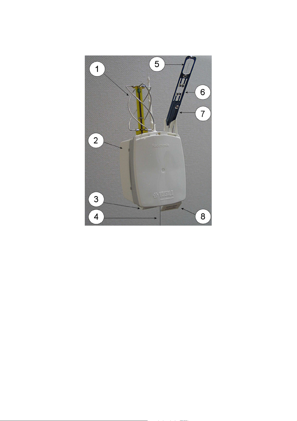
Figure 1 Vaisala Radiosonde RS92-SGP
1 = GPS antenna
2 = Battery case
3 = Additional sensor interface connector
4 = Antenna
5 = Temperature sensor
6 = Humidity sensors
7 = Sensor boom
8 = GC25 interface
The Vaisala Radiosonde RS92-SGP can be used with the Vaisala
Sounding Systems MW32, MW31 and MW21, and the Vaisala
Sounding Systems MW11, MW12, or MW15.
12 __________________________________________________________________ M210295EN-G
Page 15

Chapter 3 ________________________________________________________________ Operation
CHAPTER 3
OPERATION
This chapter contains information that is needed to operate this product.
General
It is essential that you carry out the pre-launch steps as instructed and
always in the same way. Follow the instructions in the sections below
and refer to Appendix A on page 49 for proper and safe balloon
preparation.
The workorder for a sounding is as follows:
1. Prepare the balloon and optional sounding accessories.
2. Unpack the radiosonde.
3. Prepare the sounding.
4. Connect the battery.
5. Launch the radiosonde.
6. Monitor the sounding with the sounding system.
When conducting additional sensor soundings (ozone or radioactivity
soundings), follow the procedures and guidelines in the relevant User’s
Guides.
VAISALA_______________________________________________________________________ 13
Page 16
User's Guide ______________________________________________________________________
Preparing the Balloon and Optional Sounding Accessories
The balloon and the optional sounding accessories must be prepared
before connecting the radiosonde battery and thereby activating the
radiosonde. This is necessary because the radiosonde should be
launched within 15 minutes of battery connection.
WARNING
WARNING
Read the safety instructions in Appendix A before proceeding.
Normally the balloon-lifting gas (hydrogen or helium) is supplied in
gas bottles, but hydrogen can also be produced with a hydrogen
generator. Carefully study the operation and safety instructions for the
gas bottle facilities or the hydrogen generator.
Take extreme caution when handling the inflated balloon.
Balloon Preparation
It is recommended that the balloon be prepared in a balloon filling
shed. The balloon filling shed must be well ventilated so that possible
gas leaks do not remain inside the shed, even in situations when there
is no electricity.
Follow these steps to prepare the balloon:
1. Load weights that are needed to obtain the required lift onto the gas
nozzle.
0705-020
Figure 2 Loading Weights onto the Gas Nozzle
14 __________________________________________________________________ M210295EN-G
Page 17
Chapter 3 ________________________________________________________________ Operation
2. Attach the balloon to the gas nozzle by securing the balloon with a
piece of string or a clamp.
0705-017
Figure 3 Attaching the Balloon to the Gas Nozzle
3. Inflate the balloon following the balloon manufacturer’s inflation
instructions. Do not leave the balloon-filling shed while inflating
the balloon.
0705-018
Figure 4 Inflating the Balloon
VAISALA_______________________________________________________________________ 15
Page 18

User's Guide ______________________________________________________________________
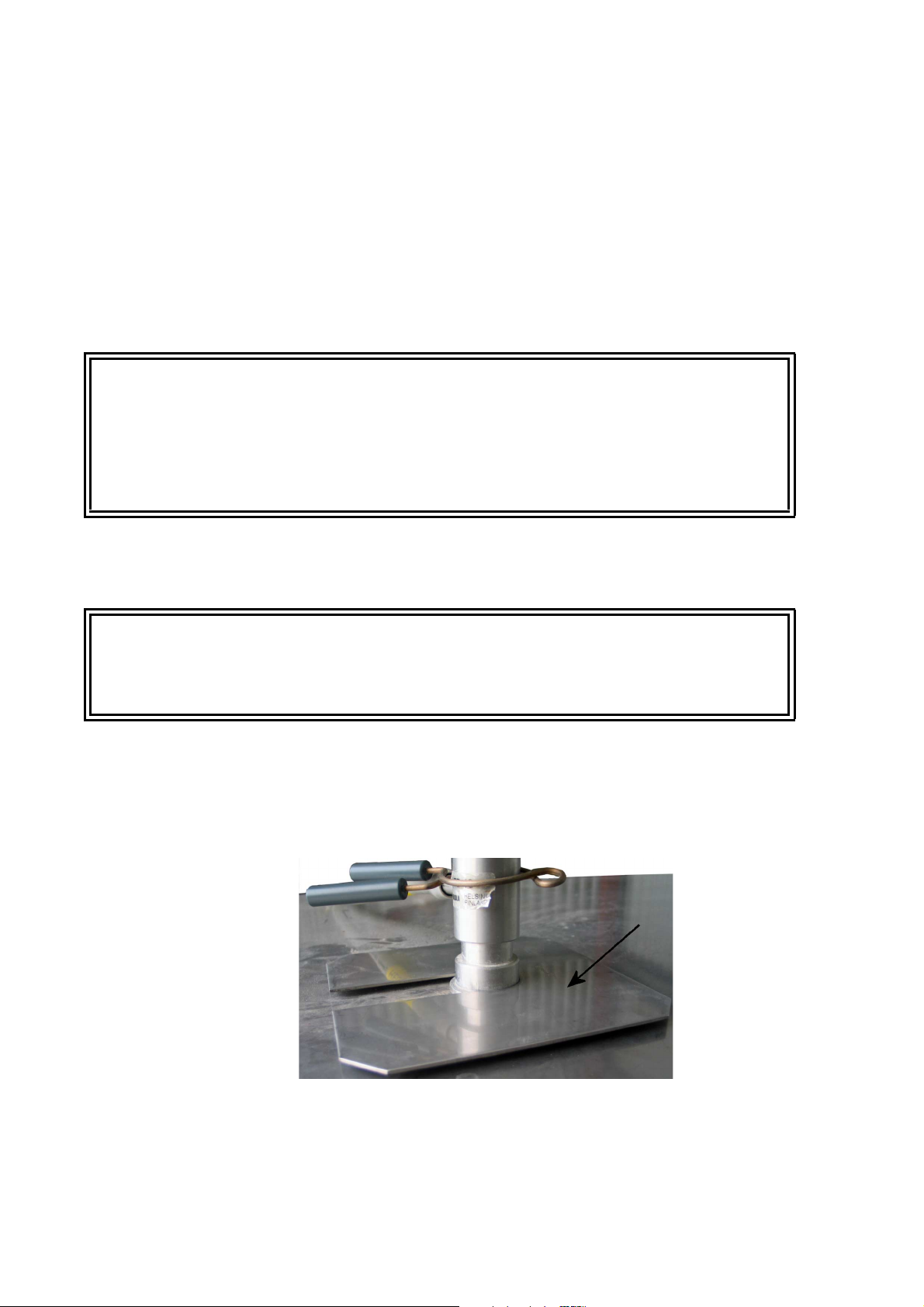
4. When the balloon is sufficiently filled, in other words, the balloon
just raises the gas nozzle, close the gas valve.
0705-019
Figure 5 Balloon Raises the Gas Nozzle
5. Secure the neck of the balloon tightly with a string before removing
the balloon from the gas nozzle.
0706-105
Figure 6 Securing the Neck of the Balloon
16 __________________________________________________________________ M210295EN-G
Page 19

Chapter 3 ________________________________________________________________ Operation
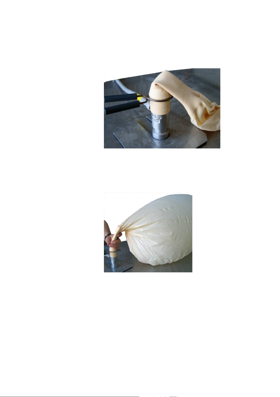
0705-021
Figure 7 Removing the Balloon from the Gas Nozzle
6. Fold the neck of the balloon over and secure it firmly. Tie the string
high enough to ensure that the unwinder fits easily.
0705-022
Figure 8 Folding the Neck of the Balloon
7. Leave the balloon waiting in the balloon-filling shed while you
prepare the radiosonde. Make sure the balloon does not touch
anything. Hold the balloon by the neck.
VAISALA_______________________________________________________________________ 17
Page 20

User's Guide ______________________________________________________________________
NOTE
When using a balloon with an integrated parachute, make sure that a
sufficiently long piece of the parachute string is poking out of the
balloon neck in order to fasten the string to the radiosonde unwinder.
Optional Sounding Accessories
The RS92 unwinder RSU911 is designed to be attached directly to the
folded balloon neck. However, you can use the same unwinder if you
use optional sounding accessories, such as a parachute or a radar
reflector.
Always attach the unwinder to a relatively firm support, such as the
balloon or the parachute spreader. The support must not let the
unwinder twist freely, or otherwise the suspension string might unwind
at too high a speed and the radiosonde hit the ground during the launch.
The unwinder must also be able to swing slightly during the sounding.
Attach all optional sounding accessories next to the balloon, or
otherwise they disturb the measuring environment of the radiosonde
and no proper temperature and humidity measurements can be made.
CAUTION
The strength of all the strings used during soundings must exceed 25
kp (250 N). Knots in the strings weaken the strength to the minimum
of 40 % of the original string strength. This results in a string strength
of 10 kp (100 N), which is sufficient for RS92 soundings.
Table 3 Ordering Codes for Optional Sounding Accessories
Item Code Note
Totex parachute 15046
Rubber plate RS46158 Used with a radar reflector
Hanger board RS46157 Used with a non-Totex parachute
Totex Parachute 5710-5
The recommended parachute is the Totex type 5710-5 (Vaisala code
15046). In the Totex parachute, an elastic ribbon loop hangs the
unwinder securely under the spreader.
Attach the parachute directly to the balloon with the parachute string.
18 __________________________________________________________________ M210295EN-G
Page 21

Chapter 3 ________________________________________________________________ Operation
Radar Reflector
Attach the unwinder to the radar reflector with a rubber plate accessory
(Vaisala code RS46158). The rubber plate accessory lets the unwinder
swing properly, making sure that the suspension string is unwound
smoothly.
1. Tie the radar reflector to the balloon with a string of approximately
50 cm in length.
2. Attach the rubber plate (RS46158) to the radar reflector.
See Figure 9 on page 20 for details. For unwinder attaching instructions,
see section Radar Reflector on page 39.
Non-Totex Parachute
If you are using a parachute that has no firm objects to prevent the
unwinder from twisting, you have to use a hanger board (Vaisala code
RS46157).
1. Tie the parachute to the balloon with a string.
2. Tie the hanger board to the parachute with a string of
approximately 20 cm in length.
See Figure 9 on page 20 for details. For unwinder attaching instructions,
see section Non-Totex Parachute on page 39.
VAISALA_______________________________________________________________________ 19
Page 22

User's Guide ______________________________________________________________________
0908-009
Figure 9 Vaisala Radiosonde Sounding Accessories
Option 1 = Sounding with a Totex parachute
Option 2 = Sounding with no sounding accessories
Option 3 = Sounding with a radar reflector
Option 4 = Sounding with a non-Totex Parachute
Now you can proceed to unpack the radiosonde.
20 __________________________________________________________________ M210295EN-G
Page 23

Chapter 3 ________________________________________________________________ Operation
Unpacking the Radiosonde
Follow these steps to unpack the radiosonde:
CAUTION
Do not touch or hit the sensors on the sensor boom. Be careful not to
bend the GPS antenna. By carefully handling the radiosonde and the
sensor boom as well as the GPS antenna, you ensure that the
radiosonde functions properly during the sounding.
1. Open the foil bag as indicated on the bag.
0912-232
Figure 10 Opening the Foil Bag
VAISALA_______________________________________________________________________ 21
Page 24

User's Guide ______________________________________________________________________
2. Lift the cardboard flap protecting the sensor boom. Be careful to
avoid touching or hitting the sensors on the sensor boom.
0705-024
Figure 11 Contents of the Radiosonde Package
1 = Radiosonde
2 = Unwinder
3=Battery
3. Remove the radiosonde from the package, free the antenna, and
take the unwinder out of the package.
4. Remove the small plastic rubber wire from the unwinder.
0601-048
Figure 12 Unwinder Details
1 = Rubber wire
2 = Unwinder lip
22 __________________________________________________________________ M210295EN-G
Page 25

Chapter 3 ________________________________________________________________ Operation
5. Make sure the plastic lip under which the string runs is level with
the unwinder bottom plate. If the lip is bent, bend it gently back to
level the position.
Proceed to prepare the sounding.
Preparing the Sounding
When preparing the sounding, the Vaisala Ground Check Set GC25 is
connected to the sounding system via cable and operated with the help
of the sounding software.
NOTE
If you are using DigiCORA® Sounding System MW21, software
version < 3.12, or MW15, MW12 or MW11, software version < 8.311,
refer to the Ground Check Set GC25 User’s Guide for information on
using the GC25 in the stand-alone mode.
0705-025
Figure 13 Vaisala Ground Check Set GC25
1 = Chamber
2=Display
3 = Buttons
4 = Communication cable
5 = Radiosonde tray
6=Power switch
VAISALA_______________________________________________________________________ 23
Page 26

User's Guide ______________________________________________________________________
Follow these steps to prepare the sounding:
1. Open the chamber of the Ground Check Set and place the
radiosonde onto the radiosonde tray. Close the chamber.
2. Connect the communication cable to the Ground Check Set
interface in the radiosonde. Text "UP" on the connector faces
upwards.
CAUTION
0705-026
Figure 14 Radiosonde in the GC25 with the
Communication Cable Connected
3. Switch on the PC and start a new sounding with the sounding
system software. For detailed instructions, see the sounding system
manuals.
4. Switch on the Ground Check Set by pressing the power switch. The
green LED in the power switch is lit.
The sounding software goes through reconditioning, frequency
tuning, timer setting, and ground checking.
Do not press any button in the Ground Check Set while the sounding
software is performing.
5. When the sounding software is finished, the message "Ready for
sonde release" appears on the display. Remove the radiosonde
from the Ground Check Set and disconnect the communication
cable.
6. The back of the radiosonde facing you, press the sensor boom
gently forward with your thumbs until the plastic clips on both
24 __________________________________________________________________ M210295EN-G
Page 27

Chapter 3 ________________________________________________________________ Operation
sides click (you may have to spread the plastic clips slightly) and
the sensor boom sits firmly in the bent position.
CAUTION
Only touch the bottom of the boom. Do not touch or hit the sensors.
0705-027
Figure 15 Placing the Sensor Boom into Flight Position
NOTE
The sensor boom is now in the flight position and remains so
throughout the sounding.
Now proceed to connect the radiosonde battery.
The timer countdown is different for analog (RS92-KL and RS92-K)
and digital radiosondes (RS92-SGP, RS92-D): For analog
radiosondes, the timer countdown starts on the ground, beginning
when the radiosonde is connected to the Ground Check Set. Therefore,
you have to add some extra time to the timer to be able to activate and
connect the battery and launch the radiosonde. For digital radisondes,
the timer countdown starts from launch detect, and, therefore, no extra
time is required.
VAISALA_______________________________________________________________________ 25
Page 28

User's Guide ______________________________________________________________________
Connecting the Battery Set
General
The RS92-SGP can be powered by the battery sets listed in Table 4 on
page 26. See Figure 16 on page 26 and Figure 17 on page 27 for
examples.
The RS92-SGP ordering codes differ depending on the battery type. For
instructions on using the Dry-cell Battery Set with switch with
AUTOSONDE, see AUTOSONDE AS14 User’s Guide.
Table 4 RS92-SGP Battery Sets
Ordering Code Battery Description
RS92-SGPD RSB511 Dry-cell Battery Set
RS92-SGPW RSB912P Water-activated Battery
RS92-SGPA RSB521 Dry-cell Battery Set with switch
RS92-SGPL RSB611 Lithium Battery Set
RS92-SGPJ RSB521 Japan-specific model
1001-135
Figure 16 RSB511 Dry-cell Battery Set (Number 1) and
RSB611 Lithium Battery (Number 2)
26 __________________________________________________________________ M210295EN-G
Page 29

Chapter 3 ________________________________________________________________ Operation
0705-030
Figure 17 RSB912P Water-activated Battery
Connecting the Battery
Follow these steps to connect the battery to the radiosonde:
1. Open the foil bag as indicated on the bag.
0912-138
Figure 18 Battery Package
VAISALA_______________________________________________________________________ 27
Page 30

User's Guide ______________________________________________________________________
2. Take out the battery connector (number 1 in Figure 19 on page 28)
by gently pulling the wires.
0912-140
Figure 19 Battery Connector Shown with RSB611
3. Connect the battery connector to the radiosonde.
0705-039
Figure 20 Connecting the Battery Connector to the
Radiosonde
4. The radiosonde has now been activated. Close the battery case.
5. Check from the sounding system software that the telemetry link is
working well. For detailed instructions on using the sounding
software, refer to the sounding system user manuals.
28 __________________________________________________________________ M210295EN-G
Page 31

Chapter 3 ________________________________________________________________ Operation
The radiosonde is now prepared for launch. In order to ensure 120
minutes of flight time, it is recommended that the radiosonde is
launched within 15 minutes of battery connection.
Proceed now to launch the radiosonde.
Connecting the Dry-cell Battery Set with Switch
Follow these steps to connect the Dry-cell Battery Set with switch:
1. Open the foil bag as indicated on the bag.
0706-104
Figure 21 Battery Package for Dry-cell Battery Set with
Switch
VAISALA_______________________________________________________________________ 29
Page 32

User's Guide ______________________________________________________________________
2. Take out the battery connector by gently pulling the wires.
0705-031
Figure 22 Battery Connector
3. Take hold of the battery connector (number 1 in the following
figures) and fold the wires to the side as shown in Figure 23 on
page 30).
0810-017
Figure 23 Placing Battery Connector into Connector
Holder, Part 1
30 __________________________________________________________________ M210295EN-G
Page 33

Chapter 3 ________________________________________________________________ Operation
4. Place the battery connector (1) onto the connector holder pins (2)
of the battery case. The white pins (3) must face away from the
batteries.
Figure 24 Placing Battery Connector into Connector
Holder, Part 2
CAUTION
CAUTION
The white plastic pins must face away from the batteries, see Figure 24
on page 31.
The wires at the connector end must be located between the connector
holder and the batteries, as shown in Figure 24 on page 31, not between
the connector holder and the outer wall of the battery case.
VAISALA_______________________________________________________________________ 31
Page 34

User's Guide ______________________________________________________________________
5. Connect the battery connector to the radiosonde, see Figure 25 on
page 32.
NOTE
Make sure the battery connector stays connected into the connector
holder all the time. If it becomes loose, battery activation will not work
properly.
0705-039
Figure 25 Connecting the Radiosonde to the Battery Case
6. Close the battery case by snapping the battery case and the
radiosonde together so that all sides are closed tightly.
0910-094
Figure 26 Pressing Battery Case and Radiosonde Together
32 __________________________________________________________________ M210295EN-G
Page 35

Chapter 3 ________________________________________________________________ Operation
7. Press the red switch on the battery case to activate the battery. The
green LED next to the red switch is lit, indicated with an arrow in
Figure 27 on page 33. Make sure the LED stays lit.
Figure 27 Green LED Light is Lit
If the LED is not lit, see the instructions in section Checking the
Connection on page 33.
8. Check from the sounding system software that the telemetry link is
working well. For detailed instructions on using the sounding
software, refer to the sounding system user manuals.
Checking the Connection
If the LED is not lit when you press the switch, the battery connector
may not be properly connected to the connector holder in the battery
case. To check this, do the following:
1. Remove the radiosonde and the battery case from each other, for
example using a small coin. See section Removing the Battery
Case on page 37 for details.
2. Connect the battery again carefully following the instructions in
section Connecting the Dry-cell Battery Set with Switch on page
VAISALA_______________________________________________________________________ 33
Page 36

User's Guide ______________________________________________________________________
29, making sure the connector is properly connected to the
connector holder in the battery case.
Connecting the Water-activated Battery
NOTE
Wear protective gloves when handling the Water-activated Battery.
Follow these steps to connect the Water-activated Battery:
1. Open the foil bag as indicated on the bag.
0705-028
Figure 28 Battery Package for Water-Activated Battery
2. Take the battery out of its case.
34 __________________________________________________________________ M210295EN-G
Page 37

Chapter 3 ________________________________________________________________ Operation
3. Place the battery in a water container with the connectors facing
upwards and immerse in water for four minutes. Use fresh tap
water, with a temperature of 15...25 °C.
0705-040
Figure 29 Battery Immersed in Water
4. Take the battery out of the water after four minutes of immersion.
Do not squeeze water out of the battery.
5. Put the battery back into the case. Note that one end of the battery
is waxed to prevent leakage, see the circle in Figure 30 on page 35.
Place the battery so that the waxed end points to the small
projections on the case.
0705-041
Figure 30 Battery in the Case, Waxed End Circled
VAISALA_______________________________________________________________________ 35
Page 38

User's Guide ______________________________________________________________________
6. Connect the battery connector to the radiosonde.
0705-039
Figure 31 Connecting the Battery Connector to the
Radiosonde
7. The radiosonde has now been activated. Close the battery case.
8. Check from the sounding system software that the telemetry link is
working well. For detailed instructions on using the sounding
software, refer to the sounding system user manuals.
The radiosonde is now prepared for launch. In order to ensure 120
minutes of flight time, the radiosonde has to be launched within 15
minutes of battery connection.
Proceed now to launch the radiosonde.
36 __________________________________________________________________ M210295EN-G
Page 39

Chapter 3 ________________________________________________________________ Operation
Removing the Battery Case
If you need to remove the battery case from the radiosonde, use, for
example, a small coin to loosen the battery case. Push the coin into the
small opening between the radiosonde and the battery case to loosen the
case and remove it. See Figure 32 on page 37.
0809-005
Figure 32 Removing the Battery Case
Launching the Radiosonde
The radiosonde is now ready for launch.
Attaching the Unwinder
The unwinder is used to unwind the suspension string gently and
slowly. To do this, the unwinder must be attached firmly, so that it does
not rotate relative to the balloon. If the unwinder moves freely, the
suspension string unwinds too quickly, and it is possible that the
radiosonde hits the ground upon launch.
The unwinder is designed to be tied directly to the balloon.
If you cannot attach the unwinder directly to the balloon, for example,
when using a radar reflector or a parachute, sounding accessories are
VAISALA_______________________________________________________________________ 37
Page 40

User's Guide ______________________________________________________________________
needed to restrict the movement of the unwinder. For instructions, refer
to section Optional Sounding Accessories on page 18.
Attaching the Unwinder to the Balloon
Follow these steps to attach the unwinder directly to the balloon:
1. Pass the unwinder hook through the loop created by the tied
balloon neck.
2. Make sure that the hook comes out the other side, as shown in
Figure 33 on page 38. The unwinder is now attached firmly to the
balloon.
If you are using a balloon with an integrated parachute, fasten the
parachute string poking out of the balloon neck to the unwinder.
0705-042
Figure 33 Attaching the Unwinder to the Balloon
If you use optional sounding accessories, follow these instructions to
attach the unwinder.
Totex Parachute
The Totex parachute 5710-5 has an elastic ribbon loop below the
spreader. Attach the unwinder to the loop by pushing the hook out the
38 __________________________________________________________________ M210295EN-G
Page 41

Chapter 3 ________________________________________________________________ Operation
other side in the same fashion as with the folded balloon neck (see
section Attaching the Unwinder to the Balloon on page 38).
Radar Reflector
There is a rubber plate attached to the radar reflector. Attach the
unwinder to this plate.
Non-Totex Parachute
There is a hanger board tied to the parachute. Attach the unwinder to the
bottom of the hanger board.
Releasing the Balloon
In order to ensure 120 minutes of flight time, the radiosonde should be
launched within 15 minutes of battery connection.
Follow these steps to release the balloon:
1. Make sure the suspension string is not tangled.
2. Hold the unwinder to prevent the string from running out before the
release.
3. Release the balloon and allow the radiosonde to lift from your
hand. Keep the string length between the radiosonde and the
unwinder as short as possible.
Checking the Reception
Immediately after the release, check the reception of the radiosonde
frequency on the receiver.
Proceed to monitor the sounding with the sounding system.
VAISALA_______________________________________________________________________ 39
Page 42

User's Guide ______________________________________________________________________
Monitoring the Sounding with the Sounding System
If you have not already done so, enter the surface observation
information in the sounding system. Please refer to the sounding system
user manuals for detailed instructions on using the sounding software.
40 __________________________________________________________________ M210295EN-G
Page 43

Chapter 4 __________________________________________________ Storage and Transportation
CHAPTER 4
STORAGE AND TRANSPORTATION
This chapter provides information for the transport and storage of the
product.
Storage
Radiosondes must be stored and used properly in accordance with
applicable instructions, the User’s Guide, and specifications issued by
Vaisala.
Proper storage conditions must fulfill the following requirements:
Radiosondes must be kept in their original packaging (unopened
vacuum envelopes) in a dry, ventilated indoor storage space, and within
the following key environmental limits (ref. IEC 60721-3-1 class 1K2):
- Temperature +5 °C to +40 °C
- Relative humidity below 85%
Vaisala AUTOSONDE storage compartment requirements are:
- The maximum number of days a radiosonde can be loaded in
AUTOSONDE is 14
- Relative humidity below 50 %
- Temperature +15 °C to +35 °C
VAISALA_______________________________________________________________________ 41
Page 44

User's Guide ______________________________________________________________________
CAUTION
CAUTION
The suspension string is not resistant to prolonged exposure to
sunlight. Store the radiosondes in their original unopened vacuum
envelopes.
When using the RSB511 or RSB521 Dry-cell Battery Set, we
recommend that you store the radiosondes above +15 °C for at least
two days before the sounding. If the radiosonde’s temperature before
the sounding is close to 0 °C, the flight time may be compromised.
Transportation
Vaisala radiosondes must be transported in their original shipping
packages. These packages are designed and built to survive and protect
their contents in the environmental conditions described herein with the
terminology and standards per standard: IEC 60721-3-2. The
transportation of radiosondes requires climatic conditions 2K2 and
mechanical conditions 2M1 of this standard:
- Transportation in weather-protected conditions.
- Transportation using conventional means (car, truck, and/or
aircraft), with free fall not exceeding 0.25 m in any circumstances.
- Following additional markings on packaging.
Do not transport the radiosonde with the battery connected.
Transporting Lithium Batteries and RS92 Radiosondes
RSB611 lithium batteries and RS92 radiosondes with lithium batteries
are classified as:
- UN 3090 Lithium metal batteries
- UN 3091 Lithium metal batteries packed with equipment
Consignments must be packed, labeled, and documented according to
the IATA packing instructions.
When transporting the radiosondes with lithium batteries, take the
following requirements into account:
42 __________________________________________________________________ M210295EN-G
Page 45

Chapter 4 __________________________________________________ Storage and Transportation
- The package must display a lithium battery handling label, see
Figure 34 on page 43 for an example. The original radiosonde
shipping should be used for transport, and it already has the lithium
battery handling label.
- The consignment must include a document indicating the lithium
content, describing proper handling and procedures for damaged
packages, and a telephone number for additional information. The
original radiosonde consignment includes a SHIPPER'S
DECLARATION FOR ARTICLES NOT REGULATED AS
DANGEROUS GOODS, which should be reused for this purpose
after updating the appropriate information.
1002-100
Figure 34 Lithium Battery Handling Label
NOTE
VAISALA_______________________________________________________________________ 43
If the lithium battery is faulty, do not transport it.
Page 46

User's Guide ______________________________________________________________________
44 __________________________________________________________________ M210295EN-G
Page 47

Chapter 5 _________________________________________________ Failure Report and Warranty
CHAPTER 5
FAILURE REPORT AND WARRANTY
This chapter presents information about the failure report and
radiosonde warranty.
Failure Report
In case of some malfunction, write a failure report consisting of the
following issues:
- What failed (what worked / did not work)?
- Where did it fail (location and environment)?
- When did it fail (date, immediately / after a while / periodically /
- How many failed (only one defect / other same or similar defects /
- What was connected to the product and to which connectors?
- What was done when the failure was noticed?
Include the radiosonde serial number in the failure report.
randomly)?
several failures in one unit)?
VAISALA_______________________________________________________________________ 45
Page 48

User's Guide ______________________________________________________________________
Technical Support
For technical questions, contact the Vaisala technical support:
E-mail helpdesk@vaisala.com
Fax +358 9 8949 2790
If the product needs repair, please follow the instructions below to
speed up the process and to avoid extra costs to you.
1. Read the warranty information.
2. Contact Vaisala technical support via e-mail or fax and request for
RMA (Return Material Authorization) and shipping instructions.
3. Proceed as instructed by Vaisala technical support.
NOTE
RMA must always be requested from Vaisala technical support before
returning any faulty material.
Radiosonde Warranty
The following Vaisala Radiosonde general warranty statement is
effective as of 02/2007. However, please refer to the applicable supply
contract for the specifics of your warranty terms. If there is a
discrepancy between the general radiosonde warranty statement and the
radiosonde warranty statement in the supply contract, the provisions of
the official radiosonde warranty statement in the supply contract
prevail.
Vaisala Radiosonde Warranty Statement
Vaisala repairs or, at its discretion, replaces any Vaisala RS92
radiosonde that is proven, with reasonable satisfaction, to have failed
within 13 months of shipment by reason of faulty materials or
workmanship, under the following conditions and provided that
radiosonde is stored and used properly in accordance with applicable
instructions and manuals issued by Vaisala.
46 __________________________________________________________________ M210295EN-G
Page 49

Chapter 5 _________________________________________________ Failure Report and Warranty
Storage Conditions
Radiosonde shall be stored indoors in its original unopened vacuum
envelope within the following environmental limits:
- temperature +5 °C to +40 °C
- relative humidity below 85 %
Additional storage requirements for Vaisala AUTOSONDE:
- the maximum number of days radiosonde can be loaded in
AUTOSONDE is 14
- relative humidity below 50 %
- temperature +15 °C to +35 °C
Transportation and Handling
Radiosondes shall be transported in the original shipping packaging,
which is designed and built to survive and protect the contents in the
environmental conditions specified in standard IEC 60721-3-2: climatic
conditions of class 2K2, and mechanical conditions of class 2M1 of the
standard are required. Instructions on the packaging for transportation
and handling shall be followed.
Criteria for Radiosonde Failures
Pre-flight failures under warranty:
- Radiosonde fails during the sounding preparation, or ground check
correction exceeds one of the following limits:
P: ± 3 hPa
T: ± 1 °C
U: ± 4 %RH (at 0 % RH)
In-flight failures below altitude of 100 hPa under warranty:
- Radiosonde stops transmitting one or more parameters
- Radiosonde transmits clearly erroneous data
- There is a continuous telemetry link failure exceeding 2 minutes
VAISALA_______________________________________________________________________ 47
Page 50

User's Guide ______________________________________________________________________
Early termination of sounding caused by balloon burst, user error, or
any external cause, is not covered by this warranty.
Making Warranty Claims
A failure report shall be provided for each failed radiosonde stating the
radiosonde serial number, a description of the failure, and sounding site
and date. A template provided by Vaisala can be used for this.
A radiosonde found defect prior to launch shall be returned to the
nearest Vaisala office.
Report of an in-flight failure shall be accompanied by either 1) sounding
data file (MW21, MW31 and AUTOSONDE systems) or 2) sounding
status report printout (MW11/MW12/MW15 systems) for each failed
sounding.
Failure report and any radiosonde failed prior to launch shall be sent to
Vaisala within 180 days after the failure, or within a year from
extremely remote or shipborne stations.
48 __________________________________________________________________ M210295EN-G
Page 51

Appendix A _______________________________________ Safety Instructions for Balloon Operators
APPENDIX A
SAFETY INSTRUCTIONS FOR
BALLOON OPERATORS
This appendix contains details of safe and proper balloon preparation.
Photocopy these instructions and place the list in clear view in the
balloon-filling shed and in the sounding compartment.
1. No smoking or naked flame allowed.
2. If possible, avoid wearing clothing made of nylon or other
synthetic fibers to prevent a build-up of static charges. Do not wear
shoes with rubber soles.
3. Wear protective glasses.
4. Regularly check that the gas tube fits securely to the gas cylinder
or generator nozzle and to the balloon inflation nozzle.
5. Take care to prevent a gas leak in the shed when interrupting
inflation to replace a gas cylinder.
6. Never use a repaired balloon.
7. Should a leak develop in the balloon during inflation, do not let gas
escape from the balloon inside the shed if possible. Instead, release
the defective balloon without load. It is not advisable to deflate the
balloon, even outside the shed.
8. Do not touch the balloon with bare hands except when holding it
by the neck. Wear soft cotton gloves.
9. Ensure that there are no pointed objects in the shed. Nails, hooks,
hinges, padlocks, etc., are dangerous as they might scratch the
VAISALA_______________________________________________________________________ 49
Page 52

User's Guide ______________________________________________________________________
inflated balloon. The balloon film is only 0.05 ... 0.1 mm thick
upon launch; the slightest scratch could cause the balloon to burst
prematurely.
10. Keep the doors of the shed shut while inflating the balloon on a
windy day. However, ensure that the shed is properly ventilated.
11. No unauthorized person shall be allowed admittance to the shed
while the hydrogen generator is in operation or balloon inflation is
going on.
12. Ensure that all tools and other implements not essential for balloon
inflation have been removed from the shed.
13. Do not take any electrical devices (cell phone etc.) to the balloon
filling shed or close to the balloon inflated with hydrogen. Safe
distance when outdoors is typically 1.5 meters.
14. Always keep the radiosonde at least 50 cm below the level of the
gas nozzle and the inflated balloon, and at least 1.5 meters away
from the gas cylinder/hydrogen generator, connectors, and tubing.
Avoid taking the radiosonde inside the balloon filling shed, if
possible.
WARNING
15. Follow all regulations concerning hydrogen safety.
New operator! Carefully study the instructions for using the hydrogen
generator and for the correct method of inflation.
50 __________________________________________________________________ M210295EN-G
Page 53

____________________________________________________________________________ Index
INDEX
A
accessories 18
activating the radiosonde 26
attaching the unwinder 37
B
balloon
folding the neck 17
handling 14, 49
inflating 14
lifting gas 14
releasing 39
safety instructions 49
securing the neck 16
tying 16
balloon filling shed 14
battery
connecting 26, 27, 29, 34
ordering codes 26
removing casing 37
RSB511 Dry-cell Battery Set 26, 42
RSB512 Dry-cell Battery Set with switch 29
RSB611 Lithium Battery 26
RSB911 Water-activated Battery 27
C
checking reception 39
connecting the battery 26
contents of the radiosonde package 22
D
DigiCORA® 23, 40
F
failure report 45
failures covered by warranty 47
faulty material 46
folding the balloon neck 17
frequency tuning 24
G
gas nozzle
attaching the balloon 15
loading weights 14
removing the balloon 17
Ground Check Set GC25 23
interface 12
parts 23
ground checking 24
guarantee 46
H
handling the balloon 14, 49
I
inflating the balloon 14
L
launching the radiosonde 37
M
monitoring the sounding 40
N
non-Totex parachute 19, 39
O
optional sounding accessories 14, 18
non-Totex parachute 19
ordering codes 18
radar reflector 19
Totex parachute 18
ordering codes
batteries 26
optional sounding accessories 18
ozone sounding 11
VAISALA_______________________________________________________________________ 51
Page 54

User's Guide ______________________________________________________________________
P
performing sounding preparations 23
R
radar reflector 19, 39
radioactivity sounding 11
radiosonde
activating 26
battery 26
contents of the package 22
features 11
launching 37
parts 12
sensor boom 24
storing 41
transportation and handling 41
unpacking 21
warranty 46
reception, checking 39
reconditioning 24
recycling 10
releasing the balloon 39
reporting failures 45
returning faulty material 46
S
securing the balloon neck 16
sensor boom 24
sounding
monitoring 40
preparations 23
workorder 13
storing the radiosonde 41
T
technical support 46
timer setting 24
Totex parachute 18, 38
transportation and handling 41, 47
tying the balloon 16
U
unpacking the radiosonde 21
unwinder, attaching 17, 37
W
warranty 46
claims 48
covered failures 47
storage conditions 47
transportation and handling 47
safety instructions 9, 49
52 __________________________________________________________________ M210295EN-G
Page 55

Page 56

*M210295
EN
*
www.vaisala.com
 Loading...