

Page 1
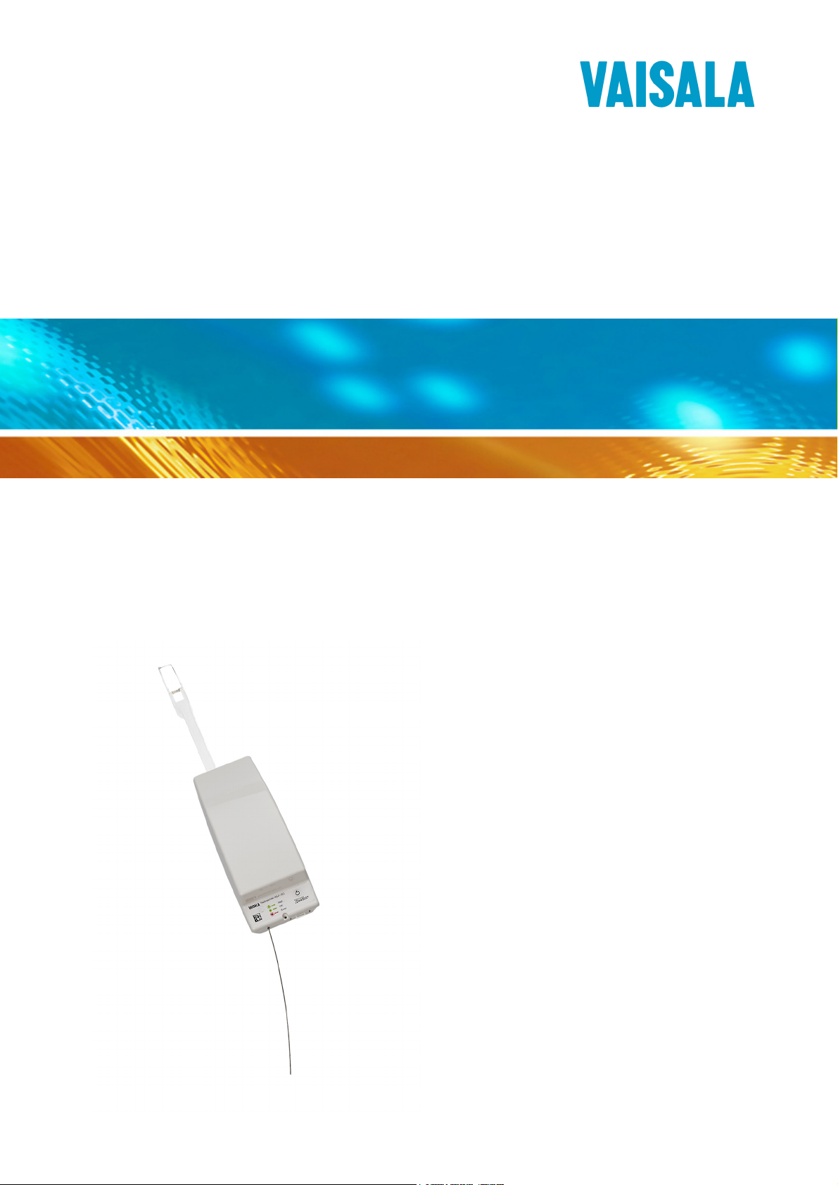
USER'S GUIDE
Vaisala Radiosonde
RS41-SG
M211667EN-A
Page 2

PUBLISHED BY
Vaisala Oyj Phone (int.): +358 9 8949 1
P.O. Box 26 Fax: +358 9 8949 2227
FIN-00421 Helsinki
Finland
Visit our Internet pages at http://www.vaisala.com/
© Vaisala 2013
No part of this manual may be reproduced in any form or by any means,
electronic or mechanical (including photocopying), nor may its contents
be communicated to a third party without prior written permission of the
copyright holder.
The contents are subject to change without prior notice.
Please observe that this manual does not create any legally binding
obligations for Vaisala towards the customer or end user. All legally
binding commitments and agreements are included exclusively in the
applicable supply contract or Conditions of Sale.
Page 3

________________________________________________________________________________
Table of Contents
CHAPTER 1
GENERAL INFORMATION . . . . . . . . . . . . . . . . . . . . . . . . . . . . . . . . . . . . . .7
About This Manual . . . . . . . . . . . . . . . . . . . . . . . . . . . . . . . . .7
Contents of This Manual . . . . . . . . . . . . . . . . . . . . . . . . . . . 7
Version Information . . . . . . . . . . . . . . . . . . . . . . . . . . . . . . . 8
Related Manuals . . . . . . . . . . . . . . . . . . . . . . . . . . . . . . . . . 8
Documentation Conventions . . . . . . . . . . . . . . . . . . . . . . . .8
Product-Related Safety Precautions . . . . . . . . . . . . . . . . . . . 9
ESD Protection . . . . . . . . . . . . . . . . . . . . . . . . . . . . . . . . . . 9
Lithium Battery-Related Precautions . . . . . . . . . . . . . . . . . 10
Recycling . . . . . . . . . . . . . . . . . . . . . . . . . . . . . . . . . . . . . . . . 11
Regulatory Compliances . . . . . . . . . . . . . . . . . . . . . . . . . . . 11
Trademarks . . . . . . . . . . . . . . . . . . . . . . . . . . . . . . . . . . . . . . 11
CHAPTER 2
PRODUCT OVERVIEW . . . . . . . . . . . . . . . . . . . . . . . . . . . . . . . . . . . . . . . 13
Introduction to Vaisala Radiosonde RS41-SG . . . . . . . . . .13
RS41 Unwinder . . . . . . . . . . . . . . . . . . . . . . . . . . . . . . . . . 14
CHAPTER 3
OPERATION . . . . . . . . . . . . . . . . . . . . . . . . . . . . . . . . . . . . . . . . . . . . . . . .17
General . . . . . . . . . . . . . . . . . . . . . . . . . . . . . . . . . . . . . . . . . . 17
Preparing the Sounding with Ground Check Device
RI41 . . . . . . . . . . . . . . . . . . . . . . . . . . . . . . . . . . . . . . . . . . . . 18
Checking RS41 LED Light . . . . . . . . . . . . . . . . . . . . . . . . . . 21
Preparing RS41 Unwinder . . . . . . . . . . . . . . . . . . . . . . . . . . 22
CHAPTER 4
STORAGE AND TRANSPORTATION . . . . . . . . . . . . . . . . . . . . . . . . . . . .27
Storage . . . . . . . . . . . . . . . . . . . . . . . . . . . . . . . . . . . . . . . . . . 27
Transportation . . . . . . . . . . . . . . . . . . . . . . . . . . . . . . . . . . . . 28
CHAPTER 5
TECHNICAL SUPPORT . . . . . . . . . . . . . . . . . . . . . . . . . . . . . . . . . . . . . . . 31
Product Returns . . . . . . . . . . . . . . . . . . . . . . . . . . . . . . . . . . 31
Technical Support . . . . . . . . . . . . . . . . . . . . . . . . . . . . . . . . .31
APPENDIX A
REPLACING RADIOSONDE BATTERIES . . . . . . . . . . . . . . . . . . . . . . . . . 33
VAISALA________________________________________________________________________ 1
Page 4

________________________________________________________________________________
2 ____________________________________________________________________M211667EN-A
Page 5

________________________________________________________________________________
List of Tables
Table 1 Manual Versions . . . . . . . . . . . . . . . . . . . . . . . . . . . . . . . . . . . . .8
Table 2 Related Manuals . . . . . . . . . . . . . . . . . . . . . . . . . . . . . . . . . . . . . 8
Table 3 Unwinder Properties. . . . . . . . . . . . . . . . . . . . . . . . . . . . . . . . . . . 14
Table 4 RS41 LED Lights . . . . . . . . . . . . . . . . . . . . . . . . . . . . . . . . . . . . . 21
VAISALA________________________________________________________________________ 3
Page 6

________________________________________________________________________________
4 ____________________________________________________________________M211667EN-A
Page 7

________________________________________________________________________________
List of Figures
Figure 1 Vaisala Radiosonde RS41-SG with Unwinder . . . . . . . . . . . . . 15
Figure 2 RS41 Unwinder . . . . . . . . . . . . . . . . . . . . . . . . . . . . . . . . . . . . 16
Figure 3 Ground Check Device RI41 . . . . . . . . . . . . . . . . . . . . . . . . . . .18
Figure 4 Do Not Touch the Radiosonde Sensors. . . . . . . . . . . . . . . . . . 19
Figure 5 Radiosonde RS41 Placed on RI41 . . . . . . . . . . . . . . . . . . . . . 19
Figure 6 RS41 Unwinder . . . . . . . . . . . . . . . . . . . . . . . . . . . . . . . . . . . . 22
Figure 7 Unwinder Stick Attached to the Unwinder Bottom Plate . . . . .23
Figure 8 Pushing the Unwinder to Place . . . . . . . . . . . . . . . . . . . . . . . . 24
Figure 9 Unwinder Stick Locking into Place . . . . . . . . . . . . . . . . . . . . . . 24
Figure 10 Lithium Battery Handling Label . . . . . . . . . . . . . . . . . . . . . . . .29
Figure 11 Do Not Touch the Radiosonde Sensors. . . . . . . . . . . . . . . . . . 34
Figure 12 Opening the Radiosonde Cover. . . . . . . . . . . . . . . . . . . . . . . . 34
Figure 13 Opening the Snap Locks . . . . . . . . . . . . . . . . . . . . . . . . . . . . . 35
Figure 14 Opening the Radiosonde Cover. . . . . . . . . . . . . . . . . . . . . . . . 35
Figure 15 RS41 Batteries in the Battery Holder . . . . . . . . . . . . . . . . . . . . 36
Figure 16 RS41 Battery Holder Polarity Symbols . . . . . . . . . . . . . . . . . . 37
Figure 17 RS41 Battery Holder Spring Clip . . . . . . . . . . . . . . . . . . . . . . . 38
Figure 18 Placing Radiosonde Sensor Boom . . . . . . . . . . . . . . . . . . . . . 39
Figure 19 Replacing Radiosonde Cover . . . . . . . . . . . . . . . . . . . . . . . . . 39
Figure 20 Snapping Radiosonde Covers Together . . . . . . . . . . . . . . . . . 40
VAISALA________________________________________________________________________ 5
Page 8

________________________________________________________________________________
6 ____________________________________________________________________M211667EN-A
Page 9

Chapter 1 ________________________________________________________ General Information
CHAPTER 1
GENERAL INFORMATION
This chapter provides general notes for the manual and the product.
About This Manual
This manual provides information for operating Vaisala Radiosonde
RS41-SG. For information on preparing the balloon and optional
sounding accessories, see Vaisala Guide to Sounding Preparations,
Technical Reference. For information on sounding software MW41, see
the on-line help, embedded in the sounding software.
Contents of This Manual
This manual consists of the following chapters:
- Chapter 1, General Information: This chapter provides general
notes for the manual and the product.
- Chapter 2, Product Overview: This chapter introduces the features
and advantages of the radiosonde.
- Chapter 3, Operation: This chapter contains information that is
needed to operate this product.
- Chapter 4, Storage and Transportation: This chapter provides
information for the transport and storage of the product.
VAISALA________________________________________________________________________ 7
Page 10
User's Guide ______________________________________________________________________
- Chapter 5, Technical Support: This chapter presents information
about the failure report and radiosonde warranty.
- Appendix A, Replacing Radiosonde Batteries: This appendix
provides information on replacing radiosonde batteries.
Version Information
Table 1 Manual Versions
Manual Code Description
M211667EN-A October 2013. First version.
Related Manuals
Table 2 Related Manuals
WARNING
CAUTION
Manual Code Manual Name
M211367EN Vaisala Guide to Sounding Preparations Technical
Reference
M211429EN Vaisala DigiCORA Sounding System MW41 Getting
Started Guide
Documentation Conventions
Throughout the manual, important safety considerations are highlighted
as follows:
Warning alerts you to a serious hazard. If you do not read and follow
instructions very carefully at this point, there is a risk of injury or even
death.
Caution warns you of a potential hazard. If you do not read and follow
instructions carefully at this point, the product could be damaged or
important data could be lost.
NOTE
8 ____________________________________________________________________M211667EN-A
Note highlights important information on using the product.
Page 11
Chapter 1 ________________________________________________________ General Information
Product-Related Safety Precautions
WARNING
WARNING
WARNING
CAUTION
CAUTION
Conduct soundings in a safe environment and in accordance with all
applicable restrictions and regulations.
Do not use the radiosonde in an area with power lines or other
obstructions overhead. Make sure that you check the area for such
obstructions before using the radiosonde.
Do not use the radiosonde without consultation and cooperation with
local and other applicable aviation authorities.
Do not modify the unit. Improper modification can damage the
product or lead to malfunction.
Do not use the radiosonde for any purpose other than for soundings.
ESD Protection
Electrostatic Discharge (ESD) can cause immediate or latent damage to
electronic circuits. Vaisala products are adequately protected against
ESD for their intended use. It is possible to damage the product,
however, by delivering electrostatic discharges when touching,
removing, or inserting any objects inside the equipment housing.
To make sure you are not delivering high static voltages yourself:
- Handle ESD sensitive components on a properly grounded and
protected ESD workbench.
- When an ESD workbench is not available, ground yourself to the
equipment chassis with a wrist strap and a resistive connection
cord.
VAISALA________________________________________________________________________ 9
Page 12
User's Guide ______________________________________________________________________
- If you are unable to take either of the above precautions, touch a
conductive part of the equipment chassis with your other hand
before touching ESD sensitive components.
- Always hold component boards by the edges and avoid touching
the component contacts.
Lithium Battery-Related Precautions
CAUTION
Do not place the lithium battery in fire or apply heat to the battery.
Do not pierce the battery with nails, strike the battery with a hammer,
step on the battery, or otherwise damage the outer casing.
Do not subject the battery pack to strong impacts or shocks.
Do not expose the battery to water or salt water, or allow the battery to
get wet.
Do not disassemble or modify the battery. The battery contains safety
and protection devices which, if damaged, may cause the battery to
generate heat, rupture or ignite.
Do not leave the battery in direct sunlight, or use or store the battery
inside cars in hot weather. Doing so may cause the battery to generate
heat, rupture, or ignite. Using the battery in this manner may also result
in shortened life expectancy and loss of performance.
Never short circuit, reverse polarity, disassemble, damage, or heat the
battery over 100 ºC (212 ºF). If an exposed lithium battery does not
start on fire, it will burn even more violently if it comes into contact
with water or even moisture in the air.
DO NOT THROW WATER ON A BURNING BATTERY. A fire
extinguisher must be used.
10 ___________________________________________________________________M211667EN-A
Page 13
Chapter 1 ________________________________________________________ General Information
Recycle all applicable material.
Dispose of batteries and the unit according to statutory regulations.
Do not dispose of with regular household refuse.
Recycling
Regulatory Compliances
Vaisala Radiosonde RS41-SG complies with the following
performance and environmental test standards:
Trademarks
- 2004/108/EC Electromagnetic Compliance:
EN 61000-4-2, EN 61000-4-3 and EN 55022 / EN 302 054-2
- ERM Electromagnetic Compatibility and Radio Spectrum Matters:
ETSI EN 302054-1 and ETSI EN 302054-2
- RoHS compliance:
RoHS Directive (2011/65/EC)
DigiCORA® is a registered trademark of Vaisala Oyj.
VAISALA_______________________________________________________________________ 11
Page 14

User's Guide ______________________________________________________________________
12 ___________________________________________________________________M211667EN-A
Page 15

Chapter 2 __________________________________________________________ Product Overview
CHAPTER 2
PRODUCT OVERVIEW
This chapter introduces the features and advantages of the radiosonde.
Introduction to Vaisala Radiosonde RS41-SG
Vaisala Radiosonde RS41-SG offers excellent data availability and
accuracy of humidity, temperature, pressure, and wind measurement.
The radiosonde is fast and stable with individual, SI-standard traceable
calibration.
Vaisala Radiosonde RS41 temperature sensor utilizes linear resistive
platinum technology. The small size of the sensor results in low solar
radiation error and guarantees fast response. Wind data, height and
pressure are derived from Vaisala Radiosonde RS41-SG GPS data
combined with differential corrected GPS data from MW41 ground
station.
Robust design, Physical Zero Humidity Check and In-built Functional
Temperature Check ensure reliable performance in every situation. The
radiosonde is also easy to use. For example, there is no need for the user
to connect the batteries to the radiosonde to activate it. The radiosonde
is automatically activated when placed on Ground Check Device RI41
or GC41. To make it easier to check the status of the radiosonde,
Radiosonde RS41-SG has LED light indicators visible on the cover. See
Figure 1 on page 15 for an illustration of RS41 with unwinder.
VAISALA_______________________________________________________________________ 13
Page 16

User's Guide ______________________________________________________________________
RS41 Unwinder
The unwinder is specifically designed for use with Radiosonde RS41.
The unwinder is installed to the radiosonde so that it bends the sensor
boom to the correct sounding position, ensuring repeatable results in the
soundings. See Figure 2 on page 16 for an illustration of the unwinder.
Table 3 Unwinder Properties
Material of the string Non-UV treated polypropylene
Tenacity <115 N
Length of the string 30 m
Unwinder weight with stick 24 g
The unwinders are shipped in the radiosonde package, packed
separately from the radiosondes. This allows the operator to prepare the
balloon with the unwinder and the stick attached to it at a time that is
most convenient. The unwinder is connected to the radiosonde by
attaching the stick to its place and, while it is being attached, the stick
bends the sensor boom to the sounding position.
14 ___________________________________________________________________M211667EN-A
Page 17

Chapter 2 __________________________________________________________ Product Overview
0705-015
Figure 1 Vaisala Radiosonde RS41-SG with Unwinder
1 = Sensor boom
2 = Power switch
3 = Additional sensor interface connector
4=Antenna
5 = LED light
6 = Unwinder
7 = Unwinder stick
VAISALA_______________________________________________________________________ 15
Page 18

User's Guide ______________________________________________________________________
1309-228
Figure 2 RS41 Unwinder
16 ___________________________________________________________________M211667EN-A
Page 19

Chapter 3 ________________________________________________________________ Operation
CHAPTER 3
OPERATION
This chapter contains information that is needed to operate this product.
General
It is essential that you carry out the pre-launch steps as instructed and
always in the same way.
The workorder for a sounding is as follows:
1. Unpack and prepare the balloon, the unwinder and the optional
sounding accessories.
2. Unpack and prepare the radiosonde with the ground check device.
3. Attach the unwinder to the radiosonde.
4. Launch the radiosonde.
5. Monitor the sounding with the sounding system.
The following sections include information on preparing the radiosonde
for the sounding with Ground Check Device RI41. For detailed
information on other sounding preparation phases, such as preparing the
optional sounding accessories, see Vaisala Guide to Sounding
Preparations, Technical Reference. For information on configuring the
sounding system software, see Vaisala DigiCORA Sounding System
Getting Started Guide and the on-line help.
VAISALA_______________________________________________________________________ 17
Page 20

User's Guide ______________________________________________________________________
Preparing the Sounding with Ground Check Device RI41
In the sounding preparations, RI41 is connected to the sounding
workstation PC via a USB cable and operated with the help of the
sounding software. RI41 is switched on by connecting it to the sounding
system and turning on the sounding workstation PC.
For information on configuring RI41 as the ground check option in the
sounding software, see the MW41 on-line help. The on-line help also
provides information on other options for preparing the radiosonde for
the sounding.
Figure 3 Ground Check Device RI41
18 ___________________________________________________________________M211667EN-A
Page 21

Chapter 3 ________________________________________________________________ Operation
CAUTION
Do not touch the radiosonde sensors, they are fragile and can be easily
contaminated.
1309-231
Figure 4 Do Not Touch the Radiosonde Sensors
Follow the steps below to prepare the radiosonde for a sounding with
RI41:
1. Place the radiosonde on RI41 carefully. Make sure that the
radiosonde sensor boom does not hit the support plate on RI as this
might damage the sensor boom.
The radiosonde is automatically switched on when placed on RI41.
1309-2
Figure 5 Radiosonde RS41 Placed on RI41
VAISALA_______________________________________________________________________ 19
Page 22

User's Guide ______________________________________________________________________
2. The sounding software automatically detects the radiosonde and
begins the sounding preparations.
The sounding software goes through reconditioning and ground
check. The status is clearly indicated with a progress bar. During
the ground check, the following preparation steps are performed
for the radiosonde:
- T check: The radiosonde performs an in-built functional
temperature check.
- Reconditioning: Preparation of humidity sensor.
- Cooling after reconditioning
- U check: The radiosonde performs a physical zero humidity
check.
3. After the ground check is finished, the sounding software indicates
the results with a message. Remove the radiosonde from RI41.
Before the radiosonde is launched, you can return to the
preparation phase anytime by replacing the radiosonde on RI41.
The sounding software automatically returns to the ground check
phase.
If there is any delay in starting the sounding, for example, if you
must wait before launching the sounding balloon, you can switch
the radiosonde off by pressing the power switch. When you are
ready to launch the balloon, switch the radiosonde back on.
4. After radiosonde launch, proceed to monitor the sounding with the
sounding software.
20 ___________________________________________________________________M211667EN-A
Page 23

Chapter 3 ________________________________________________________________ Operation
Checking RS41 LED Light
After preparing radiosonde RS41 for the sounding, check the
radiosonde GPS reception by checking the LED light on the radiosonde
cover. RS41 LED light will switch off automatically after the launch.
Table 4 RS41 LED Lights
Green LED is blinking. When the green LED light is blinking,
the reconditioning of the humidity
sensor and sensor checks are in
progress and/or GPS signal has not
been detected after the radiosonde
startup. To receive the GPS signal,
take the radiosonde outside with line
of sight to GPS satellites.
Green LED is lit and burns steadily. 1. The radiosonde is ready and
works fine, determined by the
radiosonde self diagnostics.
The self diagnostics cover, for
example, temperature and humidity
sensors, as well as GPS.
2. GPS satellites are detected. Once
GPS signal has been found after
radiosonde start up, the LED light
becomes steady green. The LED
stays steady green despite possible
GPS blind spots (for example, inside
the balloon shelter), indicating that
the GPS feature has been diagnosed
to be OK.
3. The steady green LED light
indicates that the telemetry from
RS41 is working.
Red LED is lit. Error. For possible battery
replacement, see Appendix A
Replacing Radiosonde Batteries on
page 33.
NOTE
Even though the radiosonde LED light is steady green and the
telemetry is working, it does not necessarily indicate that MW41
sounding software receives data from the radiosonde. Always make
sure that the sounding software receives the data.
VAISALA_______________________________________________________________________ 21
Page 24

User's Guide ______________________________________________________________________
Preparing RS41 Unwinder
To start using the RS41 unwinder, first detach the unwinder stick
(number 1 in Figure 6 on page 22) from the unwinder body. The stick is
attached between two plastic clips in the unwinder hook (number 2).
Detach the stick from between the plastic clips and pull it out from the
unwinder bottom plate (3).
If the unwinder stick is tightly attached to the bottom plate, it is a good
idea to slightly twist the unwinder stick before pulling it out. When you
pull the unwinder stick out, make sure that the string unwinds and that
it is not tangled. Also make sure that the string does not unwind too
much. See Figure 7 on page 23 for a suggestion of how to keep the string
from unwinding too much.
In the unwinder body, the unwinder string runs under a round plastic
clip (4) on the bottom plate. This will keep the string attached to the
unwinder, and the radiosonde attached to the balloon.
1308-052
Figure 6 RS41 Unwinder
To prevent the string from getting tangled in the clip, make sure the
round plastic clip (number 4) is level with the unwinder bottom plate. If
the lip is bent, bend it gently back to level position but be careful not the
bend it above the bottom plate.
22 ___________________________________________________________________M211667EN-A
Page 25

Chapter 3 ________________________________________________________________ Operation
One way of avoiding the unwinder string from unwinding too much and
getting tangled is to attach the unwinder stick to the hole in the bottom
plate. See Figure 7 on page 23 for an illustration.
Figure 7 Unwinder Stick Attached to the Unwinder Bottom
Plate
VAISALA_______________________________________________________________________ 23
Page 26

User's Guide ______________________________________________________________________
Before launching the radiosonde, bend the sensor boom to the correct
sounding position using the unwinder stick: push the unwinder stick to
its position at the end of the radiosonde. As you push, the unwinder
stick pushes the sensor boom to the bent position and the unwinder snap
lock clicks into place. Make sure that the unwinder is firmly attached to
the radiosonde. See Figure 8 on page 24 and Figure 9 on page 24.
308-035
Figure 8 Pushing the Unwinder to Place
1308-037
Figure 9 Unwinder Stick Locking into Place
24 ___________________________________________________________________M211667EN-A
Page 27

Chapter 3 ________________________________________________________________ Operation
If necessary, push the unwinder stick in two places: hold the radiosonde
in your left hand and push the stick with your thumb as shown in Figure
9 on page 24. Use your right hand thumb to push the stem of the stick
against the edge of the radiosonde.
Make sure that the unwinder string does not unwind too much at this
stage. It might get tangled during the preparations.
VAISALA_______________________________________________________________________ 25
Page 28

User's Guide ______________________________________________________________________
26 ___________________________________________________________________M211667EN-A
Page 29

Chapter 4 __________________________________________________ Storage and Transportation
CHAPTER 4
STORAGE AND TRANSPORTATION
This chapter provides information for the transport and storage of the
product.
Storage
CAUTION
Radiosondes must be stored and used properly in accordance with
applicable instructions, the User’s Guide, and specifications issued by
Vaisala.
Proper storage conditions must fulfill the following requirements:
Radiosondes must be kept in their original packaging (unopened
vacuum envelopes) in a dry, ventilated indoor storage space, and within
the following key environmental limits (ref. IEC 60721-3-1 class 1K2):
- Temperature +5 °C to +40 °C
- Relative humidity below 85%
The suspension string is not resistant to prolonged exposure to
sunlight. Store the unwinders in their original unopened packages.
VAISALA_______________________________________________________________________ 27
Page 30

User's Guide ______________________________________________________________________
Transportation
Vaisala radiosondes must be transported in their original shipping
packages. These packages are designed and built to survive and protect
their contents in the environmental conditions described herein with the
terminology and standards per standard: IEC 60721-3-2. The
transportation of radiosondes requires climatic conditions 2K2 and
mechanical conditions 2M1 of this standard:
- Transportation in weather-protected conditions.
- Transportation using conventional means (car, truck, and/or
aircraft), with free fall not exceeding 0.25 m in any circumstances.
- Following additional markings on packaging.
Transporting RS41 Radiosondes with Lithium Batteries
RS41 radiosondes with lithium batteries are classified as:
- UN 3091 Lithium metal batteries packed with equipment
Consignments must be packed, labeled, and documented according to
the IATA packing instructions.
When transporting the radiosondes with lithium batteries, take the
following requirements into account:
- The package must display a lithium battery handling label, see
Figure 10 on page 29 for an example. The original radiosonde
shipping package must be used for transport, and it already has the
lithium battery handling label.
- The consignment must include a document indicating the lithium
content, describing proper handling and procedures for damaged
packages, and a telephone number for additional information. The
original radiosonde consignment includes a SHIPPER'S
DECLARATION FOR ARTICLES NOT REGULATED AS
DANGEROUS GOODS, which should be reused for this purpose
after updating the appropriate information.
28 ___________________________________________________________________M211667EN-A
Page 31

Chapter 4 __________________________________________________ Storage and Transportation
1002-100
Figure 10 Lithium Battery Handling Label
NOTE
If the lithium battery is faulty, do not transport it.
VAISALA_______________________________________________________________________ 29
Page 32

User's Guide ______________________________________________________________________
30 ___________________________________________________________________M211667EN-A
Page 33

Chapter 5 _________________________________________________________ Technical Support
CHAPTER 5
TECHNICAL SUPPORT
This chapter presents information about technical support.
Product Returns
If the product is found faulty, please follow the instructions below to
speed up the process and to avoid extra costs to you.
1. Read the radiosonde warranty information.
2. Contact Vaisala technical support via e-mail or fax and request for
RMA (Return Material Authorization) and shipping instructions.
3. Proceed as instructed by Vaisala technical support and provide the
failure report as requested.
NOTE
RMA must always be requested from Vaisala technical support before
returning any faulty material.
Technical Support
For technical questions, contact the Vaisala technical support:
E-mail helpdesk@vaisala.com
Fax +358 9 8949 2790
VAISALA_______________________________________________________________________ 31
Page 34

User's Guide ______________________________________________________________________
32 ___________________________________________________________________M211667EN-A
Page 35

Appendix A _____________________________________________ Replacing Radiosonde Batteries
APPENDIX A
REPLACING RADIOSONDE BATTERIES
This appendix provides information on replacing the radiosonde
batteries.
NOTE
CAUTION
Note that inserting or replacing radiosonde batteries is not part of the
normal operation of the radiosonde. It is only needed in a possible error
situation indicated by the radiosonde or the ground equipment.
RS41-SG uses two lithium batteries which have power for
approximately five hours.
If the radiosonde LED light indicator is red and MW41 sounding system
gives a warning on low battery capacity during the radiosonde ground
check, you must replace the radiosonde batteries.
To replace the batteries, follow the steps below. You can use, for
example, a small screwdriver to open the radiosonde cover.
Do not touch the radiosonde sensors, they are fragile and can be easily
contaminated. Handle the radiosonde carefully and do not let the
sensors touch anything while changing the batteries.
VAISALA_______________________________________________________________________ 33
Page 36

User's Guide ______________________________________________________________________
1309-231
Figure 11 Do Not Touch the Radiosonde Sensors
1. Loosen the radiosonde cover by placing the tip of the screwdriver
to the small slots at the antenna end of the radiosonde and twist the
screwdriver carefully. See Figure 12 on page 34 for an example. At
the same time, slightly press the sides of the bottom half of the
radiosonde to loosen the snap locks. See Figure 13 on page 35.
1310-003
Figure 12 Opening the Radiosonde Cover
34 ___________________________________________________________________M211667EN-A
Page 37

Appendix A _____________________________________________ Replacing Radiosonde Batteries
1310-004
Figure 13 Opening the Snap Locks
CAUTION
Be careful not to accidentally touch the pins in the additional sensor
interface connector with the screwdriver, you might short circuit the
radiosonde.
2. Open the radiosonde cover by lifting the antenna end first and
remove the styrofoam case from inside the radiosonde.
1310-005
Figure 14 Opening the Radiosonde Cover
3. The battery holder is inside the styrofoam case, on top of a PCB
board. To make the changing of batteries easier, you can remove
the PCB board and the battery holder from inside the radiosonde
bottom cover, but be careful not to touch the Printed Circuit Board
(PCB).
VAISALA_______________________________________________________________________ 35
Page 38

User's Guide ______________________________________________________________________
CAUTION
Do not touch the PCB board. You might deliver electrostatic discharge
and damage the radiosonde.
1310-006
Figure 15 RS41 Batteries in the Battery Holder
4. Remove the old batteries from the battery holder.
36 ___________________________________________________________________M211667EN-A
Page 39

Appendix A _____________________________________________ Replacing Radiosonde Batteries
5. Before placing the new batteries, check the battery polarity
symbols on the radiosonde battery holder carefully. See Figure 16
on page 37 for an illustration of RS41 battery holder polarity
symbols.
CAUTION
Make sure to check the battery polarity symbols in the battery holder
carefully and to place the new batteries correctly. Placing both battery
poles in the wrong direction damages the radiosonde. Placing one
battery pole in the wrong direction prevents the radiosonde from
working.
1310-007
Figure 16 RS41 Battery Holder Polarity Symbols
VAISALA_______________________________________________________________________ 37
Page 40

User's Guide ______________________________________________________________________
6. When placing the new batteries, it is easier to insert the batteries by
first pushing them against the spring clips, circled in Figure 17 on
page 38.
1310-009
Figure 17 RS41 Battery Holder Spring Clip
7. Put the battery holder and the PCB board back inside the styrofoam
bottom case and put the styrofoam cover back on.
38 ___________________________________________________________________M211667EN-A
Page 41

Appendix A _____________________________________________ Replacing Radiosonde Batteries
8. Put the styrofoam case back inside the radiosonde bottom cover.
Check the positioning of the sensor boom: Make sure the small
hole at the stem of the sensor boom meets the white pin on the edge
of the radiosonde cover. Use your thumb to push the stem of the
sensor boom, if necessary, but do not touch the sensors.
1310-008
Figure 18 Placing Radiosonde Sensor Boom
9. Replace the radiosonde cover by first attaching the three hooks at
the sensor end of the radiosonde and then setting the rest of the
cover down.
Figure 19 Replacing Radiosonde Cover
VAISALA_______________________________________________________________________ 39
Page 42

User's Guide ______________________________________________________________________
10. Snap the radiosonde covers together and make sure the that the
three snap locks on both sides of the radiosonde are locked. Check
all the seams to make sure that the radiosonde covers are tightly
attached.
NOTE
1310-010
Figure 20 Snapping Radiosonde Covers Together
11. Even after changing the batteries, the radiosonde LED light
indicator remains red and the sounding software gives a warning
on low battery capacity and a short sounding time. However, if
these are the only warnings you get, you can start a sounding after
changing the batteries and the radisonde works as usual.
The radiosonde LED light indicator remains red and the sounding
software gives a warning on low battery capacity after replacing the
batteries. However, if these are the only warnings you get, you can
start a sounding after changing the batteries.
40 ___________________________________________________________________M211667EN-A
Page 43

Page 44

*M211667EN*
www.vaisala.com
 Loading...