

Page 1
M211861EN-A
User Guide
Vaisala VaiNet Wireless Humidity and
Temperature Data Logger
RFL100
Page 2

PUBLISHED BY
Vaisala Oyj
Street address: Vanha Nurmijärventie 21, FI-01670 Vantaa, Finland
Mailing address: P.O. Box 26, FI-00421 Helsinki, Finland
Phone: +358 9 8949 1
Visit our Internet pages at www.vaisala.com.
© Vaisala 2018
No part of this manual may be
reproduced, published or publicly
displayed in any form or by any
means, electronic or mechanical
(including photocopying), nor
may its contents be modified,
translated, adapted, sold or
disclosed to a third party without
prior written permission of the
copyright holder. Translated
manuals and translated portions
of multilingual documents are
based on the original English
versions. In ambiguous cases, the
English versions are applicable,
not the translations.
The contents of this manual are
subject to change without prior
notice.
Local rules and regulations may
vary and they shall take
precedence over the information
contained in this manual. Vaisala
makes no representations on this
manual’s compliance with the
local rules and regulations
applicable at any given time, and
hereby disclaims any and all
responsibilities related thereto.
This manual does not create any
legally binding obligations for
Vaisala towards customers or end
users. All legally binding
obligations and agreements are
included exclusively in the
applicable supply contract or the
General Conditions of Sale and
General Conditions of Service of
Vaisala.
This product contains software
developed by Vaisala or third
parties. Use of the software is
governed by license terms and
conditions included in the
applicable supply contract or, in
the absence of separate license
terms and conditions, by the
General License Conditions of
Vaisala Group.
This product may contain open
source software (OSS)
components. In the event this
product contains OSS
components, then such OSS is
governed by the terms and
conditions of the applicable OSS
licenses, and you are bound by
the terms and conditions of such
licenses in connection with your
use and distribution of the OSS in
this product. Applicable OSS
licenses are included in the
product itself or provided to you
on any other applicable media,
depending on each individual
product and the product items
delivered to you.
Page 3

Table of Contents
Table of Contents
1. About This Document................................................................................... 5
1.1 Version Information..........................................................................................5
1.2 Related Manuals................................................................................................5
1.3 Documentation Conventions...........................................................................5
1.4 Trademarks........................................................................................................ 6
2. Product Overview........................................................................................... 7
2.1 RFL100 Overview..............................................................................................7
2.2 RFL100 Parts..................................................................................................... 8
2.3 RFL100 Batteries.............................................................................................10
2.3.1 Battery Level Indicator............................................................................10
2.4 Alarm Indicators............................................................................................... 11
2.4.1 Alarm Examples........................................................................................12
2.5 Service Port......................................................................................................13
2.6 Delays in a VaiNet Network............................................................................13
2.7 Regulatory Compliance..................................................................................14
2.7.1 FCC Compliance Statement....................................................................14
2.7.2 ISED Compliance Statement...................................................................15
2.7.3 EU Declaration of Conformity.................................................................15
2.8 Safety................................................................................................................ 17
2.9 Symbols in RFL100 Product Markings.......................................................... 17
2.10 ESD Protection.................................................................................................18
3. Installation........................................................................................................19
3.1 Setting Up RFL100 Data Logger....................................................................19
3.2 Mounting RFL100...........................................................................................20
3.3 Connection Indicators....................................................................................22
3.3.1 Connection Examples............................................................................. 23
4. Operation......................................................................................................... 24
4.1 Remote Management.....................................................................................24
4.2 Releasing RFL100 from a viewLinc Monitoring System.............................25
4.3 Speeding Up Radio Scanning Temporarily..................................................26
5. Maintenance....................................................................................................28
5.1 Cleaning RFL100.............................................................................................28
5.2 Changing the Probe Filter............................................................................. 28
5.3 Disconnecting the Probe...............................................................................29
5.4 Connecting the Probe....................................................................................29
5.5 Calibration and Adjustment..........................................................................29
5.5.1 Field Checking Using a Reference Instrument.................................... 30
5.5.2 Calibration and Adjustment Using HM40............................................30
5.5.3 Calibration and Adjustment using MI70...............................................36
5.6 Changing RFL100 Batteries...........................................................................37
5.7 Changing RFL100 Clock Battery...................................................................38
5.8 Updating RFL100 Firmware.......................................................................... 38
1
Page 4

RFL100 User Guide M211861EN-A
6. Troubleshooting............................................................................................40
6.1 Problem Situations........................................................................................ 40
6.2 Error Codes...................................................................................................... 41
6.3 Verifying Operation of RFL100.....................................................................42
6.4 Downloading Data Using Service Port........................................................ 42
7. Technical Data............................................................................................... 44
7.1 RFL100 Technical Specification....................................................................44
7.2 Spare Parts and Accessories.........................................................................48
7.3 RFL100 Dimensions....................................................................................... 49
Technical Support...................................................................................................... 51
Warranty........................................................................................................................ 51
Recycling....................................................................................................................... 51
2
Page 5

List of Figures
Figure 1 Connecting RFL100 to the viewLinc Monitoring System........................ 7
Figure 2 Front and Display...............................................................................................8
Figure 3 Under the Silicone Plug.................................................................................... 8
Figure 4 Rear and Inside................................................................................................... 9
Figure 5 Mounting Bracket...............................................................................................9
Figure 6 Alarm Indicators on RFL100 Display............................................................ 11
Figure 7 RFL100 with High Alarm Active on Channel 1...........................................12
Figure 8 RFL100 with High-High Alarm Active on Channel 1................................12
Figure 9 RFL100 Mounting Methods...........................................................................20
Figure 10 RFL100 Remote Management using viewLinc Enterprise Server...... 24
Figure 11 RFL100 Properties in viewLinc.....................................................................25
Figure 12 RFL100 Data Logger Dimensions with Mounting Bracket...................49
Figure 13 RFL100 Data Logger Dimensions................................................................50
Figure 14 RFL100 Mounting Bracket Dimensions......................................................50
List of Figures
3
Page 6

RFL100 User Guide M211861EN-A
List of Tables
Table 1 Document Versions.............................................................................................5
Table 2 Related Manuals...................................................................................................5
Table 3 Battery Level Indicator.....................................................................................10
Table 4 Alarm Symbols.....................................................................................................11
Table 5 Specifications for a USB Power Supply........................................................13
Table 6 Symbols Used in RFL100 Product Markings...............................................17
Table 7 Symbols................................................................................................................22
Table 8 Connection States.............................................................................................22
Table 9 Troubleshooting Table.....................................................................................40
Table 10 RFL100 Error Codes.......................................................................................... 41
Table 11 Wireless............................................................................................................... 44
Table 12 Memory................................................................................................................44
Table 13 Operating Environment...................................................................................45
Table 14 General.................................................................................................................45
Table 15 Mechanical Specifications.............................................................................. 45
Table 16 HMP110/T Probe Measurement Performance........................................... 46
Table 17 HMP115/T Probe Measurement Performance............................................47
Table 18 RFL100 Spare Parts and Accessories..........................................................48
Table 19 HMP110/T Probe Spare Parts and Accessories......................................... 48
Table 20 HMP115/T Probe Spare Parts and Accessories..........................................49
4
Page 7
Chapter 1 – About This Document
1. About This Document
1.1 Version Information
This document provides instructions for installing, using, and maintaining the RFL100 Data
Logger.
Table 1 Document Versions
Document Code Date Description
M211861EN-A May 2018 First version.
1.2 Related Manuals
Table 2 Related Manuals
Document Code Name
M211822EN RFL100 Data Logger Quick Guide
M211821EN AP10 Access Point Quick Guide
M211860EN AP10 Access Point User Guide
M211820EN viewLinc Monitoring System Setup Guide
M211975EN viewLinc Enterprise Server User Guide
1.3 Documentation Conventions
WARNING!
follow instructions carefully at this point, there is a risk of injury or even death.
CAUTION!
follow instructions carefully at this point, the product could be damaged or
important data could be lost.
Note highlights important information on using the product.
Warning alerts you to a serious hazard. If you do not read and
Caution warns you of a potential hazard. If you do not read and
5
Page 8
RFL100 User Guide M211861EN-A
Tip gives information for using the product more eciently.
Lists tools needed to perform the task.
Indicates that you need to take some notes during the task.
1.4 Trademarks
Vaisalaâ and HUMICAPâ are registered trademarks of Vaisala Oyj.
The LoRa™ name and associated logo are trademarks of Semtech Corporation or its
subsidiaries.
All other product or company names that may be mentioned in this publication are trade
names, trademarks, or registered trademarks of their respective owners.
6
Page 9
viewLinc
Enterprise Server
AP10
Access Point
RFL100
Data Loggers
VaiNet wireless
>100 m (328 ft) range
NTP Server
Wired
network
Chapter 2 – Product Overview
2. Product Overview
2.1 RFL100 Overview
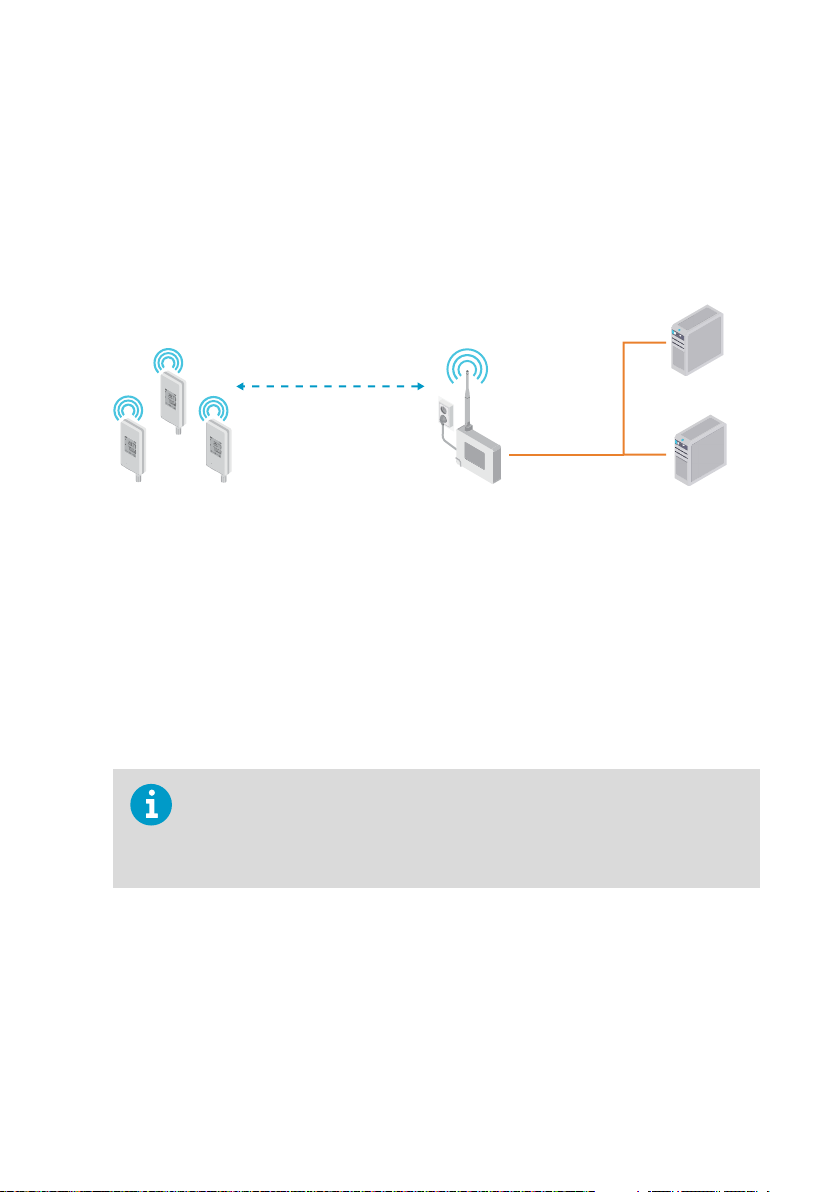
Vaisala RFL100 Data Logger is a completely wireless, battery powered humidity and
temperature data logger. It is intended as a data collection point in a Vaisala viewLinc
Monitoring System.
Figure 1 Connecting RFL100 to the viewLinc Monitoring System
RFL100 requires a connection to a Vaisala AP10 Access Point. AP10 can connect up to 32
loggers to the viewLinc Monitoring System. In a typical indoor space, install the AP10 within
100 meters of the RFL100. In an open space without many interfering structures, the range
significantly higher.
may be
RFL100 is optimized for low power operation. It reads the probe once a minute, and transmits
measurement data to the access point every four minutes. Because the radio link is not
continuous, remote management actions and system joining status may take some time to be
updated on the display of the data logger.
Before you start installing RFL100 Data Loggers, install the viewLinc Enterprise
Server and at least one AP10 Access Point within range of the RFL100. This way
RFL100 can immediately discover your access point and join your system.
For more information on viewLinc Monitoring System installation, see viewLinc
Setup Guide.
7
Page 10
1
2
3
4
5
6
7
8
1
2
RFL100 User Guide M211861EN-A
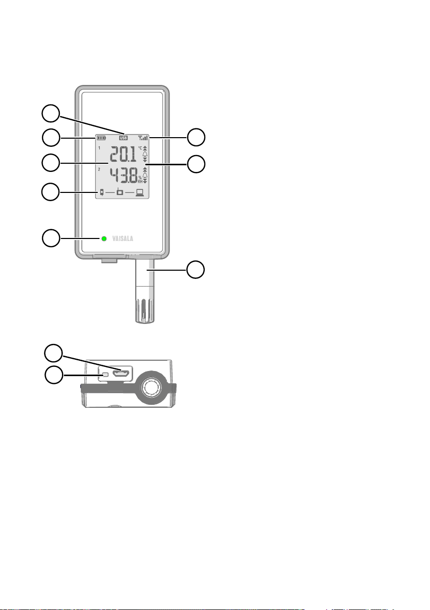
2.2 RFL100 Parts
Figure 2 Front and Display
1 Service port connection indicator.
2 Battery level indicator.
3 Currently measured values.
4 Connection indicators.
5 Status LED. Blinks green for normal
operation, red for error or alarm.
6 Signal strength of access point
connection.
7 Alarm indicators. Alarms are
configured in viewLinc Enterprise
Server software.
8 Detachable probe or probe cable.
Figure 3 Under the Silicone Plug
1 Service port (Micro-USB).
2 Refresh button. Push to enable a faster
wireless scanning interval for one hour.
Also wakes up the display if it has
been turned o remotely, and shows
firmware version and currently
connected VaiNet channel.
8
Page 11
1
2
3
4
5
6
7
8
1
2
5
4
3
2
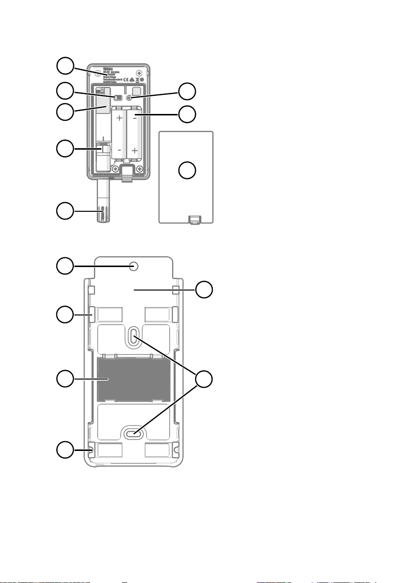
Chapter 2 – Product Overview
Figure 4 Rear and Inside
1 Type label.
2 On/o switch.
3 Clock battery.
4 Probe orientation mark. When
connecting the probe, line up the
markings on the probe and above the
connector before pushing the probe to
the connector.
5 Humidity and/or temperature sensors
under the filter.
6 Release button. Push to release
RFL100 from its current viewLinc
system, and allow it to connect to any
viewLinc system.
7 Main batteries. Use only non-
rechargeable, AA size, 1.5 V alkaline
(LR6) or lithium (FR6) batteries.
8 Battery cover.
Figure 5 Mounting Bracket
1 6 mm (0.23 inch) hole for hook
mounting.
2 Holes for mounting with zip ties.
3 Strong magnet (in magnetic mounting
bracket only). Handle with care.
4 Suitable area for attaching labels.
5 3.80 mm (0.15 inch) holes for screw
mounting.
9
Page 12
RFL100 User Guide M211861EN-A
2.3 RFL100 Batteries
Main Batteries
RFL100 Data Logger is powered by two AA size primary (non-chargeable) batteries with 1.5 V
nominal voltage. Operation of the data logger always requires that compatible batteries with
sucient voltage are in place. When replacing batteries, always use new batteries, not partially
discharged ones. Minimum battery voltage for operation is 2.15 V in series.
Compatible battery types are:
• 1.5 V alkaline batteries, designation IEC-LR6, ANSI 15A. Standard choice for most
applications.
• 1.5 V lithium batteries, designation IEC-FR14505 (FR6), ANSI 15-LF. Typically higher
capacity, better in cold temperatures.
Do not use batteries with a nominal voltage higher than 1.5 V.CAUTION!
Use of rechargeable batteries is not recommended. RFL100 will not charge
batteries even if the service port is connected to a power supply.
Clock Battery
RFL100 also has a separate 3 V lithium battery (type CR1/3N button cell) to keep the real-time
clock powered when the device is otherwise turned o. This battery is good for 10 years, and
should only be replaced if the data logger gives the low clock battery error.
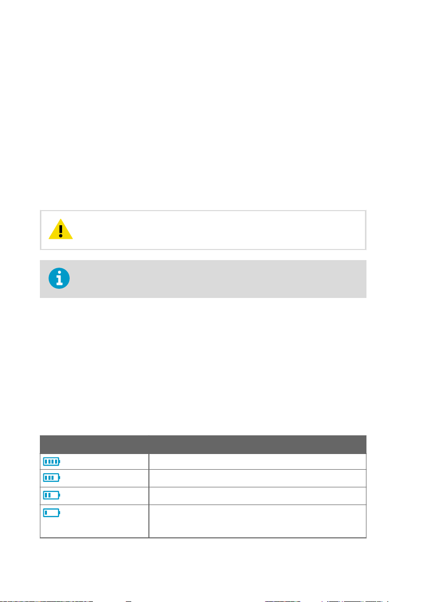
2.3.1 Battery Level Indicator
Battery level indicator displays an estimate of the capacity remaining in the main batteries of
the data logger. It is based on typical behavior of batteries in this application.
Table 3 Battery Level Indicator
Symbol on Display Description
Full batteries.
One quarter of battery capacity used.
Half of the battery capacity used.
Low battery alarm is activated by viewLinc at this level.
Remaining battery capacity is typically enough for 2 … 4 weeks of
normal operation. Replace the batteries.
10
Page 13
Symbol on Display Description
1
2
Battery voltage is too low to support radio communication. Data
logging continues locally for 2 … 4 weeks until device shuts down
completely. Replace batteries immediately.
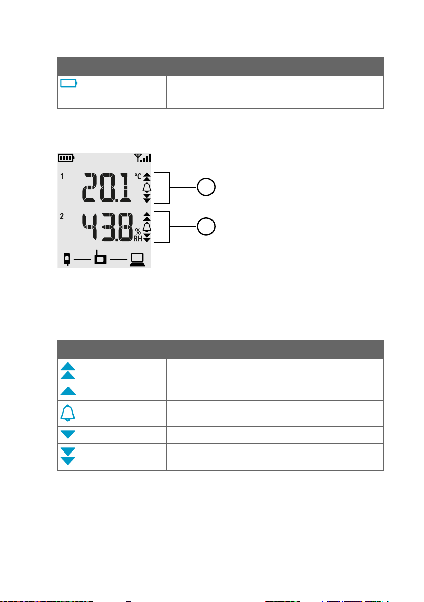
2.4 Alarm Indicators
Figure 6 Alarm Indicators on RFL100 Display
1 Alarm indicators for channel 1
2 Alarm indicators for channel 2
Chapter 2 – Product Overview
Table 4 Alarm Symbols
Symbol on Display Description
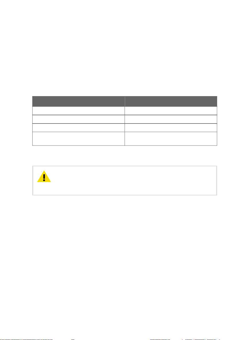
High-high threshold alarm active.
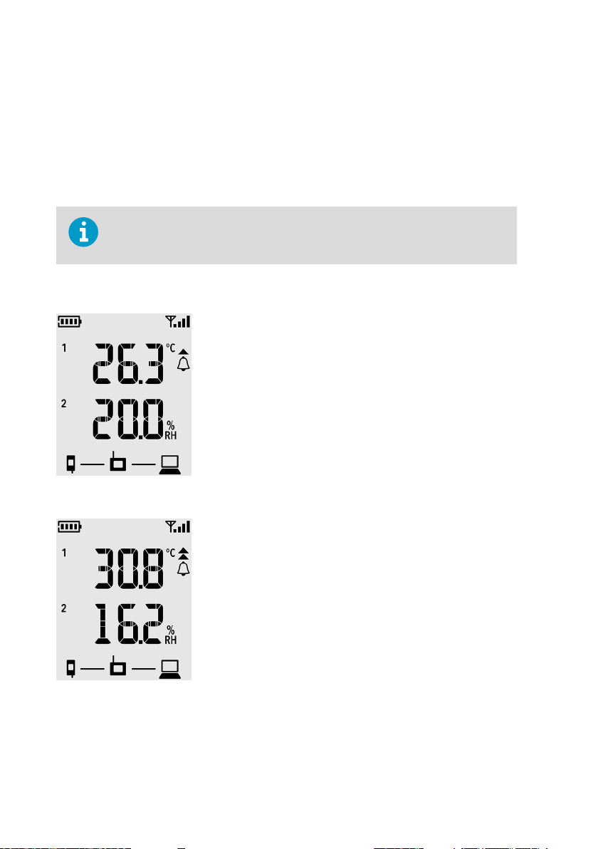
High threshold alarm active.
Alarm bell symbol that is always shown when any threshold
alarm is active on this channel.
Low threshold alarm active.
Low-low threshold alarm active.
RFL100 can show active threshold alarms on its local display. When a threshold alarm is active
on RFL100, the appropriate alarm indicators will be shown on the display. Additionally, the LED
flash red for high-high and low-low threshold alarms.
will
11
Page 14
RFL100 User Guide M211861EN-A
Threshold alarms cannot be configured locally on the RFL100 itself; they are configured using
viewLinc Enterprise Server software. When applying a threshold alarm template to a Location,
you can choose to show the alarms on the data logger that is linked to the location. To show
the alarms, enable the Send to device setting, and then enable Alarm on Device for each
threshold that you want to generate an alarm on the RFL100.
On the RFL100, only one set of thresholds can be active at a time for one channel. The latest
set that is pushed to the device replaces the previous one. The Send to device setting of any
previously sent threshold alarm is automatically set to No.
RFL100 does not implement the Alarm Delay and Alarm o margin settings of
viewLinc threshold alarms. Local alarm status on RFL100 changes as soon as the
measured values cross the thresholds.
2.4.1 Alarm Examples
Figure 7 RFL100 with High Alarm Active on Channel 1
Figure 8 RFL100 with High-High Alarm Active on Channel 1
12
Page 15
Chapter 2 – Product Overview
2.5 Service Port
The service port of the data logger provides a local interface for performing service actions
that cannot be done over the air, such as updating the device firmware. The service actions are
based on file transfer using Media Transfer Protocol (MTP), so no special software is needed.
The service port connector is a standard micro-USB connector.
The service port can be used to supply operating power to the data logger. Use a power
supply that fulfills the requirements listed in Table 5 (page 13).
Table 5 Specifications for a USB Power Supply
Property Specification
Output voltage 5 VDC
Output current min. 100 mA
Output connector Micro-USB
Certifications and approvals • Certified to IEC 60950-1 or IEC 62368-1
Batteries with a sucient voltage must always be in place inside the data logger, even when
supplying external power through the service port.
• Approved for use in your country
CAUTION!
drained very slowly. As alkaline batteries may leak when left in place for a long
time, always use compatible 1.5 V lithium batteries instead of alkaline batteries
when using an external power supply.
When using an external power supply, the main batteries will be
2.6 Delays in a VaiNet Network
VaiNet protocol and VaiNet devices are designed for power-ecient operation. Some of the
design choices that enable long battery life also create significant delays that the users should
be aware of.
Intermittent Radio Connections
Radio connections between VaiNet access points and data loggers are not continuous. Access
points take turns communicating in a two-minute cycle, and connected data loggers send their
measurement data to their connected access point every four minutes. This introduces various
delays:
13
Page 16
RFL100 User Guide M211861EN-A
• Data loggers that are not currently connected (new devices or ones that have fallen out of
radio contact) have to scan for available access points for a complete cycle before they
can decide what is the optimal access point for them. This means that connection
attempts typically take at least a couple of minutes. Additionally, some joining scenarios
may take multiple attempts. For example, when filling a single access point up to its full
capacity of 32 data loggers, it may take an hour for the last data logger to successfully
connect to the access point.
• Access points request missing data and issue management commands to data loggers
within their communication window. Transferring a full month's worth of measurement
data from 32 data loggers using one access point takes several hours.
Data Logger Scanning Interval
Scanning for available access points consumes power. To prevent repeated scanning from
draining their batteries, RFL100 Data Loggers shut down their radio temporarily if they can
find no access points to join. They will resume scanning after a waiting interval that gets
progressively longer if they keep failing to find an access point. The maximum interval is 8
hours and 30 minutes.
This means that when access points become available after an outage, it may take several
hours for data loggers to discover them. This is why you should always keep your access points
powered up, and why you should start your network installation by installing the viewLinc
Enterprise Server and access points
You can manually wake up the radio of an RFL100 Data Logger by pressing its
Refresh button. The button is located next to the service port under the silicone
plug.
first.
2.7 Regulatory Compliance
2.7.1 FCC Compliance Statement
This equipment has been tested and found to comply with the limits for a Class A digital
device, pursuant to part 15 of the FCC Rules. These limits are designed to provide reasonable
protection against harmful interference when the equipment is operated in a commercial
environment. This equipment generates, uses, and can radiate radio frequency energy and, if
not installed and used in accordance with the instruction manual, may cause harmful
interference to radio communications. Operation of this equipment in a residential area is likely
to cause harmful interference in which case the user will be required to correct the interference
at his own expense.
WARNING!
approved by the party responsible for compliance could void the user’s
authority to operate the equipment.
14
Changes or modifications to this equipment not expressly
Page 17
Chapter 2 – Product Overview
WARNING!
subject to the following two conditions: (1) This device may not cause harmful
interference, and (2) this device must accept any interference received,
including interference that may cause undesired operation.
This device complies with part 15 of the FCC Rules. Operation is
2.7.2 ISED Compliance Statement
This device complies with Industry Canada licence-exempt RSS standard(s). Operation is
subject to the following two conditions:
1. This device may not cause interference; and
2. This device must accept any interference, including interference that may cause undesired
operation of the device.
This device has a PCB integrated inverted F-antenna with a gain of 1 dBi.
Le présent appareil est conforme aux CNR d’lndustrie Canada applicables aux appareils radio
exempts de licence. L’exploitation est autorisée aux deux conditions suivantes:
1. l’appareil ne doit pas produire de brouillage, et
2. l’utilisateur de l’appareil doit accepter tout brouillage radioélectrique subi, même si le
brouillage est susceptible d’en compromettre le fonctionnement.
Le présent appareil dispose d'une antenne F inversée intégrée à la carte avec un gain de 1 dBi.
2.7.3 EU Declaration of Conformity
BG: С настоящото Vaisala Oyj декларира, че този тип радиосъоръжение RFL100 е в
съответствие с Директива 2014/53/ЕС. Цялостният текст на ЕС декларацията за
съответствие може да се намери на следния интернет адрес: www.vaisala.com/
declarationofconformity
CS: Tímto Vaisala Oyj prohlašuje, že typ rádiového zařízení RFL100 je v souladu se směrnicí
2014/53/EU. Úplné znění EU prohlášení o shodě je k dispozici na této internetové adrese:
www.vaisala.com/declarationofconformity
DA: Hermed erklærer Vaisala Oyj , at radioudstyrstypen RFL100 er i overensstemmelse med
direktiv 2014/53/EU. EU-overensstemmelseserklæringens fulde tekst kan
internetadresse: www.vaisala.com/declarationofconformity
DE: Hiermit erklärt Vaisala Oyj , dass der Funkanlagentyp RFL100 der Richtlinie 2014/53/EU
entspricht. Der vollständige Text der EU-Konformitätserklärung ist unter der folgenden
Internetadresse verfügbar: www.vaisala.com/declarationofconformity
EL:Με την παρούσα ο/η Vaisala Oyj , δηλώνει ότι ο ραδιοεξοπλισμός RFL100 πληροί την
οδηγία 2014/53/ΕΕ. Το πλήρες κείμενο της δήλωσης συμμόρφωσης ΕΕ διατίθεται στην
ακόλουθη ιστοσελίδα στο διαδίκτυο: www.vaisala.com/declarationofconformity
EN: Hereby, Vaisala Oyj declares that the radio equipment type RFL100 is in compliance with
Directive 2014/53/EU. The full text of the EU declaration of conformity is available at the
following internet address: www.vaisala.com/declarationofconformity
findes på følgende
15
Page 18

RFL100 User Guide M211861EN-A
ES: Por la presente, Vaisala Oyj declara que el tipo de equipo radioeléctrico RFL100 es
conforme con la Directiva 2014/53/UE. El texto completo de la declaración UE de conformidad
está disponible en la dirección Internet siguiente: www.vaisala.com/declarationofconformity
ET: Käesolevaga deklareerib Vaisala Oyj , et käesolev raadioseadme tüüp RFL100 vastab
direktiivi 2014/53/EL nõuetele. ELi vastavusdeklaratsiooni täielik tekst on kättesaadav
järgmisel internetiaadressil: www.vaisala.com/declarationofconformity
FI: Vaisala Oyj vakuuttaa, että radiolaitetyyppi RFL100 on direktiivin 2014/53/EU mukainen.
EU-vaatimustenmukaisuusvakuutuksen täysimittainen teksti on saatavilla seuraavassa
internetosoitteessa: www.vaisala.com/declarationofconformity
FR: Le soussigné, Vaisala Oyj , déclare que l'équipement radioélectrique du type RFL100 est
conforme à la directive 2014/53/UE. Le texte complet de la déclaration UE de conformité est
disponible à l'adresse internet suivante: www.vaisala.com/declarationofconformity
HR: Vaisala Oyj ovime izjavljuje da je radijska oprema tipa RFL100 u skladu s Direktivom
2014/53/EU. Cjeloviti tekst EU izjave o sukladnosti dostupan je na sljedećoj internetskoj adresi:
www.vaisala.com/declarationofconformity
HU: Vaisala Oyj igazolja, hogy a RFL100 típusú rádióberendezés megfelel a 2014/53/EU
irányelvnek. Az EU-megfelelőségi nyilatkozat teljes szövege elérhető a következő internetes
címen: www.vaisala.com/declarationofconformity
IT: Il fabbricante, Vaisala Oyj , dichiara che il tipo di apparecchiatura radio RFL100 è conforme
alla direttiva 2014/53/UE. Il testo completo della dichiarazione di conformità UE è disponibile
al seguente indirizzo Internet: www.vaisala.com/declarationofconformity
LT: Aš, Vaisala Oyj , patvirtinu, kad radijo įrenginių tipas RFL100 atitinka Direktyvą 2014/53/ES.
Visas ES atitikties deklaracijos tekstas prieinamas šiuo interneto adresu: www.vaisala.com/
declarationofconformity
LV: Ar šo Vaisala Oyj deklarē, ka radioiekārta RFL100 atbilst Direktīvai 2014/53/ES. Pilns ES
atbilstības deklarācijas teksts ir pieejams šādā interneta vietnē: www.vaisala.com/
declarationofconformity
MT: B'dan, Vaisala Oyj , niddikjara li dan it-tip ta' tagħmir tar-radju RFL100 huwa konformi
mad-Direttiva 2014/53/UE. It-test kollu tad-dikjarazzjoni ta' konformità tal-UE huwa
disponibbli f'dan l-indirizz tal-Internet li ġej: www.vaisala.com/declarationofconformity
NL: Hierbij verklaar ik, Vaisala Oyj , dat het type radioapparatuur RFL100 conform is met
Richtlijn 2014/53/EU. De volledige tekst van de EU-conformiteitsverklaring kan worden
geraadpleegd op het volgende internetadres: www.vaisala.com/declarationofconformity
PL: Vaisala Oyj niniejszym oświadcza, że typ urządzenia radiowego RFL100 jest zgodny z
dyrektywą 2014/53/UE. Pełny tekst deklaracji zgodności UE jest dostępny pod następującym
adresem internetowym: www.vaisala.com/declarationofconformity
PT: O(a) abaixo assinado(a) Vaisala Oyj declara que o presente tipo de equipamento de rádio
RFL100 está em conformidade com a Diretiva 2014/53/UE. O texto integral da declaração de
conformidade está disponível no seguinte endereço de Internet: www.vaisala.com/
declarationofconformity
16
Page 19

Chapter 2 – Product Overview
RO: Prin prezenta, Vaisala Oyj declară că tipul de echipamente radio RFL100 este în
conformitate cu Directiva 2014/53/UE. Textul integral al declarației UE de conformitate este
disponibil la următoarea adresă internet: www.vaisala.com/declarationofconformity
SK: Vaisala Oyj týmto vyhlasuje, že rádiové zariadenie typu RFL100 je v súlade so smernicou
2014/53/EÚ. Úplné EÚ vyhlásenie o zhode je k dispozícii na tejto internetovej adrese:
www.vaisala.com/declarationofconformity
SL: Vaisala Oyj potrjuje, da je tip radijske opreme RFL100 skladen z Direktivo 2014/53/EU.
Celotno besedilo izjave EU o skladnosti je na voljo na naslednjem spletnem naslovu:
www.vaisala.com/declarationofconformity
SV: Härmed försäkrar Vaisala Oyj att denna typ av radioutrustning RFL100 överensstämmer
med direktiv 2014/53/EU. Den fullständiga texten till EU-försäkran om överensstämmelse
på följande webbadress: www.vaisala.com/declarationofconformity
2.8 Safety
finns
CAUTION!
strong magnet. Handle it with care and keep it away from devices that are
sensitive to magnetic fields (for example, pacemarkers, magnetic cards, and
mechanical watches.)
CAUTION!
distance must be maintained between the user and the device when the device
is operating.
ATTENTION
cm. Cette distance doit être maintenue entre l'utilisateur et l'appareil lorsque
l'appareil est en fonctionnement.
The optional magnetic mounting bracket of the RFL100 has a
This device requires a separation distance of at least 20 cm. This
Cet appareil nécessite une distance de séparation d'au moins 20
2.9 Symbols in RFL100 Product Markings
Table 6 Symbols Used in RFL100 Product Markings
Symbol Description
Meets the essential requirements of the applicable EC directives
Symbol of electrical and electronic equipment according to the WEEE
directive
17
Page 20

RFL100 User Guide M211861EN-A
Symbol Description
FCC mark
Environment Friendly Use Period of 10 years
Read user instructions
Read user instructions
Battery orientation symbol
Regulatory Compliance Mark (RCM)
2.10 ESD Protection
Electrostatic Discharge (ESD) can cause immediate or latent damage to electronic circuits.
Vaisala products are adequately protected against ESD for their intended use. However, it is
possible to damage the product by delivering an electrostatic discharge when touching,
removing or inserting any objects inside the equipment housing.
Avoid touching component contacts or connectors when working with the device.
18
Page 21

1
2
3
Chapter 3 – Installation
3. Installation
3.1 Setting Up RFL100 Data Logger
1 Power switch.
2 Protection cap. Remove after
installation is complete.
3 Latch of the battery cover.
1. Open the battery cover of the data logger.
2. Move the power switch to the On position.
3. Close the battery cover of the data logger. Push the latch down until you hear a click. If
the cover does not close easily, push the probe (or the probe cable) in and try again.
4. Look at the display and verify that:
• Battery indicator shows full batteries
• Display shows measurement readings instead of dashes or error codes.
If measurement readings are not shown after a few seconds, check that the probe is
properly connected. It is possible to disconnect the probe by pulling on the probe with
the battery cover open. In that case the display will show error code ERR 202.
.
When you turn on the RFL100 it starts to scan for VaiNet access points that are in
installation mode. RFL100 will connect to the access point with the best signal
strength, and wait to be accepted by the administrator of the viewLinc Enterprise
Server.
19
Page 22

A B
DC
68 [2.65]
mm
[in]
RFL100 User Guide M211861EN-A
3.2 Mounting RFL100
Figure 9 RFL100 Mounting Methods
Mounting with screws. Screws and wall plugs are included with the data logger.
A
B Mounting with zip ties. Zip ties are included with the data logger.
C Magnetic mounting (with optional magnetic mounting bracket)
D Mounting with a hook (hook not included)
20
Page 23

Chapter 3 – Installation
1. Select a suitable mounting location. A good location is easily accessible, protected from
water and condensation, and remains within the operating temperature range of the
RFL100:
• +2 ... +60 °C (+35.6 ... +140 °F) with alkaline batteries
• -20 ... +60 °C (-4 ... +140 °F) with lithium batteries
Use the HMP110 probe to measure a wider range of conditions (operating
temperature range -40 ... +80 °C (-40 °F ... +176 °F)). HMP110 probe is always
connected using a connection cable, so you can leave the RFL100 data
logger in an environment that is suitable to its specification.
2. Attach the mounting bracket using one of the mounting methods shown in Figure 9
(page 20). Orient the bracket vertically so that the probe or probe cable points down
after installation. Do not attach the RFL100 without the mounting bracket.
CAUTION!
If you are mounting the data logger higher than 2 m (6 ft) or in
a location where it would pose a hazard if dropped, ensure the mounting
bracket is securely fixed with screws or zip ties.
3. Slide the logger into the mounting bracket with the probe or probe cable pointing
downward.
4. Peel o the protective film from the display and remove the yellow plug from the probe.
5. If the probe is attached with a cable, place the probe in the desired measurement location
and secure the cable.
6. Recommended: Apply location labels to the mounting bracket and the RFL100 Data
Logger according to your installation plan and company policy.
21
Page 24

RFL100 User Guide M211861EN-A
3.3 Connection Indicators
Table 7 Symbols
Symbol Description Symbol Description
Data logger Connection OK
Access point Connection currently
viewLinc Enterprise Server
Table 8 Connection States
Symbols on Display Description
Data logger is searching for an access point.
Data logger has failed to find an access point that is in installation
mode. viewLinc server icon is not shown, as the data logger has
not been accepted to a viewLinc system yet.
The data logger has failed to connect to an access point that
belongs to its own network.
Data logger is successfully connected to an access point, but
there is no connection between the access point and viewLinc
server. Data logger has not been accepted to a viewLinc system
yet.
Data logger is successfully connected to an access point, but
there is no connection between the access point and viewLinc
server. Data logger has been accepted to a viewLinc system.
Data logger is successfully connected to an access point, and
connection between the access point and viewLinc server is also
OK. The viewLinc symbol is flashing to indicate that the data
logger is waiting to be accepted to the viewLinc system as a new
device.
Data logger is successfully connected to an access point, and
connection between the access point and viewLinc server is also
OK. Data logger has been accepted to the viewLinc system.
unavailable
22
Page 25

3.3.1 Connection Examples
Chapter 3 – Installation
Looking for an access point to join: Line
between data logger and access point
symbols is blinking, and signal strength
indicator shows no bars.
Connected to an access point but
viewLinc Enterprise Server not
discovered yet: Signal strength indicator
shows the strength of the access
point connection.
Full connectivity: Data logger has
discovered a viewLinc Enterprise Server
and is connected to it through the access
point. You can now log in to the viewLinc
Enterprise Server and accept the device to
the system.
23
Page 26

RFL100 User Guide M211861EN-A
4. Operation
4.1 Remote Management
After a RFL100 Data Logger has been accepted to a viewLinc Monitoring System, it can be
remotely managed using viewLinc Enterprise Server software. Remote management
operations can be performed directly from the Sites Manager > Hosts and Devices tree.
Figure 10 RFL100 Remote Management using viewLinc Enterprise Server
24
Page 27

Chapter 4 – Operation
Figure 11 RFL100 Properties in viewLinc
Local alarms on the RFL100 are also managed remotely, but in a dierent way. See Alarm
Indicators (page 11).
viewLinc automatically issues calibration reminder notifications at 3 months and 1
month before to the due date, and again on the due date.
4.2 Releasing RFL100 from a viewLinc Monitoring System
• Pen or a small screwdriver
After RFL100 Data Logger has been accepted to a viewLinc Monitoring System by a viewLinc
Enterprise Server administrator, it will not connect to any other system unless
from its current system. Follow this procedure to release the data logger using its physical
Release button. Alternatively, you can release it remotely from viewLinc Enterprise Server
software.
first released
25
Page 28

RFL100 User Guide M211861EN-A
Measurement and data logging is not aected by the release procedure. Existing
data will remain unaected on the data logger. All remotely managed RFL100
settings will be reset to defaults: threshold alarm indicators will be cleared, and
display and LED will turn on if they have been remotely turned o.
1. Remove the data logger from the mounting bracket.
2. Open the battery cover of the data logger.
3. Press the Release button using a pen or a small screwdriver.
4. Verify from the display that the text NWK REL appears
icon that denotes the viewLinc Enterprise Server
After a delay of 4 … 6 minutes, the RFL100 will be ready to join any compatible viewLinc
Monitoring System. The connecting access point must be in installation mode.
5. Close the battery cover of the data logger. Push the latch down until you hear a click. If
the cover does not close easily, push the probe (or the probe cable) in and try again.
6. Insert the data logger back in the mounting bracket.
briefly, and that the connection
disappears.
4.3
Speeding Up Radio Scanning Temporarily
• Pen or a small screwdriver
RFL100 has a small button next to the service port: the Refresh button. Pressing this button
enables the following for one hour, after which the RFL100 returns to normal behavior:
• Display and LED are turned on if they have been turned
• RFL100 starts radio scanning immediately if it has been shut down to save power.
• Firmware version of the RFL100 is shown on the screen, alternating with measurement
results.
26
o remotely.
Page 29

Chapter 4 – Operation
• If RFL100 is connected to an access point:
• Signal strength indicator is updated faster, approximately every 30 seconds.
• Access point shows the currently connected VaiNet channel, alternating with
measurement results and firmware version.
1. Open the plug that covers the service port.
2. Push the small button next to the service port using a pen or a small screwdriver.
3. Verify from the display that the text INFO ON appears briefly.
4. Close the plug over the service port.
27
Page 30

RFL100 User Guide M211861EN-A
5. Maintenance
5.1 Cleaning RFL100
• Lint-free cloth
• Isopropyl alcohol (70%)
Do not spray anything directly on the RFL100, since that may deposit impurities
on the sensor.
1. Remove the data logger from the mounting bracket.
2. Moisten some lint-free cloth with isopropyl alcohol (70%).
3. Wipe the data logger and the mounting bracket.
4. Check the filter on the probe. If the filter becomes contaminated, it is very likely to aect
the humidity measurement since residue on the filter will retain some moisture. If the filter
is dirty, replace it with a new one. See Changing the Probe Filter (page 28).
5. Insert the data logger back in the mounting bracket.
5.2
Changing the Probe Filter
• New filter for the probe
Filter on the probe should be replaced when it is damaged or dirty. You can change the probe
filter without disconnecting the probe from the data logger.
CAUTION!
Handle the probe carefully.
1. Turn the filter counter-clockwise to loosen it.
2. Remove the filter from the probe. Be careful not to touch the sensors with the filter.
3. Install a new filter on the probe, and tighten it so it is finger-tight. Make sure the filter sits
straight and meets the thread properly.
28
The sensors are easily damaged when the filter is not in place.
Page 31

Chapter 5 – Maintenance
More Information
‣
Spare Parts and Accessories (page 48)
5.3 Disconnecting the Probe
1. To disconnect a fixed probe from RFL100 Data Logger:
a. Remove the data logger from the mounting bracket.
b. Open the battery cover of the data logger.
c. Grip the probe from above the
Pull the probe straight out of the data logger. Do not rotate the probe.
2. To disconnect a cabled probe from RFL100 Data Logger:
a. Loosen the locking ring of the connector at the end of the probe cable.
b. Pull the probe away from the connector.
5.4
Connecting the Probe
1. To connect a fixed probe to RFL100 Data Logger:
a. Open the battery cover of the data logger.
b. Align the orientation mark on the probe with the line above the probe connector.
Push the probe straight in all the way, do not rotate.
c. Close the battery cover of the data logger. Push the latch down until you hear a click.
If the cover does not close easily, push the probe in and try again.
2. To connect a cabled probe to RFL100 Data Logger:
a. Connect the probe to the connector at the end of the probe cable.
b. Tighten the locking ring of the connector.
filter and hold the data logger with the other hand.
5.5
Calibration and Adjustment
If you think the device is not measuring correctly, calibration and adjustment is
not the first thing to do. Check the following first:
• Make sure nothing is interfering with the measurement: heat sources,
temperature
• Check that there is no moisture on the probe. If the sensor has become wet,
wait for it to dry.
• Always wait for the measurement to stabilize.
dierences, or condensation.
29
Page 32

RFL100 User Guide M211861EN-A
Calibration means comparing the measurement output of the device to a known
reference, such as a known environment in a calibration chamber or the output of
a reference instrument. Correcting the reading of the device so that it measures
accurately is referred to as adjustment.
Sensors and measurement electronics used by the data logger are fully contained in the
replaceable probe. This allows the probe to be calibrated, adjusted, and replaced as needed.
The calibration frequency depends on the application and your compliance requirements.
Vaisala recommends having the probe calibrated and adjusted once a year by Vaisala
Calibration and Repair Services. See www.vaisala.com/calibration.
Generic procedures for on-site calibration and adjustment are provided in this guide:
• To verify the measurement accuracy of the probe without disconnecting it from the data
logger, compare its readings with a calibrated reference instrument. Doing this at the
installation location of the data logger is referred to as a
Using a Reference Instrument (page 30).
• To calibrate and adjust the probe using humidity and temperature references, connect the
probe to compatible Vaisala humidity and temperature meter. See Calibration and
Adjustment Using HM40 (page 30) and Calibration and Adjustment using MI70
(page 36).
field check. See Field Checking
5.5.1 Field Checking Using a Reference Instrument
You can perform a field check of the RFL100 using any humidity and temperature
measurement instrument with a display. Typically field checking is done with a recently
calibrated portable instrument.
1. Place the probe of the reference instrument (or the entire instrument) in the same
environment as the probe of the RFL100. The environment should be as stable as
possible.
2. Wait for 30 minutes for humidity and temperature to stabilize. Verify that measurements
are no longer changing at the end of the stabilization period.
3. Record the readings from both instruments.
5.5.2 Calibration and Adjustment Using HM40
• Vaisala HM40 Hand-Held Humidity and Temperature Meter
• Connection cable for HM40 Hand-Held Meter (Vaisala item HMT120Z300)
• Reference environments for the desired calibration points
• RFL100 data logger with the probe to be calibrated
30
Page 33

Chapter 5 – Maintenance
You can calibrate and adjust the probe of your RFL100 data logger in one or two points using
the HM40. For a 2-point calibration, you need two reference environments. For example, LiCl
and NaCl salt chambers provide 11% and 75% relative humidity references. Note that when
performing a 2-point RH calibration, the first point requires a < 50% RH humidity reference,
and the second point must be > 50% RH. The dierence between the two humidity references
must be at least 30% RH.
1. Disconnect the probe to be calibrated from the RFL100 Data Logger. See Disconnecting
the Probe (page 29).
2. Connect the probe to the HM40 hand-held meter using the connection cable.
3. Turn on the HM40 and check that the measurements from the probe are displayed on the
screen.
4. Press the Menu button and select the Calibration submenu.
5. Select the parameter to be calibrated at menu item [1] Quantity. You can calibrate
Temperature (T) or Relative Humidity (RH) measurement. All other humidity parameters
are calculated from RH and T, so they will also be adjusted.
31
Page 34

RFL100 User Guide M211861EN-A
6. Select the number of calibration points at menu item [2] Points.
7. Place the probe in the first reference environment (first calibration point). Wait 20 – 40
minutes for the reading to stabilize.
32
Page 35

Chapter 5 – Maintenance
8. Select menu item [3] Point 1 and press the Set button. The meter now shows the
currently measured value of the selected parameter. Set the reference value using the
arrow buttons and press the OK button.
The correction to the measurement at point 1 is now shown in the text for menu item [3]
Point 1. If you are only doing a 1-point calibration, skip to step 11.
9. Place the probe in the second reference environment (second calibration point). Wait 20 –
40 minutes for the reading to stabilize.
33
Page 36

RFL100 User Guide M211861EN-A
10. Select menu item [4] Point 2 and press the Set button. The meter now shows the
currently measured value of the selected parameter. Set the reference value using the
arrow buttons and press the OK button.
The correction to the measurement at point 2 is now shown in the text for the menu item
[4] Point 2.
34
Page 37

Chapter 5 – Maintenance
11. Select menu item [5] Note to edit the calibration info text that is stored in the probe. Edit
the text using the select button and arrow keys. When done, select the OK character in
the bottom right corner to save the changed text. To exit without saving, press the Cancel
button.
12. Select menu item [6] Apply to view the calibration result. Verify the applied corrections in
the confirmation screen and press the Apply button to apply the adjustment to the probe,
or Cancel to exit without applying the adjustment.
13. Disconnect the probe from the HM40.
14. Connect the probe to the RFL100 Data Logger. See Connecting the Probe (page 29).
35
Page 38

RFL100 User Guide M211861EN-A
5.5.3 Calibration and Adjustment using MI70
• Vaisala MI70 Measurement Indicator
• Connection cable for MI70 Measurement Indicator (Vaisala item 219980SP)
• Reference environments for the desired calibration points
• RFL100 data logger with the probe to be calibrated
Optional:
• MI70-compatible reference probe and connection cable
You can calibrate and adjust the probe of your RFL100 data logger in one or two points using
the MI70 indicator. For a 2-point calibration, you need two reference environments. For
example, LiCl and NaCl salt chambers provide 11% and 75% relative humidity references. Note
that when performing a 2-point RH calibration, the
reference, and the second point must be > 50% RH. The dierence between the two humidity
references must be at least 30% RH.
Using the MI70 indicator, you can also do the 1-point calibration so that you compare the
reading of the probe to any MI70-compatible Vaisala probe that provides the same
measurement parameter.
1. Disconnect the probe from the data logger. See Disconnecting the Probe (page 29).
2. Connect the probe to be calibrated to port I of the MI70 measurement indicator using the
connection cable.
3. If you want to calibrate by comparing to the reading of a reference probe, connect it to
port II of the MI70 indicator.
4. Turn on the MI70 indicator.
5. Start the adjustment sequence from Main menu > Functions > Adjustments. If you have
two probes connected, make sure to start the adjustment sequence for probe I.
notifies you that automatic power o is disabled during adjustment mode, select OK
6. MI70
to acknowledge.
7. Select RH or T parameter for adjustment and select OK. This procedure assumes you are
adjusting relative humidity, but the same principles apply for temperature adjustment.
8. Insert the probe to be calibrated in the reference environment. If you are calibrating
relative humidity using two reference environments, use the dry reference
a reference probe, insert that in the same environment. If you are comparing against the
reading of a reference probe, you can also use the ambient condition as the reference
environment, as long as its conditions are stable.
9. Wait for the measurement to stabilize. You can follow the stabilization from the GRAPH
display. Select ADJUST when the reading is stabilized in the reference.
first point requires a < 50% RH humidity
first. If you have
36
Page 39

Chapter 5 – Maintenance
10. To perform the adjustment using one reference environment (1-point adjustment),
perform these steps:
a. Select 1-point adjustment > SELECT > OK.
b. When the measurement is stable, select READY.
c. Give the reference RH value by using the arrow buttons and select OK.
d. To confirm the adjustment, select YES. If you select NO, you return to the adjustment
mode display and no changes are made.
e. Continue from step 13.
11. To perform the adjustment using two reference environments (two-point adjustment),
perform these steps:
a. Select 2-point adjustment > SELECT > OK.
b. When the measurement is stable, select READY.
c. Give the reference RH value by using the arrow buttons and select OK.
d. Insert the probe to be calibrated in the second reference environment.
e. When the measurement is stable, select READY.
f. Give the reference RH value by using the arrow buttons and select OK.
g. To
confirm the adjustment, select YES. If you select NO, you return to the adjustment
mode display and no changes are made.
h. Continue from step 13.
12. To perform the adjustment using a reference probe, perform these steps:
a. Select To same as RH[II].
b. To confirm the adjustment, select YES. If you select NO, you return to the adjustment
mode display and no changes are made.
13. Calibration and adjustment is now completed. Select BACK to exit the adjustment mode
and EXIT to return to the basic display.
14. Disconnect the calibrated probe from the MI70 indicator.
15. Reconnect the probe to the data logger. See Connecting the Probe (page 29).
5.6
Changing RFL100 Batteries
• 2 pcs of new AA size 1.5 V batteries: alkaline (type LR6) or lithium (type FR6)
1. Remove the data logger from the mounting bracket.
2. Open the battery cover of the data logger.
3. Move the power switch to the
O position.
37
Page 40

RFL100 User Guide M211861EN-A
4. Remove the old AA size batteries from the data logger.
5. Check the battery orientation markings on the data logger and insert the new batteries in
the correct orientation.
6. Move the power switch to the On position.
7. Close the battery cover of the data logger. Push the latch down until you hear a click. If
the cover does not close easily, push the probe (or the probe cable) in and try again.
8. Insert the data logger back in the mounting bracket.
5.7 Changing RFL100 Clock Battery
• New 3 V lithium battery (type CR1/3N button cell)
• Small flat-head screwdriver
1. Open the battery cover of the data logger.
2. Use a small flat-head screwdriver to lift the top part of the small plastic cover marked
Clock battery (CR1/3N), and slide the cover upward until it comes loose.
3. Use the small screwdriver to lift the old clock battery from the battery socket.
4. Take the new clock battery and verify the + and - markings of the battery itself and the
clock battery socket. Insert the new clock battery in the clock battery socket.
5. Replace the clock battery cover.
6. Close the battery cover of the data logger. Push the latch down until you hear a click. If
the cover does not close easily, push the probe (or the probe cable) in and try again.
5.8
Updating RFL100 Firmware
Required:
• Computer with a free USB port and an operating system that supports the
Media Transfer Protocol (MTP). For example, Windowsâ 7 and newer.
• USB connection cable (USB 2.0 Type A - Micro-B, Vaisala cable 244961). You
also can use a generic cable that has all pins connected (not just power).
• RFL100 firmware update file from Vaisala
CAUTION!
Before updating, verify from the viewLinc Enterprise Server that up-to-date data
from this device is available. You can also copy the data from the device; see
Downloading Data Using Service Port (page 42).
38
Updating RFL100 firmware erases the recorded data on the device.
Page 41

Chapter 5 – Maintenance
Updating the firmware will not aect the data logger's status in the Vaisala viewlinc
Monitoring System. If the device was accepted in the system before the update, it will remain
accepted.
1. Turn the RFL100 on. The currently installed firmware version is shown briefly during startup. If the firmware version you have downloaded is newer than the installed version,
continue with the update.
2. Open the plug that covers the service port and connect the USB cable between your
computer and the service port of the RFL100. After the computer detects the RFL100 and
installs the appropriate driver, it is available for
file transfer.
3. Copy the firmware update file supplied by Vaisala into the \Data\Update folder on the
RFL100. Select to overwrite the old file when prompted by your computer.
file is valid, RFL100 begins the update automatically. Do not unplug the cable or turn
If the
o the RFL100 during the update.
4. Monitor the update progress on the display of the RFL100. When the update is done, you
will see UPD OK message on the display.
5. Disconnect the USB cable and close the plug over the service port.
39
Page 42

RFL100 User Guide M211861EN-A
6. Troubleshooting
6.1 Problem Situations
Table 9 Troubleshooting Table
Problem Possible Cause Solution
Display shows one or more
error codes.
You are adding a new RFL100
Data Logger to the system but
it is not coming up as a New
Device in viewLinc.
Various causes. Check meaning of the error
RFL100 is not in range of an
AP10 that has installation
mode turned on, and capacity
to add more data loggers
(maximum 32 for each AP10).
RFL100 is connected to an
AP10 that is not connected to
viewLinc.
RFL100 has been previously
accepted to a dierent
viewLinc system.
RFL100 has joined an AP10 but
has not been accepted to the
viewLinc system. The AP10 is
no longer in range, but RFL100
cannot change to a dierent
access point as it is pending to
be accepted to the system.
code(s) and proceed
accordingly. See Error Codes
(page 41).
Turn on installation mode in an
AP10 that is within 100 m of the
data logger, and has capacity
to add more data loggers.
Verify the following:
• AP10 is connected to the
network and has an IP
address.
• AP10 is configured to
connect to the correct
viewLinc Enterprise Server.
• viewLinc connection of the
AP10 is OK.
Press the Release button of the
RFL100 and verify that the
message NWK REL appears on
screen. The RFL100 is now
ready to join any AP10 that is in
installation mode.
40
Page 43

Chapter 6 – Troubleshooting
Problem Possible Cause Solution
RFL100 turns o by itself. Display and LED of the RFL100
have been turned o remotely
using viewLinc Enterprise
Server. All other functions of
the data logger remain active.
Main batteries are empty. Replace the main batteries. See
You can change the setting
from the Hosts and Devices
tree in viewLinc Enterprise
Server.
If you are connecting the
RFL100 to a new viewLinc
Monitoring System and you
want the display and LED back
on again, press the Release
button of the RFL100 and
verify that the message NWK
REL appears on screen.
Changing RFL100 Batteries
(page 37).
6.2 Error Codes
Table 10 RFL100 Error Codes
Error Code Cause Recommended Action
Err 100 User parameter bank checksum failure. Turn the data logger o and on again. If
Err 101 Factory parameter bank checksum
failure.
Err 102 Real-time clock of the data logger has
lost accurate time.
Err 103 Main battery voltage is critically low.
Data logger has stopped radio
communication to conserve energy but
continues to record measurement data in
the local memory.
Err 104 Incorrect factory configuration
parameters.
Err 105 Real-time clock hardware error. Turn the data logger o and on again. If
Err 200 Real-time clock battery voltage is low. Replace the clock battery. See Changing
the error persists, contact Vaisala.
Turn the data logger o and on again. If
the error persists, contact Vaisala.
Restore the wireless connection to an
AP10 access point. RFL100 will
synchronize its clock with the time from
the access point.
Replace main batteries. See Changing
RFL100 Batteries (page 37).
Turn the data logger o and on again. If
the error persists, contact Vaisala.
the error persists, contact Vaisala.
RFL100 Clock Battery (page 38).
41
Page 44

RFL100 User Guide M211861EN-A
Error Code Cause Recommended Action
Err 202 Probe communication failure. Check that the probe is connected
Err 203 Probe error. Can be caused by probe
incompatibility, damage, or a wet
humidity sensor.
Err 204 Real-time clock temperature
compensation problem.
properly.
Inspect the probe and replace it if
necessary. If the error has been caused
by a wet humidity sensor, wait for it to
dry out.
1. If error 202 is also active, replace the
clock battery. See Changing RFL100
Clock Battery (page 38).
2. Turn the data logger o and on again.
3. If the error persists, contact Vaisala.
6.3 Verifying Operation of RFL100
1. Open the battery cover of the data logger.
2. Move the power switch to the On position.
3. Look at the display and verify that:
• Battery indicator shows full batteries .
• Display shows measurement readings instead of dashes or error codes.
If measurement readings are not shown after a few seconds, check that the probe is
properly connected. It is possible to disconnect the probe by pulling on the probe with
the battery cover open. In that case the display will show error code ERR 202.
4. Move the power switch to the
5. Close the battery cover of the data logger. Push the latch down until you hear a click. If
the cover does not close easily, push the probe (or the probe cable) in and try again.
O position.
6.4
Downloading Data Using Service Port
• Computer with a free USB port and an operating system that supports the
Media Transfer Protocol (MTP). For example, Windowsâ 7 and newer.
• USB connection cable (USB 2.0 Type A - Micro-B, Vaisala cable 244961). You
also can use a generic cable that has all pins connected (not just power).
1. Open the plug that covers the service port.
2. Connect the USB cable between your computer and the service port of the RFL100 Data
Logger. When the computer detects the RFL100, it is available for
3. Navigate to the \Data\Log folder on the RFL100.
42
file transfer.
Page 45

Chapter 6 – Troubleshooting
4. The folder contains the following files.
Filename Content
Log_1h.txt Measurement data from the past hour.
Log_24h.txt Measurement data from the past 24 hours.
Log_30d.txt Measurement data from the past 30 days.
5. Copy the files in the folder to retrieve the data.
6. Disconnect the USB cable and close the plug over the service port.
43
Page 46

RFL100 User Guide M211861EN-A
7. Technical Data
7.1 RFL100 Technical Specification
Table 11 Wireless
Property Specification
Networking standards Vaisala VaiNet
Modulation
Output power 14 dBm (25 mW)
Antenna Internal
Typical range (indoors) At least 100 m (328 ft)
Frequency bands 868 MHz (Europe)
Safety
Electrical safety EN/UL/IEC 61010-1
RF exposure KDB 447498 (United States)
EMC and Radio Standards
EMC compliance EN/IEC 61326-1, industrial environment
868 MHz model ETSI EN 300 220-2
915 MHz model FCC title 47 part 15.247 (FCC ID: 2AO39-
LoRa™ chirp spread spectrum modulation
915 MHz (North America, Australia, and New
Zealand)
RSS-102 Issue 5 (Canada)
EN 301 489-1
EN 301 489-3
RFL100A)
ICE RSS-247 (IC: 23830-RFL100A)
AS/NZS 4268
Table 12 Memory
Property Specification
Sample capacity 30 days (43200 samples per channel)
Memory type Non-volatile EEPROM
Memory mode Ring buer (FIFO)
44
Page 47

Chapter 7 – Technical Data
Property Specification
Sampling rate One sample / channel / minute
(nonchangeable)
Table 13 Operating Environment
Property Description/Value
Operating temperature +2 ... +60 °C (+35.6 ... +140 °F) with alkaline
batteries
-20 ... +60 °C (-4 ... +140 °F) with lithium
batteries
1)
1)
Storage temperature -40 ... +60 °C (-40 ... +140 °F)
Operating humidity 0 ... 100 %RH, non-condensing
1) For both alkaline and lithium, battery temperature operating specifications apply.
Table 14 General
Property Specification
Compatible probes HMP115, HMP115T
HMP110, HMP110T (cabled only)
Compatible viewLinc versions 5.0 and above
Batteries 2 × AA sized, 1.5 V (LR6 or FR6)
Clock battery CR 1/3N (3 V lithium button cell)
Operation time at 20 °C (without external power
18 months
supply)
Internal clock accuracy ±30 s/month
Synchronizes with Network Time Protocol (NTP)
server
Table 15 Mechanical Specifications
Property Specification
Housing color White
Mounting methods Screws, tie-wrap, hook, or magnetic mounting
bracket (optional accessory)
Probe interface 4-pin female M8 connector
Service port USB 2.0 with Micro-USB connector
45
Page 48

RFL100 User Guide M211861EN-A
Property Specification
IP Rating
RFL100 IP54
HMP110 IP65
HMP115 IP54
Dimensions (H × W × D)
Without mounting bracket 158 × 62 × 31 mm (6.22 × 2.4 × 1.22 in)
With mounting bracket 186 × 68 × 36.5 mm (7.32 × 2.68 × 1.44 in)
Weight
With batteries (2 pcs alkaline) and HMP115 probe 190 g (6.7 oz)
With batteries (2 pcs alkaline), HMP115 probe,
254 g (8.96 oz)
and magnetic mounting bracket
RFL100 Materials
Housing PC/ABS blend
Display window PMMA (acrylic)
Sealings TPE
HMP110 Probe Materials
Body Stainless steel (AISI 316)
Grid filter Chrome coated ABS plastic
HMP115 Probe Materials
Body PC/ABS blend
Grid filter PC (glass reinforced)
Sleeve PC/ABS blend
Table 16 HMP110/T Probe Measurement Performance
Property Description/Value
Relative Humidity
Measurement range 0 ... 100 %RH
Accuracy in Temperature Range 0 ... +40 °C (+32 ... +104 °F)
0 ... 90 %RH
90 ... 100 %RH
±1.5 %RH
±2.5 %RH
1)
Accuracy in Temperature Range -40 ... 0 °C, +40 ... +80 °C (-40 ... +32 °F, +104 ... +176 °F)
46
1)
Page 49

Chapter 7 – Technical Data
Property Description/Value
0 ... 90 %RH
90 ... 100 %RH
Factory Calibration Uncertainty at +20 °C (68 °F)
0 ... 90 %RH
90 ... 100 %RH
±3.0 %RH
±4.0 %RH
2)
±1.1 %RH
±1.8 %RH
Humidity sensor Vaisala HUMICAPâ 180R
Stability ±2 %RH over 2 years
Temperature
Measurement range -40 ... +80 °C (-40 °F ... +176 °F)
Accuracy over Temperature Range
at 0 ... +40 °C (+32 °F ... +104 °F)
at -40 ... 0 °C, +40 ... +80 °C (-40 ... +32 °F,
± 0.2 °C (0.36 °F)
± 0.4 °C (0.72 °F)
+104 ... +176 °F)
Factory calibration uncertainty
2)
± 0.2 °C (0.36 °F)
Temperature sensor Pt1000 RTD Class F0.1 IEC 60751
1) Includes non-linearity, hysteresis, and repeatability.
2) Small variations possible; see also calibration certificate.
Table 17 HMP115/T Probe Measurement Performance
Property Description/Value
Relative Humidity
Measurement range 0 ... 100 %RH
Accuracy in Temperature Range 0 ... +40 °C (+32 ... +104 °F)
0 ... 90 %RH
90 ... 100 %RH
±1.5 %RH
±2.5 %RH
1)
Accuracy in Temperature Range -40 ... 0 °C, +40 ... +60 °C (-40 ... +32 °F, +104 ... +140 °F)
0 ... 90 %RH
90 ... 100 %RH
Factory Calibration Uncertainty at +20 °C (68 °F)
0 ... 40 %RH
40 ... 75 %RH
±3.0 %RH
±4.0 %RH
2)
±0.6 %RH
±1.0 %RH
Humidity sensor Vaisala HUMICAPâ 180R
1)
47
Page 50

RFL100 User Guide M211861EN-A
Property Description/Value
Stability ±2 %RH over 2 years
Temperature
Measurement range -40 ... +60 °C (-40 °F ... +140 °F)
Accuracy over Temperature Range
at 0 ... +40 °C (+32 °F ... +104 °F)
at -40 ... 0 °C, +40 ... +60 °C (-40 ... +32 °F,
+104 ... +140 °F)
Factory calibration uncertainty
Temperature sensor Pt1000 RTD Class F0.1 IEC 60751
1) Includes non-linearity, hysteresis, and repeatability.
2) Small variations possible; see also calibration certificate.
2)
± 0.2 °C (0.36 °F)
± 0.4 °C (0.72 °F)
± 0.1 °C (0.18 °F)
7.2 Spare Parts and Accessories
Table 18 RFL100 Spare Parts and Accessories
Description Vaisala Item Code
Mounting bracket (5 pcs) DRW244769SP
Magnetic mounting bracket (5 pcs) ASM211527SP
Battery cover (5 pcs) DRW244766SP
Mounting kit 245679SP
Table 19 HMP110/T Probe Spare Parts and Accessories
Description Vaisala Item Code
Spare HMP110 probe HMP110 order form, code: Z00B0C1A0
Spare HMP110T probe HMP110 order form, code: Z0B01A0
Probe cable for RFL100, 3 m CBL210555-3MSP
Probe cable for RFL100, 10 m CBL210555-10MSP
Plastic grid filter DRW010522SP
Plastic grid with membrane filter DRW010525SP
Sintered stainless steel filter HM46670SP
PTFE filter DRW244938SP
48
Page 51

Description Vaisala Item Code
68 [2.68]
186 [7.32]
36.5 [1.44]
12 [0.47]
mm
[in]
Mounting nuts (2 pcs), hex M12 × 1 Pa 6.6 18350SP
Probe mounting clamps, heavy duty (10 pcs) 226067
Duct installation kit 215619
Table 20 HMP115/T Probe Spare Parts and Accessories
Description Vaisala Item Code
Spare HMP115 probe HMP115
Spare HMP115T probe HMP115T
Plastic grid filter DRW240185SP
Plastic grid with membrane filter ASM210856SP
PTFE filter 219452SP
7.3 RFL100 Dimensions
Chapter 7 – Technical Data
Figure 12 RFL100 Data Logger Dimensions with Mounting Bracket
49
Page 52

158 [6.22]
62 [2.4]
31 [1.22]
12 [0.47]
mm
[in]
68 [2.68]
146 [5.75]
68 [2.65]
Ø 6 [0.23]
Ø 3.80 [0.15]
Ø 3.80 [0.15]
mm
[in]
RFL100 User Guide M211861EN-A
Figure 13 RFL100 Data Logger Dimensions
Figure 14 RFL100 Mounting Bracket Dimensions
50
Page 53

Technical Support
Contact Vaisala technical support at helpdesk@vaisala.com. Provide at least the
following supporting information:
• Product name, model, and serial number
• Name and location of the installation site
• Name and contact information of a technical person who can provide further
information on the problem
For more information, see www.vaisala.com/support.
Warranty
For standard warranty terms and conditions, see www.vaisala.com/warranty.
Please observe that any such warranty may not be valid in case of damage due to normal wear
and tear, exceptional operating conditions, negligent handling or installation, or unauthorized
modifications. Please see the applicable supply contract or Conditions of Sale for details of the
warranty for each product.
Recycling
Recycle all applicable material.
Follow the statutory regulations for disposing of the product and packaging.
51
Page 54

RFL100 User Guide M211861EN-A
52
Page 55

Page 56

www.vaisala.com
 Loading...