How it Works
Log In / Sign Up
Buy Points
How it Works
FAQ
Contact Us
Questions and Suggestions
Users
Vaisala
Loading...
O
OBSERVER
OMT355
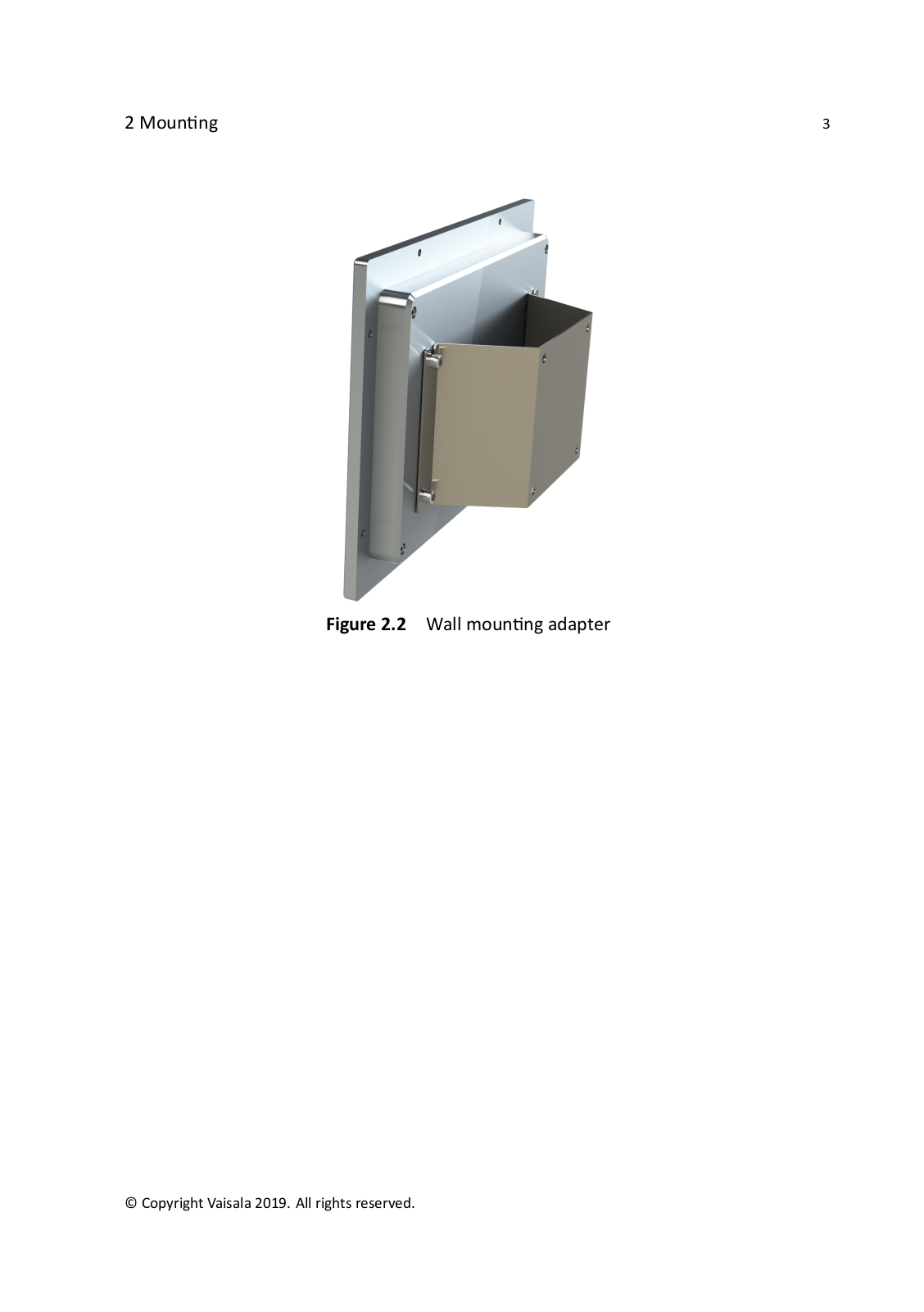
3
OMT364
3
OPT100
2
Optimus OPT100
3
P
PDT101
4
PDT102
4
PMB100
2
POWER-1
PR-23
4
PR-33
PR-33-AC
PR-43
PR-43-AC
PR-43-AP
PR-43-GC
PR-43-GP
PTB100
PTB110
3
PTB200
PTB210
7
PTB210MDSS
PTB220
3
PTB220AxB2Ax
PTB220Case
PTB220 Series
PTB220TS
2
PTB220TS / CASE
PTB330
6
PTB330TS
4
PTU200
2
PTU200MIK1
PTU200 series
PTU300
8
PTU301
PWD10
PWD12
PWD20
PWD22
2
PWD50
PWD52
Q
QMD202
QML201C
QMT103
QMT110
R
RADARS METEOROLOGIQUES
Radiosonde RS92-SGP
RD93
RD94
RDP100
Remote Divert
RFL100
4
RG13
RG13H
RM32
2
RS41
RS41-SG
RS41-SGP
2
RS92-AM
RS92-D
2
RS92-K
RS92-KL
2
RS92-SGP
6
RSA921
RSA922
RT20A
RVP900
S
SHM40
SM-3
Spectrum 4.0
SPH10
4
SPH20
3
SS-10
T
TACMET MAWS201MP
TCI101 NiteStar
TCP100
Thunderstorm LS7002
TMD62
4
TMP1
4
TMW82
TMW83
2
TMW90
TMW92
TMW93
TSS928
TWX300
V
VaiNet AP10
VERITEQ
2
VERITEQ 4000
VERITEQ SERIE 2000
Veriteq Validation/Mapping System
Veriteq viewLinc 3.6
Veriteq viewLinc 4.0
Veriteq vNet
Veriteq vNet PoE
viewlinc 3.6
4
viewLinc 4.0
viewLinc 4.1
viewLinc 4.3
vLog 4.4
Loading...
Loading...
Nothing found
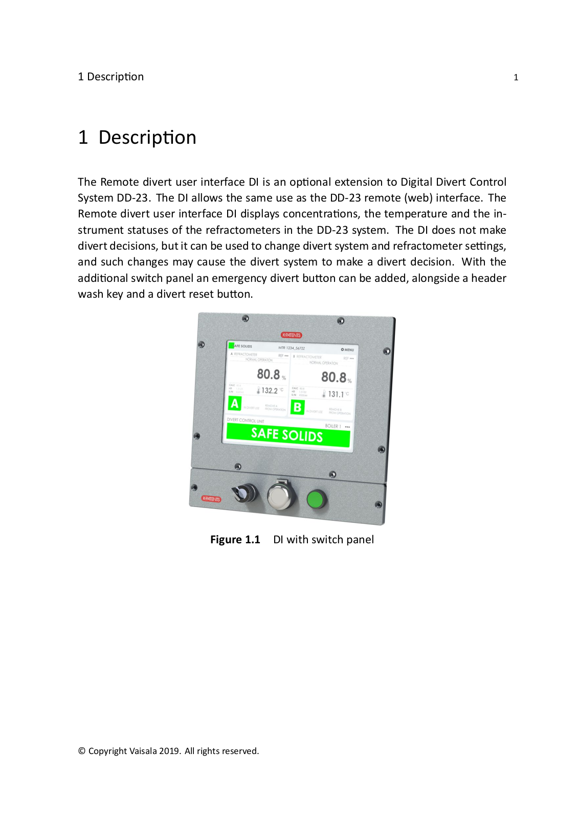
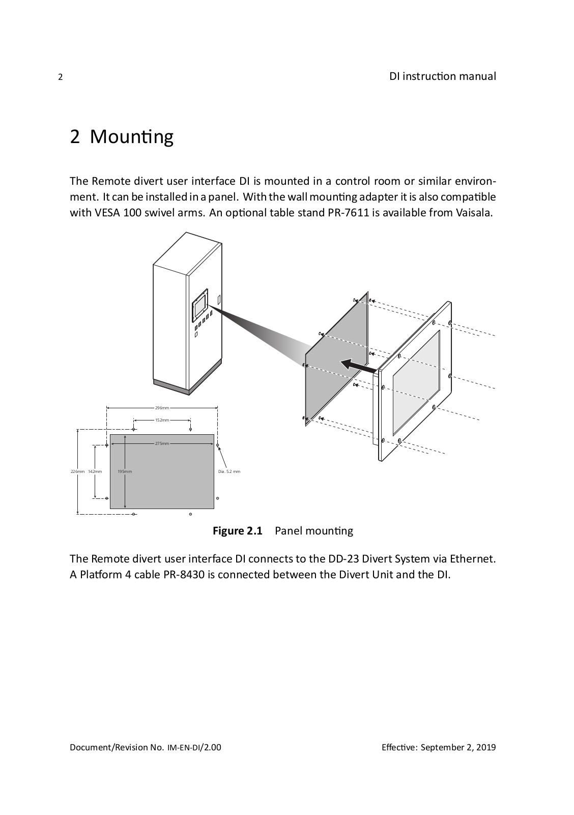
Remote Divert
Instruction Manual
32 pgs
6.54 Mb
0
Table of contents
Loading...
Vaisala Remote Divert Instruction Manual
...
Vaisala Instruction Manual
Download
Specifications and Main Features
Frequently Asked Questions
User Manual
Download
Page 1
Page 2
Page 3
Page 4
Page 5
Page 6
Page 7
Page 8
Page 9
Page 10
Page 11
Page 12
Page 13
Page 14
Page 15
Page 16
Page 17
Page 18
Page 19
Page 20
Page 21
Page 22
Page 23
Page 24
Page 25
Page 26
Page 27
Page 28
Page 29
Page 30
Page 31
Page 32
Loading...
+
hidden pages
Unhide
You need points to download manuals.
1 point = 1 manual.
You can buy points or you can get point for every manual you upload.
Buy points
Upload your manuals