

Page 1
User's Guide
Vaisala Remote Display Panel
RDP100
M211691EN-A
Page 2

PUBLISHED BY
Vaisala Oyj
Street address: Vanha Nurmijärventie 21, F I-01670 Vantaa, Finland
Mailing address: P.O. Box 26, FI-00421 Helsinki, Finland
Phone: +358 9 8949 1
Fax: +358 9 8949 2227
Visit our Internet pages at www. vaisala.com.
© Vaisala 2014
No part of t his manual may be reproduced, published or publicly displayed in any
form or by any means, electronic or mechanical (including photocopying),
normay its contents be modified, translated, adapted, sold or disclosed to a
third party without prior written permission of t he copyright holder. Translated
manuals and t ranslated portions of multilingual documents are based on the
original English versions. In ambiguous cases, the English versions are
applicable, not the translations.
The contents of this manual are subject to change wit hout prior notice.
This manual does not c reate any legally binding obligations for Vaisala towards
customers or end users. All legally binding obligations and agreements are
included exclusively in the applicable supply c ontract orthe GeneralConditions
of Sale and General Conditions of Service of Vaisala.
Page 3

RDP100 Remote Display Panel
Overview
Vaisala Remote Display Panel RDP100 is a digital display that shows the live
measurement of one or two environmental m easurement parameters, supplied
by a compatible Vaisala measurement instrument. RDP100 shows the data
from the instrument as-is - there are no adjustments or calibrations on the
display side. The parameter(s) to be displayed are select ed using D IPswitches
on the display's component board.
The housing of the RDP100 is designed t o be recessed into a wall, wit h only the
front cover visible. There is no user interface on t he outside of the RDP100.
Note: Datasheet isavailable from the product page at
www. vaisala.com/ rdp100.
Compatibility
Following Vaisala instruments are compatible with the RDP100:
l DMT132, DMT143, and DMT152 dewpoint transmitters
l DPT145 and DPT146 dewpoint and pressure transmitters
l HMDW110 series humidity and temperature transmitt ers:
l HMD110/112
l HMW110/112
l HMS110/112
l HMP60/63/110/113 series humidity and t emperature probes
l MMT162 moisture in oil and temperature transmitt er
1
Page 4

Serial Port Settings
RDP100 and t he measuring inst rument communicate on the RS-485 line using a
Vaisala proprietary protocol. There must be only one RDP100 and one
compatible inst rument on the RS-485 line - no other devices. The serial port
settings of the connected measuring instrument must be:
l 19200bits per second
l 8 data bits
l no parity bit
l one stop bit
Note: The requiredsettings are t he factory default s ettings for all of t he
compatible inst ruments. However, if you have changed the serial port
settings, y ou must change them back to 19200-8-N-1before RDP100 c an
read the instrument.
There are no requirements for the serial port operating mode (f or example,
STOPmode), address, or measurement message format of the measuring
instrument.
Power Supply and Wiring Considerations
RDP100 requires a regulated 12 ... 28 VDC supply voltage. To simplify t he
wiring and avoid ground loops, use only a single power supply to power both the
RDP100 and t he measurement instrument. The recommended wiring
arrangement depends on the instrument that is connected:
l HMDW110 series t ransmitters are designed t o supply operating
power to the RDP100. For wiring instructions, see sect ion Wiring
HMDW110 with RDP100 on page9.
l The rest of the supported instruments s houldbe powered through the
RDP100. For wiring instructions, s ee section Wiring on page8.
2
Page 5
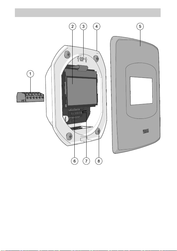
RDP100 Parts
1 = Detachable screw t erminal, max wire size 1.5 mm2(AWG16).
2 = Display element (do not touch).
3 = Direction arrow, point up duringinstallation.
4 = Electronics housing.
5 = Stainless steel front cover.
6 = DIPswitc hes f or parameter selection and unit select ion.
7 = Power pass-through jumper. Connecting t he jumper t o position 1-2 allows
the s upply voltage to pass through the RDP100 unregulated. Connecting
the jumper to position 2-3 regulates the pass-through voltage to 7.5 VDC.
8 = Mounting screws (4 pcs).
3
Page 6
Installation
Requi red tools:
l Medium size crosshead screwdriver (Pozidriv).
l Small slotted screwdriver for screw terminals and DIPswitches.
l Drilling and cutting tools as required by the wall material.
l Tools for cutting and stripping wires.
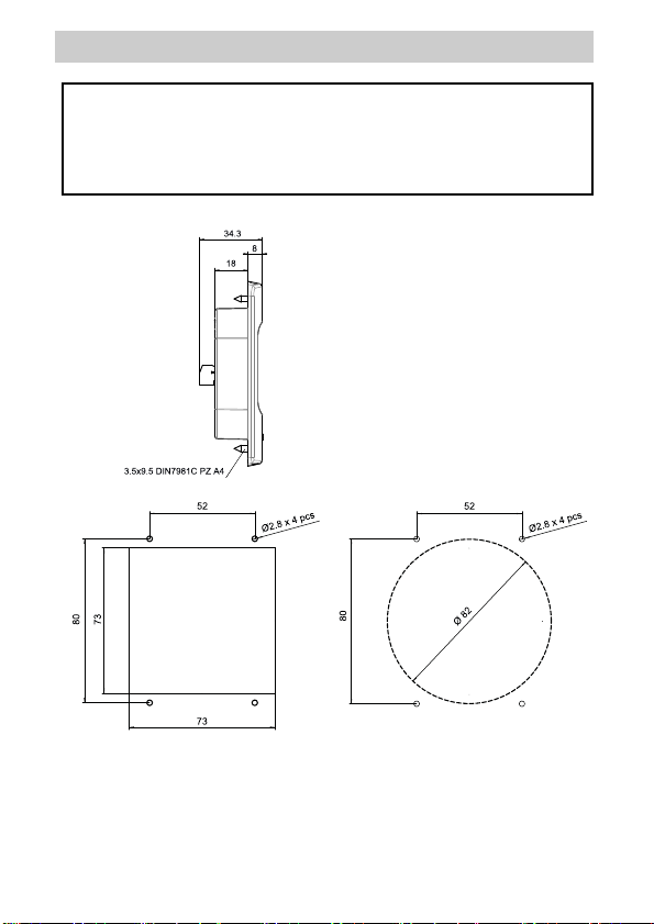
1. Prepare the mounting hole f or
attaching the housing. You can
use a Ø82 mm round hole, or a
73 mm squarehole.
2. If required by the wall material,
drill Ø2.8 mm pilot holes for the
four attachment screws.
3. Check that the housing fit s in
the installation hole, and that
there is sufficient clearance
behindthe hole.
4
Page 7
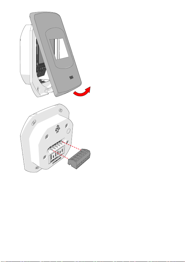
4. Remove the stainless st eel
front cover by pulling the bottom
part of t he cover away from the
housing. You can also insert a
slotted screwdriver in t he slot on
the bott om of the housing, and
lift to remove the cover.
5. Connect wiring to the
detachable screw terminal.
Refer to the terminal label on the
back of the housing, and t o the
wiring instructions in this guide:
HMDW110 series:Wiring
HMDW110 with RDP100 on
page9.
Other supported inst ruments:
Wiring on page8.
6. Depending on the instrument
you are connecting, you may
have to insert the jumper to
numberedpins that are located
to the right of the DIPswitches.
Follow t he wiring instructions.
7. When you are finished with the
wiring, plug in the screw
terminal. If supply voltage is
connected, the RDP100 will
start up at this point.
5
Page 8

8. Optional:apply sealing paste to
the back frame of the housing
(where the housing meets t he
wall when installed). Follow t he
instructions provided with the
sealing paste you are using.
9. Insert the RDP100 housing in
the mounting hole. Make sure
the housing is straight, with t he
direction arrow pointing up.
10. Attach the housing to the wall
with the screws.
11. Check the display to verify the
status. When the RDP100
starts up, it will search for a
compatible inst rument on the
RS-485 line. When found, the
display shows what instrument
is connected.
6
Page 9

12. If t he DI Pswitches on the
RDP100 are in off position (new
RDP100), t he RDP100prompts
you t o select 1-2 parameters f or
display. Use the DIPswitches
on the component board to
select the parameters. DIP 8
selects between metric and
non-metric units (f or example,
°C or ° F for temperature).
The numbers on the parameter
selection screen c orrespondto
the numbered DI Pswitches.
13. The parameter selection screen
is shown until 1-2 parameters
are chosen. The measurement
screen appears after a brief
delay when you s top changing
the DIPswitch positions.
14. Verify that the display is
showing the parameters and
units you want. You can keep
changing the DIPswitch
positions as necessary. The
parameter selection screen w ill
be shown if necessary.
15. Reattach the front cover to
complete the installation.
7
Page 10

Wiring
The wiring instruction below applies to all compatible measurement inst ruments
except the HMDW110 series (HMDW110 wiring is covered in section Wiring
HMDW110 with RDP100 on the facing page).
Use a s ingle power supply to power t he RDP100, and connect the power to the
measurement inst rument t hroughthe RD P100. Connect the power passthrough jumper on t he RDP100as indicated below.
l DMT132/152, MMT162, DPT145/146: Connect wiring t o port II .
Install the jumper on RDP100 to position 1-2.
l DMT143: Connect wiring to port marked Digital. Install t he jumper on
RDP100 to position 1-2.
l HMP60/63/110/113: C onnect t o the M8 connector. Inst all the jumper
on RDP100to position 2-3.
Caution: T he RS-485 circuit of t he compatible DMT, DPT, MMT, and
HMP transmitters is not isolated. Using the RDP100 and analog outputs
simultaneously is not supported.
Note: Connecting the jumper to position 1-2 allows the supply voltage t o
pass through the RDP100 unregulated. Connecting the jumper to position
2-3 regulates t he pass-through voltage to 7.5 VDC.
8
Page 11
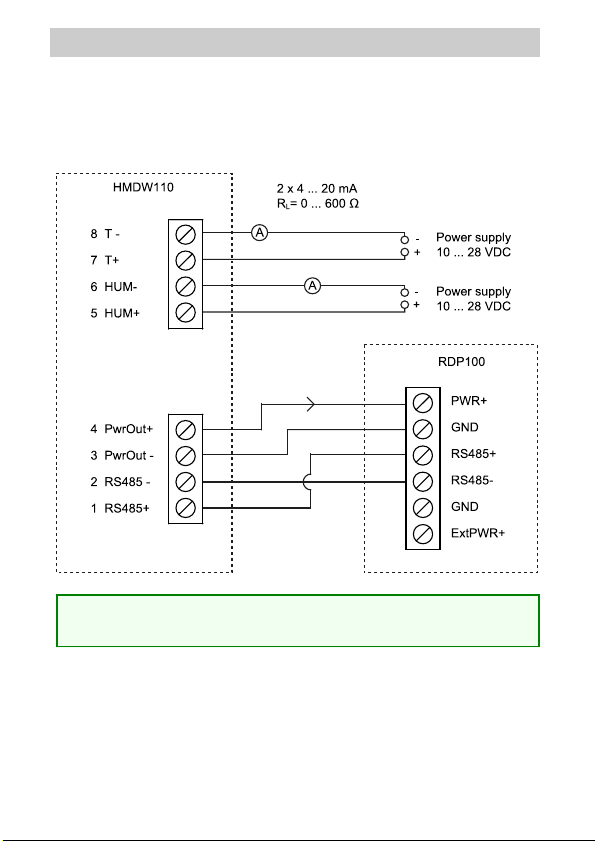
Wiring HMDW110 with RDP100
You must always connect the humidity measurement c urrent loop (HUM,
terminals 5and 6) to power the transmit ter. Connecting the t emperature
measurement current loop (terminals 7 and 8) is optional.
Connect the RDP100 Remote Display Panel using t erminals 1 .. . 4. The
HMDW110 series t ransmitter provides both power and data t o the RDP100.
Note: Whenusing the RDP100 with HMDW110 series transmitters,
remove the jumper on the R DP100 component board.
9
Page 12

HMDW110 Power Supply Requirements
HMDW110 series t ransmitters are designed f or a supply voltage range of
10... 28VDC. The minimum required voltage depends on the loop resistance
(0...600Ω) as shown below.
Troubleshooting
Probl em Possible Cause Soluti on
RDP100 does not turn
on.
Display does not find
the measurement
instrument.
Incorrect wiring. Check and correct wiring.
Wrong input voltage. Check and correct.
Display powered through
ExtPWR+ terminal but
jumper not installed.
Incorrect wiring. Check and correct wiring.
Connected inst rument not
compatible.
Connected inst rument's
serial settings are not
19200-8-N-1.
Instrument is DMT143 with
firmware version t hat is
older than 1.1.5.
Install jumper in location
1-2 or 2-3 according to
wiring instructions.
Check according t o list of
compatible inst ruments.
Check and correct.
Contact a Vaisala Service
Center f or a firmware
update.
10
Page 13

Probl em Possible Cause Soluti on
The parameter I want
is not selectable.
Parameter on screen
shows st ars "** *"
instead of
measurement reading.
Measurement unit is
not t he one Iwant.
Connected inst rument
does not provide the
desired parameter.
Measurement problem in
the c onnected instrument:
error or out of
measurement range.
Position of DIPswitch 8 on
RDP100.
Check the instrument's
documentation to verify
the parameters that are
available.
Check and correct.
Set DIP8 to metric or
non-metric as applicable.
RDP100 Maintenance
Calibration
RDP100 does not need calibration. I f the measurements on screen are not
correct, check and calibrate t he measurement instrument that is connected to
the RDP100.
Cleaning
Wipe the front cover with a soft, lint-free cloth moistened with an is opropyl
alcohol (IPA)solution or a mild detergent.
If there is dust on t he component board and the display element, open the front
cover and clean t he parts by gently blowing wit h instrument air. Avoid touching
the display element.
Spare Parts
Replacement f ront cover is available as sparepart (Vaisala order code
ASM211018SP).
11
Page 14

Download manuals f rom:
www. vaisala.com/ manuals
Technical s upport by e-mail:
helpdesk@vaisala.com
Warranty information:
www. vaisala.com/ warranty
Vaisala Service Centers:
www. vaisala.com/ servicecenters
Purchase instruments and
sparepartsonlineat: s tore.vaisala.com
*M211691EN*
c R r
 Loading...