

Page 1
QUICK REFERENCE GUIDE
Vaisala Transmitters
HMT330, DMT340, MMT330
English
Deutsch
Espanol
Suomi
Français
Nederlands
Svenska
日本語
中文
M210742EN-A
Page 2

Table of Contents
QUICK GUIDE IN ENGLISH...........................................................................3
KURZANLEITUNG AUF DEUTSCH ..............................................................7
GUÍA DE REFERENCIA RÁPIDA EN ESPANOL .......................................11
PIKAOPAS SUOMEKSI...............................................................................15
GUIDE DE DEMARRAGE RAPIDE EN FRANCAIS....................................19
SNELGIDS EN HET NEDERLANDS ..........................................................23
SNABBREFERENS PÅ SVENSKA .............................................................27
............................................................................................31
..............................................................................................35
B__________________________________________________________________ M210742EN-A
Page 3
________________________________________________________________________________
difference in temperature between the
About This Quick
environment and the probe can cause an
error of several percentages in RH.
Guide
Mounting the Probes with Cable
This Quick Guide provides an overview on
how to install Vaisala HUMICAP
Humidity and Temperature Transmitter
Series HMT330, Vaisala DRYCAP
Dewpoint and Temperature Transmitter
Series DMT340 and Vaisala HUMICAP
Moisture and Temperature Transmitter
Series for Oil MMT330. Please refer to the
relevant User's Guides for detailed
information on the use of the products.
®
®
®
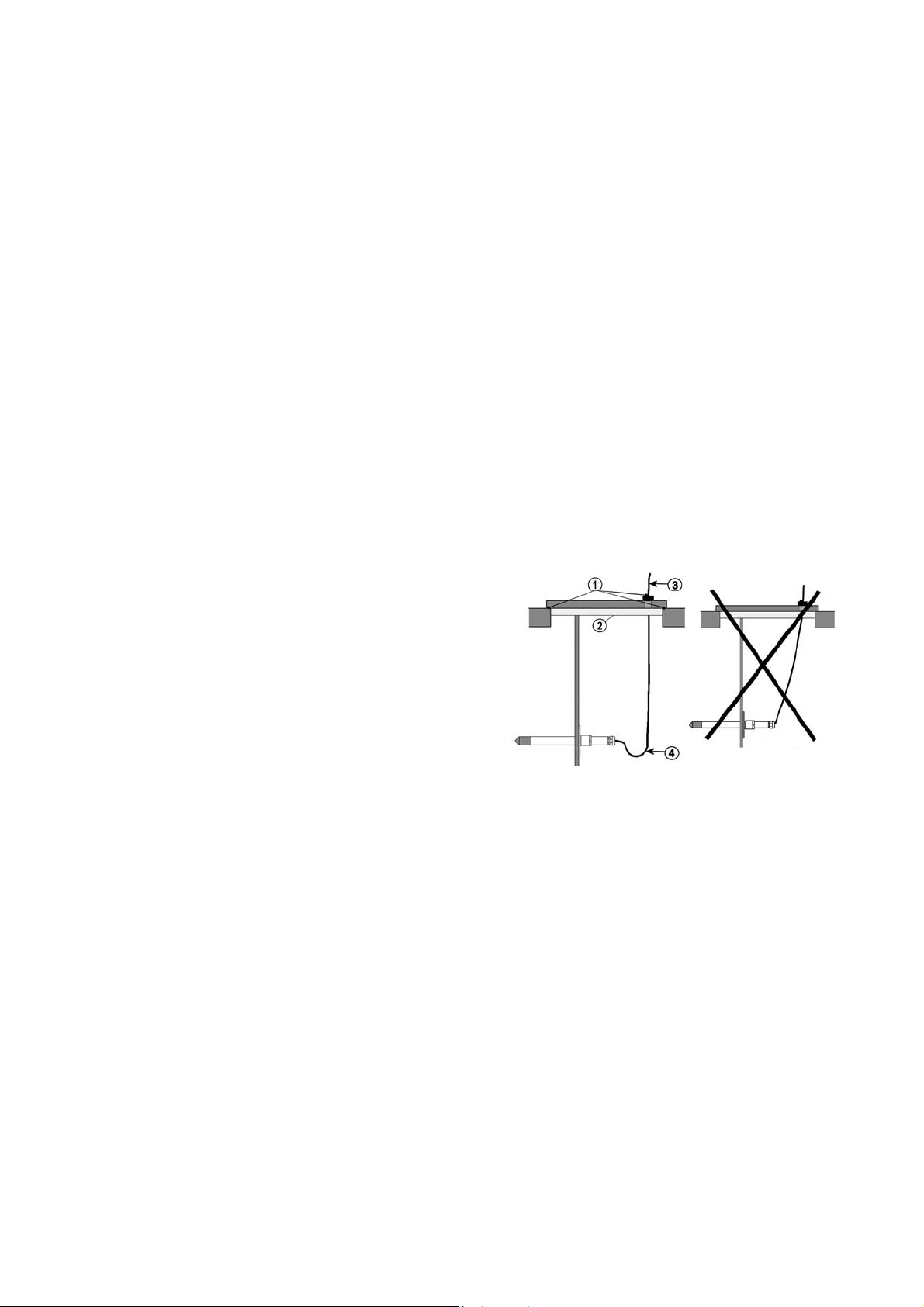
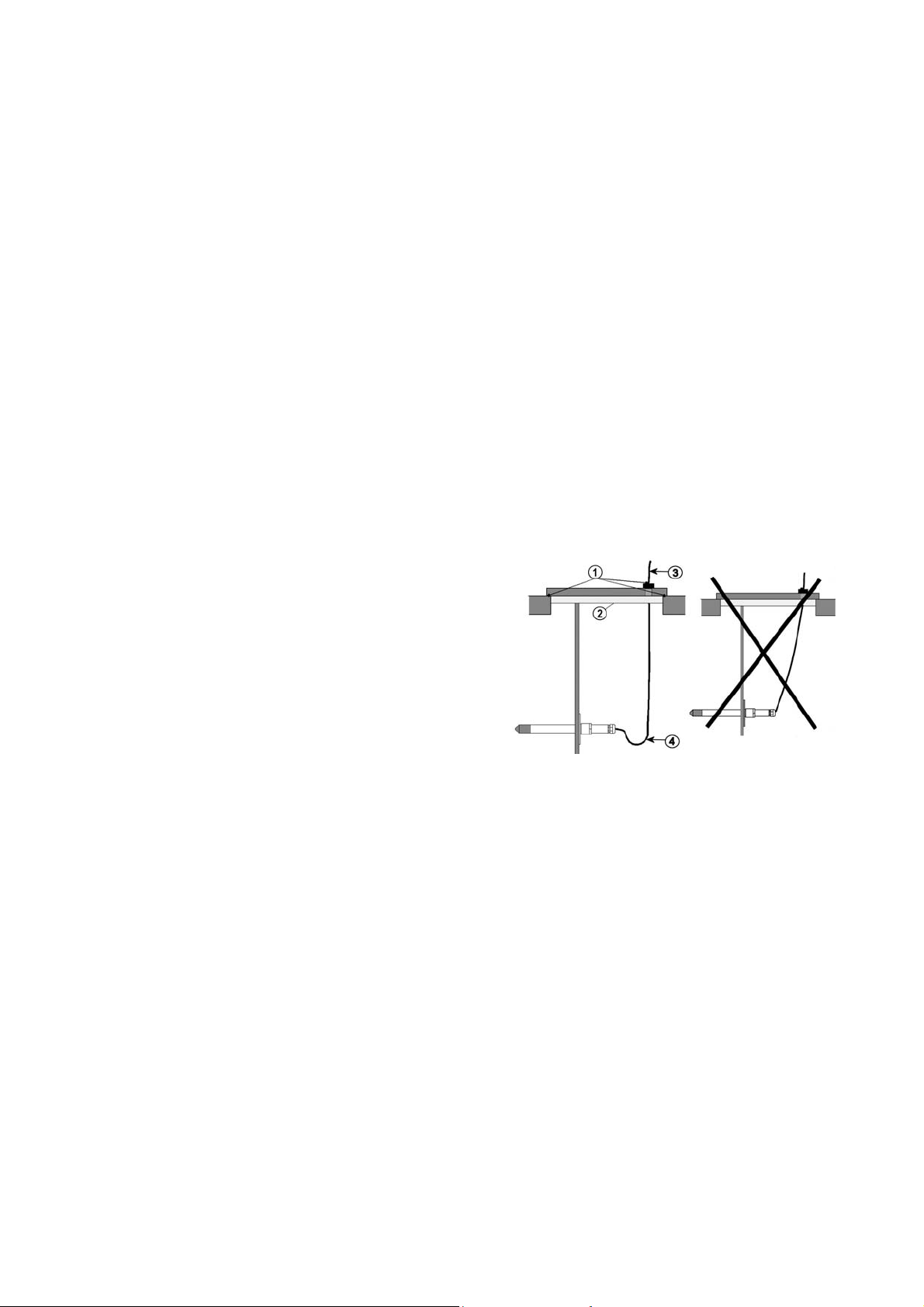
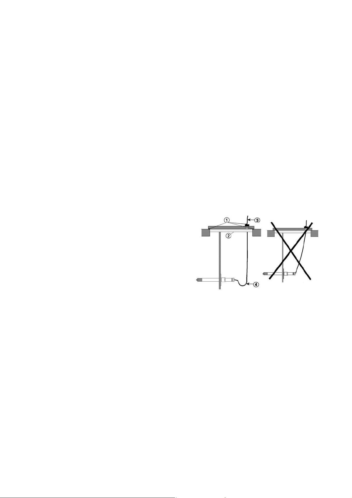
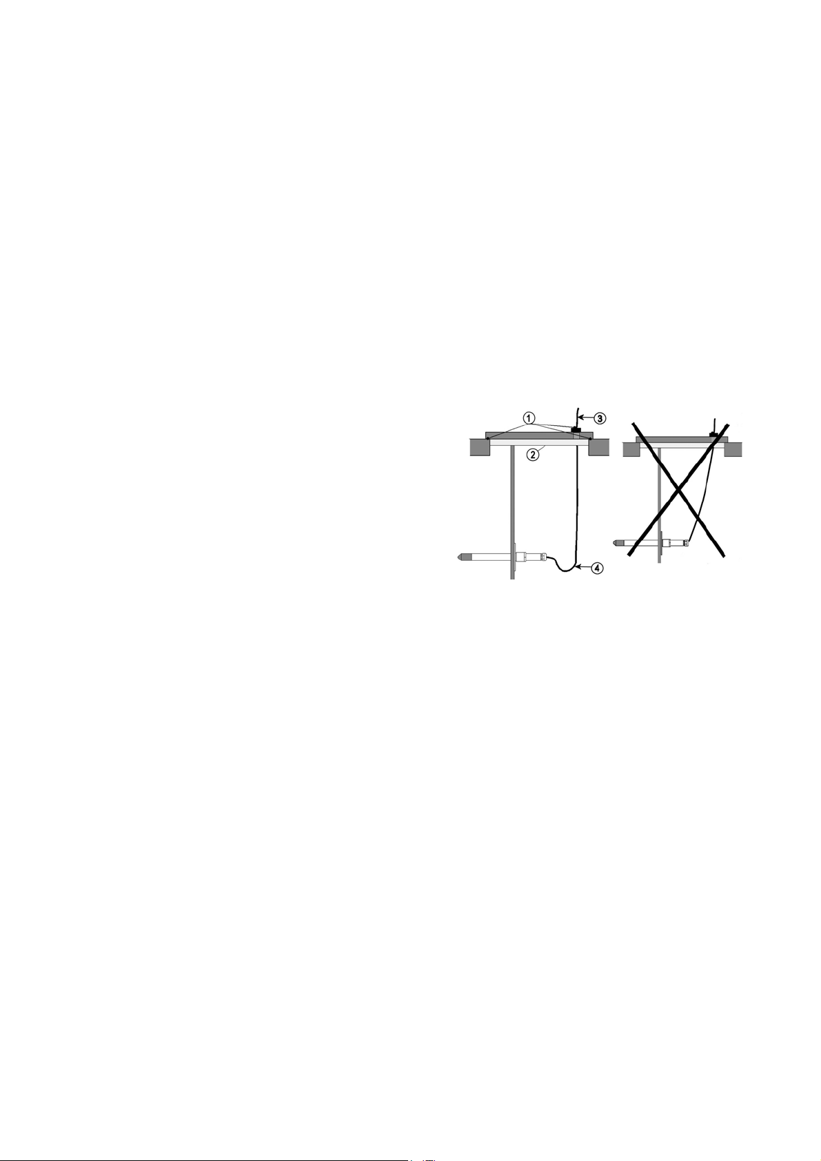
Mount the probes with a cable with the
sensor head horizontally or vertically. This
way, any water condensing on the tube
cannot flow onto the sensor.
When installing probe into a chamber with
a higher T than the surrounding the point
of entry must always be carefully
insulated. The cable must also be allowed
to hang loosely as this prevents any
condensed water from running onto the
sensor head along the cable.
Things to Consider
When Measuring Dewpoint
- If a sampling system is built instead of
direct probe installation, it is important that
the system is leak-proof. Recommended
material for sampling system construction
is stainless steel. Also PTFE may be used
down to dewpoints of -40°C / -40 °F.
- Dewpoint is a pressure dependent
parameter. It is important that the pressure
at the sensor is the true process pressure.
The temperature is not of major
importance, as long as it is above the
process dewpoint in order to avoid
condensation.
When Measuring Relative
Humidity
In humidity measurement it is essential
that the temperature of the probe and the
measured gas is the same. Even a small
0507-024
Figure 1 Horizontal Mounting of
Sensor Head
Numbers refer to Figure 1 above.
1 = To be sealed.
2 = To be insulated.
3 = Insulate the cable.
4 = Let the cable hang loosely. This
prevents condensed water running to
the sensor along the cable.
- Refer to the appropriate User's Guides for
further installation instructions for probes
with a cable as well as other installation
possibilities.
VAISALA________________________________________________________________________3
Page 4
________________________________________________________________________________
When Measuring Moisture in
Oil
- The measurement should be done in a
location that provides a representative
sample of your entire oil system (for
example, a high flow feed line or return
line to reservoir). The sensor reads that
which it is in contact with only.
- Locations to avoid include the bottom of
oil reservoirs and bends in a pipeline
where free water may settle out as well as
areas where heavy air bubbling could
occur due to turbulence caused by pumps
or agitators.
Operation
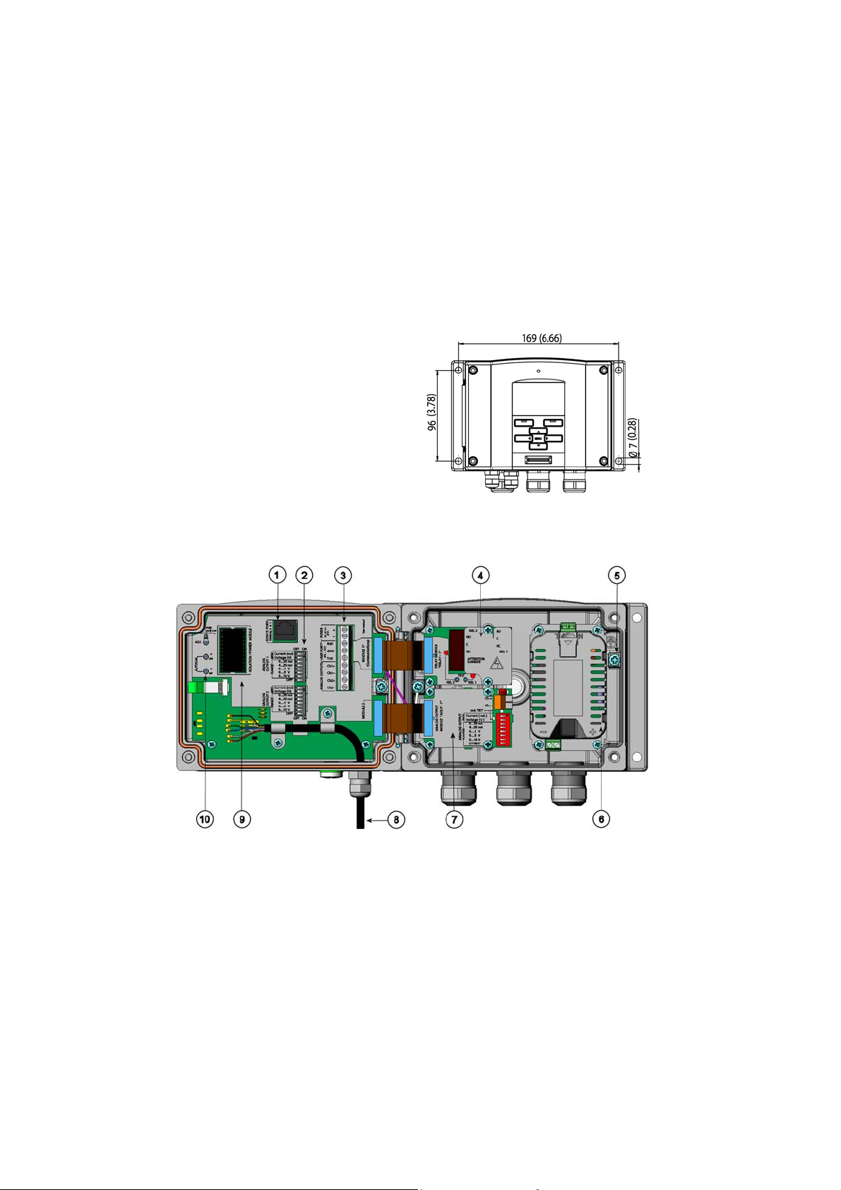
Transmitter Housing
Standard Installation
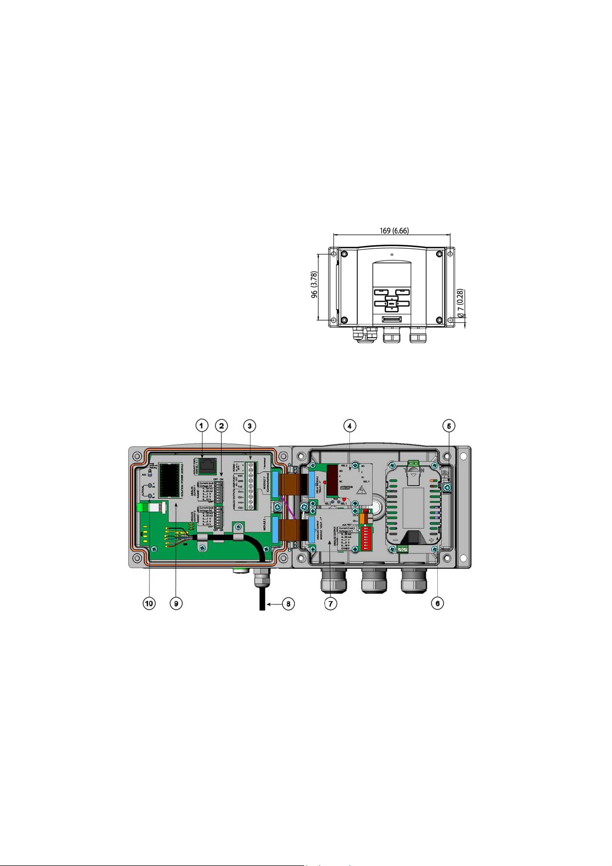
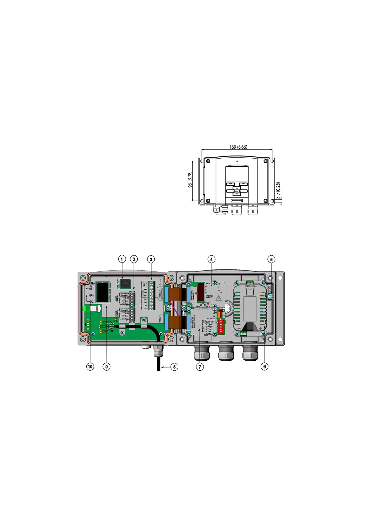
Mount the housing by fastening the
transmitter to the wall with 4 screws, for
example M6 (not provided). Refer to the
User's Guides for the use of the optional
mounting plates.
0510-026
Figure 2 Standard Mounting
Dimensions (in mm/inch)
0503-023
Figure 3 Inside of the Open Transmitter
Numbers refer to Figure 3 above.
1 = Service port (RS-232)
2 = Dip switches for analog output settings
3 = Power supply and signal wiring screw terminals
4 = Relay/RS-485 module (optional)
5 = Grounding connector
6 = Power supply module (optional)
7 = Relay module/third analog output module (optional)
8 = Probe
9 = Output isolation module/DC-DC converter (optional)
10 = Adjustment buttons with indicator led
4 ___________________________________________________________________ M210742EN-A
Page 5
________________________________________________________________________________
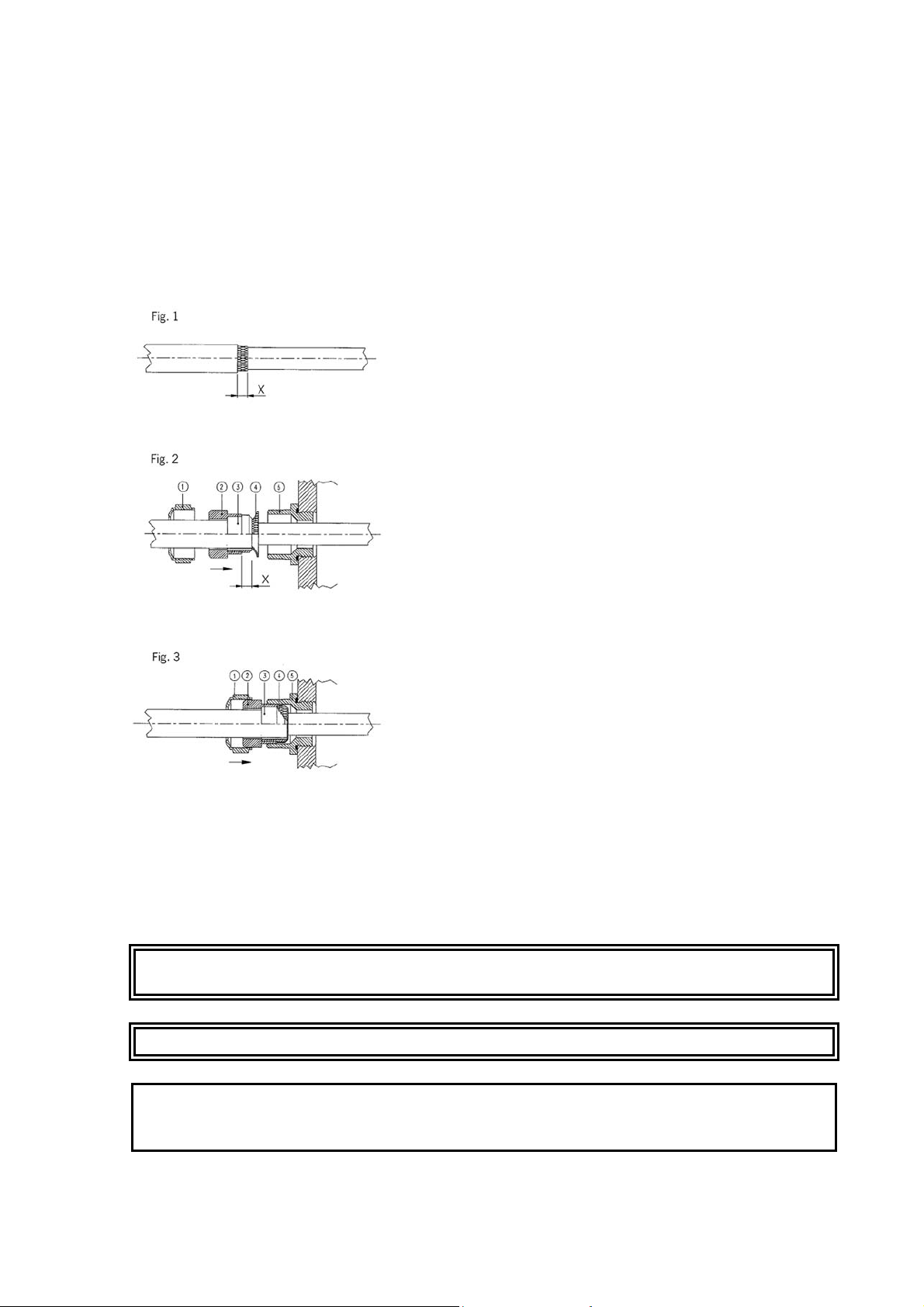
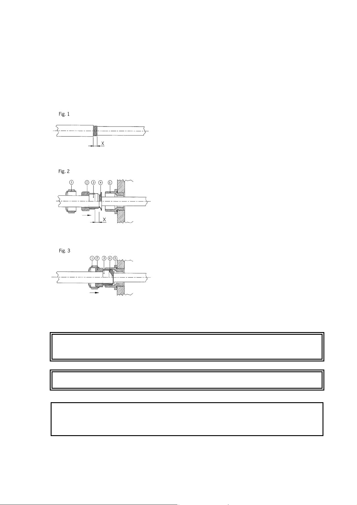
Wiring
- A single electrical cable with a screen and three to ten wires is recommended for power
and analog/serial connections. The cable diameter should be 8...11 mm. The number of
cable bushings depends on the transmitter options. Ground the screen of the electrical
cable properly to achieve the best possible EMC performance.
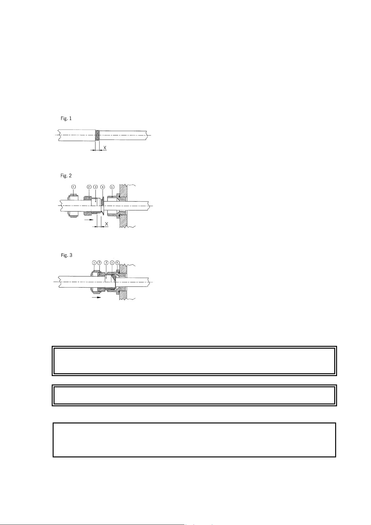
a. Cut back outer sheath to desired
length.
b. Cut back screen braiding or screen
foil to dimension X (see figure 2).
c. Push the domed cap nut (item 1) and
the seal insert with contact socket of
the gland (item 2+3) onto the cable
as shown in the diagram.
d. Bend over the screen braiding or
screen foil by about 90º (item 4).
0504-049
Figure 4 Grounding the Screen of
Electrical Cable
WARNING
WARNING
The AC (mains) power connection may be connected to the power
supply module only by an authorized electrician.
Make sure that you connect only unpowered wires.
e. Push the seal insert with the contact
socket of the gland (item 2+3) up to
the screen braiding or screen foil.
f. Mount lower part (item 5) on the
housing.
g. Push the seal with the contact socket
of the gland and (item 2+3) flush into
the lower part (item 5).
h. Screw the domed cap nut (item 1)
onto the lower part (item 5).
When connecting to a 24 VAC power
supply a separate floating supply for each
transmitter is recommended.
CAUTION
VAISALA________________________________________________________________________ 5
In case you have only one AC supply, never connect same wire to the
+ connector of a transmitter and to the - connector of another one.
This will short-circuit the transformer.
Page 6
________________________________________________________________________________
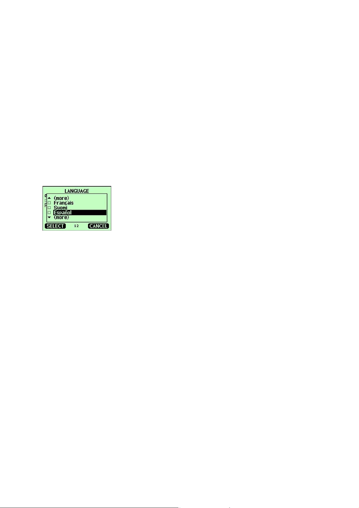
Starting Operation
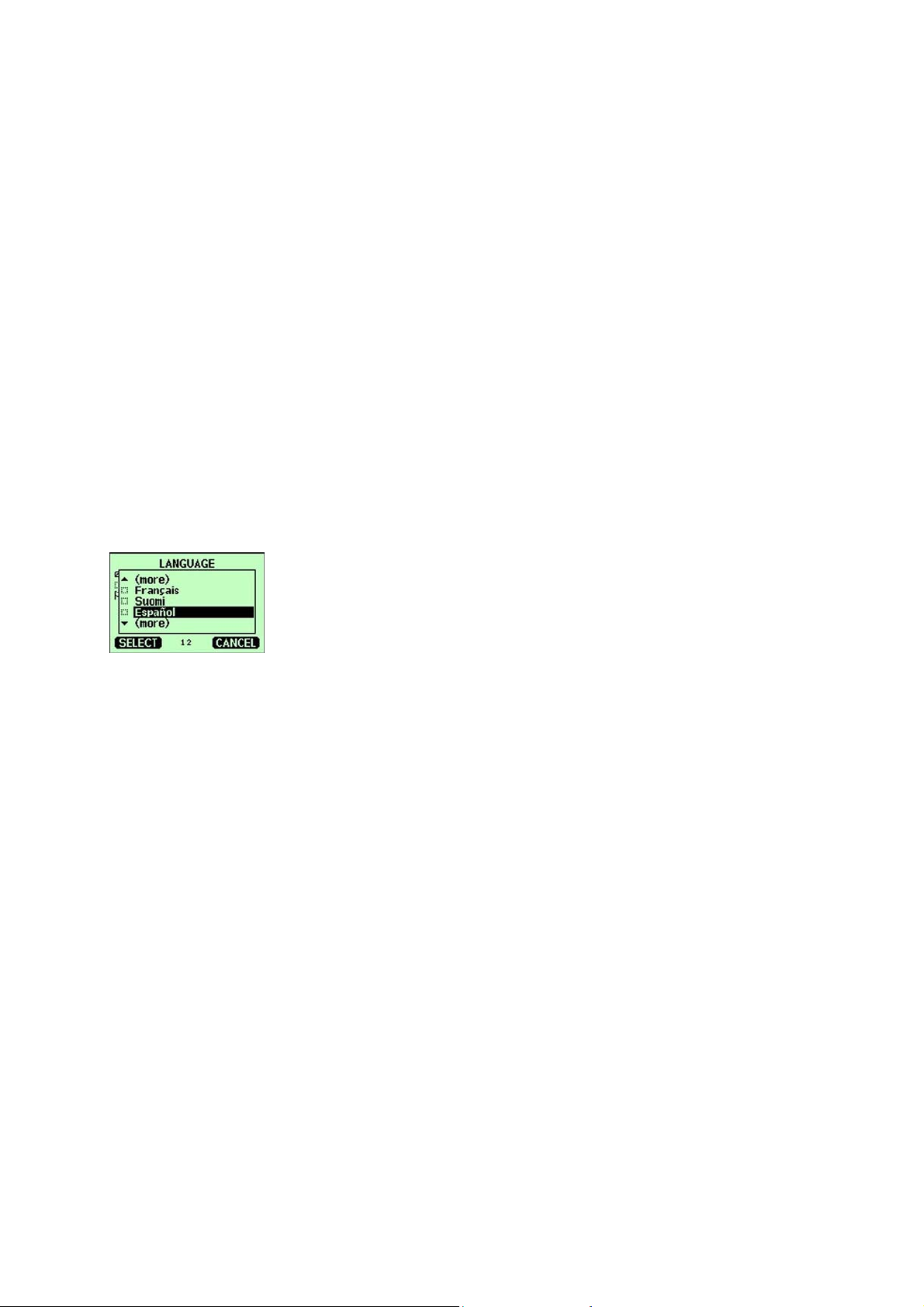
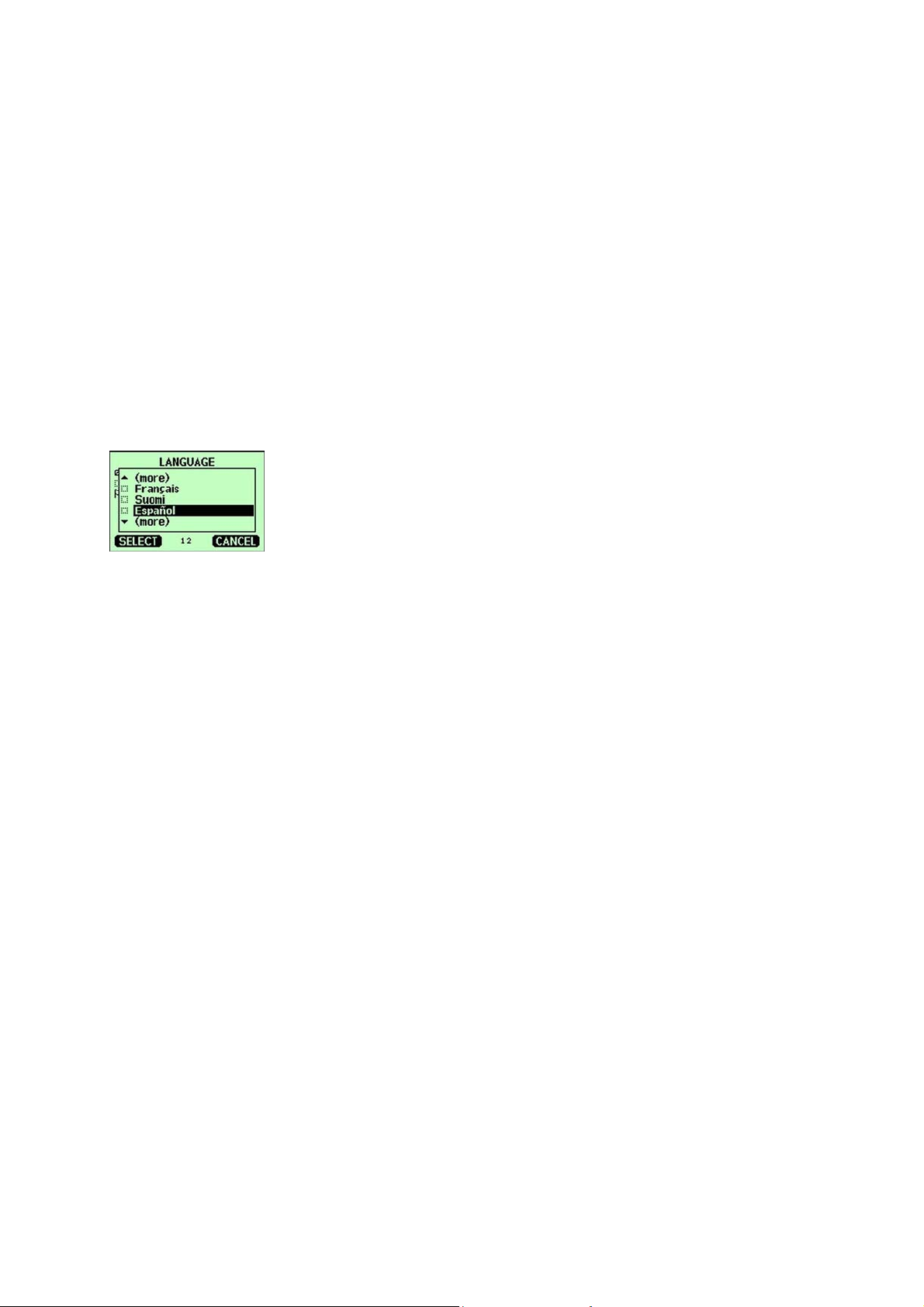
- Within a few seconds after power-up
the led on the cover of the transmitter is
lit continuously indicating normal
operation. When the transmitter
equipped with a display is turned on the
first time, the language selection
window opens.
- Select the language with arrow
buttons and press the SELECT button.
0511-114
Figure 5 Language Selection Menu
- The pressure has an effect on humidity
calculations and accuracy. Therefore,
accurate calculations can be achieved
only when the process pressure is taken
into account.
Maintenance
- The transmitter is fully calibrated and
adjusted as shipped from factory.
- Calibration must be done always when
there is a reason to believe that the
device is not within the accuracy
specifications. Calibration and
adjustment can be carried out in Vaisala
Service Centers or by the user
NORTH AMERICAN SERVICE CENTER,
phone: +1 781 933 4500
EUROPEAN SERVICE CENTER,
phone: +358 9 8949 2658
TOKYO SERVICE CENTER,
phone: +81 3 3266 9617
BEIJING SERVICE CENTER ,
phone: +86 108526 1199
www.vaisala.com
- In DMT340, the start-up time is about 6
minutes due to a self-diagnostics
procedure. During this, the outputs are
frozen.
6 ___________________________________________________________________ M210742EN-A
Page 7
________________________________________________________________________________
Über diese
Kurzanleitung
Diese Kurzanleitung vermittelt einen
Überblick über die Installation der Vaisala
HUMICAP® Feuchte- und
Temperaturmessgeber der Serie HMT330,
Vaisala DRYCAP® Taupunkt- und
Temperaturmessgeber der Serie DMT340
und Vaisala HUMICAP® Feuchte- und
Temperaturmesswertgeber für Öl der Serie
MMT330. Ausführliche Informationen
zum Einsatz der Produkte finden Sie in den
jeweiligen Bedienungsanleitungen.
Faktoren, die Sie vor
der Installation
berücksichtigen
sollten
geringe Temperaturunterschiede zwischen
der Umgebung und der Sonde können
beim Messen der relativen Feuchte (rF)
Fehler von mehreren Prozent verursachen.
Sondenmontage mit Kabel
Bei der Montage der Sonden mit Kabel
sollte der Sensorkopf horizontal oder vertikal
ausgerichtet sein. Auf diese Weise wird
verhindert, dass sich im Rohr gebildetes
Kondensat in den Sensor fließen kann.
Wenn Sie die Sonde in einer Kammer mit
einer höheren T als die umgebende
Eintrittsstelle installieren, muss stets für
eine sorgfältige Isolierung gesorgt werden.
Das Kabel muss auch lose hängen, um
einen Kondensatfluss entlang dem Kabel
auf den Sensorkopf zu verhindern.
Bei der Taupunktmessung
- Beim Aufbau eines Probennahmesystems
anstelle einer direkten Sondeninstallation
ist es wichtig, dass das System lecksicher
ist. Als Material für die Konstruktion eines
Probennahmesystems wird Edelstahl
empfohlen. Bei Taupunkten bis -40 °C / 40 °F kann darüber hinaus PTFE
verwendet werden.
- Der Taupunkt ist ein druckabhängiger
Parameter. Es ist wichtig, dass es sich
beim Druck am Sensor um den
tatsächlichen Prozessdruck handelt. Die
Temperatur ist nicht besonders wichtig,
solange sie über dem Prozesstaupunkt
bleibt, damit kein Kondensat entsteht.
Beim Messen der relativen
Feuchte
Bei der Feuchtmessung ist es entscheidend,
dass die Temperatur der Sonde und des
gemessenen Gases identisch ist. Selbst
0507-024
Abbildung 1 Horizontale Montage des
Sensorkopfes
Die Ziffern beziehen sich auf Abbildung 1 oben.
1 = Muss abgedichtet werden.
2 = Muss isoliert werden.
3 = Kabel muss isoliert werden.
4 = Lassen Sie das Kabel lose hängen.
Dies verhindert einen Kondensatfluss
entlang dem Kabel auf den Sensor.
- Weitere Installationsanweisungen für
Sonden mit Kabeln sowie weitere
Installationsmöglichkeiten finden Sie in
den entsprechenden
Bedienungsanleitungen.
VAISALA________________________________________________________________________ 7
Page 8
________________________________________________________________________________
Bei der Messung von Feuchte in Öl
- Die Messung sollte an einem Ort
durchgeführt werden, der für das gesamte
Ölsystem repräsentativ ist (z. B. eine
Ölzuleitung mit hohem Fließvermögen
oder eine Rückleitung zum Öltank). Die
Sensorwerte beziehen sich nur auf die
Umgebung, die sich im direkten Kontakt
mit dem Sensor befindet.
- Zu den Orten, die vermieden werden
sollten, gehören der Boden des Öltanks
oder Biegungen in einem Rohr, da sich
dort frei fließendes Wasser ansammeln
kann, sowie Bereiche mit einem starken
Luftblasenaufkommen aufgrund von
Turbulenzen durch Pumpen oder Rührwerke.
Betrieb
Standardinstallation des
Messgebergehäuses
Befestigen Sie das Gehäuse des
Messwertgebers mit vier Schrauben, z. B.
M6, (nicht im Lieferumfang) an der Wand.
Hinweise zum Einsatz der optionalen
Montageplatten finden Sie in den
entsprechenden Bedienungsanleitungen.
0510-026
Abbildung 2 Herkömmliche Montage
0503-023
Abbildung 3 Innenansicht des geöffneten Messwertgebers
Die Ziffern beziehen sich auf die Abbildung oben.
1 = Serviceschnittstelle (RS-232)
2 = DIP-Schalter zur Einstellung der Analogausgänge
3 = Schraubklemm e n für Stromversorgung und Signalverkabelung
4 = Relais /RS-485-Modul (optional)
5 = Erdungsanschluss
6 = Netzmodul (optional)
7 = Relaismodul/drittes analoges Ausgangsmodul (optional)
8 = Sonde
9 = Signaltrennmodul/Gleichstromwandler (optional)
10 = Einstelltasten mit LED-Anzeige
8 ___________________________________________________________________ M210742EN-A
Page 9
________________________________________________________________________________
Verkabelung
- Es genügt ein gemeinsames abgeschirmtes Kabel mit 3 bis 10 Adern für den Anschluss
der Versorgungsspannung und der Analogausgänge bzw. der seriellen Schnittstelle. Der
Kabeldurchmesser sollte 8...11 mm betragen. Die Anzahl der Verschraubungen hängt von
den Messwertgeberoptionen ab. Erden Sie die Abschirmung des Kabels sorgfältig, um ein
Höchstmaß an elektromagnetischer Verträglichkeit (EMV) zu gewährleisten.
a. Schneiden Sie die äußere
Kabelummantelung auf die
gewünschte Länge zurück.
b. Schneiden Sie das Mantelgeflecht
oder die Abschirmfolie auf das Maß
X zurück (siehe Abbildung 2).
c. Drücken Sie die gewölbte Hutmutter
(Punkt 1) und die Dichteinlage mit
der Kontaktfassung der
Verschraubung (Punkt 2+3) auf das
Kabel, wie in der Abbildung dargestellt.
d. Wölben Sie das Außenmantelgeflecht
oder die –folie um etwa 90º (Punkt 4).
e. Drücken Sie die Dichteinlage mit der
Kontaktfassung der Verschraubung
(Punkt 2+3) bis zum
Abschirmgeflecht bzw. zur –folie.
f. Montieren Sie den unteren Teil
(Punkt 5) auf das Gehäuse.
g. Drücken Sie die Dichtung mit der
0504-049
Abbildung 4 Erdung der Abschirmung
von stromführenden
Kabeln
Kontaktfassung der Verschraubung
(Punkt 2+3) bündig in den unteren
Teil (Punkt 5).
h. Schrauben Sie die gewölbte Hutmutter
(Punkt 1) auf das untere Teil (Punkt 5).
Beim Anschluss eines 24 V AC-Netzmoduls
wird für jeden Messwertgeber eine
separate Spannungsversorgung empfohlen.
WARNUNG
WARNUNG
VORSICHT
VAISALA________________________________________________________________________ 9
Der Anschluss des Netzmoduls an das Wechselstromnetz darf nur durch
einen autorisierten Fachmann erfolgen.
Vergewissern Sie sich, dass nur spannungsfreie Kabel angeschlossen werden.
Sollten Sie nur eine AC-Versorgung haben, schließen Sie niemals das
gleiche Kabel an den Pluspol eines Messwertgebers und an den Minuspol
eines anderen. Sonst kommt es zu einem Transformatorkurzschluss!
Page 10
________________________________________________________________________________
Inbetriebnahme
- Innerhalb weniger Sekunden nach dem
Einschalten leuchtet die LED auf dem
Gehäusedeckel des Messwertgebers und
signalisiert normalen Betrieb. Wenn der
Messwertgeber mit einem Display
ausgestattet ist und zum ersten Mal
eingeschaltet wird, öffnet sich das
Sprachwahlfenster:
- Wählen Sie die Sprache mit den
Pfeiltasten und drücken Sie die
SELECT Taste.
0511-114
Abbildung 5 Sprachauswahlmenü
Wartung
- Der Messwertgeber wurde werkseitig
vollständig kalibriert und justiert.
- Eine Kalibrierung muss vorgenommen
werden, wenn Grund zu der Annahme
besteht, dass die Genauigkeit des Geräts
nicht den Spezifikationen entspricht.
Die Kalibrierung und Justierung kann
vom Anwender oder vom Vaisala
Servicezentrum durchgeführt werden.
SERVICEZENTRUM NORDAMERIKA,
Telefon: +1 781 933 4500
SERVICEZENTRUM EUROPA,
Telefon: +358 9 8949 2658
SERVICEZENTRUM TOKIO,
Telefon: +81 3 3266 9617
SERVICEZENTRUM PEKING,
Telefon: +86 108526 1199
- Der Druck hat Einfluss auf die
Berechnung und Genauigkeit der
Feuchtemessung. Für besonders genaue
Messungen ist daher der Prozessdruck
am Messort zu berücksichtigen.
- Beim DMT340 dauert die Anlaufzeit
nach dem Einschalten ca. 6 Minuten
wegen einer Selbstdiagnosefunktion.
Während dieser Phase wird nichts über
die Ausgänge ausgegeben.
www.vaisala.com
10 __________________________________________________________________ M210742EN-A
Page 11
________________________________________________________________________________
Acerca de esta Guía
de referencia rápida
En esta Guía le ofrecemos información
general referente a la instalación del
Transmisor de humedad relativa y
temperatura Vaisala HUMICAP® Serie
HMT330, el Transmisor de punto de roció
y temperatura Vaisala DRYCAP® Serie
DMT340 y el Transmisor de humedad y
temperatura para aceite Vaisala
HUMICAP Serie MMT330. Consulte la
guía del usuario respectiva si desea
información más detallada acerca del uso
de cada producto.
Cosas a tener en cuenta
En la medición del punto de
roció
entorno y la sonda puede causar un error
de varias unidades del porcentaje de
humedad relativa.
Montaje de las sondas con cable
Monte las sondas que tengan un cable con
el cabezal del sensor en posición horizontal
o vertical. De esta manera, el agua que se
condense en el tubo no podrá fluir hacia el
sensor.
Cuando instale la sonda en una cámara a
una temperatura superior a la del entorno,
aísle siempre el punto de entrada con el
máximo cuidado. Además, el cable debe
colgar libremente, para evitar que sirva
para canalizar el agua condensada hacia el
cabezal del sensor.
- Si se trabaja con un sistema de muestreo
en lugar de una instalación de sondeo
directo, es importante que el sistema no
tenga fugas. El material recomendado para
la estructura de un sistema de muestreo es
acero inoxidable. También puede utilizarse
PTFE para puntos de condensación de
hasta -40°C/-40 °F.
- El punto de roció es un parámetro que
depende de la presión. Es muy importante
que el sensor esté exactamente a la misma
presión que el proceso. La temperatura es
un parámetro secundario, siempre y
cuando esté por encima del punto de roció
del proceso, para evitar la condensación.
En las mediciones de humedad
relativa
Para medir correctamente la humedad
relativa, la sonda y el gas medido deben
estar a la misma temperatura. La más
mínima diferencia de temperatura entre el
0507-024
Figura 1 Montaje horizontal del
cabezal del sensor
Los números hacen referencia a la figura
1 superior.
1 = Sellar.
2=Aislar.
3 = Aislar el cable.
4 = Dejar que el cable cuelgue libremente.
De esta forma, se impide que el agua
condensada fluya hacia el sensor.
- Puede consultar en las guías del usuario
respectivas otras instrucciones de
instalación de las sondas con cable, así
como otras posibilidades de instalación.
VAISALA_______________________________________________________________________ 11
Page 12
________________________________________________________________________________
En la medición de la humedad
del aceite
- La medición debe realizarse en un lugar
en el que se encuentre una muestra
representativa del sistema de lubricación
completo (por ejemplo, un tubo de
alimentación de alto caudal o una tubería
de retorno al depósito). El sensor
únicamente detecta los parámetros del
aceite con el que está en contacto.
- Lugares que deben evitarse: el fondo de
los depósitos de aceite y los codos de
tuberías, donde puede haberse acumulado
agua, así como zonas donde puedan
originarse burbujas de agua a causa de las
turbulencias que producen las bombas y
los agitadores.
Instalación normal
del alojamiento del
transmisor
Para montar el alojamiento, sujete el
transmisor a la pared con 4 tornillos, por
ejemplo, M6 (no incluidos). En las guías
del usuario se explica el uso de placas de
montaje opcionales.
0510-026
Figura 2 Montaje normal
Funcionamiento
Figura 3 Interior del transmisor abierto
Los números hacen referencia a la figura superior.
1 = Puerto de mantenimiento ( R S-232)
2 = Conmutadores de selección para configurar la salida analógica
3 = Terminales roscados para la fuente de alimentación y los cables de señal
4 = Módulo de relé/RS-485 (opcional)
5 = Conector de puesta a tierra
6 = Módulo de fuente de alimentación (opcional)
7 = Módulo de relé/Módulo de tercer a salida analógica (opcional)
8 = Sonda
9 = Módulo de aislamiento de salida/Convertidor CC-CC (opcional)
10 = Botones de ajuste con LED indicador
0503-023
__________________________________________________________________ M210742EN-A
Page 13

________________________________________________________________________________
Cableado
- Para las conexiones de alimentación y analógicas/serie se recomienda un cable eléctrico
único, provisto de apantallamiento y entre tres y diez hilos. El cable debe tener un
diámetro entre 8 y 11 mm. El número de casquillos de cable depende de las opciones del
transmisor. Se necesita una masa correcta para el apantallamiento del cable eléctrico, a fin
de obtener una compatibilidad electromagnética óptima.
a. Recorte la funda exterior con la longitud
deseada.
b. Recorte el trenzado o la lámina del
apantallamiento conforme a la
dimensión X (consulte la figura 2).
c. Apriete el tapón roscado con forma de
cúpula (elemento 1) y la pieza de
sellado con el manguito de contacto del
casquillo (elemento 2+3) sobre el cable,
como se muestra en el diagrama.
d. Doble el trenzado o la lámina del
apantallamiento aproximadamente 90º
(elemento 4).
e. Empuje hacia arriba la pieza de sellado
con el manguito de contacto del
casquillo (elemento 2+3), hacia el
trenzado o la lámina del
apantallamiento.
f. Monte la pieza inferior (elemento 5) en
el alojamiento.
g. Empuje la pieza de sellado con el
manguito de contacto del casquillo
(elemento 2+3) hasta que esté al mismo
nivel que la pieza inferior (elemento 5).
h. Enrosque el tapón roscado con forma de
0504-049
Figura 4 Puesta a masa del
apantallamiento del cable
eléctrico
cúpula (elemento 1) sobre la pieza
inferior (elemento 5).
Para conectar una fuente de alimentación
de 24 V CA, se recomienda utilizar una
alimentación flotante para cada transmisor.
ADVERTENCIA
ADVERTENCIA
PRECAUCIÓN
VAISALA_______________________________________________________________________ 13
Únicamente un electricista autorizado debe realizar la conexión
de corriente alterna (red) al módulo de fuente de alimentación.
Al realizar las conexiones, desconecte la alimentación de los cables.
Si sólo dispone de un suministro de CA, no conecte el mismo
cable al conector + de un transmisor y al - de otro, ya que
produciría un cortocircuito en el transformador.
Page 14
________________________________________________________________________________
Puesta en servicio
- A los pocos segundos del encendido, el
LED de la cubierta del transmisor se
enciende sin interrupción para indicar
un funcionamiento normal. La primera
vez que se enciende el transmisor
equipado con pantalla, se abre la
ventana de selección de idioma.
- Seleccione el idioma con los botones de
flecha y pulse el botón SELECT.
0511-114
Figura 5 Menú de selección de idioma
- El valor de la presión influye en el
cálculo de la humedad relativa y en su
precisión. En consecuencia, para
obtener un cálculo preciso debe
incorporarse la presión del proceso.
Mantenimiento
- El transmisor se suministra de fábrica
completamente calibrado y ajustado.
- Calibre el dispositivo si tiene alguna
razón para creer que las medidas no son
exactas. El procedimiento de
calibración y ajuste puede ser realizado
por un centro de servicio técnico de
Vaisala o por el usuario.
CENTRO DE SERVICIO TÉCNICO EN
NORTEAMÉRICA,
Teléfono: +1 781 933 4500
CENTRO DE SERVICIO TÉCNICO EN
EUROPA,
Teléfono: +358 9 8949 2658
CENTRO DE SERVICIO TÉCNICO EN
TOKIO,
Teléfono: +81 3 3266 9617
CENTRO DE SERVICIO TÉCNICO EN
PEKÍN,
Teléfono: +86 108526 1199
- En el DMT340, el tiempo de inicio es
de aproximadamente 6 minutos, a causa
del proceso de autodiagnóstico. Durante
este tiempo, no se muestran mediciones.
www.vaisala.com
14 __________________________________________________________________ M210742EN-A
Page 15

________________________________________________________________________________
Kaapelilla varustettujen mittapäiden
Tietoja pikaoppaasta
Tämä pikaopas on yleiskuvaus Vaisala
HUMICAP® kosteus- ja
lämpötilalähetinsarjan HMT330, Vaisala
DRYCAP® kastepiste- ja
lämpötilalähetinsarjan DMT340 ja Vaisala
HUMICAP® öljynkosteus- ja
lämpötilalähetinsarjan MMT330
asentamisesta. Tarkemmat tiedot tuotteiden
käytöstä ovat tuotteiden käyttöoppaissa.
asentaminen
Asenna kaapelilla varustetut mittapäät
siten, että mittapää on vaaka- tai
pystysuorassa. Näin putkeen mahdollisesti
tiivistyvä vesi ei pääse valumaan anturiin.
Jos mittapää asennetaan kammioon, jonka
lämpötila on ympäristön lämpötilaa
korkeampi, läpimenokohta on aina
eristettävä huolellisesti. Kaapelin täytyy
antaa roikkua vapaasti, koska silloin
mahdollinen tiivistynyt kosteus ei pääse
valumaan kaapelia pitkin mittapäähän.
Huomioon otettavaa
Kastepisteen mittaaminen
- Jos mittapään suoraan asentamisen
asemesta on rakennettu
näytteenottojärjestelmä, järjestelmän
täytyy olla vuotamaton.
Näytteenottojärjestelmän rakentamiseen
kannattaa käyttää ruostumatonta terästä.
Myös PTFE:tä voi käyttää, jos kastepiste
on enintään –40°C.
- Kastepiste on paineesta riippuvainen
ominaisuus. Mittapään ympärillä olevan
paineen täytyy olla sama kuin prosessin
todellisen paineen. Lämpötilalla ei ole
kovin suurta merkitystä, kunhan se on
korkeampi kuin prosessin kastepiste.
Muuten voi tapahtua kosteuden
tiivistymistä.
Suhteellisen kosteuden
mittaaminen
Kosteutta mitattaessa on erittäin tärkeää,
että mittapään ja mitattavan kaasun
lämpötila on sama. Jo pieni ero ympäristön
ja anturin lämpötiloissa voi aiheuttaa
suhteellisen kosteuden arvoon usean
prosentin virheen.
0507-024
Kuva 1 Mittapään asentaminen
vaakasuoraan
Numerot viittaavat edellä olevaan kuvaan 1.
1 = Tiivistettävä.
2 = Eristettävä.
3 = Kaapeli on eristettävä.
4 = Anna kaapelin roikkua vapaasti.
Tämä estää tiivistynyttä kosteutta
valumasta anturiin kaapelia pitkin.
- Lisää ohjeita kaapelilla varustettujen
mittapäiden asentamisesta ja muista
asennusmahdollisuuksista on tuotteiden
käyttöoppaissa.
VAISALA_______________________________________________________________________ 15
Page 16

________________________________________________________________________________
Öljynkosteuden mittaaminen
- Mittaus tulisi tehdä kohdasta, josta
saadaan edustava näyte koko
öljyjärjestelmästä (esimerkiksi syöttöputki,
jossa on suuri virtaus, tai säiliöön menevä
paluuputki). Mittapää lukee vain sen
kohdan tiedot, johon se on kosketuksessa.
- Vältettäviä kohtia ovat öljysäiliöiden
pohjat ja putkistojen mutkat, joihin voi
kertyä vettä, sekä alueet, joilla ilma voi
kuplia voimakkaasti pumppujen tai
sekoittimien aiheuttaman liikkeen vuoksi.
Käyttö
Lähettimen
vakioasennus
Kiinnitä lähetin seinään neljällä ruuvilla
(esimerkiksi M6, eivät sisälly
toimitukseen). Käyttöoppaissa on tietoja
lisävarusteena saatavien asennuslevyjen
käytöstä.
0510-026
Kuva 2 Vakioasennus
0503-023
Kuva 3 Lähetin avattuna
Numerot viittaavat edellä olevaan kuvaan.
1 = Huoltoportti (RS-232)
2 = Analogisen lähdön asetusten DIP-kytkimet
3 = Tehonsyöttö ja signaalijohtojen ruuviliitännät
4 = Rele-/RS-485-moduuli ( valinnainen)
5 = Maadoitusliitin
6 = Tehonsyöttömoduuli (valinnainen)
7 = Relemoduuli / kolmas analoginen ulostulomoduuli (lisävaruste)
8 = Mittapää
9 = Lähtöeristysmoduuli/DC-DC-muuntaja (lisävaruste)
10 = Merkkivalolliset säätöpainikkeet
16 __________________________________________________________________ M210742EN-A
Page 17

________________________________________________________________________________
Johdotus
- Virransyötön ja analogisten kytkentöjen / sarjakytkennän tekemiseen suositellaan yhtä
suojattua sähkökaapelia, jossa on 3–10 johdinta. Kaapelin halkaisijan tulisi olla 8–11 mm.
Kaapelien läpivientiholkkien määrä vaihtelee lähetinmallin mukaan. Sähkökaapelin suojus
on maadoitettava asianmukaisesti parhaan mahdollisen EMC-suojauksen saamiseksi.
a. Leikkaa ulkokuori halutun pituiseksi.
b. Leikkaa suojapunonta tai suojafolio
mittaan X (katso kuva 2).
c. Työnnä kaapeliin kupumutteri
(kohta 1) ja tiiviste sekä
tiivistysholkin hylsy (kohdat 2+3)
kuvassa esitetyllä tavalla.
d. Taivuta suojapunontaa tai
suojafoliota noin 90º (kohta 4).
e. Työnnä tiiviste sekä tiivistysholkin
hylsy (kohdat 2+3) suojapunontaan
tai suojafolioon saakka.
0504-049
Kuva 4 Sähkökaapelin suojan
maadoittaminen
VAARA
VAARA
Vaihtovirtaliitännän saa kytkeä tehonsyöttömoduuliin ainoastaan
valtuutettu sähköasentaja.
Varmista, että kytket vain jännitteettömiä johtimia.
f. Kiinnitä alaosa (kohta 5) koteloon.
g. Työnnä tiiviste ja tiivistysholkin
hylsy (kohdat 2+3) suoraan alaosaan
(kohta 5).
h. Ruuvaa kupumutteri (kohta 1) kiinni
alaosaan (kohta 5).
Kytkettäessä 24 V AC:n virtalähteeseen,
suositellaan jokaiselle lähettimelle
käytettäväksi erillistä kelluvaa
tehonsyöttöä.
VAROITUS
VAISALA_______________________________________________________________________ 17
Jos käytettävissä on vain yksi AC-tehonsyöttö, samaa johdinta ei saa
koskaan kytkeä yhden lähettimen +-liittimeen ja toisen lähettimen –liittimeen. Muuten lähetin menee oikosulkuun.
Page 18

________________________________________________________________________________
Huolto
Käytön aloittaminen
- Lähetin on kalibroitu ja viritetty täysin
- Lähettimen kannen merkkivalo syttyy
pysyvästi muutaman sekunnin kuluttua
virran kytkemisestä. Se ilmaisee
normaalin toiminnan. Jos lähettimessä
on valinnainen näyttö ja lähetin
kytketään päälle ensimmäisen kerran,
näyttöön tulee kielen valintavalikko.
- Valitse kieli nuolipainikkeilla ja
paina SELECT-painiketta.
0511-114
Kuva 5 Kielenvalintavalikko
valmiiksi tehtaalla.
- Kalibrointi on tehtävä aina, kun on
syytä epäillä, ettei laite vastaa
tarkkuusspeksejä. Kalibroinnin ja
virityksen voi teettää Vaisalan
huoltopalvelussa. käyttäjä voi tehdä ne
myös itse.
POHJOIS-AMERIKAN HUOLTOKESKUS,
puhelin: +1 781 933 4500
EUROOPAN HUOLTOKESKUS,
puhelin: +358 9 8949 2658
TOKION HUOLTOKESKUS,
puhelin: +81 3 3266 9617
BEIJINGIN HUOLTOKESKUS,
puhelin: +86 108526 1199
- Paine vaikuttaa kosteuslaskelmiin ja
niiden tarkkuuteen. Täsmällisiä
laskelmia voidaan tehdä ainoastaan
ottamalla huomioon myös prosessin
paine.
- DMT340:n käynnistyminen kestää noin
6 minuuttia, koska anturi suorittaa ensin
itsediagnoosin. Sen aikana lähetin ei
lähetä tietoja.
www.vaisala.com
18 __________________________________________________________________ M210742EN-A
Page 19

________________________________________________________________________________
À propos de ce guide
de démarrage rapide
Ce Guide de démarrage rapide présente la
manière dont installer le transmetteur
d’humidité et de température Vaisala
HUMICAP® de la série HMT330, le
transmetteur de point de rosée et de
température Vaisala DRYCAP® de la série
DMT340 ainsi que le transmetteur
d’humidité et de température pour huile de
la série MMT330. Veuillez consulter le
Guide de l'utilisateur approprié pour plus
de détails sur l'utilisation des produits.
Éléments à prendre
en compte
température entre l'environnement et la
sonde peut engendrer une erreur de
plusieurs pourcents dans la mesure de
l’HR.
Montage des sondes avec câble
Lors du montage des sondes avec câble, la
tête du capteur doit être placée
horizontalement ou verticalement. De
cette façon, l’eau se condensant sur le tube
ne peut pas glisser sur le capteur.
Lors de l’installation d’une sonde dans une
chambre dont la température est supérieure
à l’environnement, le point d’entrée doit
toujours être soigneusement isolé. Le
câble doit également pendre sans être
tendu, car cela empêchera toute
condensation d'eau de couler dans la tête
du capteur le long du câble.
Lors de la mesure du point de
rosée
- Si vous avez construit un système
d’échantillonnage au lieu d’installer
directement les sondes, le système doit être
étanche. Nous conseillons d’utiliser de
l’acier inoxydable pour construire ce
système d'échantillonnage. Il faut
également utiliser du PTFE vers les points
de rosée de – 40 °C / - 40 °F.
- Le point de rosée est un paramètre
dépendant de la pression. Il est important
que la pression au niveau du capteur soit la
pression réelle du process. La température
n’est pas si importante tant qu’elle se situe
au-dessus du point de rosée du process afin
d’éviter toute condensation.
Lors de la mesure de
l’humidité relative
Lors de la mesure de l’humidité, il est
essentiel que la température de la sonde et
celle du gaz mesuré soient identiques.
Même une légère différence de
0507-024
Figure 1 Montage horizontal de la
tête du capteur
Les numéros font référence à la Figure 1 ci-dessus.
1 = A étanchéifier.
2 = A isoler.
3 = Isolez le câble.
4 = Laissez pendre le câble sans le tendre.
Cela empêchera l'eau condensée de
couler sur le capteur le long du câble.
- Consultez le Guide de l’utilisateur
approprié pour de plus amples instructions
d'installation de sondes avec câble ainsi
que pour d’autres possibilités
d’installation.
VAISALA_______________________________________________________________________ 19
Page 20

________________________________________________________________________________
Lors de la mesure de
l’humidité dans l’huile
- La mesure doit s’effectuer dans un
endroit représentatif du circuit de l'huile
(par exemple, une conduite d’alimentation
à haut débit ou une canalisation de retour
vers le réservoir). Le capteur détecte
uniquement les paramètres de l’huile avec
laquelle il est en contact.
- Les emplacements à éviter sont les
suivants : le fond des réservoirs à huile et
des coudes dans une conduite, où de l’eau
libre peut se déposer ainsi que les zones où
peuvent se créer d’importantes bulles d’air
à cause des turbulences provoquées par les
pompes et les agitateurs.
Utilisation
Installation standard du
boîtier du transmetteur
Montez le boîtier en fixant le transmetteur
sur le mur à l'aide de 4 vis, par exemple,
des M6 (non fournies). Consultez les
Guides de l’utilisateur concernant
l’utilisation des plaques de montage en
option.
0510-026
Figure 2 Montage standard
0503-023
Figure 3 Vue intérieure du transmetteur ouvert
Les numéros font référence à la Figure ci-dessus.
1 = Port de service (RS-232)
2 = Commutateurs DIP pour le paramétrage des sorties analogiques
3 = Bornes à vis pour le câblage de l'alimentation et des signaux
4 = Module relais/RS-485 (en option)
5 = Connecteur à la terre
6 = Module d'alimentation (en option)
7 = Module relais/troisième module de sortie analogique (en option)
8 = Sonde
9 = Module d’isolation de la sortie/convertisseur c.c.-c.c. (en option)
10 = Boutons de réglage avec voyant DEL
20 __________________________________________________________________ M210742EN-A
Page 21

________________________________________________________________________________
Câblage
- Pour les connexions à l'alimentation et les connexions analogiques/série, nous vous
conseillons d'utiliser un seul câble électrique blindé de trois à dix fils. Le diamètre du
câble doit être compris entre 8 et 11 mm. Le nombre de presse-étoupes dépend des options
du transmetteur. Mettez correctement à la terre le blindage du câble électrique afin
d'obtenir les meilleures performances CEM possibles.
a. Coupez la gaine extérieure à la longueur
voulue.
b. Coupez la tresse ou la feuille du
blindage à la dimension X (voir
figure 2).
c. Poussez l'écrou à calotte (élément 1)
ainsi que l'écrou en plomb avec la
douille de contact du fouloir (élément
2+3) dans le câble, comme illustré sur
le schéma.
d. Pliez la tresse ou la feuille du blindage à
environ 90 ° (élément 4).
e. Poussez l'écrou en plomb avec la
douille de contact du fouloir (élément
2+3) jusqu'à la tresse ou la feuille.
f. Fixez la partie inférieure (élément 5) sur
le boîtier.
g. Poussez l'écrou en plomb (élément 2+3)
et enfoncez-le dans la partie inférieure
(élément 5).
0504-049
Figure 4 Mise à la terre du blindage
d’un câble électrique
h. Vissez l'écrou à calotte (élément 1) sur
la partie inférieure (élément 5).
Lors de la connexion à une alimentation
24 Vc.a., nous vous conseillons d’utiliser
une alimentation flottante séparée pour
chaque transmetteur.
AVERTISSEMENT
AVERTISSEMENT
ATTENTION
VAISALA_______________________________________________________________________ 21
La connexion d'alimentation c.a. du réseau électrique ne peut
être connectée au module d'alimentation que par un électricien
agréé.
Veillez à ne connecter que les câbles non alimentés.
Si vous ne disposez que d'une alimentation c.a., ne connectez
jamais le même câble au connecteur + d'un transmetteur et au
connecteur - d'un autre. Cela pourrait court-circuiter le
transformateur.
Page 22

________________________________________________________________________________
Démarrage
- Quelques secondes après la mise sous
tension, la DEL du capot du
transmetteur s'allume en continu pour
indiquer que le produit fonctionne
normalement. Lors de la première mise
sous tension du transmetteur équipé
d’un écran, la fenêtre de sélection de la
langue s’affiche.
- Sélectionnez la langue à l'aide des
flèches et appuyez sur le bouton
SELECT.
0511-114
Figure 5 Menu de sélection de la langue
- La pression influence les calculs et la
précision de la mesure de l'humidité.
Par conséquent, il n'est possible
d'obtenir des calculs précis que si la
pression du process est prise en
considération.
Maintenance
- Le transmetteur est étalonné et réglé en
usine avant d'être envoyé.
- Il faut toujours effectuer un étalonnage
lorsqu'il y a une raison de croire que
l'appareil n'est plus suffisamment précis.
L’étalonnage et le réglage peuvent être
effectués par les Centres de services
Vaisala ou par l'utilisateur.
CENTRE DE SERVICES D'AMERIQUE DU
NORD,
téléphone : +1 781 933 4500
CENTRE DE SERVICES EN EUROPE,
téléphone : +358 9 8949 2658
CENTRE DE SERVICES A TOKYO,
téléphone : +81 3 3266 9617
CENTRE DE SERVICES A PEKIN,
téléphone : +86 108526 1199
www.vaisala.com
- Pour le DMT340, le temps de
démarrage est d’environ 6 minutes à
cause de la procédure d'autodiagnostic.
Pendant ce temps, les sorties sont
gelées.
22 __________________________________________________________________ M210742EN-A
Page 23

________________________________________________________________________________
Over deze beknopte
handleiding
Deze handleiding helpt u bij de installatie
van de Vaisala HUMICAP® Vochtigheiden temperatuurmeter HMT330-serie, de
Vaisala DRYCAP® Dauwpunt- en
temperatuurmeter DMT340-serie en de
Vaisala HUMICAP® Vocht- en
temperatuurmeter-serie voor olie, de
MMT330. Raadpleeg de desbetreffende
gebruikershandleidingen voor
gedetailleerde gebruiksinstructies bij de
producten.
Belangrijk
Meten van het dauwpunt
gas. Zelfs een klein temperatuurverschil
tussen de omgeving en de meetopnemer
kan een fout van enkele procentpunten
opleveren voor de RV-waarde.
De meetopnemer met een kabel
verbinden
Verbind de meetopnemer met een kabel en
zorg ervoor dat de sensorkop horizontaal
of verticaal gemonteerd is. Zo kan
eventueel condenswater op de buis niet op
de sensor terechtkomen.
Als u de meetopnemer in een ruimte met
een hogere Temperatuur dan de
omliggende omgeving plaatst, moet u er
altijd voor zorgen dat u het ingangspunt
zorgvuldig isoleert. Laat de kabel ook
enigszins doorhangen, om te voorkomen
dat condenswater langs de kabel op de
sensorkop terechtkomt.
- Indien een monsternemingssysteem
wordt gebouwd in plaats van een directe
meetopnemer te installeren, moet het
systeem in elk geval lekdicht zijn.
Roestvrij staal is het aanbevolen materiaal
voor de bouw van zo'n
monsternemingssystemen. Bij dauwpunten
tot -40°C / -40°F kan ook PTFE gebruikt
worden.
- Het dauwpunt is een drukafhankelijke
parameter. De druk op de sensor moet
tevens de werkelijke procesdruk zijn. De
temperatuur is niet van doorslaggevend
belang, zolang deze maar boven het
procesdauwpunt ligt, zodat geen
condensatie ontstaat.
Meten van de relatieve
vochtigheid
Wanneer u de vochtigheid meet, is het van
het grootste belang dat de meetopnemer
dezelfde temperatuur heeft als het gemeten
0507-024
Afbeelding 1 De sensorkop horizontaal
monteren
De cijfers verwijzen naar afbeelding 1 hierboven.
1 = Verzegelen.
2 = Isoleren.
3 = Isoleer de kabel.
4 = Laat de kabel enigszins doorhangen.
Op die manier loopt geen condenswater
langs de kabel op de sensorkop.
- Raadpleeg de gebruikershandleidingen
voor verdere installatie-instructies voor
meetopnemers met een kabel en voor
andere installatiemogelijkheden.
VAISALA_______________________________________________________________________ 23
Page 24

________________________________________________________________________________
Meten van vocht in olie
- Voer de meting uit op een locatie die
representatief is voor uw gehele
oliesysteem (bijvoorbeeld een
aanvoerleiding of retourleiding met hoge
doorstroomsnelheid naar het reservoir). De
sensor geeft uitsluitend de waarden van de
vloeistof waarmee deze in contact staat.
- Meet niet op plaatsen waar zich water
kan verzamelen, zoals op de bodem van
oliereservoirs en in bochten van een
pijpleiding. Vermijd ook zones waar zich
veel luchtbellen kunnen vormen door de
turbulentie van pompen of
roerinrichtingen.
Werking
Standaardinstallatie
transmitterbehuizing
Maak de behuizing vast door de transmitter
met 4 schroeven, bijvoorbeeld M6 (niet
meegeleverd) aan de wand te bevestigen.
Raadpleeg de gebruikershandleidingen
voor het gebruik van de optionele
montageplaten.
0510-026
Afbeelding 2 Standaardmontage
0503-023
Afbeelding 3 Binnenkant van de transmitter
De cijfers verwijzen naar de afbeelding hierboven.
1 = Servicepoort (RS-232)
2 = DIP-schakelaars voor analoge-uitgangsinstellingen
3 = Stroomtoevoer en schroefaansluitingen voor signaalbe drading
4 = Relais-/RS-485 module (optioneel)
5 = Aardverbinding
6 = Stroomtoevoermodule (optioneel)
7 = Relaismodule/derde analoge-outputmodule (optioneel)
8 = Meetopnemer
9 = Output-isolatiemodule/DC-DC converter (optioneel)
10 = Instelknoppen met indicatorled
24 __________________________________________________________________ M210742EN-A
Page 25

________________________________________________________________________________
Bedrading
- Voor stroomverbindingen en analoge/seriële verbindingen wordt één elektriciteitskabel
met een afscherming en drie tot tien draden aanbevolen. De kabel moet een diameter van
8...11 mm hebben. Het aantal kabeldoorvoeren hangt af van de transmitteropties. Zorg
voor een goede aarding van de afscherming van de elektriciteitskabel om optimale EMCprestaties te bereiken.
a. Snijd de kabelmantel af tot op de
gewenste lengte.
b. Snijd het vlechtwerk of de folie van
de afscherming af op afmeting X (zie
afbeelding 2).
c. Duw de hoge kopmoer (item 1) en de
afdichting met contactbus van het
drukstuk (item 2+3) op de kabel
zoals afgebeeld in het schema.
d. Buig het vlechtwerk of de folie van de
afscherming over ongeveer 90° (item
4).
e. Duw de afdichting met de contactbus
van het drukstuk (item 2+3) tot aan
het vlechtwerk of de folie van de
afscherming.
f. Maak het onderste gedeelte (item 5)
vast aan de behuizing.
g. Duw de afdichting met de contactbus
van het drukstuk (item 2+3) gelijk
0504-049
Afbeelding 4 De afscherming van de
elektriciteitskabel aarden
met het onderste gedeelte (item 5).
h. Draai de hoge kopmoer (item 1) op
het onderste gedeelte (item 5).
Als u voor de aansluiting gebruikmaakt
van een 24-VAC stroomtoevoer, verdient
het aanbeveling voor elke transmitter een
afzonderlijke zwevende toevoer te
gebruiken.
WAARSCHUWING
WAARSCHUWING
LET OP
VAISALA_______________________________________________________________________ 25
De AC-(net)stroomverbinding mag alleen door een erkende
installateur aan de stroomtoevoermodule worden gekoppeld.
Verbind alleen draden die niet onder spanning staan.
Wanneer u slechts één AC-toevoer heeft, verbind dan nooit dezelfde draad
met de + connector van een meetopnemer en met de – connector van een
andere transmitter. Dat veroorzaakt kortsluiting in de transformator
.
Page 26

________________________________________________________________________________
Opstartprocedure
- Enkele seconden na het aanzetten van
de transmitter gaat de led aan de
bovenzijde van de transmitter continu
branden, ten teken dat de transmitter
normaal werkt. Wanneer de transmitter
met display voor het eerst wordt
aangezet, wordt het taalkeuzevenster
geopend.
- Selecteer de taal met de pijltoetsen
en druk op SELECT.
0511-114
Afbeelding 5 Taalkeuzemenu
- De druk heeft invloed op de
vochtigheidsberekeningen en de
nauwkeurigheid. Om nauwkeurige
berekeningen te verkrijgen, moet dan
ook rekening worden gehouden met de
procesdruk.
Onderhoud
- Wanneer het meetinstrument uit de
fabriek wordt verzonden, is deze
volledig gekalibreerd en afgesteld.
- Als u reden heeft om aan te nemen dat
het toestel niet langer voldoet aan de
nauwkeurigheidsspecificaties, moet het
toestel worden gekalibreerd. Kalibratie
en aanpassingen kunnen uitgevoerd
worden in de Vaisala Service Centers of
door de gebruiker zelf.
SERVICECENTRUM NOORD-AMERIKA,
telefoon: +1 781 933 4500
SERVICECENTRUM EUROPA,
telefoon: +358 9 8949 2658
SERVICECENTRUM TOKIO,
telefoon: +81 3 3266 9617
SERVICECENTRUM PEKING,
telefoon: +86 108526 1199
www.vaisala.com
- De DMT340 heeft ongeveer 6 minuten
nodig om te starten als gevolg van een
zelfdiagnoseprocedure. Tijdens die
procedure worden de uitgangssignalen
geblokkeerd.
26 __________________________________________________________________ M210742EN-A
Page 27

________________________________________________________________________________
temperaturskillnad mellan den omgivande
Om den här
snabbreferensen
miljön och proben kan orsaka ett fel på
flera procentenheter i den relativa
fuktigheten.
I den här snabbreferensen får du en
översikt över hur du installerar Vaisala
HUMICAP® fukt- och temperaturmätare i
HMT330-serien, Vaisala DRYCAP
daggpunkts- och temperaturmätare i
DMT340-serien och Vaisala HUMICAP
fukthalts- och temperaturmätare för oljor i
MMT330-serien. Detaljerad information
om hur du använder produkterna finns i
respektive bruksanvisning.
®
®
Vad du ska tänka på
När du mäter daggpunkten
- Om ett samplingssystem har byggts
i stället för en direkt probinstallation är det
viktigt att systemet är tät och
läckagesäkert. Det rekommenderade
materialet för konstruktion av
samplingssystem är rostfritt stål. Även
PTFE kan användas för daggpunkter ned
till -40°C / -40°F.
Montage av kabelanslutna prober
Montera kabelanslutna prober med
mätproben vågrätt eller lodrätt. På så sätt
kan inte eventuell kondens på röret rinna
ner på mätproben.
När du installerar proben i en behållare
som har en högre temperatur än
omgivningen måste ingångshålet alltid
isoleras noggrant. Kabeln måste också få
hänga fritt, eftersom det förhindrar att
kondenserat vatten rinner till mätproben
längs kabeln.
0507-024
Figur 1 Vågrät montering av
mätprob
- Daggpunkten är en tryckberoende
parameter. Det är viktigt att trycket vid
mätsensorn är det riktiga processtrycket.
Temperaturen har ingen större betydelse,
så länge den ligger över processens
daggpunkt så att kondensation undviks.
Siffrorna hänvisar till Figur 1 ovan.
1 = Skall tätas.
2 = Skall isoleras.
3 = Isolera kabeln.
4 = Låt kabeln hänga fritt. Detta förhindrar
att kondenserat vatten rinner till
mätproben längs kabeln.
När du mäter relativ fuktighet
Vid fuktmätning är det av största vikt att
proben har samma temperatur som gasen
som ska mätas. Även en mycket liten
VAISALA_______________________________________________________________________ 27
- Ytterligare installationsanvisningar för
prober med kabel och andra
installationsmöjligheter finns i respektive
bruksanvisning.
Page 28

________________________________________________________________________________
När du mäter fukthatlten i olja
- Mätningen ska utföras på en plats som
ger ett representativt förhållande för hela
oljesystemet (till exempel en matarledning
med högt flöde eller en returledning till
reservoaren). Mätsensorn mäter enbart det
som den är i kontakt med.
- Undvik att mäta på botten av
oljereservoarer och böjda delar i en
pipeline där fritt vatten kan samlas, och i
områden där det kan finnas många
luftbubblor på grund av turbulens orsakad
av pumpar eller blandare.
Drift
Standardmontage av
transmitterkapslingen
Montera kapslingen genom att skruva fast
transmittern i väggen med fyra skruvar, till
exempel M6 (medföljer ej). Mer
information om hur du använder de
montageplattor som finns som tillval finns
i bruksanvisningen.
0510-026
Figur 2 Standardmontage
0503-023
Figur 3 Insidan av transmittern
Siffrorna hänvisar till Figur 3 ovan.
1 = Serviceport (RS-232)
2 = DIP-switchar för inställning av analoga utsignaler
3 = Skruvplintar för hjälpspännings- och signalledningar
4 = Relä/RS-485-modul (tillval)
5 = Jordningsanslutning
6 = Hjälpspänningsmodul (tillval)
7 = Relämodul/modul för den 3:e analoga utgången (tillval)
8 = Mätprobens kabel
9 = Isolationsmodul för utsignal/DC-DC-omvandlare (tillval)
10 = Justeringsknappar med indikatorlampa
28 __________________________________________________________________ M210742EN-A
Page 29
________________________________________________________________________________
Ledningar
- En enda skärmad elkabel med mellan tre och tio trådar rekommenderas för elanslutningen
och för de analoga och seriella anslutningarna. Kabeldiameterna ska vara 8–11 mm.
Antalet kabelförskruvningar beror på mätaralternativen. Jorda elkabelns skärm ordentligt
för att uppnå bästa möjliga EMC-prestanda.
a. Skär av den yttre isoleringen så långt
du behöver.
b. Skär av den flätade skärmen eller
skärmfolien till dimension X (se
figur 2).
c. Trä kupolmuttern (objekt 1) och
packningen med förskruvningens
kontakthylsa (objekt 2+3) på kabeln
enligt diagrammet.
d. Böj över skärmflätningen eller
skärmfolien omkring 90º (objekt 4).
e. Tryck in packningen med
förskruvningens kontakthylsa
(objekt 2+3) upp till skärmflätningen
eller skärmfolien.
f. Montera den nedre delen (objekt 5)
på kapslingen.
g. Tryck in packningen med
förskruvningens kontakthylsa
(objekt 2+3) i jämnhöjd med den
nedre delen (objekt 5).
h. Skruva på kupolmuttern (objekt 1) på
den nedre delen (objekt 5).
0504-049
Figur 4 Jorda elkabelns skärm
Vid anslutning av 24 VAC hjälpspänning
rekommenderas en separat hjälpspänning
för varje mätare.
VARNING
VARNING
VARSAMHET
VAISALA_______________________________________________________________________ 29
Växelspänning (100-240 V AC) får bara anslutas till
hjälpspänningsmodulen av en behörig elektriker.
Se till att du bara ansluter spänningslösa ledningar.
Om du bara har en växelspänningskälla får du aldrig ansluta samma
ledning till +-anslutningen på en mätare och till - -anslutningen på en
annan mätare. Då kortsluts transformatorn.
Page 30

________________________________________________________________________________
Underhåll
Påbörja
användningen
- Några sekunder efter att transm ittern
har startats lyser lysdioden på dess hölje
med fast sken vid normal drift. När
transmittern som är utrustad med en
display startas för första gången öppnas
ett fönster där du väljer språk.
- Välj språk med pilknapparna och
tryck på knappen SELECT.
0511-114
Figur 5 Meny för språkval
- Transmittern är fullständigt kalibrerad
och justerad när den levereras från
fabriken.
- En kalibrering måste alltid utföras när
det finns anledning att tro att enheten
inte följer specifikationerna. Kalibrering
och justering kan utföras av Vaisala
Service Centers eller av användaren.
NORTH AMERICAN SERVICE CENTER,
telefon: +1 781 933 4500
EUROPEAN SERVICE CENTER,
telefon: +358 9 8949 2658
TOKYO SERVICE CENTER,
telefon: +81 3 3266 9617
BEIJING SERVICE CENTER,
telefon: +86 108526 1199
- Trycket påverkar
fuktighetsberäkningarna och
noggrannheten. Därför kan du bara få
exakta beräkningar när du tar hänsyn till
processtrycket.
- I DMT340 är starttiden omkring sex
minuter på grund av att en automatisk
självdiagnostiksekvens utförs vid
spänningsättning. Under denna tid är
utsignalerna låsta.
www.vaisala.com
30 __________________________________________________________________ M210742EN-A
Page 31
________________________________________________________________________________
クイックガイドについて
このクイックガイドは、ヴァイサラ
HUMICAP®湿度温度変換器 HMT330 シ
リーズ、ヴァイサラ DRYCAP®露点変換器
DMT340 シリーズ、ヴァイサラ
HUMICAP®オイル内水分変換器
MMT330 の設置方法の概要を述べてい
ます。製品使用上の詳細情報は、該当す
る取扱説明書を参照してください。
設置時の注意事項
露点の測定時
- プローブを直接接続するのではなく、
サンプリングシステムが使用されている
場合、そのシステムがリーク防止対応
であることが重要です。サンプリングシ
ステムの推奨構造材はステンレス鋼で
す。-40 ℃まで下がる露点には PTFE
も使用可能です。
ケーブル付きプローブの取り付け
ケーブル付きのプローブの場合、チュー
ブに結露した水がセンサの方へ流れない
ようにセンサヘッドを水平あるいは垂直に
取り付けます。
周辺環境より高い温度の雰囲気内にプロ
ーブを取り付ける場合は、挿入場所を常
時十分に断熱する必要があります。また、
結露した水がケーブルを伝ってセンサヘ
ッドに流れないように、ケーブルは弛ませ
てください。
0 507-024
図 1 センサヘッドの水平取り付け
番号は上の図 1 に対応しています。
- 露点は圧力によって変化するパラメー
ターです。センサにかかる圧力が、測
定場所の圧力と同じであることが重要
です。温度は、プロセスの露点以上で
あれば結露を避けられます。
相対湿度の測定時
湿度測定では、プローブと測定対象の温
度が同じであることが重要です。測定環境
とプローブにわずかな温度差があっても、
相対湿度に数パーセントの誤差を生じる
場合があります。
VAISALA_______________________________________________________________________31
1 =
2 =
3 =
4 =
- その他の設置方法も含めて、ケーブル
確実にシールしてください。.
ケーブルを十分い断熱してください。
断熱してください。
ケーブルを弛ませてください。
結露した水がケーブルを伝って
センサに流れるのを防止します。
付きプローブの詳しい設置方法につい
ては、該当する取扱説明書を参照して
ください。
Page 32

________________________________________________________________________________
オイル内の水分測定時
- 測定は、システム全体を代表するオイ
ルサンプルの得られる場所(例えば、
高流量の送油配管やタンクへの戻り配
管)で測定してください。センサ測定す
るのは接触しているオイルのみです。
- 避けるべき場所は、オイルタンクの底や
配管の屈曲部です。ここは、ポンプや
攪拌器により生じた渦のために空気の
泡立ちが起こりうる場所で、さらにフリー
ウォーター自由水が滞留することもあり
ます。
ハウジングの取り付け
変換器は 4 個の M6 ネジ(付属していま
せん)で壁面に取付けてください。オプシ
ョンの取付けプレート使用については取
扱説明書を参照してください。
0510-026
図 2 標準的な取り付け
0 503-023
図 3 変換器を開けた内部
番号は上図に対応しています。
1 =
2 =
3 =
4 =
5 =
6 =
7 =
8 =
9 =
10 =
32 __________________________________________________________________ M210742EN-A
サービスポート (RS-232)
アナログ出力設定用ディップスイッチ
供給電源と信号配線用ネジ端子(結線は端子横に記載)
リレー/RS-485 モジュール(オプション)
接地コネクター
電源供給モジュール(オプション)
リレーモジュール/第 3 アナログ出力モジュール(オプション)
プローブ
出力絶縁モジュール/DC-DC コンバーター(オプション)
LED インジケーター付き調整ボタン
Page 33

________________________________________________________________________________
配線
- 電源供給、アナログ/シリアルの接続用には、編みシールド付き 3~ 10 芯の単線電気
ケーブルを推奨します。ケーブルの径は 8~11mm としてください。ケーブルブッシュの
数は変換器のオプションに依存します。最適な EMC 性能を得るために電気ケーブルの
編みシールドの接地を適切に行ってください。
a. シールド被覆を必要な長さだけ剥きます。
b. 編みシールドあるいはシールド箔を X の長さ
分(図 4 の Fig.2 を参照)だけ残します。
c. ドーム形キャップナット(①)とシール押さえソ
ケット、シールインサート(②+③)を図に示す
ようにケーブルに押し付けます。
d. 編みシールドあるいはシールド箔を約 90°
(④の状態)折り返します。
e. シール押さえソケット、シールインサート(②
+③)を編みシールドあるいはシールド箔まで
押し付けます。
050 4-049
図 4 電気ケーブルの編みシールドの接地
警 告
AC(コンセント)電源から電源供給モジュールへの接続は、資格の
ある電気技術者が行ってください。
警 告
注 意
必ず電源を切った電線に接続してください。
AC 電源が一つしかない場合、変換器の+端子と、別の変換器の-
端子を同じ線で接続しないでください。変圧器がショートします。
f. 下の部分(⑤)をハウジングにはめ込みます。
g. シール押さえソケットとシール(②+③)を下
の部分(⑤)に押し込み、平らにします。
h. ドーム形キャップナット(①)を下の部分(⑤)
の上に締め込みます。
24V の AC 電源に接続する場合は、各変換
器には、絶縁されたフローティング電源の使
用を推奨します。
VAISALA_______________________________________________________________________33
Page 34

________________________________________________________________________________
測定開始
- 電源を入れてから数秒で動作を開始
し、変換器カバー上の LED の点灯が、
正常作動を示します。ディスプレイ付
きの変換器では、最初に電源を入れ
た際に言語選択ウインドウが開きます。
- ~矢印ボタンで言語を選択し、
「SELECT」 ボタンを押します。
0511-114
図 5 言語選択メニュー
- 圧力は湿度計算と精度に影響します。
したがって、プロセス圧力を計算に入
れた場合のみ、正確な計算が可能で
す。
- DMT340 では、自己診断のため電源
投入後、約 6 分間出力を行いません。
メンテナンス
- 変換器は工場出荷時に校正と調整が
施されています。
- 計器が規定精度から外れている場合、
正しい計測の為、校正を行う必要があ
ります。校正と調整はヴァイサラ社サー
ビスセンターあるいはユーザーサイドで
実施することが出来ます。
NORTH AMERICAN SERVICE CENTER,
phone: +1 781 933 4500
EUROPEAN SERVICE CENTER,
phone: +358 9 8949 2658
BEIJING SERVICE CENTER ,
phone: +86 108526 1199
東京サービスセンター
電話:03-3266-9617
www.vaisala.co.jp
34 __________________________________________________________________ M210742EN-A
Page 35

________________________________________________________________________________
以防止凝结水顺着电缆线流到传感器探
关于快速使用指导
快速使用指导提供了如何安装维萨拉
HMT330 温湿度变送器、DMT340 露点
变送器和 MMT330 油中水变送器。有关
更多的信息,请参考相关的用户指导。
头。
需要考虑的问题
0507-024
露点测量
- 如果使用了采样系统而不是直接安装
探头,确保系统的密封非常重要。推荐
使用不锈钢材料。PTFE(聚四氟乙烯)
也可以用在-40°C / -40 °F 的露点。
- 露点跟压力有关。确保传感器周围的
压力就是实际被测的环境压力非常重
要。温度不是主要的参数,只要温度高
于露点温度以避免造成结露。
相对湿度测量
当进行湿度测量时,保持探头的温度和
被测气体的温度相同非常必要。即使环
境和探头之间一点小的温度偏差也会引
起相对湿度值几个百分比的误差。
带有电缆的探头安装
要水平或垂直地安装带有电缆的传感器
探头。这种安装方式,保证了在管子上
的凝结水不会流到传感器上。
图 1 传感器探头的水平安装
请参考图 1 的数字编号.
1 =
2 =
3 =
4 =
- 如以后采用其它的方式安装带有电缆
的探头时,也可以适当地参考用户指
导。
密封.
绝缘电缆.
绝缘.
保持电缆悬挂松驰,这样可以防止凝
结水顺着电缆线流到传感器探头.
油中水测量
- 测量时,需要提供有代表性的油样
(例如,流入或流出槽罐的油样)。传
感器应充分接触油样,然后读取读数。
-避免测量槽罐底部和管道弯曲处的油,
因为那里可能出现自由水。另外由于泵
或搅拌器引起的挠动,也可能形成较重
的气泡。
变送器的标准安装
当把探头安装在腔室时,腔室的温度要
略高于周围入口的温度,而且必须绝
缘。悬挂的电缆必须保持松驰,这样可
VAISALA_______________________________________________________________________
安装变送器时,用 4 个螺丝将其固定在
墙上,例如 M6(不提供)。阅读用户
指导中关于可选件安装背板的使用。
Page 36

________________________________________________________________________________
0510-026
图 2 标准安装 (毫米/英寸)
操作
0503-023
图 3 变送器的内部
数字编号参考图上.
1 =
2 =
3 =
4 =
5 =
6 =
7 =
8 =
9 =
10 =
服务端口 (RS-232)
模拟输出选择开关
电源和信号线螺丝连接端口
继电器/RS-485 模块 (可选)
地线连接
电源模块 (可选)
继电器模块/第三路模块输出模块 (可选)
探头电缆
隔离电源模件/
带指示灯的调整按钮
DC-DC 转换器 (可换)
3 __________________________________________________________________ M210742EN-A
Page 37

________________________________________________________________________________
接线
- 推荐采用三到十芯的单根绝缘电缆,作为电源和模拟/串口的连接。电缆直径应该在
8…10 毫米。电缆套管的数量取决于变送器选项的使用。电缆的屏蔽线接地可使变
送器达到最好的 EMC 性能。
a. 将电缆外皮线截成需要的长度。
b. 将屏蔽用的金属织物或金属箔截到
一定长度 X(参考图 2)。
c. 将半球形圆螺帽(第 1 项)和带有
密封垫的螺纹密封头 Gland(第 2
和 3 项)套在图示的电缆上。
d. 将屏蔽金属织物或金属箔弯曲成
90 度(第 4 项)。
e. 将带有密封垫的密封头(第 2 和 3
项)套到屏蔽线上。
0504-049
图 4 电缆的对地屏蔽线
提示
要请专业电工连接交流电(主电源)。
提示
一般人员只能连接非电源线。
f. 将接头底部安装在变送器表体上
(第 5 项)。
g. 将密封头(第 2 和 3 项)齐平地套
进接头底部(第 5 项)。
h. 将圆螺帽(第 1 项)拧紧到接头底
部上(第 5 项)。
当连接 24 伏交流电时,推荐每个变送
器使用独立的电源。
注意
VAISALA_______________________________________________________________________
万一只有交流电源,请不要将一个变送器的正级和另一个变送器
的负级用同一根电线连接,否则造成电源短路。
Page 38

________________________________________________________________________________
维护
开始工作
- 当出厂时,变送器已被校准和调整完
- 在通电几秒钟后,变送器面板上的二
极发光管被点亮,这意味着开始正常
工作。当带显示单元的变送器第一次
启动时,语言选择窗口被打开。
- 用上下箭头和选项(SELECT)按钮
选择你需要的语言。
0511-114
图 5 语言选择菜单
- 压力对湿度的计算和准确性有影响。
所以只有考虑了过程压力,才能获得
准确的计算。
- 由于要进行自我诊断,DMT340 的启
动大约需要 6 分钟。在这期间,没有
任何输出。
毕。
- 当确认变送器输出不准确时,必须要
对其进行校准。用户可以在维萨拉服
务中心进行校准和调整。
北美服务中心,
电话: +1 781 933 4500
欧洲服务中心,
电话: +358 9 8949 2658
日本服务中心,
电话: +81 3 3266 9617
北京服务中心 ,
电话: 010-6466 3252
www.vaisala.com
www.vaisala.cn
(英文)
(中文)
3 __________________________________________________________________ M210742EN-A
Page 39

Page 40

*M210742
EN
*
www.vaisala.com
 Loading...