

Page 1
M211737EN-H
User Guide
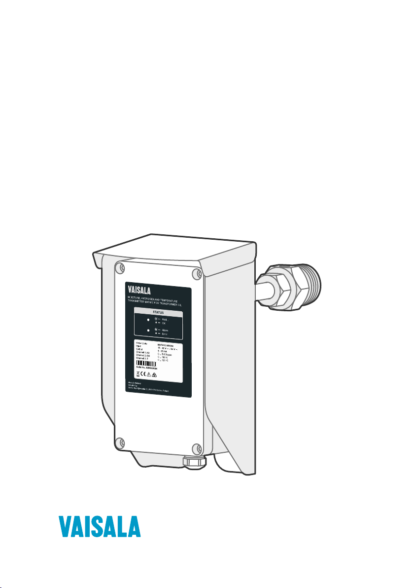
Vaisala Moisture, Hydrogen and Temperature
Transmitter for Transformer Oil
MHT410
Page 2

PUBLISHED BY
Vaisala Oyj
Vanha Nurmijärventie 21, FI-01670 Vantaa, Finland
P.O. Box 26, FI-00421 Helsinki, Finland
+358 9 8949 1
Visit our Internet pages at www.vaisala.com.
© Vaisala 2021
No part of this document may be
reproduced, published or publicly
displayed in any form or by any means,
electronic or mechanical (including
photocopying), nor may its contents be
modified, translated, adapted, sold or
disclosed to a third party without prior
written permission of the copyright holder.
Translated documents and translated
portions of multilingual documents are
based on the original English versions. In
ambiguous cases, the English versions are
applicable, not the translations.
The contents of this document are subject
to change without prior notice.
Local rules and regulations may vary and
they shall take precedence over the
information contained in this document.
Vaisala makes no representations on this
document’s compliance with the local
rules and regulations applicable at any
given time, and hereby disclaims any and
all responsibilities related thereto.
This document does not create any legally
binding obligations for Vaisala towards
customers or end users. All legally binding
obligations and agreements are included
exclusively in the applicable supply
contract or the General Conditions of Sale
and General Conditions of Service of
Vaisala.
This product contains software developed
by Vaisala or third parties. Use of the
software is governed by license terms and
conditions included in the applicable
supply contract or, in the absence of
separate license terms and conditions, by
the General License Conditions of Vaisala
Group.
Page 3

Table of contents
Table of contents
1. Safety................................................................................................................... 7
1.1 ESD protection.................................................................................................. 8
2. About this document.....................................................................................9
2.1 Documentation conventions..........................................................................10
2.2 Regulatory statements................................................................................... 10
2.2.1 FCC Part 15 compliance statement........................................................10
2.3 Trademarks........................................................................................................11
3. Product overview...........................................................................................12
3.1 Main features....................................................................................................12
3.2 Product parts and package contents............................................................13
3.3 Measurement parameters and units..............................................................15
3.4 Oil types............................................................................................................16
3.4.1 Oil type information in order code.........................................................16
3.4.2 Oil-specific coecients for ppmw moisture measurement................ 16
3.5 Data logging.....................................................................................................17
3.6 Status LEDs...................................................................................................... 17
4. Installation........................................................................................................ 19
4.1 Planning the installation................................................................................. 19
4.1.1 Recommended installation locations...................................................20
4.2 Mechanical installation....................................................................................21
4.3 Electrical installation......................................................................................28
4.4 Loop-powered display.................................................................................... 31
4.4.1 Wiring the loop-powered display..........................................................32
4.5 Checklist after installation............................................................................. 33
4.6 Oil fittings check after installation............................................................... 34
4.7 Removing the transmitter............................................................................. 34
4.8 Re-installing the transmitter in new location..............................................35
5. Analog output................................................................................................ 37
5.1 Analog output overrange behavior..............................................................37
6. Modbus............................................................................................................. 39
6.1 Overview of Modbus protocol support........................................................39
7. Vaisala Industrial Protocol........................................................................40
7.1 Connecting to MHT410 via service port........................................................41
7.1.1 Installing driver for the USB service cable............................................ 41
7.1.2 Connecting USB service cable...............................................................42
7.1.3 Configuring terminal application settings........................................... 42
7.2 Serial commands summary.......................................................................... 44
7.3 Device information and status commands................................................. 46
1
Page 4

MHT410 User Guide M211737EN-H
7.4 Serial line output and communication commands.....................................52
7.4.1 Measurement output commands.......................................................... 52
7.4.2 Measurement output format commands.............................................56
7.4.3 Serial line communication commands..................................................59
7.5 Analog output commands............................................................................ 63
7.6 Calibration and adjustment commands.......................................................67
7.7 Other commands............................................................................................68
8. DNP3 protocol.................................................................................................71
8.1 Taking DNP3 protocol into use...................................................................... 71
9. Vaisala MI70 Handheld Indicator........................................................... 73
9.1 MI70 indicator overview................................................................................ 73
9.1.1 MI70 indicator parts................................................................................73
9.1.2 Basic display.............................................................................................74
9.1.3 Graphical display..................................................................................... 74
9.1.4 Main menu................................................................................................ 75
9.2 Installing and recharging MI70 batteries..................................................... 75
9.3 Connecting MI70 to service port.................................................................. 76
9.4 Holding and saving the display.....................................................................76
9.5 Recording data................................................................................................77
9.5.1 Starting and stopping the recording.....................................................77
9.5.2 Viewing recorded data........................................................................... 78
9.5.3 Clearing data memory............................................................................78
9.6 Comparing readings with MM70 probe.......................................................78
9.7 Changing the rechargeable battery pack....................................................79
10. Vaisala Indigo520 Transmitter................................................................. 81
10.1 Taking Indigo520 Modbus settings into use in MHT410.............................81
10.2 Cabling and cable gland................................................................................ 82
10.3 Indigo520 and MHT410 wiring diagram......................................................83
10.4 MHT410 status messages shown in Indigo520...........................................84
10.5 Settings in Indigo520.....................................................................................84
11. Calibration and adjustment......................................................................85
11.1 H2 calibration and adjustment......................................................................85
11.1.1 Taking DGA sample and saving current H2 reading............................85
11.1.2 Entering DGA H2 reading to transmitter.............................................. 87
11.1.3 Clearing H2 calibration and adjustment............................................... 88
11.2 RS & T calibration and adjustment...............................................................89
12. Troubleshooting............................................................................................. 91
12.1 Error states.......................................................................................................91
12.2 Changing bleed screw................................................................................... 92
13. Technical data................................................................................................ 93
13.1 MHT410 specifications................................................................................... 93
13.2 Spare parts and accessories..........................................................................97
2
Page 5

Table of contents
13.3 Dimensions...................................................................................................... 98
13.4 Wiring diagrams.............................................................................................99
13.5 Recycling.........................................................................................................101
Appendix A: Operating principle..............................................................104
A.1 Method used for measuring moisture in oil...............................................105
A.2 Transformer oil..............................................................................................105
Appendix B: Modbus reference.................................................................107
B.1 Default Modbus communication settings..................................................107
B.2 Function codes..............................................................................................107
B.3 Data encoding............................................................................................... 107
B.3.1 32-bit floating point or 32-bit integer format....................................108
B.3.2 16-bit integer format.............................................................................108
B.4 Register map.................................................................................................108
B.5 Modbus registers.......................................................................................... 109
B.5.1 Measurement data registers................................................................ 109
B.5.2 Status registers........................................................................................ 111
B.6 Device identification objects........................................................................ 112
B.7 Exception responses......................................................................................112
Appendix C:
Moisture ppmw calculation for transformer oils.............113
C.1 Calculation model with average coecients..............................................113
C.2 Calculation model with oil-specific coecients.........................................113
Maintenance and calibration services........................................................115
Technical support........................................................................................... 115
Warranty........................................................................................................... 115
3
Page 6

MHT410 User Guide M211737EN-H
List of figures
Figure 1 MHT410 order code example (first digit 1 = mineral oil)........................ 16
Figure 2 Recommended installation locations.........................................................20
Figure 3 Loop-powered display 242003....................................................................32
Figure 4 Analog output overrange behavior............................................................ 38
Figure 5 Analog output overrange behavior............................................................64
Figure 6 MI70 indicator parts........................................................................................ 73
Figure 7 MI70 basic display............................................................................................74
Figure 8 Example of MI70 display with MHT410 in port I and
MM70 probe in port II. Shown parameters: aw (I), aw (II), Δ aw........ 79
Figure 9 Wiring between Indigo520 and MHT410 screw terminals....................83
Figure 10 MHT410 transmitter dimensions..................................................................98
Figure 11 Wiring Option 1: Wiring with four power supplies.
Separate loop-powering and galvanic isolation for
analog outputs. In transmitters ordered with Vaisala
cable CBL210392-5M, the cable is pre-wired according
to this option.....................................................................................................99
Figure 12 Wiring Option 2: Wiring with two power supplies.
Common loop-powering and galvanic isolation for
analog outputs............................................................................................... 100
Figure 13 Wiring Option 3: Wiring with one power supply. Non-
isolated configuration for analog outputs sharing
transmitter power supply............................................................................ 100
Figure 14 Wiring Option 4: Wiring with one power supply.
Alternative wiring to option 3, providing reduced
current loop area for analog outputs........................................................ 101
Figure 15 Materials for recycling...................................................................................102
Figure 16 Measuring hydrogen and moisture in oil with MHT410....................... 104
Figure 17 Water solubility of transformer oils versus temperature.
The margins show the range of variation of water
solubility found in mineral oils....................................................................106
4
Page 7

List of tables
Table 1 Document versions (English)...........................................................................9
Table 2 Related manuals.................................................................................................. 9
Table 3 Analog output values in dierent transmitter statuses..........................37
Table 4 Default serial interface settings....................................................................40
Table 5 Service port serial interface settings...........................................................43
Table 6 Serial commands.............................................................................................. 44
Table 7 ? command.........................................................................................................46
Table 8 alarm command................................................................................................ 47
Table 9 errlog command............................................................................................... 48
Table 10 errs command....................................................................................................49
Table 11 help command...................................................................................................50
Table 12 system command............................................................................................. 50
Table 13 time command....................................................................................................51
Table 14 vers command.................................................................................................... 51
Table 15 intv command.................................................................................................... 52
Table 16 log command..................................................................................................... 52
Table 17 r command..........................................................................................................55
Table 18 send command.................................................................................................. 55
Table 19 form command.................................................................................................. 56
Table 20 Output parameters for form command...................................................... 57
Table 21 Modifiers for form command.........................................................................58
Table 22 unit command....................................................................................................59
Table 23 addr command.................................................................................................. 59
Table 24 close command.................................................................................................60
Table 25 open command................................................................................................. 60
Table 26 sdelay command.............................................................................................. 60
Table 27 seri command..................................................................................................... 61
Table 28 smode command.............................................................................................. 62
Table 29 aerr command................................................................................................... 63
Table 30 aover command.................................................................................................63
Table 31 asel command................................................................................................... 64
Table 32 atest command..................................................................................................66
Table 33 cdate command.................................................................................................67
Table 34 ctext command..................................................................................................67
Table 35 h2 da and h2 db commands.......................................................................... 68
Table 36 h2 x command................................................................................................... 68
Table 37 dnp3 addr command....................................................................................... 68
Table 38 filt command...................................................................................................... 69
Table 39 frestore command............................................................................................69
Table 40 reset command..................................................................................................70
Table 41 oil command...................................................................................................... 70
Table 42 h2 is command.................................................................................................. 70
Table 43 Default communication settings....................................................................71
Table 44 MHT410 communication settings for Indigo520.......................................81
Table 45 MHT410 status messages shown in Indigo520.........................................84
List of tables
5
Page 8

MHT410 User Guide M211737EN-H
Table 46 Possible error messages via Vaisala Industrial Protocol.........................91
Table 47 MHT410 measurement performance...........................................................93
Table 48 MHT410 operating environment...................................................................94
Table 49 MHT410 inputs and outputs...........................................................................94
Table 50 MHT410 mechanical specifications.............................................................. 95
Table 51 MHT410 compliance.........................................................................................96
Table 52 Display with relays (external option).......................................................... 96
Table 53 MHT410 spare parts and accessories.......................................................... 97
Table 54 Vaisala cable CBL210392-5M wire colors (when pre-wired)................99
Table 55 Materials for recycling....................................................................................103
Table 56 Optimal sensor positions.............................................................................. 104
Table 57 Default Modbus RTU communication settings....................................... 107
Table 58 Supported Modbus function codes............................................................107
Table 59 Interpretation of 16-bit signed integer values.........................................108
Table 60 Modbus register blocks................................................................................. 109
Table 61 Modbus measurement data registers (read-only).................................109
Table 62 Modbus status registers (read-only)............................................................111
Table 63 Modbus device status bits.............................................................................. 111
Table 64 Device identification objects.........................................................................112
Table 65 Modbus exception responses........................................................................112
6
Page 9
Chapter 1 – Safety
1. Safety
Vaisala Moisture, Hydrogen and Temperature Transmitter MHT410 for Transformer Oil delivered
to you has been tested for safety and approved as shipped from the factory. Note the
following precautions:
CAUTION!
before installing the product.
WARNING!
to minimize shock hazard.
DANGER!
Pay attention to transmitter installation depth and possible energized parts
inside the power transformer to minimize electric shock hazard and equipment
damage.
CAUTION!
documentation. Improper modification or use may lead to safety hazards,
equipment damage, failure to perform according to specification, or decreased
equipment lifetime.
CAUTION!
installed. The probe body goes through the valve into the oil flow, and trying to
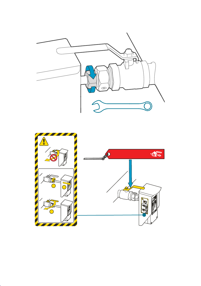
close the valve will damage the probe body and/or the valve.
If you must close the ball valve while the transmitter is on the valve, first open
the small tightening nut and pull the probe body out as far as possible. Then
close the valve.
Read the Quick Guide (including installation instructions) carefully
Ground the product and verify installation grounding periodically
Severe risk of death and of damage to transformer:
Do not modify the unit or use it in ways not described in the
Do not try to close the ball valve when the transmitter is fully
CAUTION!
step on the transmitter when the transmitter is installed.
CAUTION!
installation site.
To avoid damage to the installation valve of the transformer, do not
Follow the safety regulations related to the application and
7
Page 10

MHT410 User Guide M211737EN-H
1.1 ESD protection
Electrostatic Discharge (ESD) can damage electronic circuits. Vaisala products are adequately
protected against ESD for their intended use. However, it is possible to damage the product by
delivering electrostatic discharges when touching, removing, or inserting any objects in the
equipment housing.
To avoid delivering high static voltages to the product:
• Handle ESD‑sensitive components on a properly grounded and protected ESD workbench
or by grounding yourself to the equipment chassis with a wrist strap and a resistive
connection cord.
• If you are unable to take either precaution, touch a conductive part of the equipment
chassis with your other hand before touching ESD‑sensitive components.
• Hold component boards by the edges and avoid touching component contacts.
8
Page 11

Chapter 2 – About this document
2. About this document
Table 1 Document versions (English)
Document code Date Description
M211737EN-H March 2021 This document.
New chapters:
• Vaisala Indigo520 Transmitter (page 81)
• Clearing H2 calibration and adjustment (page 88)
Updated content:
• Added silicone oil to the list of supported oils
• Serial commands summary (page 44)
• Calibration and adjustment commands (page 67)
• Error states (page 91)
• MHT410
• Status registers (page 111)
M211737EN-G November 2018 Previous version. Added natural and synthetic ester oil
support information and instructions on checking the oil
type set at the factory from the product label. Added
instructions on
calculation coecients. Clarified the information on the
temperature range for accurate measurement in hydrogen
and temperature accuracy specifications and added
sensor head temperature tolerance specification. Added
instructions on using a safety pin with a warning label to
lock the valve handle in open position after installation.
M211737EN-F May 2018 Updated installation instructions regarding PTFE tape and
installation depth. Added DNP3 protocol information.
Added clarification about using the RS-485 line of the
screw terminals with Modbus or Vaisala Industrial Protocol.
Added maximum power consumption specification.
Added new parameter options for analog outputs: daily,
weekly, and monthly ROC and 24-hour average for H2 and
H2O. Added
change (ROC) readings. Changed unit "ppm" to "ppmv"
for H2 and to "ppmw" for H2O.
specifications (page 93)
configuring oil-specific moisture in oil
clarification about the calculation of rate of
Table 2 Related manuals
Document code Description
M211736EN Vaisala MHT410 Quick Guide
M212287EN Vaisala Indigo520 User Guide
M211784EN Loop-Powered Display 242003 for MHT410 Technical Note
9
Page 12

MHT410 User Guide M211737EN-H
2.1 Documentation conventions
WARNING!
follow instructions carefully at this point, there is a risk of injury or even death.
CAUTION!
follow instructions carefully at this point, the product could be damaged or
important data could be lost.
Note highlights important information on using the product.
Tip gives information for using the product more eciently.
Lists tools needed to perform the task.
Indicates that you need to take some notes during the task.
Warning alerts you to a serious hazard. If you do not read and
Caution warns you of a potential hazard. If you do not read and
2.2 Regulatory statements
2.2.1 FCC Part 15 compliance statement
This equipment has been tested and found to comply with the limits for a Class A digital
device, pursuant to part 15 of the FCC Rules. These limits are designed to provide reasonable
protection against harmful interference when the equipment is operated in a commercial
environment. This equipment generates, uses, and can radiate radio frequency energy and, if
not installed and used in accordance with the instruction manual, may cause harmful
interference to radio communications. Operation of this equipment in a residential area is likely
to cause harmful interference in which case the user will be required to correct the interference
at his own expense.
10
Page 13

Chapter 2 – About this document
CAUTION!
by the party responsible for compliance could void the user's authority to
operate the equipment.
This device complies with part 15 of the FCC Rules. Operation is subject to the
following two conditions: (1) This device may not cause harmful interference, and
(2) this device must accept any interference received, including interference that
may cause undesired operation.
Changes or modifications to this equipment not expressly approved
2.3 Trademarks
HUMICAPâ is a registered trademark of Vaisala Oyj.
Modbusâ is a registered trademark of Schneider Automation Inc.
All other product or company names that may be mentioned in this publication are trade
names, trademarks, or registered trademarks of their respective owners.
11
Page 14

MHT410 User Guide M211737EN-H
3. Product overview
Vaisala Moisture, Hydrogen and Temperature Transmitter MHT410 for Transformer Oil is
designed for online monitoring of insulating oil in power transformers. The transmitter
provides an accurate real-time measurement result of moisture, hydrogen and temperature
measured in oil, enabling reliable conclusions on the transformer's condition without delay.
The transmitter provides digital and analog outputs of all the measured parameters.
3.1 Main features
• Reliable online measurement of transformer oil for the following parameters:
• Moisture: relative saturation (%RS), water activity, and water content (ppmw)
• Hydrogen concentration (ppmv in oil)
• Temperature (°C and °F)
• Compatible with mineral oils, natural ester oils, synthetic ester oils, and silicone oils
• No need to take oil samples for measurement
• Installable and retro-fittable on a ball valve (ball valve thread: female 1.5" NPT)
• Low maintenance requirements due to excellent long term stability
• Outputs
• Digital: Modbus, DNP3, and Vaisala industrial protocol over RS-485
• Analog: three channels with scalable current output
• Status indication LEDs in the front panel
• Built-in data logging
• USB connectivity for service connections using an optional USB M8 cable
• Display options:
• Loop-powered display for continuous use
• MI70 handheld meter for temporary use
• Compatible with Vaisala Indigo500 series transmitters
More information
‣
Oil types (page 16)
‣
Status LEDs (page 17)
‣
Data logging (page 17)
‣
Connecting to MHT410 via service port (page 41)
‣
Loop-powered display (page 31)
‣
Vaisala MI70 Handheld Indicator (page 73)
‣
Technical data (page 93)
12
Page 15
59876
123
4
10
Chapter 3 – Product overview
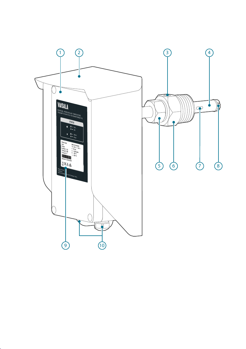
3.2 Product parts and package contents
13
Page 16

5 mm
3 mm
111413
12
+
MHT410 User Guide M211737EN-H
No. Item
1 = Electronics housing.
The front cover is additionally connected to the housing with a grounding wire.
2 = Weather shield
3 = Bleed screw
4 = Probe body
5 = Small tightening nut, used to adjust and fix the depth of the transmitter in the valve.
You can move the tightening nut and the mounting nut along the probe body.
6 = Mounting nut, used to fasten the transmitter in the ball valve.
You can move the tightening nut and the mounting nut along the probe body.
7 = Hydrogen sensor
8 = Moisture and temperature sensors under the filter
9 = Product label
10 = Lead-throughs (2 pcs) with a minimum of one cable gland (size M20x1.5) or conduit
Installation Kit:
11 = PTFE tape roll
12 = Allen keys (3 mm and 5 mm)
13 = Extra bleed screw and sealing ring
14 = Extra terminal blocks (4 x 4 screw terminals)
fitting.
Unused lead-throughs are plugged.
More information
‣
Dimensions (page 98)
14
Page 17

Chapter 3 – Product overview
3.3 Measurement parameters and units
Parameter Abbreviation Unit
H2 concentration in oil
• 1 h average
• 24 h average
Rate of change of H2 concentration
In a day Daily ROC ppmv/day
In a week Weekly ROC ppmv/week
In a month Monthly ROC ppmv/month
Moisture in oil
Relative saturation RS %RS
Water activity aw (=RS/100) (no unit)
H2O concentration in oil
(current)
H2O concentration in oil (24 h
average)
Rate of change of H2O concentration in oil
In a day Daily ROC ppmw/day
In a week Weekly ROC ppmw/week
In a month Monthly ROC ppmw/month
Temperature
Oil temperature T °C or °F
H2 ppm
H2O ppm
H2O ppm
v
w
w
The rate of change (ROC) for H2 and for H2O shows the dierence in ppm between the latest
24-hour average and the 24-hour average 1 day ago (daily ROC), 7 days ago (weekly ROC), or
30 days ago (monthly ROC). ROC readings are updated every 12 hours.
After starting up or resetting the transmitter, ROC readings are available as follows:
• Daily ROC: after 2 days
• Weekly ROC: after 8 days
• Monthly ROC: after 31 days
Before the ROC readings are available, the ROC measurement registers in digital outputs
contain a "NaN" value, and the ROC analog outputs are set to 3.0 mA (= measurement not
ready).
15
Page 18

MHT410 1 B E G 0
1
MHT410 User Guide M211737EN-H
3.4 Oil types
MHT410 is compatible with the following oil types:
• Mineral oils
• Natural ester oils
• Synthetic ester oils
• Silicone oil
CAUTION!
for the unit at the factory. Using the transmitter with a dierent oil type requires
sending the unit to Vaisala for reconfiguration.
The oil type that MHT410 measures (mineral oils, natural ester oils, synthetic ester oils, or
silicone oil) is selected when ordering the transmitter. For instructions on checking the oil type
set at the factory from the product label, see Oil type information in order code (page 16).
Never use MHT410 with any other oil type than the one configured
3.4.1 Oil type information in order code
MHT410 has been configured for a specific oil type based on the selection made when
ordering the transmitter, and must not be used with other oil types. The oil type configuration
set at the factory can be checked from the first digit (1, 2, 3, or 4) of the order code in the
MHT410 product label.
Figure 1 MHT410 order code example (first digit 1 = mineral oil)
First digit of the order code. The oil type configuration is shown in the first digit as 1, 2, 3,
1
or 4:
• 1 = Mineral oils (shown)
• 2 = Natural ester oils
• 3 = Synthetic ester oils
• 4 = Silicone oils
3.4.2 Oil-specific coecients for ppmw moisture measurement
MHT410 can be ordered with ppmw moisture output (average mass concentration of water in
oil). The calculation model that MHT410 uses for ppmw measurement is based on the average
water solubility behavior of transformer oils (see Calculation model with average coecients
(page 113)). If additional accuracy is required, you can configure oil-specific coecients into
MHT410 using Vaisala Industrial Protocol serial commands (see Table 41 (page 70)), or contact
Vaisala about setting the coecients.
16
Page 19

Chapter 3 – Product overview
More information
‣
Moisture ppmw calculation for transformer oils (page 113)
‣
Other commands (page 68)
3.5 Data logging
The transmitter automatically saves the measurement readings and other events in a log every
12 hours (configurable interval). The log can contain approximately 32000 entries.
The following events are logged:
• Hydrogen (ppmv) reading as 1 h average or 24 h average
• Moisture in oil (%RS and ppmw) and temperature (°C) readings as instant values or 24 h
averages
• Power outages
• Short power outages that don't turn o transmitter power (flagged "UPS")
• Long power outages that turn o transmitter power (flagged first as "UPS" and then
as "Reset")
• Manual resets (flagged as "Reset")
• Uptime and total operating time
• Occasions of exceeding hydrogen alarm level (optional)
To view the log and change the logging settings, use Vaisala Industrial Protocol.
You can save the log as a file from PuTTY by configuring the following settings in
PuTTY before opening the connection:
In the Session > Logging view:
• Session logging: Select "Printable output".
• Log file name: Type a name for the log file (use the file extension .txt) and
browse to the save location.
To prevent the log from getting very long, consider saving and then clearing the
log every few years.
More information
‣
Vaisala Industrial Protocol (page 40)
‣
Measurement output commands (page 52)
3.6
Status LEDs
When the transmitter is ON, one of the LEDs is always illuminated (solid or blinking). If no LED
is illuminated, the transmitter is OFF.
17
Page 20

Wait...
OK
Alarm
Error
MHT410 User Guide M211737EN-H
LED color and text Description
Green, blinking:
Transmitter is preparing H2 measurement after start-up or reset.
Green, solid:
Red, blinking:
Red, solid:
Transmitter is measuring.
H2 concentration is above the alarm limit.
Transmitter is in error state.
18
Page 21

4. Installation
Before you install the transmitter:
• Go through the check list in section Planning the installation (page 19).
• Read this whole guide carefully.
Chapter 4 – Installation
CAUTION!
configured for MHT410. See Oil type information in order code (page 16).
The installation instructions in this section are the same as in the MHT410 Quick
Guide.
Make sure the oil type of the transformer matches the oil type
4.1 Planning the installation
• Choose the installation location on the transformer (see Recommended installation
locations (page 20)).
CAUTION!
from the valve specifications. The correct thread of the valve is female 1.5"
NPT. Do not install the transmitter in a valve with a dierent thread. For
example, the R thread is incorrect. If you use a dierent thread than female
1.5" NPT, your equipment may be damaged and the connection is not leak
tight. If you are not sure which thread your installation valve has, verify the
thread with a 1.5" NPT thread gauge.
• Make sure the oil type of the transformer matches the one configured for MHT410
(mineral oil, natural ester oil, synthetic ester oil, or silicone oil).
• Make sure you have all the required tools for installing the transmitter. The required tools
are presented in the installation instructions.
• Choose the output signals: analog and/or digital.
• Choose the electrical wiring option. If the transmitter was ordered with the Vaisala cable
CBL210392-5M, the cable is already pre-connected to the transmitter according to Wiring
Option 1.
Make sure the installation valve and threads are appropriate
More information
‣
Wiring diagrams (page 99)
19
Page 22

MHT410 User Guide M211737EN-H
4.1.1 Recommended installation locations
The probe must always be installed in a valve. The correct thread of the valve is female 1.5"
NPT. Do not install the transmitter in a valve with a dierent thread. For example, the R thread
is incorrect. If you use a dierent thread than female 1.5" NPT, your equipment may be
damaged and the connection is not leak tight.
Figure 2 Recommended installation locations
Recommendation
Recommended:
Straight section in the
radiator’s outlet pipe.
20
Description
This is the best location for the transmitter.
The oil is measured in flow, which makes the oil sample
representative and instant. This is essential especially for correct
oil moisture measurement.
Compared to the radiator inlet pipe, oil in the outlet pipe is
cooled, preventing unnecessary heating of the sensors and the
transmitter.
Page 23

Recommendation Description
Possible alternative:
Wall of the oil tank, high
enough from the bottom to
enable proper oil movement.
An instrumentation valve is recommended. This is a typical valve
that is meant for oil analysis.
Moisture response time is moderate depending on the oil volume
and transmitter installation.
DANGER!
damage to transformer:
Pay attention to transmitter installation depth
and possible energized parts inside the power
transformer to minimize electric shock hazard
and equipment damage.
The moisture response can be poor due to static oil flow. There is
also a risk of separated water (leading to wrong results) and oil
Not recommended:
Drain valve of the oil tank.
sludge (risk of sensor contamination and clogged filters).
4.2 Mechanical installation
Chapter 4 – Installation
Severe risk of death and of
CAUTION!
Before you install the transmitter:
• Make sure there is no negative pressure in the transformer. If there is negative
pressure when you open the bleed screw during installation, air will flow into
the transformer oil tank.
• Do not open the ball valve on the transformer until you are instructed to do so
in this guide.
• Make sure the bleed screw on the mounting nut is closed.
• 2 wrenches (50 mm and 36 mm)
• Allen key (3 mm, provided)
• PTFE tape (provided)
• Gloves
• Bucket and cloth
21
Page 24
MHT410 User Guide M211737EN-H
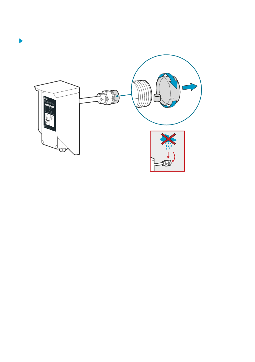
1. Remove the protective cap with sorbent packet from the mounting nut.
In case of rain, do not let any water fall on the filter.
22
Page 25
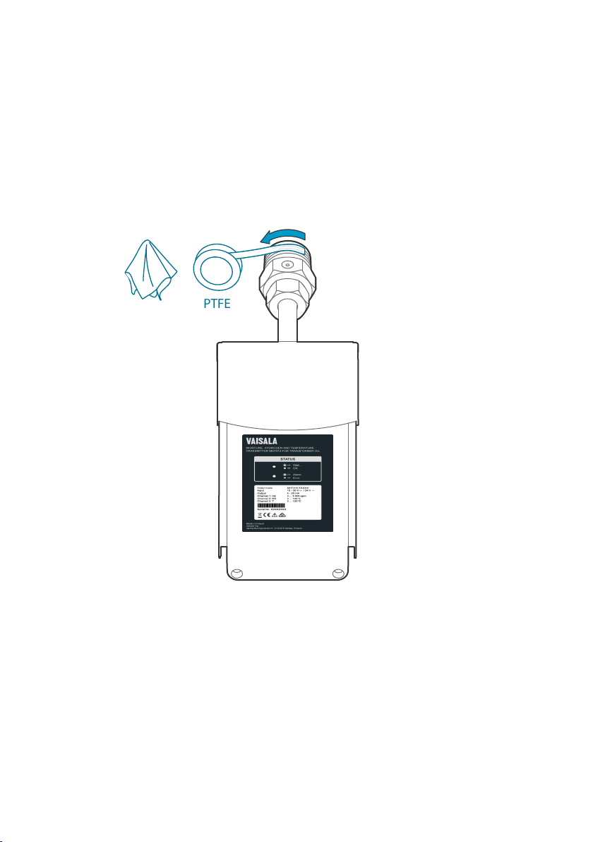
PTFE
Chapter 4 – Installation
2. Apply PTFE tape tightly on the mounting nut threads.
a. Before you start, clean the threads with a cloth.
b. To make sure you wrap the tape in the correct direction, hold the transmitter so that
the product label is facing you and the mounting nut points away from you.
c. Start wrapping counter-clockwise from the second thread on the tip of the mounting
nut.
d. Wrap each round very tightly about half way on top of the previous round so that the
tape overlaps. Stretch the tape for optimal tightness. Apply a couple of rounds of
tape.
23
Page 26

OPEN
max. 3 × 360°
MHT410 User Guide M211737EN-H
3. Make sure the bleed screw is closed. Fasten the mounting nut on the ball valve to finger-
tightness with your hand. Leave the bleed screw directly on top of the nut.
If you cannot position the bleed screw on top of the mounting nut by tightening just with
your hand, you can use a wrench (50 mm) to turn the mounting nut a maximum of a ½
turn.
CAUTION!
fastened it on the valve, you must remove the transmitter from the valve,
remove the PTFE tape, and start again from step 2 with new PTFE tape.
4. With a 3 mm Allen key, loosen the bleed screw. Place a bucket under the mounting nut.
If you need to loosen the mounting nut after you have
24
Page 27

CLOSE
SLOW
Chapter 4 – Installation
5. Start opening the valve very carefully to let air out through the bleed screw.
CAUTION!
If you open the valve too quickly, the air inside the mounting
nut will flow into the transformer instead.
When oil flows out, close the bleed screw. Clean the area with a cloth and open the ball
valve fully.
6. Continue tightening the mounting nut with a wrench. Be very careful not to over-tighten
the connection. Approximately 5 ... 8 mm of the mounting nut threads remain outside the
valve.
If the connection leaks after you have tightened the mounting nut, check the
thread type of the installation valve.
• If the valve thread is other than female 1.5" NPT (incorrect), do not
install the transmitter in that valve.
• If the valve thread is female 1.5" NPT (correct), close the valve, open
the mounting nut and remove the transmitter, remove old PTFE tape
and apply a thicker layer of new PTFE tape. Then continue from
step 3.
25
Page 28
180 ... 190 mm
200 mm
MHT410 User Guide M211737EN-H
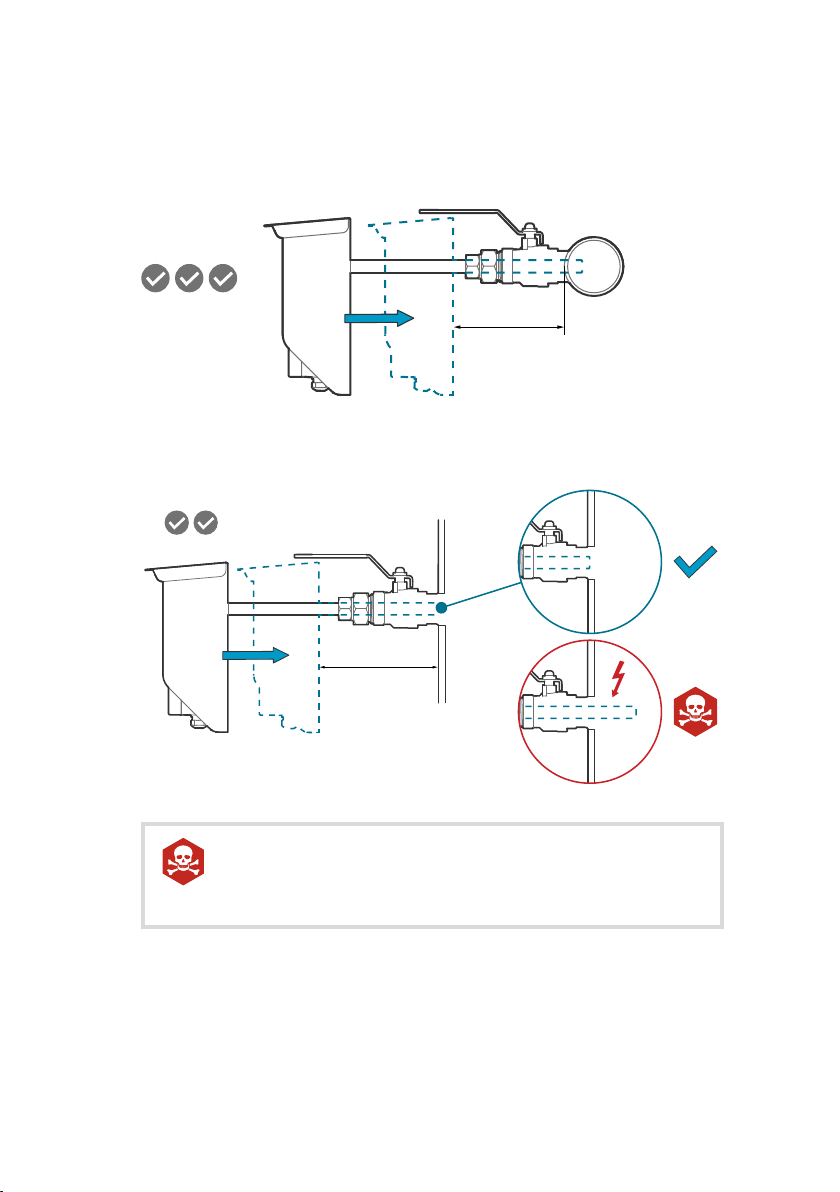
7. Push the probe to the correct depth. The correct depth depends on where the installation
valve is located: radiator pipe or transformer wall.
• Valve in radiator pipe: Install the probe so that the back of the weather shield is
180 ... 190 mm from the pipe surface.
• Valve in transformer wall: Install the probe so that the back of the weather shield is
200 mm from the transformer wall.
DANGER!
Severe risk of death and of damage to transformer:
Pay attention to transmitter installation depth and possible energized
parts inside the power transformer to minimize electric shock hazard
and equipment damage.
When the probe is in the correct depth, turn the transmitter 90 degrees two to three
times to remove any air bubbles from the sensor area.
26
Page 29
DO NOT CLOSE VALVE
WHEN TRANSMITTER
IS INSTALLED!
HOW TO CLOSE VALVE:
1
2
3
DO NOT CLOSE VALVE
WHEN TRANSMITTER
IS INSTALLED!
HOW TO CLOSE VALVE:
1
2
3
PULL INSTRUMENT OUT
BEFORE CLOSING VALVE
Chapter 4 – Installation
8. Tighten the small tightening nut with a wrench until the probe is securely fastened.
9. Press the caution sticker on the MHT410 weather shield or other visible location nearby,
and lock the handle of the valve in the open position with the safety pin.
More information
‣
Dimensions (page 98)
27
Page 30
+
CH2
– CH2
+
CH1
– CH1
SHLD
SHLD
RS
GND
D –
D
+
+
Vs
– Vs
3 4 5 6 7 8
9
10 11 12 13 14 15 16
RS-485
NALOG OUTPUTS
SERVICE
PORT
19200 b/s, 8, n, 1
POWER
SERIAL COMMANDS
Device information ?
List of errors ERRS
List of commands HELP
Modbus default
address: 240
RS-485
TERMINATION
ON
OFF
See manual for further
commands.
www.vaisala.com/MHT410
MHT410 User Guide M211737EN-H
4.3 Electrical installation
When connecting MHT410 to the Indigo520 transmitter, see also Indigo520 and
MHT410 wiring diagram (page 83).
If MHT410 was ordered with the Vaisala cable CBL210392-5M, the cable is already
pre-connected to MHT410 according to Wiring Option 1.
If cable is not pre-wired:
• Allen key (5 mm, provided)
• 2 medium wrenches (24 mm)
• Flat head screwdriver (2.5 mm)
• Wire-cutting pliers
• Suitable cable. You can order the following cables from Vaisala:
• 5 m shielded PUR cable (order code: CBL210392-5MSP)
• 10 m shielded PUR cable (order code: CBL210392-10MSP)
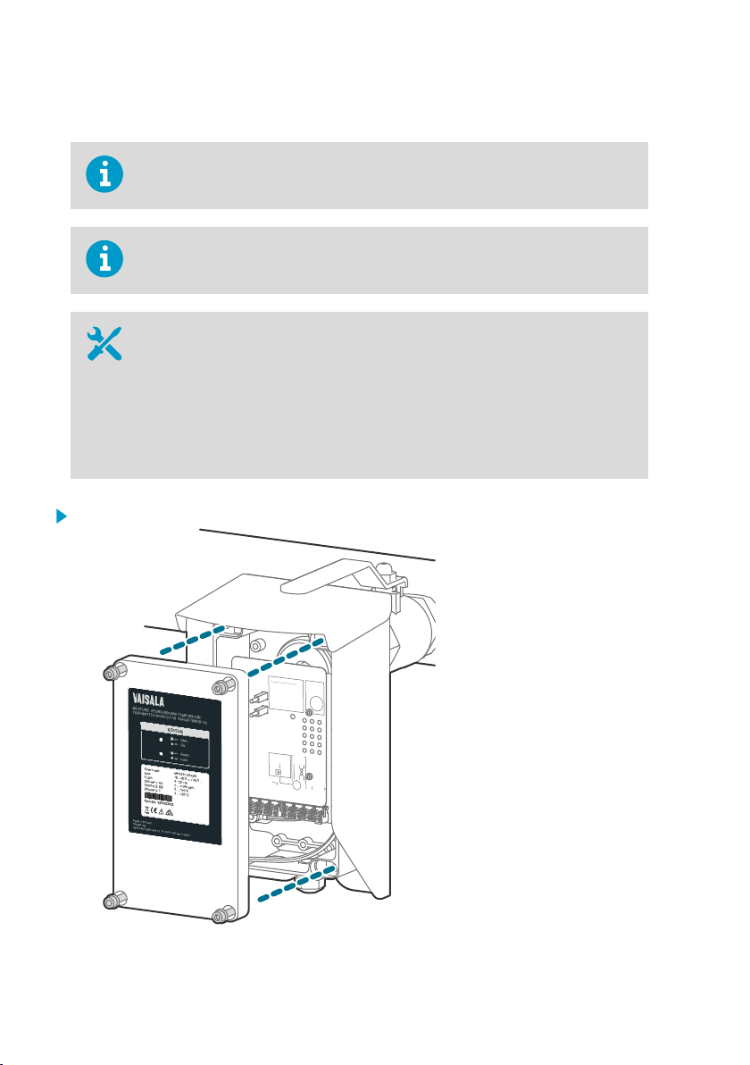
1. Open the electronics housing with a 5 mm Allen key to access the screw terminals.
28
Page 31

Chapter 4 – Installation
2. Hold the upper nut of the cable gland in place with a wrench (24 mm), and loosen the
sealing nut of the gland with another wrench (24 mm).
3. Lead the cable through the sealing nut and the rubber seal. Turn the shield over the edge
of the rubber seal.
29
Page 32

+
CH3
– CH3
+
CH2
– CH2
+
CH1
– CH1
SHLD
SHLD
RS
GND
D –
D
+
+
Vs
– Vs
1 2 3 4 5 6 7 8 9 10 11 12 13 14 15 16
RS-485
ANALOG OUTPUTS
POWER
Modbus default
address: 240
RS-485
TERMINATION
ON
OFF
MHT410 User Guide M211737EN-H
4. Lead the cable through the cable gland. Push the rubber seal back in place with the
shield. Cut o any excess shield. Tighten the sealing nut with wrench (24 mm).
5. Pull the screw terminal blocks (2 pcs) o from the circuit board.
6. Connect the wiring to the detachable screw terminals according to your chosen wiring
option. Note that wiring for digital output (RS-485) is the same in all wiring options.
30
Page 33

Chapter 4 – Installation
7. When you are finished with the wiring, plug the screw terminals back in and close the
electronics housing.
More information
‣
Wiring diagrams (page 99)
‣
Wiring diagrams (page 99)
4.4 Loop-powered display
The analog outputs of the transmitter can be connected to an external loop-powered LED
display (order code 242003). The display is a pre-configured Nokeval 302 display intended for
Vaisala MHT410 hydrogen channel measurements.
The display also includes two alarm relays to trigger an external hydrogen warning and alarm.
This display can be configured for other parameters (moisture/temperature in oil). If needed,
you can install up to three displays, each showing a dierent parameter.
The default display settings are presented in the Vaisala Technical Note inside the display
package. If needed, configure the display functions and scaling according to the
manufacturer's instructions delivered with the display. Manufacturer’s documentation is also
available from www.nokeval.com.
31
Page 34

MHT410 User Guide M211737EN-H
Figure 3 Loop-powered display 242003
The loop resistance of the display must be included in the loop resistance
calculation for the complete current loop. For the loop resistance of the display,
refer to the manufacturer’s documentation.
More information
‣
Wiring the loop-powered display (page 32)
4.4.1 Wiring the loop-powered display
If one of the cable lead-throughs on your transmitter is plugged and you want to
use that lead-through for the Nokeval display cable, you can order a cable gland
from Vaisala.
32
Page 35

1 2 3 4 5 6 7 8
+CH3
-CH3
+CH2
-CH2
+CH1
-CH1
SHLD
SHLD
1
2
3
Nokeval Display
mA-
mA+
7 6 5 4
A1(hi) A2(hihi)
4...20 mA
R
= 0...500
Ω
15...30 V DC,
L
power supply
for analog channel
and display
Chapter 4 – Installation
1. Connect the loop-powered display to the transmitter as shown in the following wiring
diagram. In the diagram, the display is connected to analog output Channel 1 according to
Wiring Option 1.
All the Wiring Options (1, 2, 3, and 4) have the same principle for connecting the
display:
• Wire from port 1 of the display connects to the minus port of the transmitter's
analog output channel (for example, to "-CH1").
• Wire from port 2 of the display connects to where the minus port wire of the
analog output channel would have connected without the display.
More information
‣
Spare parts and accessories (page 97)
‣
Wiring diagrams (page 99)
4.5
Checklist after installation
After the installation, check the following indicators to make sure the installation was
successful:
• No oil is leaking from the transformer and the transmitter.
If the connection leaks after you have tightened the mounting nut, the probable reason is
that the PTFE tape was applied incorrectly or the valve thread is other than female 1.5"
NPT.
33
Page 36

MHT410 User Guide M211737EN-H
• The H2 level LED indicator settles to a solid green. Note that it can take up to 30 minutes
for the H2 level measurement to settle after start-up or reset.
• Solid green indicates that the H2 level is below alarm limit.
• Blinking red indicates that the H2 level is above alarm limit (by default, the alarm is
o).
• After the initial stabilization period (approx. 24 h power on), the reading is correct.
4.6 Oil fittings check after installation
After the first month of continuous use, all oil fittings should be checked for leaks.
An annual check thereafter is recommended.
4.7 Removing the transmitter
To disconnect wiring:
• Allen key (5 mm, provided)
• 2 medium wrenches (24 mm)
• Flat head screwdriver (2.5 mm)
To remove transmitter:
• Large wrench (50 mm)
• Medium wrench (36 mm)
• Gloves
• Bucket and cloth
CAUTION!
installed. The probe body goes through the valve into the oil flow, and trying to
close the valve will damage the probe body and/or the valve.
1. If needed, disconnect the wiring:
a. Open the front cover and disconnect the wires from the detachable screw terminals.
b. Hold the upper nut of the cable gland in place with a wrench (24 mm), and loosen the
sealing nut of the gland with another wrench (24 mm).
c. Pull the cable out of the cable gland.
d. Re-attach the cable gland in its place.
2. Put a bucket under the ball valve to catch any oil falling from the valve.
34
Do not try to close the ball valve when the transmitter is fully
Page 37

Chapter 4 – Installation
3. Loosen the small tightening nut with a wrench.
To keep the larger mounting nut from opening, hold it in place with a wrench
as you are opening the smaller tightening nut.
4. Pull the transmitter outward so that the probe body is out of the ball valve.
5. Close the ball valve.
6. Open the mounting nut with a wrench and pull the transmitter out. Use the cloth to clean
up any spills.
Always make sure the bleed screw is closed before you turn the mounting
nut with a wrench.
4.8 Re-installing the transmitter in new location
If you re-install the transmitter in a new location, you must initialize the transmitter after the
re-installation by connecting to the service port and giving the initialization command using
Vaisala Industrial Protocol.
1. Remove the transmitter. See Removing the transmitter (page 34).
2. Install the transmitter in the new location as instructed in Installation (page 19) and its
subsections.
3. Connect to the transmitter via the service port and start communication using Vaisala
Industrial Protocol.
a. Connect to the service port (Connecting to MHT410 via service port (page 41)).
b. If needed, install the USB driver (Installing driver for the USB service cable
(page 41)).
c. Connect the USB cable (Connecting USB service cable (page 42)).
d. Configure the terminal application settings (Configuring terminal application settings
(page 42)).
4. Start the initialization sequence by issuing the command h2. The transmitter starts
outputting H2 measurement data.
> h2
Start hydrogen measurement module command line operation, quit by pressing
+
15832291.00 33.5719 50.06586 209.87 8413520 8410294 106 0.0 0 28.7938 0
15832292.00 33.5852 50.06617 209.82 8413484 8410254 106 0.0 0 28.7938 0
...
35
Page 38

MHT410 User Guide M211737EN-H
5. Stop the output by pressing the Esc key:
...
15832292.00 33.5852 50.06617 209.82 8413484 8410254 106 0.0 0 28.7938 0
<"Esc key">
H2scan:
6. Give the initialization command is, and when asked to erase the data log, confirm by
pressing the y key.
H2scan: is
Clearing old data:
...wait...Erase the Data Log (Y/N)? y
Clearing log
; SSN=B13.21L.10306TN1X, FW=3.85F , MDN=104400-FF02-P1, DF=0xB4B4s, L
TimeSec PcbTemp SnsrTemp HCurrent Res1Adc AdjRes1 H2Res.ppm
H2.ppm H2_DG.ppm OilTemp H2_G.ppm H2_SldAv Messages
7. Start the H2 measurement output again by pressing the v key.
v
15832363.00 31.9850 30.88629 0.00 8087342 8087342 641 - - - - - htr_off
wait
15832364.00 31.9565 30.84680 0.00 8086663 8086663 582 - - - - - htr_off
wait
...
8. Finish the initialization sequence by pressing the + key.
...
15832364.00 31.9565 30.84680 0.00 8086663 8086663 582 - - - - - htr_off
wait
<"+ key">
Quit hydrogen measurement module command line operation
9. Close the PuTTY terminal application.
10. Disconnect from the service port and close the transmitter cover.
36
Page 39

Chapter 5 – Analog output
5. Analog output
There are three analog output channels available for H2, moisture in oil, and temperature using
4 ... 20 mA current outputs.
The parameter for each output is configured at the factory according to order. If needed, you
can change the parameters using the asel command via Vaisala Industrial Protocol.
Table 3 Analog output values in dierent transmitter statuses
Transmitter status Analog output value
Normal 4 ... 20mA
Error 3.5 mA (default)
Measurement not ready 3.0 mA
More information
‣
Analog output commands (page 63)
5.1
Analog output overrange behavior
If the measured hydrogen, moisture and temperature levels go below or above their scaled
range, the analog output is clipped at the low (4 mA) or high (20 mA) end of the output range.
This means the analog output will not indicate measurement readings that are outside the
scaled ranges.
If needed, you can allow the analog outputs to extend 10 % of the range over 20 mA using the
aover command via Vaisala Industrial Protocol. With this extension, the allowed range for
analog outputs is 4 ... 21.6 mA. The aover command does not aect the scaling of the outputs.
You can also change the scaling of the outputs for each channel using the asel command via
Vaisala Industrial Protocol.
37
Page 40

20 mA
21.6 mA
4 mA
Low end
of scale
High end
of scale
High end
of scale
+10 %
of scale
Analog output
Analog output extended at high end of range
CURRENT
OUTPUT
MEASURED
VALUE
MHT410 User Guide M211737EN-H
Figure 4 Analog output overrange behavior
More information
‣
Analog output commands (page 63)
38
Page 41

Chapter 6 – Modbus
6. Modbus
6.1 Overview of Modbus protocol support
MHT410 can be accessed using the Modbus serial communication protocol on the RS-485 line
of the screw terminals. The supported Modbus variant is Modbus RTU (Serial Modbus).
The supported Modbus functions and registers are described in Modbus reference (page 107).
By default, the RS-485 line of the screw terminals is in Modbus mode. The pre-configured
default communication settings are presented in the following table.
Description Default value
Serial bit rate 19200
Parity None
Number of data bits 8 (read-only)
Number of stop bits 1
Modbus device address 240
You can change the serial line communication settings using Vaisala Industrial Protocol.
The minimum time between requests from Modbus is 1 second.
More information
‣
Modbus reference (page 107)
‣
Serial line communication commands (page 59)
‣
Vaisala Industrial Protocol (page 40)
39
Page 42

MHT410 User Guide M211737EN-H
7. Vaisala Industrial Protocol
The transmitter provides an implementation of the Vaisala Industrial Protocol that can be used
for service and configuration use, or for interfacing with the system to which the transmitter is
integrated. The protocol is a plaintext protocol suitable for use both by human operators and
automated systems.
You can access the Vaisala Industrial Protocol in two ways:
• For temporary connection with a computer, use the service port. See Connecting to
MHT410 via service port (page 41).
• For permanent connection, use the RS-485 line of the screw terminals.
The RS-485 line of the screw terminals is in Modbus mode by default. To use
Vaisala Industrial Protocol on the RS-485 line, you must first change the
communication mode for that line:
1. Connect to the service port (see Connecting to MHT410 via service port
(page 41)).
2. Change the mode using the smode command (see Table 28 (page 62)).
You can use Vaisala Industrial Protocol via the RS-485 line of the screw terminals
and the service port at the same time.
However, the transmitter responds to the commands one at a time from either
line, which may result in delayed responses if a command is entered from one line
while another command is in progress on the other line.
Table 4 Default serial interface settings
Property Description/Value
Baud rate 19200
Parity None
Number of data bits 8
Number of stop bits 1
Flow control None
More information
‣
Serial commands summary (page 44)
40
Page 43

Chapter 7 – Vaisala Industrial Protocol
7.1 Connecting to MHT410 via service port
• Vaisala USB service cable (item code 219690)
• Computer with:
• Windows operating system
• Free USB port
• Terminal application (for example, PuTTY, available from www.vaisala.com)
• Driver for Vaisala USB service cable installed (available on the cable
installation media and from www.vaisala.com/software)
You can connect to the MHT410 transmitter via Vaisala Industrial Protocol on a computer using
the service port located under the transmitter cover.
If you have not used the Vaisala USB service cable before, install the driver before attempting
to use the cable.
7.1.1 Installing driver for the USB service cable
Only Windowsâ operating systems are supported by the driver of the USB
service cable.
1. Connect the USB service cable to a USB port on your computer. Windowsâ detects the
new device and installs the appropriate driver.
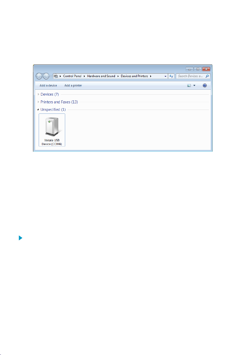
2. Open Devices and Printers from the Windowsâ Start menu. Use search to find it if
necessary (search for "devices").
41
Page 44
MHT410 User Guide M211737EN-H
3. Locate the cable in the list of devices:
• If the device is listed as Vaisala USB Device with a COM port number in brackets, the
cable is ready for use. Note the COM port number, you will need it later.
• If the device is listed as Vaisala USB Instrument Cable without a COM port number
listed, you must install the driver manually.
4. To install the driver manually:
a. Disconnect the USB service cable from the computer.
b. Download the Vaisala USB driver at http://www.vaisala.com/software (select the
appropriate USB Instrument Driver Setup for your cable).
c. Run the USB driver installation program Vaisala USB Device Driver
Setup.exe. Accept the installation defaults.
d. Go back to step 1 and verify that the driver installation works as expected.
7.1.2 Connecting USB service cable
To connect the USB service cable to the service port:
1. Make sure the USB service cable is connected to your computer.
2. Open the 4 hex screws on the cover of the transmitter using a 5-mm Allen key, and open
the cover.
3. Connect the USB service cable to the service port connector on the transmitter circuit
board.
4. Configure the terminal application settings.
7.1.3 Configuring terminal application settings
The steps below describe how to connect to the transmitter using the PuTTY terminal
application for Windows (available for download at www.vaisala.com) and a USB service cable:
42
Page 45

Chapter 7 – Vaisala Industrial Protocol
1. Make sure the USB service cable is connected to your PC and the service port of the
transmitter.
2. Start the PuTTY application.
3. Select Connection > Serial & USB and check that the correct COM port is selected in the
Serial or USB line to connect to field. If you are using the PuTTY terminal application
supplied by Vaisala, you can select USB Finder... to open the Vaisala USB Instrument
Finder program.
4. Check that the other serial settings are correct, and change if necessary.
Table 5 Service port serial interface settings
Property Value
Baud rate 19200
Parity None
Data bits 8
Stop bits 1
Flow control None
5. Select Terminal. Use the following settings:
• Local Echo: "Force on". This setting ensures that your typing is shown on the session
window.
• Send line ends with line feeds (CR+LF): Selected. This setting ensures that all text
lines remain visible on the session window.
43
Page 46

MHT410 User Guide M211737EN-H
6. Select Open to open the connection window and start using the serial line.
If PuTTY is unable to open the serial port you selected, it will show you an
error message instead. If this happens, restart PuTTY and check the settings.
7.2 Serial commands summary
The notation <cr> refers to the carriage return control character, which you can send in a
terminal application by pressing Enter on your keyboard. Before entering commands, send a
<cr> to clear the command buer.
You can enter the commands in uppercase or lowercase. In the command examples, the
keyboard input by the user is in bold type.
Table 6 Serial commands
Command Description More
Device information and status:
?
??
alarm
errlog
errs
help
system
time
vers
Serial line output and communication:
addr
Show device information. Table 7
Show device information (will respond in poll mode).
Show or set H2 alarm level. Table 8
Show error log records. Table 9
Show active errors. Table 10
Show list of serial commands. Table 11
Show firmware information. Table 12
Show transmitter uptime (time since last reset). Table 13
Show the software version information. Table 14
Show or set device address used in Modbus communication and
in Vaisala Industrial Protocol when the device is in POLL mode.
information
(page 46)
(page 47)
(page 48)
(page 49)
(page 50)
(page 50)
(page 51)
(page 51)
Table 23
(page 59)
44
Page 47

Chapter 7 – Vaisala Industrial Protocol
Command Description More
close
Close connection to device in POLL mode.
This command cannot be used via the Service Port.
form
Set output format of measurement messages. Table 19
information
Table 24
(page 60)
(page 56)
intv
Set measurement output interval. Table 15
(page 52)
log
Show measurement log records and configure logging settings. Table 16
(page 52)
open
r
Open connection to device in POLL mode.
This command cannot be used via the Service Port.
Table 25
(page 60)
Start continuous output of measurement messages. Table 17
(page 55)
sdelay
Show or set serial line transmission delay. Table 26
(page 60)
send
Output one measurement message. Table 18
(page 55)
seri
Set serial line settings for the RS-485 line of the screw terminals.
Default is 19200 N 8 1.
Table 27
(page 61)
This command does not aect the service port settings.
smode
Set serial line operation mode for the RS-485 line of the screw
terminals.
Table 28
(page 62)
This command does not aect the service port settings. The
service port is always in stop mode.
unit
Set temperature unit to metric (°C) or non-metric (°F). Table 22
(page 59)
Analog output:
aerr
Show or set error level for analog output. Table 29
(page 63)
aover
Enable or disable analog output 10 % over range. Table 30
(page 63)
asel
Show or set analog output parameters and scaling. Table 31
(page 64)
atest
Test analog outputs by forcing them to a given value. Table 32
(page 66)
Calibration and adjustment:
cdate
Show or set adjustment date. Table 33
(page 67)
45
Page 48

MHT410 User Guide M211737EN-H
Command Description More
ctext
h2 da
h2 db
h2 x
Other commands:
dnp3 addr
filt
frestore
oil
reset
h2 is
Show or set adjustment information text. Table 34
Start or continue hydrogen calibration and adjustment sequence. Table 35
Clear hydrogen calibration and adjustment data. Table 36
Change the data link address of the transmitter in DNP3
communication.
Show or set measurement filtering. Table 38
Restore factory settings. Clears all user settings, factory
calibration remains.
Show or set oil-specific coecients for moisture ppm
calculation.
Reset the device. Table 40
Initialize the device after it has been re-installed in a new location. Table 42
w
information
(page 67)
(page 68)
(page 68)
Table 37
(page 68)
(page 69)
Table 39
(page 69)
Table 41
(page 70)
(page 70)
(page 70)
7.3 Device information and status commands
Table 7 ? command
Syntax Description
?<cr> Show listing of device information.
??<cr> Show listing of device information when device is in poll mode
46
and connection has not been opened using the open command.
Page 49

Syntax Description
Example:
?
MHT410 / 0.1.20
Serial number : L2110001
Batch number : L1940010
Sensor number : L102
Sensor model : Humicap L2
Order code : MHT410 1CXEO
Cal. date : 20150414
Cal. info : Vaisala
Uptime : 0000d 04:04:41
Total time : 0000d 04:04:41
Serial mode : STOP
Baud P D S : 19200 N 8 1
Output interval : 1 S
Serial delay : 25
Address : 0
Filter : 1.000
Ch1 output : 4 ... 20 mA
Ch2 output : 4 ... 20 mA
Ch3 output : 4 ... 20 mA
Ch1 RS lo : 0.00 %
Ch1 RS hi : 100.00 %
Ch2 T lo : -40.00 'C
Ch2 T hi : 100.00 'C
Ch3 H2 lo : 0.00 ppm
Ch3 H2 hi : 5000.00 ppm
Chapter 7 – Vaisala Industrial Protocol
Table 8 alarm command
Syntax Description
alarm<cr> Check the status and setpoint (ppmv) of the hydrogen alarm.
The alarm is activated when the 1-hour average for hydrogen
exceeds the setpoint.
alarm [on | off]
[setpoint]<cr>
Set the hydrogen alarm status.
on = Alarm indication is on.
o = Alarm indication is o.
setpoint = Hydrogen level above which the alarm is activated.
Example (check the hydrogen alarm status, alarm is o):
alarm
Alarm display : OFF ?
Setpoint (ppm) : 300 ?
47
Page 50

MHT410 User Guide M211737EN-H
Syntax Description
Example (enable the hydrogen alarm and set the alarm limit to 200 ppmv hydrogen):
alarm on 200
Alarm display : ON
Setpoint (ppm) : 200
Table 9 errlog command
Syntax Description
errlog print<cr>
Show the error log with max. 25 last log entries.
The error log stores the error status each time the status
changes.
You can save the error log as a file from PuTTY
by configuring the following settings in PuTTY
before opening the connection:
In the Session > Logging window:
• Session logging: Select "Printable output".
• Log file name: Type a name for the log file (use
extension .txt) and browse for the location
where to save the file.
errlog print [n]
[i]<cr>
errlog save<cr>
errlog clear<cr>
48
Show the error log with a chosen number of entries.
n = Number of entries to show (max. 9999).
i = Optional: Index number of the first shown entry. If this
parameter is not used, the list will show the last n number of
entries.
Save the current error status for troubleshooting purposes.
Remove all entries from the error log.
Clearing the error log may make
troubleshooting more dicult later if a problem
occurs.
Page 51

Chapter 7 – Vaisala Industrial Protocol
Syntax Description
Example (show error log):
errlog print
index RecNum Reset Days Time ERRS H2err Y(T) Y(RH) fm_cnt
1 1 1 0 00:00:00 8 0 1.0947 4.7467 0
2 2 2 0 00:37:29 8 0 1.0984 0.5565 6
3 3 2 0 00:37:14 8 0 1.1004 2.4597 0
4 4 2 0 00:38:46 8 0 1.1027 0.5147 7
5 5 2 0 01:10:02 8 0 1.1146 2.5202 0
6 6 2 0 01:15:57 8 0 1.1156 0.5876 6
7 7 3 0 00:36:21 8 0 1.1160 -3.9274 1
Example (show the last 5 entries):
errlog print 5
index RecNum Reset Days Time ERRS H2err Y(T) Y(RH) fm_cnt
27 27 19 0 04:59:27 8 0 1.1160 -3.9274 1
28 28 19 0 05:11:40 0 0 1.1167 0.5479 6
29 29 19 0 05:18:53 8 0 0.7497 0.3019 6
30 30 19 0 05:21:12 0 0 0.2000 -0.1030 6
31 31 19 0 05:22:36 8 0 1.1187 0.5538 7
Example (save the current error status):
errlog save
New value stored.
Example (remove all entries from the error log):
errlog clear
Erase all Error Log data? (Y/N) y
Erasing...
Error Log cleared.
Table 10 errs command
Syntax Description
errs<cr>
Show currently active errors.
The possible errors and their remedies are listed in Table 46
(page 91).
49
Page 52

MHT410 User Guide M211737EN-H
Syntax Description
Example (no errors active):
errs
No errors
Example (active error):
errs
0008 H2 module communication error
H2scan message: wait
Table 11 help command
Syntax Description
help<cr>
Show a list of available commands.
Example:
help
Stop mode commands:
ADDR AERR ALARM AOVER ASEL ATEST CDATE CLOSE
CTEXT DNP3 ERRLOG ERRS FILT FORM FRESTORE H2
HELP INTV LOG R RESET SDELAY SEND SERI
SMODE SYSTEM TIME UNIT VERS ?
Poll mode commands:
OPEN SEND ??
Table 12 system command
Syntax Description
system<cr>
Show firmware information.
Example:
system
Device Name : MHT410
Copyright : Copyright (c) Vaisala Oyj 2015. All rights reserved.
SW Name : MHP410
SW date : 2015-05-05
SW version : 1.0.0
OS version : TSF 1.0
50
Page 53

Table 13 time command
Syntax Description
time [mode]<cr>
Show transmitter uptime (time since last reset). Default output:
hh:mm:ss.
mode = alternative output option (optional)
• 1 = include days (dddd hh:mm:ss)
• 2 = include decimals of seconds (hh:mm:ss.sss)
• 3 = include days and decimals of seconds
• 4 = include total operating time
Example (show transmitter uptime in hh:mm:ss):
time
Uptime : 00:50:04
Example (show transmitter uptime with days):
time 1
Uptime : 2d 01:50:39
Table 14 vers command
Syntax Description
vers<cr>
Show the software version information.
Example:
Chapter 7 – Vaisala Industrial Protocol
vers
MHT410 / 1.0.0
51
Page 54

MHT410 User Guide M211737EN-H
7.4 Serial line output and communication commands
7.4.1 Measurement output commands
Table 15 intv command
Syntax Description
intv<cr>
intv [iii uuu]<cr>
Example (set the output interval to 1 second):
intv 1 s
Output interval: 1 S
Show the output interval of the automatically repeating
measurement messages (r command and run mode).
This command has no eect on the operation of the analog
output.
Set the output interval.
iii = interval, range 1 ... 255
uuu = unit for interval setting:
• s = seconds
• min = minutes
• h = hours
Table 16 log command
Syntax Description
log print<cr>
52
Show the measurement log with max. 100 last log entries.
You can save the log as a file from PuTTY by
configuring the following settings in PuTTY
before opening the connection:
In the Session > Logging window:
• Session logging: Select "Printable output".
• Log file name: Type a name for the log file (use
extension .txt) and browse for the location
where to save the file.
To prevent the log from getting very long,
consider saving and then clearing the log every
few years.
Page 55

Syntax Description
log print [n] [i]<cr>
Show the measurement log with a chosen number of entries.
n = Number of entries to show (max. 32767).
i = Optional: Index number of the first shown entry. If this
parameter is not used, the list will show the last n number of
entries.
log alarm [on|off]<cr>
Enable or disable storing a log item when the H2 concentration (1
hour average) exceeds the alarm level. Logging continues once
an hour until the H2 level returns below the alarm limit or until
alarm logging is disabled. The log entries contain the additional
tag "H2alarm".
You set the H2 alarm level using the alarm command (see Table
8 (page 47)).
log filt [on|off]<cr>
Enable or disable the filtering of measurement values in the log.
on = For each parameter, the 24 h average value is stored. The
log entries contain the additional tag "F".
off = For H2, 1 h average is stored. For RS and T, instant values
are stored.
log save<cr>
Save the current measurement values in the log. The log entry
contains the additional tag "Tst".
log clear<cr>
log intv
[interval]<cr>
Remove all entries from the measurement log.
Set the logging interval in minutes (range: 15 ... 1440). The default
interval is 720 minutes (12 hours).
Example (show up to 100 last entries in the log):
Chapter 7 – Vaisala Industrial Protocol
log print
index Reset Days Uptime Total Time RS(%) H2O(ppm) Temp('C) H2(ppm) Flags
1 2 0 00:08:23 0 00:17 10.000 13.900 45.406 18.0 N Tst
2 2 0 00:13:02 0 00:22 10.000 13.900 45.467 18.0 N Tst
3 5 0 00:37:17 0 00:59 10.000 13.900 45.303 18.0 N Tst
4 5 0 00:52:54 0 01:14 10.000 13.900 45.278 18.0 N Tst
5 7 0 12:00:43 0 13:14 10.000 13.900 45.887 18.0 N
6 11 0 00:04:31 0 13:18 10.000 13.900 45.495 18.0 N
7 11 0 00:12:08 0 13:26 10.000 12.900 45.716 18.1 N
8 12 0 00:03:15 0 13:29 10.000 13.900 45.531 18.2 N
Example (show the last 5 entries):
log print 5
index Reset Days Uptime Total Time RS(%) H2O(ppm) Temp('C) H2(ppm) Flags
4 5 0 00:52:05 0 01:14 10.000 13.900 45.278 18.0 N Tst
5 7 0 12:00:24 0 13:14 10.000 13.900 45.887 18.0 N
6 11 0 00:04:41 0 13:18 10.000 13.900 45.495 18.0 N
7 11 0 00:12:16 0 13:26 10.000 12.900 45.716 18.1 N
8 12 0 00:03:43 0 13:29 10.000 13.900 45.531 18.2 N
53
Page 56

MHT410 User Guide M211737EN-H
Syntax Description
Example (show 5 entries starting from the 3rd entry):
log print 5 3
index Reset Days Uptime Total Time RS(%) H2O(ppm) Temp('C) H2(ppm) Flags
3 5 0 00:37:23 0 00:59 10.000 13.900 45.303 18.0 N Tst
4 5 0 00:52:31 0 01:14 10.000 13.900 45.278 18.0 N Tst
5 7 0 12:00:12 0 13:14 10.000 13.900 45.887 18.0 N
6 11 0 00:04:57 0 13:18 10.000 13.900 45.495 18.0 N
7 11 0 00:12:48 0 13:26 10.000 12.900 45.716 18.1 N
Example (enable storing a log item when H2 alarm level is exceeded):
log alarm on
Alarm loggings: OFF -> ON
Example (disable filtering the measurement values in the log):
log filt off
24h rolling average filter: ON -> OFF
Measurement log column information
Column Description
index
Reset
Days
Uptime
Total Time
RS (%)
H2O (ppm)
Temp (ºC)
H2 (ppm)
Flags
Log record number (1 to 32767)
Reset count
Number of days since last reset (uptime)
Hours, minutes, and seconds of uptime
Total operating time (days, hours, minutes)
H2O relative saturation in oil
H2O concentration, absolute (ppm by weight)
Oil temperature
Hydrogen concentration in oil (ppm by volume)
See flag descriptions below.
Log entry type indicators in Flags column
ID Description
N
H2alarm
Log item stored every 12 hours (or at selected rate)
H2 value (1 hour average) has exceeded alarm limit
54
Page 57

Chapter 7 – Vaisala Industrial Protocol
Syntax Description
RESET
Power-on or reset has occurred. In a RESET log entry, the H2
(ppm) column shows the reset cause, and measurement
columns show dashes (-.---) instead of measurement
information.
UPS
Tst
F
*ERR*
**CRC ERR**
Power down detected, UPS is running
The log item was saved using log save command
Filter was on when the log record was saved
Error was active when the log record was saved
Checksum error in the log record
Table 17 r command
Syntax Description
r<cr>
Start the continuous outputting of measurement values as an
ASCII text string to the serial line.
The transmitter keeps outputting measurement messages at the
interval that has been set with the intv command until stopped
with the s command.
Example:
r
T= 45.1 'C RS= 10.0 % H2O= 13.9 ppm aw= 0.100 H2= 17 ppm
T= 45.0 'C RS= 10.0 % H2O= 13.9 ppm aw= 0.100 H2= 17 ppm
T= 45.0 'C RS= 10.0 % H2O= 13.9 ppm aw= 0.100 H2= 17 ppm
T= 45.1 'C RS= 10.0 % H2O= 13.9 ppm aw= 0.100 H2= 17 ppm
T= 45.1 'C RS= 10.0 % H2O= 13.9 ppm aw= 0.100 H2= 18 ppm
T= 45.1 'C RS= 10.0 % H2O= 13.9 ppm aw= 0.100 H2= 18 ppm
T= 45.1 'C RS= 10.0 % H2O= 13.9 ppm aw= 0.100 H2= 18 ppm
T= 45.2 'C RS= 10.0 % H2O= 13.9 ppm aw= 0.100 H2= 18 ppm
...
Table 18 send command
Syntax Description
send<cr>
Output a single measurement message. The output uses the
format defined with the form command.
send [yyy]<cr>
Output a single measurement message when the transmitter is in
poll mode and connection has not been opened using the open
command.
yyy = Address of the transmitter, range 0 ... 255. The address is
set with the addr command.
55
Page 58

MHT410 User Guide M211737EN-H
Syntax Description
send ROC<cr>
Output the rate-of-change readings for H2 and H2O (daily, weekly
and monthly ROC for each parameter).
send a<cr>
Output a single measurement message with the following
parameters:
• T
• RS
• aw
• H2O
• H
2
Example (transmitter in stop mode, no address needed):
send
T= 45.1 'C RS= 10.0 % H2O= 13.9 ppm aw= 0.100 H2= 17 ppm
Example (transmitter in poll mode, with address 10):
send 10
T= 45.1 'C RS= 10.0 % H2O= 13.9 ppm aw= 0.100 H2= 17 ppm
Example (transmitter in stop mode, output rate-of-change readings):
> send roc
ROCs: 61 H2: 0.7 1.6 3.7 H2O: -0.362 1.262 2.458
>
7.4.2 Measurement output format commands
Table 19 form command
Syntax Description
form<cr>
form /<cr>
form [sss]<cr>
56
Show the currently used measurement format.
Reset measurement format to default.
Set a new measurement format.
sss = String consisting of modifiers and abbreviations for
measured parameters.
See Table 20 (page 57) and Table 21 (page 58).
Maximum length is 150 characters. Maximum length may be
shorter when text strings are used.
Page 59

Chapter 7 – Vaisala Industrial Protocol
Syntax Description
Example (show currently used measurement format, default format shown here):
form
3.1 "T=" t " " U3 3.1 "RS=" rs " " U4 6.1 "H2O=" h2o " " U5 4.3 "aw=" aw " "
6.0 "H2=" h2 " " U5 \r \n
Output example (continuous output in RUN mode):
T= 45.0 'C RS= 10.0 % H2O= 13.9 ppm aw= 0.100 H2= 18 ppm
Example (change the order of the output to show H2 first, with Modulus-65536 checksum at the
end):
form 6.0 "H2=" h2 " " U5 3.1 "T=" t " " U3 3.1 "RS=" rs " " U4 6.1 "H2O=" h2o
" " U5 4.3 "aw=" aw " " cs4 #r #n
OK
Output example (continuous output in RUN mode):
H2= 18 ppm T= 45.0 'C RS= 10.0 % H2O= 13.9 ppm aw= 0.1 0E22
Example (show H2O in ppmw without decimals, with start of text (ASCII character 002) and end of
text (003) ASCII codes, and without line feed and carriage return at the end):
form #002 6.0 "H2=" h2 " " U5 3.1 "T=" t " " U3 3.1 "RS=" rs " " U4
6.0 "H2O=" h2o " " U5 4.3 "aw=" aw " " #003
OK
Output example (continuous output in RUN mode):
H2= 18 ppm T= 45.0 'C RS= 10.0 % H2O= 14 ppm aw= 0.100
Table 20 Output parameters for form command
Measurement parameter Abbreviation in form command
Relative saturation of water in oil, %RS
Water activity in oil, aw (range 0.0 ... 1.0)
Water content in oil, ppm
w
Water content in oil, ppmw. 24 hour average.
H2O daily ROC, ppmw.
H2O weekly ROC, ppmw.
H2O monthly ROC, ppmw.
rs
aw
h2o
h2oa
h2od
h2ow
h2om
57
Page 60

MHT410 User Guide M211737EN-H
Measurement parameter Abbreviation in form command
Hydrogen content in oil, ppmv. One hour average.
Hydrogen content in oil, ppmv. 24 hour average.
H2 daily ROC, ppmv.
H2 weekly ROC, ppmv.
H2 monthly ROC, ppmv.
Oil temperature, °C or °F
h2
h2a
h2d
h2w
h2m
t
Table 21 Modifiers for form command
Modifier Description
x.y
#t
#r
#n
" "
#xxx
Length modifier (number of digits and decimal places).
Tabulator.
Carriage-return.
Line feed.
String constant, length 1 ... 15 characters.
ASCII code value (decimal) of a special character; for example,
#027 for ESC.
addr
date
err
sn
time
ux
Transmitter address (0 ... 254).
Uptime in days.
Error code, ASCII encoded hexadecimal notation.
Transmitter serial number.
Uptime (hh:mm:ss).
Name of the measurement unit using x number of characters
(1 ... 9). For example, u3 shows the name of the measurement
unit with three characters.
cs2
Modulus-256 checksum of message sent so far, ASCII encoded
hexadecimal notation.
cs4
Modulus-65536 checksum of message sent so far, ASCII encoded
hexadecimal notation.
csx
NMEA xor-checksum of message sent so far, ASCII encoded
hexadecimal notation.
58
Page 61

Chapter 7 – Vaisala Industrial Protocol
You can also use the backslash character \ instead of the hash character #.
Table 22 unit command
Syntax Description
unit<cr>
Show the current temperature unit system (metric °C or nonmetric °F).
unit [m|n]<cr>
Change the temperature unit.
m = Metric unit, °C
n = Non-metric unit, °F
Example (show current unit and check the output):
unit
Units : Metric
send
T= 45.0 'C RS= 10.0 % H2O= 13.9 ppm aw= 0.100 H2= 18 ppm
Example (change temperature unit from °C to °F and check the output):
unit n
Units : Non metric
send
T=113.0 'F RS= 10.0 % H2O= 13.9 ppm aw= 0.100 H2= 18 ppm
7.4.3 Serial line communication commands
Table 23 addr command
Syntax Description
addr<cr>
addr [aaa]<cr>
Show current device address and prompt for a new address. This
device address is used in Modbus communication, and in Vaisala
Industrial Protocol communication in POLL mode.
The transmitter's data link address for DNP3
communication is configured with the dnp
addr3 command, see Table 37 (page 68).
Set new device address.
aaa = address, 0 ... 255
59
Page 62

MHT410 User Guide M211737EN-H
Syntax Description
Example (shows 0 as current address, enter 5 as the new address):
addr
Address : 0 ? 5
Table 24 close command
Syntax Description
close<cr>
Close the connection that was opened with the open command.
This command cannot be used via the service port.
Example:
close
line closed
Table 25 open command
Syntax Description
open [aaa]
Connect to a transmitter that is in poll mode.
aaa = transmitter address, 0 ... 255
If you do not know the address of the transmitter, use the ??
command to view the transmitter information.
This command cannot be used via the service port.
Example (target transmitter in poll mode, with address 5):
open 5
MHT410 5 line opened for operator commands
Table 26 sdelay command
Syntax Description
sdelay<cr>
sdelay [delay]<cr>
Show serial line transmission delay.
Set a new serial line transmission delay.
delay = 0 ... 255. Value corresponds to four milliseconds (for
example, 5 = 0.020 second transmission delay)
Note that setting a too short delay may result in missing
characters at the beginning of the transmission (requirements
vary depending on use case).
60
Page 63

Syntax Description
Example (set serial delay to 0.1 seconds using the delay value 25):
sdelay 25
Serial delay : 25
Table 27 seri command
Syntax Description
seri<cr>
Show current serial line settings for the RS-485 line of the screw
terminals.
This command does not aect the service port settings.
seri [p b d s] <cr>
Set new serial line settings. The new settings will be taken into
use when the transmitter is reset or powered up.
b = baud rate (300, 600, 1200, 2400, 4800, 9600, 19200, 38400,
57600)
p = parity
• n = none
• e = even
• o = odd
d = data bits (7 or 8)
s = stop bits (1 or 2)
For Modbus, baud rate must be 9600 ... 57600 and parity must
be none.
Example (show current settings):
Chapter 7 – Vaisala Industrial Protocol
seri
Baud P D S : 19200 N 8 1
Example (set baud rate to 9600, and reset the transmitter take the new baud rate in use):
seri 9600 N 8 1
Baud P D S : 9600 N 8 1
reset
MHT410 / 1.2.0
61
Page 64

MHT410 User Guide M211737EN-H
Table 28 smode command
Syntax Description
smode<cr>
Show current start-up operating mode for the RS-485 line of the
screw terminals, and prompt to enter new mode.
This command does not aect the service port settings. The
service port is always in stop mode.
smode [mode]<cr>
Set the start-up operating mode for the RS-485 line of the screw
terminals. The new mode is taken into use when the transmitter is
reset or powered up.
This command does not aect the service port settings. The
service port is always in stop mode.
Available modes:
modbus = Default mode. Modbus protocol is used for
communication on the RS-485 line of the screw terminals,
including measurement output. See Overview of Modbus
protocol support (page 39).
dnp3 = DNP3 protocol. See DNP3 protocol (page 71).
stop = Vaisala Industrial Protocol: no automatic output. All
commands available.
run = Vaisala Industrial Protocol: automatic output of
measurement messages. You can stop the output with the s
command, and recontinue with the r command.
poll = Vaisala Industrial Protocol: no automatic output. Will
respond to addressed send [aaa] command and ??
command. You can use other commands after opening a
connection using an addressed open [aaa] command. Use the
poll mode with RS-485 buses where multiple transmitters can
share the same line.
Example (check current serial operating mode (default setting with Modbus mode in use)):
smode
Serial mode : MODBUS
Example (set serial operating mode to poll, and reset the transmitter to start up in that mode):
smode poll
Serial mode : POLL
reset
MHT410 / 1.2.0
62
Page 65

7.5 Analog output commands
Table 29 aerr command
Syntax Description
aerr<cr>
aerr [ch1 ch2 ch3]<cr>
Example (show current error levels, default levels shown here):
aerr
Ch1 error out : 3.500 mA ?
Ch2 error out : 3.500 mA ?
Ch3 error out : 3.500 mA ?
Example (set the error level to 21 mA on all channels):
aerr 21 21 21
Ch1 error out : 21.000 mA
Ch2 error out : 21.000 mA
Ch3 error out : 21.000 mA
Show error levels for the analog outputs channel by channel and
prompt to enter a new value.
Set new error levels for analog outputs.
ch1 = Error level of the analog output for channel 1.
ch2 = Error level of the analog output for channel 2.
ch3 = Error level of the analog output for channel 3.
When you set new error levels, make sure they are outside the
scaled output range 4 ... 20 mA (or 4.0 ... 21.6 mA if aover
extension is on, see Table 30 (page 63)).
Chapter 7 – Vaisala Industrial Protocol
Table 30 aover command
Syntax Description
aover<cr>
Check whether the high end of the analog outputs is extended by
10 percent of the range (from 20 mA to 21.6 mA).
aover [off|on]<cr>
Enable or disable the analog output overrange extension.
off = The range of the analog outputs is 4 ... 20 mA.
on = The range of the analog outputs is 4 ... 21.6 mA. The scaling
of the outputs is not aected.
63
Page 66

20 mA
21.6 mA
4 mA
Low end
of scale
High end
of scale
High end
of scale
+10 %
of scale
Analog output
Analog output extended at high end of range
CURRENT
OUTPUT
MEASURED
VALUE
MHT410 User Guide M211737EN-H
Syntax Description
Example (check whether the analog output range is extended (extension is o), and enable the
extension):
aover
AOVER : OFF
aover on
AOVER : ON
For example, channel 3 outputs temperature with output 4 ... 20 mA (-40 ... 100 °C). After giving
the aover on command, the range is 4 ... 21.6 mA (-40 ... 124 °C). Note that the 100 °C point is still
at 20 mA.
Figure 5 Analog output overrange behavior
Table 31 asel command
Syntax Description
asel<cr>
Show analog output parameters and scaling and prompt to enter
new scaling.
asel ?<cr>
Show analog output parameters and scaling without prompting
to enter new scaling.
64
Page 67

Chapter 7 – Vaisala Industrial Protocol
Syntax Description
asel [ch1 ch2 ch3]
[ch1low ch1high ch2low
ch2high ch3low
ch3high]<cr>
Set analog output parameters and scaling.
ch1 = Output parameter for channel 1.
• rs = relative saturation of water, %RS
• aw = water activity (range 0.0 ... 1.0)
• h2o = H2O concentration in oil, ppm
• h2 = H2 concentration in oil, ppm
w
v
• t = temperature, °C
• h2oa = H2O concentration in oil (24 h average), ppm
• h2od = H2O daily ROC, ppm
• h2ow = H2O weekly ROC, ppm
• h2om = H2O monthly ROC, ppm
w
w
w
• h2a = H2 concentration in oil (24 h average), ppm
• h2d = H2 daily ROC, ppm
• h2w = H2 weekly ROC, ppm
• h2m = H2 monthly, ppm
v
v
v
w
v
ch2 = Output parameter for channel 2. The options are the same
as for channel 1.
ch3 = Output parameter for channel 3. The options are the same
as for channel 1.
Optional:
ch1low = Low limit for channel 1 output scaling.
ch1high = High limit for channel 1 output scaling.
ch2low = Low limit for channel 2 output scaling.
ch2high = High limit for channel 2 output scaling.
ch3low = Low limit for channel 3 output scaling.
ch3high = High limit for channel 3 output scaling.
The default scaling of H2O and H2 ROC readings is as follows:
• H2O daily, weekly, and monthly ROC: -50 ... 50 ppm
• H2 daily, weekly, and monthly ROC: -500 ... 500 ppm
w
w
Example (show current parameters and scaling for each channel and prompt to enter new scaling):
asel
Ch1 RS lo : 0.00 % ?
Ch1 RS hi : 100.00 % ?
Ch2 T lo : -40.00 'C ?
Ch2 T hi : 100.00 'C ?
Ch3 H2 lo : 0.00 ppm ?
Ch3 H2 hi : 5000.00 ppm ?
65
Page 68

MHT410 User Guide M211737EN-H
Syntax Description
Example (show current parameters and scaling for each channel without prompting to enter new
scaling):
> asel ?
Ch1 RS lo : 0.00 %
Ch1 RS hi : 100.00 %
Ch2 T lo : -40.00 'C
Ch2 T hi : 100.00 'C
Ch3 H2 lo : 0.00 ppm
Ch3 H2 hi : 5000.00 ppm
Example (change channel 1 to output water activity, adjust scaling to 0 ... 1 for channel 1, and to
0 ... 2000 ppmv for channel 3):
asel aw t h2 0 1 -40 100 0 2000
Ch1 aw lo : 0.00
Ch1 aw hi : 1.00
Ch2 T lo : -40.00 'C
Ch2 T hi : 100.00 'C
Ch3 H2 lo : 0.00 ppm
Ch3 H2 hi : 2000.00 ppm
Example (change channel 3 to output H2 weekly ROC):
asel aw t h2w
Ch1 aw lo : 0.00 ?
Ch1 aw hi : 1.00 ?
Ch2 T lo : -40.00 'C ?
Ch2 T hi : 100.00 'C ?
Ch3 H2W lo : -500.00 ppm ?
Ch3 H2W hi : 500.00 ppm ?
If you change the output parameters, the scaling for each channel is set to
default and you are prompted to enter new low and high limits for each channel.
If you do not want to change one of more of the default limits, press Enter at
those prompts.
Table 32 atest command
Syntax Description
atest [ch1 ch2 ch3]
Set analog channel to defined output value (in mA).
You can then measure the output with a calibrated multimeter.
ch1 = Output level for channel 1 in mA.
ch2 = Output level for channel 2 in mA.
ch3 = Output level for channel 3 in mA.
66
Page 69

Chapter 7 – Vaisala Industrial Protocol
Syntax Description
Example (enable analog output test mode, set level to 20 mA on all channels):
atest 20 20 20
Analog output test mode: ON
CH1: 20.000 mA
CH2: 20.000 mA
CH3: 20.000 mA
Example (disable analog output test mode, resume normal output):
atest
Analog output test mode: OFF
CH1: 7.568 mA
CH2: 13.714 mA
CH3: 4.038 mA
7.6 Calibration and adjustment commands
Table 33 cdate command
Syntax Description
cdate<cr>
cdate [yyyymmdd]<cr>
Example (show current calibration date):
Show the date of the last adjustment.
Set a new calibration and adjustment date (format "yyyymmdd").
cdate
Cal. date : 20150201
Example (set new calibration date):
cdate 20150630
Cal. date : 20150630
Table 34 ctext command
Syntax Description
ctext<cr>
ctext [text]<cr>
Show adjustment information text.
Set a new calibration and adjustment information text.
67
Page 70

MHT410 User Guide M211737EN-H
Syntax Description
Example (show current calibration text):
ctext
Cal. info : Vaisala
Example (set new calibration text):
ctext H2 cal DGA lab sample
Cal. info : H2 cal DGA lab sample
Table 35 h2 da and h2 db commands
Syntax Description
See H 2 calibration and
adjustment (page 85).
Calibrate and adjust H2 measurement. When you start the
adjustment, normal measurement stops temporarily and the
transmitter goes into error state. Measurement returns to normal
when you exit the H2 adjustment mode.
After the adjustment, set the adjustment date and information
using the cdate and ctext commands.
Table 36 h2 x command
Syntax Description
See Clearing H 2 calibration
and adjustment (page 88)
Clears the H2 calibration and adjustment data. Removes the
adjustment applied with the h2 da and h2 db commands and
restores the factory calibration. This adjustment will take eect
immediately and is applied to all future H2 readings.
7.7 Other commands
Table 37 dnp3 addr command
Syntax Description
dnp3 addr [aaa]<cr>
See DNP3 protocol (page 71) and Taking DNP3 protocol into use (page 71).
68
Change the data link address of the transmitter in DNP3
communication.
aaa = Data link address of the transmitter
Page 71

Chapter 7 – Vaisala Industrial Protocol
Table 38 filt command
Syntax Description
filt [f.fff]<cr>
Set the speed at which the latest moisture and temperature
measurement (approximately one measurement per second) is
integrated into readings.
The command aects both analog output and serial line output.
This command does not aect the H2 reading.
f.fff = Measurement filtering factor setting, range 0.001 ... 1.0.
The default value is 1.0 (no filtering).
When filtering is used, the output is calculated based on the
following formula:
output = [(new (unfiltered) measurement × filtering factor) +
(previous output × (1.0 - filtering factor))]
With filtering factor value 1 the transmitter takes only the latest
measurement into account, but with filtering factor value 0.1 the
new output is a combination of previous measurements (90%)
and the latest measurement (10%).
Filtering factor value examples:
• 1.0 = No filtering, the latest measurement is output directly
without integrating previous measurements.
• 0.5 = The reading output shows ~75% of the measurement
change after two one-second measurement cycles and ~93%
after four cycles.
• 0.1 = The reading output shows ~90% of the measurement
change after 22 measurements.
filt<cr>
Shows the current setting and prompts for a new value.
Example (view the current value and set filtering factor value to 0.5):
filt
Filter : 1.000 ? 0.5
Table 39 frestore command
Syntax Description
frestore<cr>
Restore factory settings. Clears all user settings, including serial
communication settings, transmitter address, and analog output
configurations.
H2 calibration remains.
Example:
frestore
Factory settings restored
69
Page 72

MHT410 User Guide M211737EN-H
Table 40 reset command
Syntax Description
reset<cr>
Reset the transmitter. The transmitter will restart as if it had just
been powered on.
Example:
reset
MHT410 / 1.0.0
Table 41 oil command
Syntax Description
oil<cr>
View oil-specific parameters (oil coecients A and B) for
moisture ppmw calculation. Leave current values in place by
pressing <cr> at the prompt.
See Moisture ppm w calculation for transformer oils (page 113).
oil<cr>
Set oil-specific parameters for moisture ppmw calculation by
entering oil coecients A (Oil[0]) and B (Oil[1]) when
prompted.
Example:
oil
Oil[0] : -1662.6999 ?
Oil[1] : 7.3694 ?
Table 42 h2 is command
Syntax Description
See Re-installing the
transmitter in new location
Initialize the device after it has been re-installed in a new
location.
(page 35).
70
Page 73

Chapter 8 – DNP3 protocol
8. DNP3 protocol
MHT410 can be used as a DNP3 outstation (starting from software version 1.2.0). It supports
serial communication only. Serial communication is based on RS-485 hardware, and therefore
MHT410 can be used in multidrop topology.
The MHT410 device profile files for DNP3 are available for download at www.vaisala.com/
mht410.
DNP3 protocol is available from the RS-485 line of the MHT410 screw terminals, which can
support only one protocol at a time (DNP3, Modbus, or Vaisala Industrial Protocol). The factory
default protocol is Modbus. To take DNP3 to use, you must change the communication
protocol and other DNP3-related settings via the MHT410 service port, using Vaisala Industrial
Protocol commands.
Table 43 Default communication settings
Setting Factory default Options
Communication protocol Modbus DNP3, Modbus, Vaisala Industrial
Communication
parameters
Data link address 4 0 … 32767
Host address 3 0 … 32767
Baud rate: 19200
Parity: None
Number of data bits: 8
Number of stop bits: 1
Protocol
Baud rate: 300, 600, 1200, 4800, 9600,
19200, 38400, 57600
Parity: None
Number of data bits: 8
Number of stop bits: 1, 2
More information
‣
Connecting to MHT410 via service port (page 41)
8.1
Taking DNP3 protocol into use
1. To active the DNP3 communication mode, type smode dnp3 in the terminal window and
press Enter.
Example:
smode dnp3
Serial mode : DNP3
71
Page 74

MHT410 User Guide M211737EN-H
2. Optional: To change the baud rate or number of stop bits, type seri [baud rate] N
8 [number or stop bits] and press Enter.
• Baud rate options: 300, 600, 1200, 4800, 9600, 19200 (default), 38400, 57600
• Stop bit number options: 1 (default), 2
Example (set baud rate to "38400" and number of stop bits to "2"):
seri 38400 N 8 2
Baud P D S : 38400 N 8 2
Do not change the other communication parameters: parity ("N") or number
of data bits ("8"). If you change these settings, DNP3 communication will not
work on MHT410.
3. Optional: To change the data link address (default: 4), type dnp3 addr [data link
address] and press Enter.
Data link address range: 0 ... 32767
Example (change data link address to "10"):
dnp3 addr 10
DNP3 ADDR : 4 -> 10
DNP3 HOST : 3
The DNP HOST setting is currently not used. The current implementation of
the DNP3 protocol on MHT410 only sends responses to the host that sends a
request.
4. To save the settings, reset the transmitter by typing reset and pressing Enter.
reset
MHT410 / 1.2.0
5. Close the PuTTY terminal application.
6. Disconnect the USB cable from the service port, and close the transmitter cover.
72
Page 75

6
5
4
3
2
1
Chapter 9 – Vaisala MI70 Handheld Indicator
9. Vaisala MI70 Handheld Indicator
You can use the MI70 handheld indicator as a temporary display for the transmitter.
MI70 shows the readings for all the parameters measured by the transmitter. You can also view
the trend of the measurement on the graphical display, and compare the moisture and
temperature readings of MHT410 to a Vaisala MM70 reference probe.
The MI70 indicator is intended to be used as display only. You cannot use MI70 to
configure and calibrate MHT410.
To configure the transmitter, use Vaisala Industrial Protocol (see Vaisala Industrial
Protocol (page 40)). For H2 calibration instructions, see H 2 calibration and
adjustment (page 85).
9.1 MI70 indicator overview
9.1.1 MI70 indicator parts
Figure 6 MI70 indicator parts
1 Charger socket
2 Function key shortcut buttons . The
functions change according to what
you are doing with the indicator.
3 Arrow buttons:
Move up in a menu
Move down in a menu
Enter a sub-menu
Return to previous menu level
4 Power On/O button
5 Battery compartment at the back of
the indicator
6 2 ports (labeled I and II) for
connecting probes and instruments.
To open menus, press an arrow button and then press the shortcut buttons. To activate a
function shown above the shortcut button, press the shortcut button. To navigate in the
menus, press the arrow buttons.
73
Page 76

1
3 4 5
2
2
1
5
3
4
MHT410 User Guide M211737EN-H
9.1.2 Basic display
Figure 7 MI70 basic display
1 Measured parameter and compensations (up to three items on display simultaneously).
You can change the shown items in Main menu > Display > Quantities and units.
2 Battery indicator. Shows current status (charge) of the battery.
3 Function key Graphic shows the readings as a curve.
4 Function key Hold/Save freezes the display and you can save the reading in the MI70
memory.
5 Function key Record is a quick access to the Recording/Viewing menu.
You can change the default function key shortcuts (Graphic, Hold/Save, Record) to other
menus or functions in Main menu > Settings > User interface > Program shortcut keys.
9.1.3 Graphical display
The graphical display shows you the measurements as a curve (the curve of the uppermost
parameter shown in the basic display). From the curve you can examine the data trend and
history of the last minutes.
To open the graphical display, select Graphic in the basic display or select Main menu >
Display > Graphic history > Show.
To get the statistical info on the graph area (minimum, maximum, and average values), press
Info.
To get the curve of the other selected parameters, press Next. To get the curves of all the
parameters, press Next until the text All appears, and then select All.
To zoom in and out, press the up/down arrow buttons.
To move back and forward in the timeline, use the left/right arrow buttons.
74
Page 77

Chapter 9 – Vaisala MI70 Handheld Indicator
9.1.4 Main menu
To open the main menu:
1. Go to the basic display.
2. Press any arrow key, then select OPEN.
In the main menu, you can configure the MI70 settings and basic display. You can also perform
certain operations with the transmitter.
More information
‣
Holding and saving the display (page 76)
‣
Recording data (page 77)
‣
Comparing readings with MM70 probe (page 78)
9.2
Installing and recharging MI70 batteries
If you are using alkaline batteries, unscrew the back plate of the indicator and insert the
batteries. Do not attempt to recharge standard alkaline batteries.
If you ordered MI70 with a rechargeable battery, it is already in place as shipped from the
factory. The delivered batteries have been pre-charged.
To recharge the rechargeable battery:
1. Plug in the charger connector to the MI70 indicator. The socket is located at the top of the
indicator, covered by a rubber seal.
2. Connect the charger to a wall socket. An animated battery icon in the left corner of the
display indicates that the battery is charging. The recharge duration (typically 4 ... 5 h)
depends on the charge level of the battery.
A new battery takes approximately 3 charging cycles to reach its maximum
capacity.
Do not store the batteries empty. Empty batteries may not charge after an
extended storage period.
75
Page 78

MHT410 User Guide M211737EN-H
9.3 Connecting MI70 to service port
• MI70 indicator or MM70 meter (includes MI70 indicator, a moisture-in-oil
probe, and a ball valve)
• Connection cable (Vaisala item code 219980)
• Power supply for MHT410
1. Open the screws on the transmitter cover, and open the cover.
2. Connect cable 219980 to the service port connector on the transmitter and to port I or II
of the MI70 indicator.
3. Switch the MI70 indicator on.
9.4 Holding and saving the display
With the Hold/Save function, you can freeze a certain display reading. This reading can be
saved in the MI70 memory and it will be available even after MI70 is disconnected from the
transmitter.
1. In the basic display, select Hold/Save. Alternatively, select Main menu > Display > Hold/
Save display > Hold.
2. Press Save.
3. To view the saved display, go to basic display and select Record > View recorded data.
Alternatively, select Main menu > Recording/Viewing > View recorded data.
A list of saved displays and data recordings appears. The icons on the left of the date and
time indicate whether the file is a saved display or a longer recording of data:
Saved display
Data recording
4. Select the saved display based on date and time by pressing the right arrow button.
76
Page 79

Chapter 9 – Vaisala MI70 Handheld Indicator
9.5 Recording data
With MI70, you can record transmitter measurement data over a certain period at chosen
intervals. These recordings are saved in the MI70 memory and are available even after MI70 is
disconnected from the transmitter. To start recording, select the Record function key in the
basic display, or navigate to the recording menu: Main menu > Recording/Viewing > Record
data.
9.5.1 Starting and stopping the recording
You can record the measurement of the parameters that are currently shown on the MI70 basic
display. You can change the shown parameters in Main menu > Display > Quantities and units.
1. In the basic display, select Record > Record data. Alternatively, select Main menu >
Recording/Viewing > Record data.
2. If needed, change the interval and duration of the recording in the RECORD DATA view.
The measurement intervals and maximum recording times are shown in the following
table.
Recording interval
1 s 45 min 22 min 15 min
5 s 3 h 113 min 75 min
15 s 11 h 5 h 3 h
30 s 22 h 11 h 7 h
1 min 45 h 22 h 15 h
5 min 9 days 4 days 3 days
15 min 28 days 14 days 9 days
30 min 56 days 28 days 18 days
1 h 113 days 56 days 37 days
3 h 339 days 169 days 112 days
12 h 1359 days 678 days 451 days
Maximum recording time (= memory full)
1 parameter 2 parameters 3 parameters
If you set the duration to "Memory full", the recording continues until the
MI70 memory is full or until you stop the recording manually. The maximum
recording time is shown when you start the recording.
77
Page 80

MHT410 User Guide M211737EN-H
3. Select Start/Stop recording > Start.
The recording continues until the duration has passed or until you stop the recording
manually.
You can switch the MI70 o during recording to save battery. A progress bar is
shown on the display every 10 seconds (or all the time, if a charger is connected). The
progress bar shows the amount of recorded data.
CAUTION!
even if the indicator is o. This may cause loss of recorded data.
4. To stop the recording manually, in the basic display select Record > Record data > Start/
stop recording > Stop. To view the recorded file, select Show.
Do not disconnect the probe when the data recording is on,
9.5.2 Viewing recorded data
1. Open the menu by pressing Open.
2. Select Recording/Viewing and press .
3. Select View recorded data and press .
4. Select the file you want to view and press . The files are identified according to the
starting date and time of recording.
5. To go to the graphical view, press Graph. To view the recording time stamps, press
Times. To return to the recording values, press Values.
6. To return to the basic display, press Exit.
9.5.3 Clearing data memory
1. Open the menu by pressing Open.
2. Select Recording/Viewing and press .
3. Select Clear data memory and press Clear. To confirm the deletion, press Yes.
4. To return to the basic display, press
Exit.
9.6
Comparing readings with MM70 probe
• Vaisala HUMICAPâ Handheld Moisture Meter for Oil MM70
You can use MI70 to compare the measurement readings of MHT410 to an MM70 reference
probe.
78
Page 81

Chapter 9 – Vaisala MI70 Handheld Indicator
The indicator shows the readings from both devices at the same time. You can also show the
dierence in reading for water activity (Δaw) and temperature (ΔT).
1. Install the MM70 probe in the same transformer as MHT410. For instructions, see the
MM70 User's Guide (available at www.vaisala.com/mm70).
2. Turn o the MI70 indicator.
3. If MHT410 is not connected to MI70, connect it to one of the MI70 ports (I or II).
4. Connect the MM70 probe to the other MI70 port.
5. Turn on MI70.
The basic display now shows the readings from both devices. The port of the device is
indicated next to the measured parameter. You can change the shown parameters in Main
menu > Display > Quantities and units.
Figure 8 Example of MI70 display with MHT410 in port I and MM70 probe in port II. Shown
parameters: aw (I), aw (II), Δ aw.
9.7
Changing the rechargeable battery pack
• New rechargeable battery pack
• Medium-sized flat head screwdriver
In case you are installing a rechargeable battery pack in the MI70 indicator and you have a
device with alkaline batteries, remove the metal contact from the probe port end of the
battery compartment before installing the battery pack.
1. Open the back plate of the indicator by opening the screw of the back plate.
2. Remove the old battery pack. Detach the black connector by carefully pulling it up from
the wires.
79
Page 82

MHT410 User Guide M211737EN-H
3. Connect the black connector of the new battery pack. Make sure the position of the
connector is as shown in the following figure (red and black wires are on the upper edge
of the connector). Do not push the connector with conducting material.
4. Place the battery pack in the compartment.
5. Close the back plate and tighten the screw.
6. Recharge the indicator before use.
80
Page 83

Chapter 10 – Vaisala Indigo520 Transmitter
10. Vaisala Indigo520 Transmitter
Starting from MHT410 software version 1.3.0, the MHT410 transmitter can be connected to an
Indigo520 transmitter for powering and communication. The Indigo520 transmitter can act as
a local display for MHT410, and also provide its measurements as analog output signals or as
Modbus protocol messages.
The Indigo520 connection is available from the RS-485 line of the MHT410 screw terminals.
The connection through the screw terminals can support only one protocol at a time (DNP3,
Modbus, or Vaisala Industrial Protocol). An MHT410 connected to Indigo520 cannot be
connected to another host system via its own serial line. However, the analog signals in the
MHT410 remain available.
For instructions on connecting a computer to MHT410 to change the MHT410 communication
settings, see Connecting to MHT410 via service port (page 41).
Table 44 MHT410 communication settings for Indigo520
Setting Factory default Valid for Indigo520 use
Communication protocol Modbus Modbus
Communication parameters Baud rate: 19200
Parity: None
Number of data bits: 8
Number of stop bits: 1
Baud rate: 19200
Parity: None
Number of data bits: 8
Number of stop bits: 2
10.1 Taking Indigo520 Modbus settings into use in MHT410
1. To activate the Modbus communication mode, type smode modbus in the terminal
window and press Enter.
Example:
smode modbus
Serial mode : MODBUS
2. To change the baud rate or number of stop bits, type seri 19200 N 8 2 and press
Enter.
Example:
seri 19200 N 8 2
Baud P D S : 19200 N 8 2
81
Page 84

ANALOG OUTPUTS
RELAY 1RELAY 2
+
+
+
+
+
+
+
+
+
CH1
CH2
CH3
CH4
RS-485
PROBE
24 VOUT
ANALOG
INPUT
NO COM NC NO COM NC
1
2
VS
+
1
MHT410 1 B E G 4
1
MHT410 User Guide M211737EN-H
3. To save the settings, reset the transmitter by typing reset and pressing Enter.
reset
MHT410 / 1.x.x
4. Close the PuTTY terminal application.
5. Disconnect the USB cable from the service port, and close the transmitter cover.
10.2 Cabling and cable gland
Vaisala oers a 10-meter (33-feet) cable for connecting MHT410 to Indigo520 (Vaisala item
code CBL210968-10MSP). In Indigo520, the cable is designed to be inserted through the
default M16×1.5 cable gland of probe 1. The recommended maximum length of the probe cable
is 30 m (98 ft).
1 Indigo520 probe 1 lead-through,
M16×1.5
In MHT410, the correct M20×1.5 cable gland must be used for a secure connection. You can
check the size of the factory-installed cable gland from the 5th character of the order code in
the MHT410 product label.
If the 5th character is 4, this means that MHT410 has the M20×1.5 cable gland compatible with
cable CBL210968-10MSP. If not, the right cable gland is available as a spare part (Vaisala item
code ASM213670SP).
If you are using a custom cable between MHT410 and Indigo520, make sure that:
82
MHT410 order code example. The 5th
1
character indicates the size of the
cable gland.
Page 85

ANALOG OUTPUTS
RELAY 1RELAY 2
+
+
+
+
+
+
+
+
+
CH1
CH2
CH3
CH4
RS-485
PROBE
24 VOUT
ANALOG
INPUT
NO COM NC NO COM NC
1
2
VS
+
9 10 11 12 13 14 15 16
D-
D+
+V
s
-V
s
SHLD
SHLD
RS-485
POWER
RS
GND
Indigo520 MHT410
Chapter 10 – Vaisala Indigo520 Transmitter
• The cable is maximum 30 m (98 ft) in length
• The cable has enough free wires to fulfill the wiring diagram as per Figure 9 (page 83).
Any excess wires should be properly isolated.
• The cable diameter is compatible with the cable glands installed in both MHT410 and
Indigo520
• The cable is shielded.
Whether you are using the Vaisala cable CBL210968-10MSP or a custom cable, see Electrical
installation (page 28) on how to install the cable and connect shielding in MHT410.
10.3 Indigo520 and MHT410 wiring diagram
Figure 9 Wiring between Indigo520 and MHT410 screw terminals
Indigo520 screw terminal
MHT410 screw terminal Wire color in Vaisala cable
Probe 1, 24 VOUT+ VS+ Pink
Probe 1, 24 VOUT− VS− Brown
Probe 1, RS-485+ D+ Green
Probe 1, RS-485− D− Yellow
Probe 1, 24 VOUT− RS GND
Not connected Not connected Gray
1) Shown in the figure above with a dashed line.
CBL210968-10MSP
1)
White
83
Page 86

MHT410 User Guide M211737EN-H
10.4 MHT410 status messages shown in Indigo520
Table 45 MHT410 status messages shown in Indigo520
Error Description Recommended action
Firmware checksum
mismatch
Ambient temperature
out of range
Humidity
measurement error
Temperature
measurement error
Hydrogen
measurement error
Firmware is corrupted Reboot MHT410. Wait for the status LED to turn
Measured temperature
is outside the error
limits (below −45 or
above +125 °C (below
−49 or above
+257 °F)).
Readings from the
humidity sensor are
missing or out of
range.
Temperature
measurement raw
value is outside the
allowed range.
H2 module has
reported an error.
solid green, and check the operation of the
transmitter.
Contact Vaisala technical support.
Ensure that the operating temperature is within
the valid range −40 … +120 °C (−40 … +248 °F).
Contact Vaisala technical support.
Reboot MHT410. Wait for the status LED to turn
solid green, and check the operation of the
transmitter.
Contact Vaisala technical support.
In case of constant error, please contact Vaisala. For contact information, see Technical
support (page 115).
10.5
Settings in Indigo520
The available interfaces in the Indigo520 transmitter depend on the configuration of the
device. For changing the Indigo520 settings, see Indigo520 User Guide (M212287EN).
84
Page 87

Chapter 11 – Calibration and adjustment
11. Calibration and adjustment
MHT410 is fully calibrated and adjusted as shipped from the factory.
11.1 H2 calibration and adjustment
You can calibrate MHT410 for H2 by comparing the H2 reading on the MHT410 to the H
concentration of a laboratory-analyzed DGA oil sample. There is no need to remove the
transmitter from the transformer to perform calibration and adjustment.
In the calibration procedure, you take a DGA oil sample from the transformer and save the H
concentration measured by the transmitter at that time. When you have analyzed the H
concentration of the sample, you enter the analyzed H2 reading to MHT410. The transmitter
then implements the adjustment to the H2 measurement.
More information
‣
Calibration and adjustment commands (page 67)
‣
Taking DGA sample and saving current H2 reading (page 85)
‣
Entering DGA H2 reading to transmitter (page 87)
‣
Clearing H2 calibration and adjustment (page 88)
2
2
11.1.1 Taking DGA sample and saving current H2 reading
• Tools for taking a DGA oil sample
• Connection to the transmitter using Vaisala Industrial Protocol in one of the
following ways:
• Service port (see Connecting to MHT410 via service port (page 41))
• RS-485 line of the screw terminals (User Port is configured for Modbus by
default: to enable command entry, connect to the transmitter via Service
Port and switch the operating mode of the screw terminals (see Table 28
(page 62)))
In the following instructions, the keyboard input by the user is in bold type.
2
When you start the H2 adjustment mode with the h2 command, normal
measurement stops temporarily and the transmitter goes into error state.
Measurement returns to normal when you exit the H2 adjustment mode.
1. Take the DGA oil sample from the transformer.
85
Page 88

MHT410 User Guide M211737EN-H
2. Open the connection on Vaisala Industrial Protocol (see Connecting to MHT410 via service
port (page 41)).
3. Start the adjustment mode with the command h2. The transmitter starts outputting H
2
measurement data.
h2
SSN=b11.04rt.10432tn1x, FW=3.85F , MDN=104400-FF02-P1, DF=0xB4B4v,
L.
..
4. Stop the output by pressing the Esc key:
...
7997.00 34.0852 50.11176 186.69 2654140 2652818 23
0.0 0 22.2649 0 0 wait
<"ESC key">
H2scan:
5. Save the H2 reading with the da command:
H2scan: da
Current H2 value is 14.4 ppm...wait...
6. When the H2 measurement output resumes, exit the adjustment mode by pressing the
+ key:
...
79842.00 33.8725 50.11766 186.97 2654214 2652858 359
14.4 0 28.5654 200 200 wait <"+ key">
Quit hydrogen measurement module command line operation
Do not exit the adjustment mode before the H2 measurement output has
resumed.
If the H2 output does not resume automatically, issue the command g and
the command v to start the H2 output, and then exit the adjustment mode.
86
Page 89

Chapter 11 – Calibration and adjustment
11.1.2 Entering DGA H2 reading to transmitter
• Connection to the transmitter using Vaisala Industrial Protocol in one of the
following ways:
• Service port (see Connecting to MHT410 via service port (page 41))
• RS-485 line of the screw terminals (User Port is configured for Modbus by
default: to enable command entry, connect to the transmitter via Service
Port and switch the operating mode of the screw terminals (see Table 28
(page 62)))
When you start the H2 adjustment mode with the h2 command, normal
measurement stops temporarily and the transmitter goes into error state.
Measurement returns to normal when you exit the H2 adjustment mode.
1. Open the connection on Vaisala Industrial Protocol (see Connecting to MHT410 via service
port (page 41)).
2. Start the adjustment mode with the command h2. The transmitter starts outputting H
measurement data.
h2
SSN=b11.04rt.10432tn1x, FW=3.85F , MDN=104400-FF02-P1, DF=0xB4B4v,
L
...
2
3. Stop the output by pressing the Esc key:
...
7997.00 34.0852 50.11176 186.69 2654140 2652818 23
0.0 0 22.2649 0 0 wait
<"ESC key">
H2scan:
4. Enter the DGA H2 reading with the db command:
H2scan: db
Enter actual hydrogen in ppm: 10
Set hydrogen to 10.0ppm (Y/N)? y
Enter Today's Date:
Month: 4
Day: 14
Year: 2015
...wait...
87
Page 90

MHT410 User Guide M211737EN-H
5. When the H2 measurement output resumes, exit the adjustment mode by pressing the
+ key:
...
79842.00 33.8725 50.11766 186.97 2654214 2652858 359
10.0 10 28.5654 200 200 wait <"+ key">
Quit hydrogen measurement module command line operation
Do not exit the adjustment mode before the H2 measurement output has
resumed.
If the H2 output does not resume automatically, issue the command g and
the command v to start the H2 output, and then exit the adjustment mode.
6. Enter the calibration date and information using the cdate and ctext commands. For
example:
cdate 20150630
Cal. date : 20150630
ctext H2 cal DGA lab sample
Cal. info : H2 cal DGA lab sample
11.1.3 Clearing H2 calibration and adjustment
• Connection to the transmitter using Vaisala Industrial Protocol in one of the
following ways:
• Service port (see Connecting to MHT410 via service port (page 41))
• RS-485 line of the screw terminals (User Port is configured for Modbus by
default: to enable command entry, connect to the transmitter via Service
Port and switch the operating mode of the screw terminals (see Table 28
(page 62))
When you start the H2 adjustment mode with the h2 command, normal
measurement stops temporarily and the transmitter goes into error state.
Measurement returns to normal when you exit the H2 adjustment mode.
1. Open the connection on Vaisala Industrial Protocol (see Connecting to MHT410 via service
port (page 41)).
88
Page 91

Chapter 11 – Calibration and adjustment
2. Start the adjustment mode with the command h2. The transmitter starts outputting H
measurement data.
h2
SSN=b11.04rt.10432tn1x, FW=3.85F , MDN=104400-FF02-P1, DF=0xB4B4v,
L
...
3. Stop the output by pressing the Esc key:
...
7997.00 34.0852 50.11176 186.69 2654140 2652818 23
0.0 0 22.2649 0 0 wait
<"ESC key">
H2scan:
4. Clear the hydrogen calibration data and adjustments with the x command.
The command removes the adjustment applied with the h2 da and h2 db commands
and restores the factory calibration. This adjustment will take eect immediately and is
applied to all future hydrogen readings.
H2scan: x
Clear dissolved gas offset values (Y/N)? y
...wait...Done.
5. When the H2 measurement output resumes, exit the adjustment mode by pressing the
+ key:
...
79842.00 33.8725 50.11766 186.97 2654214 2652858 359
10.0 10 28.5654 200 200 wait <"+ key">
Quit hydrogen measurement module command line operation
2
Do not exit the adjustment mode before the H2 measurement output has
resumed.
If the H2 output does not resume automatically, issue the command g and
the command v to start the H2 output, and then exit the adjustment mode.
11.2 RS & T calibration and adjustment
MHT410 is calibrated at the factory for RS and T. In normal transformer conditions, the
moisture in oil sensor is very stable and regular RS and T calibration is not needed. Moisture in
oil can be checked, for example, when taking an oil laboratory sample, or when checking with
a handheld indicator.
89
Page 92

MHT410 User Guide M211737EN-H
The reference oil sample should be taken near the MHT410 in order to get a sample that
matches the measurement conditions of the MHT410 sensor. The same also applies to
handheld reference checks. If changes are suspected, MHT410 can be sent to Vaisala for RS
and T calibration.
For more information on the calibration and adjustment services provided by Vaisala, visit the
Vaisala calibration website at www.vaisala.com/calibration.
When installing the handheld reference probe inside the transformer, it may take
up to 24 hours for the moisture readings to stabilize. An insucient stabilization
time may lead to incorrect results. To get the best results with handheld
measurements, always make them under flowing conditions when possible.
90
Page 93

Chapter 12 – Troubleshooting
12. Troubleshooting
12.1 Error states
MHT410 has the following states that indicate a problem with the transmitter:
• Error indication on analog outputs at 3.5 mA (default):
• With hydrogen measurement errors, the hydrogen channel is in error state.
• With moisture in oil measurement errors, the moisture in oil channel is in error state.
• With temperature measurement errors, the temperature and moisture in oil channels
are in error state.
• With general errors, all three channels are in error state.
• Error messages on the serial line:
• Modbus statuses (see Table 63 (page 111))
• Vaisala Industrial Protocol error list
In case of constant error, please contact Vaisala. For contact information, see Technical
support (page 115).
Table 46 Possible error messages via Vaisala Industrial Protocol
Error number and text Description Action
0001
Temperature
measurement error
0002
Frequency measurement
error
0004
H2 measurement error
0008
H2 module
communication error
0010
RH sensor failure
0020
Temperature too high/low
Temperature measurement
raw value is outside the
allowed range.
Moisture measurement raw
value is outside the
allowed range.
H2 module has reported an
error.
No message was received
from H2 module in the last
5 seconds.
Readings from the
humidity sensor are
missing or out of range.
Measured temperature is
outside the error limits
(below −45 or above
+125 °C (below −49 or
above +257 °F)).
Reboot MHT410. Wait for the status LED
to turn solid green, and check the
operation of the transmitter.
Contact Vaisala technical support.
Ensure that the operating temperature is
within the valid range −40 … +120 °C
(−40 … +248 °F).
Contact Vaisala technical support.
91
Page 94

MHT410 User Guide M211737EN-H
Error number and text Description Action
0040
Program flash CRC error
0080
Parameter flash check sum
error
0100
INFOA check sum error
0200
SCOEFS check sum error
0400
CURRENT check sum error
0800
DEFAULT (factory) check
sum error
1000
General flash failure W/R
Internal transmitter failure. Contact Vaisala technical support.
12.2 Changing bleed screw
If oil starts flowing out from the bleed screw on the mounting nut, tighten the bleed screw. If
oil still flows out, change the bleed screw.
• New bleed screw (provided in the MHT410 installation kit)
• Medium wrench (36 mm)
• Large wrench (50 mm)
• Allen key (3 mm, provided in the MHT410 installation kit)
1. Remove the transmitter. See Removing the transmitter (page 34).
2. Remove the bleed screw from the mounting nut.
3. Clean the mounting nut of any oil.
4. Install a new bleed screw and tighten it firmly.
5. Remove the old PTFE tape from the mounting nut.
6. Re-install the transmitter. See Mechanical installation (page 21).
92
Page 95

Chapter 13 – Technical data
13. Technical data
13.1 MHT410 specifications
Table 47 MHT410 measurement performance
Property Description/Value
Hydrogen
Measurement range (in oil) 0 … 5000 ppm
Accuracy 1)
Repeatability ±10 % of reading or ±15 ppmv (whichever is
Minimum detection limit 15 ppm
Typical long-term stability 3 % of reading / year
Cross sensitivity to other gases < 2 % (CO2, C2H2, C2H4, CO)
Response time 63 % of full response: 2 h (when sensor is not in
Warm-up time 2 h, 12 h for full specification
Sensor Catalytic palladium-nickel alloy film solid-state
Moisture in oil
Measurement range (in oil) 0 … 100 %RS / aw 0 … 1
Response time (90 % of full response at +20 °C
(+68 °F) in still oil)
Sensor HUMICAPâ 180L2
Accuracy (including non-linearity, hysteresis, and repeatability):
0 … 90 %RS ±2 %RS (aw ± 0.02)
90 … 100 %RS ±3 %RS (aw ± 0.03)
Temperature
Measurement range −40 … +120 °C (−40 … +248 °F)
Accuracy at +20 °C (+68 °F) ±0.2 °C (0.36 °F)
2)
±10 % of reading or ±15 ppmv (whichever is
greater)
greater)
reference cycle)
sensor
10 min
v
v
93
Page 96

MHT410 User Guide M211737EN-H
Property Description/Value
Sensor Pt1000 RTD Class F0.1 IEC 60751
1) The accuracy specified is the accuracy during calibration against gas in oil standard. Field
performance may be aected, for example, by variation in hydrogen solubility (partition
coecients) between dierent mineral oils.
2) The accuracy specified is applicable in the oil temperature specified (−20 … +75 °C
(−4 … +167 °F)).
Table 48 MHT410 operating environment
Property Description/Value
Oil type
Selected when ordering, available options:
1)
• Mineral oil
• Natural ester oil
• Synthetic ester oil
• Silicone oil
Oil temperature −20 … +75 °C (−4 … +167 °F)
Operating temperature (electronics) −40 … +60 °C (−40 … +140 °F)
Storage temperature −40 … +60 °C (−40 … +140 °F)
Operating humidity 0 … 100 %RH, condensing
Pressure tolerance (probe, short-term) Max. 10 bara
Pressure tolerance (probe, continuous) Max. 4 bara
Temperature tolerance, sensor head −40 … +120 °C (−40 … +248 °F)
Integrated protection for short power outages > 3 s
1) Changing the oil type that MHT410 measures requires reconfiguration at Vaisala.
Table 49 MHT410 inputs and outputs
Property Description/Value
Operating voltage 15 … 30 V DC, 24 V AC (±15 %) (power supply
input is galvanically isolated)
1)
Power consumption Typical 4 W, maximum 12 W
Recommended external power supply 24 V DC / 0.5 A minimum
Analog output (current)
1)
Channels 3 isolated 4 … 20 mA (loop-powering required)
External load Max. 500 Ω
94
Page 97

Chapter 13 – Technical data
Property Description/Value
Error status indication in case of device error 3.5 mA default, user-configurable for each
channel
mA output accuracy at +20 °C (+68 F) ±0.125 % full scale
Temperature dependence of the analog outputs ±0.006 % / °C full scale
Digital outputs
1)
Interfaces Isolated RS-485 half-duplex
RS-485 (Service Port)
Protocols Modbus RTU, DNP3, serial ASCII commands
Screw terminals Wire size AWG 22-14
Single wire (solid) 1.5 mm
Stranded wire (flex.) 1.0 mm
2
2
Recommended wire torque 0.4 Nm
1) Max. isolation voltage 1.5 kV DC.
Table 50 MHT410 mechanical specifications
Property Description/Value
Mechanical connection on transmitter 1.5" NPT (male)
Cable gland (optional, for use with Indigo520) M20×1.5 for cable diameter 5 … 9 mm
(0.20 … 0.35 in)
Cable gland (optional) M20×1.5 for cable diameter 8 … 11 mm
(0.31 … 0.43 in)
Cable gland (optional) M20×1.5 for cable diameter 11 … 14.5 mm
(0.43 … 0.57 in)
Conduit fitting (optional) 1/2" NPT
Interface cable (optional, pre-assembled) 5 m (16 ft 5 in), 9.2 mm (0.36 in) outer diameter
Interface cable (optional) 10 m (33 ft), 9.2 mm (0.36 in) outer diameter
Interface cable (optional, for use with
10 m (33 ft), 6.2 mm (0.24 in) outer diameter
Indigo520)
Housing material AlSi 10 Mg
IP rating IP66: Dust-tight. Protected from powerful water
jets from any direction.
Transmitter weight without cables 4.1 kg (9.04 lb)
Self-diagnostics indication Status LEDs, analog output, Modbus
95
Page 98

MHT410 User Guide M211737EN-H
Property Description/Value
Integrated data logging capabilities Non-volatile memory, up to 44 years' storage
with default logging
Individual functional test reports Calibration test reports for moisture, hydrogen,
and temperature; probe leak test report (5 bara
nominal)
Factory warranty 5 years
Table 51 MHT410 compliance
Property Description/Value
EU directives EMC Directive (2014/30/EU)
RoHS Directive (2011/65/EU)
EMC compatibility EN 61326‑1, industrial environment
CISPR 32 / EN 55032, Class B (when DC
powered)
Compliance marks CE, EAC, RCM, WEEE
Table 52 Display with relays (external option)
Property Description/Value
Pre-configured range for hydrogen 0 … 5000 ppm
Pre-configured alarm relays (user-
reconfigurable)
Relay 1 trigger limit 200 ppmv (hi)
Relay 2 trigger limit 1500 ppmv (hihi)
v
Input 4 … 20 mA, loop-powered
Accuracy 0.05 % of span (−10 … +60 °C (−14 … +140 °F))
Relays 2 × solid state (SSR)
Max. 250 V AC, 150 mA
Display 4-digit red LED, 14.5 mm
Dimensions (H × W × D) 100 × 100 × 57 mm (3.94 × 3.94 × 2.24 in)
Case protection IP65: Dust-tight. Protected from water jets from
any direction.
Case material and color ABS plastic, grey
Cable glands 2 × M16×1.5
96
Page 99

13.2 Spare parts and accessories
Table 53 MHT410 spare parts and accessories
Item Item code
USB cable for PC connection 219690
External DIN rail power 100 … 240 V AC /
95 … 220 V DC to 24 V DC
5 m shielded PUR cable CBL210392-5MSP
10 m shielded PUR cable CBL210392-10MSP
Cable gland 214728SP
Detachable screw terminal block 236620SP
Loop-powered external display, Nokeval 302
(with alarm relays)
MI70 connection cable 219980
Conduit fitting 214780SP
1.5-inch NPT ball valve with welding fitting BALLVALVE-3SET
242422
242003
Chapter 13 – Technical data
97
Page 100

1.5” NPT
334
132
94.5
202
38.5
51 25.5
76.5
20.6
74
50
36
Cable Ø 8...11
150
125
270
222
mm
MHT410 User Guide M211737EN-H
13.3 Dimensions
Figure 10 MHT410 transmitter dimensions
98
 Loading...