

Vaisala MAWS201MP TACMET Installation Manual

TACMET Weather Station for
Pole Mast Installations
MAWS201MP
INSTALLATION
MANUAL
M210485EN-B
October 2003

PUBLISHED BY
Vaisala Oyj Phone (int.): +358 9 8949 1
P.O. Box 26 Fax: +358 9 8949 2227
FIN-00421 Helsinki
Finland
Visit our Internet pages at http://www.vaisala.com/
© Vaisala 2003
No part of this manual may be reproduced in any form or by any means,
electronic or mechanical (including photocopying), nor may its contents be
communicated to a third party without prior written permission of the copyright
holder.
The contents are subject to change without prior notice.
Please observe that this manual does not create any legally binding obligations for
Vaisala towards the customer or end user. All legally binding commitments and
agreements are included exclusively in the applicable supply contract or
Conditions of Sale.

________________________________________________________________________________
VAISALA ________________________________________________________________________ 1
Table of Contents
CHAPTER 1
GENERAL INFORMATION............................................................................9
About This Manual ................................................................... 9
Contents of This Manual ....................................................... 9
Feedback............................................................................. 10
Safety....................................................................................... 10
General Safety Considerations ........................................... 10
Product Related Safety Precautions ................................... 10
ESD Protection.................................................................... 13
Trademarks ............................................................................. 13
License Agreement ................................................................ 13
Warranty..................................................................................14
Technical Support .................................................................. 14
CHAPTER 2
PRODUCT OVERVIEW................................................................................ 15
Introduction to TACMET MAWS ........................................... 15
MAWS Operating Software.................................................... 17
Radiation Shield ..................................................................... 17
AWS Logger QML102T........................................................... 18
Power Supply and Connection Unit QMP202MP ................ 19
Backup Battery....................................................................19
Battery Regulator QBR101 .................................................19
Power Supply Unit BWC15SXZ .......................................... 19
Power Supply Unit BWT36SXZ .......................................... 20
Power Strip QPS101 ........................................................... 20
Transmitter WT501 ............................................................. 21
Modem Module DMX501 .................................................... 21
Ultrasonic Wind Sensor WS425............................................ 22
Air Temperature and Relative Humidity
Sensor QMH101M................................................................... 23
Pressure Sensor PMT16A ..................................................... 24
Rain Gauge QMR101M........................................................... 25
Ceilometer CT25KAM............................................................. 25
Present Weather Detector PWD11A ..................................... 26
Lightning Detector SA20M ....................................................27
Tiltable Pole Mast ................................................................... 28
Foundation Set.................................................................... 29
Guy Wires............................................................................ 30
Lightning Rod ...................................................................... 31
Winch .................................................................................. 31
Obstruction Light ................................................................. 32

Installation Manual _________________________________________________________________
2 ___________________________________________________________________ M210485EN-B
Workstation with MIDAS IV Software ...................................33
Communication Accessory Enclosure QCA101..................34
Handheld Terminal QMD101M............................................... 34
Radio Modem ..........................................................................35
VHF Antennas .....................................................................36
UHF Antennas ..................................................................... 37
Mains Power Supply Module QMP211 ...............................38
Product Nomenclature ...........................................................39
CHAPTER 3
INSTALLATION OF THE MAST ..................................................................41
Siting Criteria ..........................................................................41
Soil Evaluation..................................................................... 41
Wind Measurement .............................................................42
Air Temperature and Relative Humidity ..............................43
Precipitation.........................................................................43
Lightning Detection.............................................................. 44
Present Weather Detection ................................................. 45
Cloud Detection ................................................................... 47
Site Preparation ......................................................................47
Power Supply and Communication Lines ...........................47
Required Tools .......................................................................48
Unpacking Instructions for the Mast ....................................48
Inspection of the Delivery ....................................................48
Contents of the Delivery ......................................................48
Foundation ..............................................................................51
Soil and Frost Conditions .................................................... 51
Orientation of the Mast ........................................................51
Concrete Foundation Types ................................................ 54
Making a New Concrete Pad .........................................56
Using an Existing Concrete Pad ....................................59
Assembling the Mast..............................................................60
Work Order .......................................................................... 60
Installing the Pedestal Tube ................................................ 61
Connecting the Lowest Mast Tube to the
Pedestal Tube .....................................................................63
Connecting the Lifting Rod to the Mast ...............................64
Connecting the Guy Wire Set to the Mast...........................65
Assembling the Mast Tubes ................................................ 66
Assembling the Lightning Rod.............................................67
Connecting the Grounding Cable to the Insulated
Guy Wire..............................................................................68
Routing the Device Cables..................................................69
Erecting the Mast.................................................................... 70
Installing and Using the Winch ............................................ 70
Securing the Hinge..............................................................73
Connecting the Guy Wires to the Concrete Pads ...............74
Equipment Grounding and Lightning Protection................ 77
Equipment Grounding .........................................................80
Grounding of the Lightning Rod ..........................................83
Tilting the Mast .......................................................................84

________________________________________________________________________________
VAISALA ________________________________________________________________________ 3
Disconnecting and Securing the Guy Wire ......................... 84
Using the Winch .................................................................. 84
CHAPTER 4
INSTALLATION OF THE WEATHER STATION COMPONENTS TO
THE MAST................................................................................................... 87
Preparing Installation............................................................. 87
Unpacking Instructions .........................................................87
Weather Station Structure..................................................... 88
Mounting the Radiation Shield ............................................ 89
Mounting the Logger Tube.................................................. 90
Mounting the QMP202MP Unit ...........................................91
Mounting the Obstruction Light ........................................... 92
Installing Sensors .................................................................. 93
Mounting QMA102M Sensor Arm ....................................... 94
Mounting Ultrasonic Wind Sensor....................................... 94
Mounting the Sensor Arm ................................................... 99
Mounting Present Weather Sensor................................... 100
Mounting the Lightning Detector ....................................... 101
Mounting the Ceilometer ................................................... 103
Connecting the Cables ........................................................106
Connecting Sensors to QMP202MP ................................. 107
Connecting Sensors to the Logger Tube .......................... 108
Connecting Logger Tube to QMP202MP.......................... 108
Connecting AC Power to QMP202MP .............................. 108
Connecting the Grounding Cable to QMP202MP............. 109
Connecting Communication Cable to QMP202MP........... 109
Securing and Protecting the Cables ..................................110
Storing the Tools for Future Use ........................................ 111
Connecting and Placing the Handheld Terminal to
the Logger Tube ................................................................... 111
Installations inside QMP202MP .......................................... 111
Installing Optional Radio Communication......................... 112
Mounting the Antenna to the Mast .................................... 112
Configuring the Radio Modems ........................................ 114
Setting Up the Radio Modems ..................................... 115
Selecting the Active Channel ....................................... 119
Radio Modem Outdoors.......................................... 119
Radio Modem Indoors............................................. 119
Installing a Radio Modem to the Sensor Arm ...................120
Verification............................................................................ 122
Ceilometer CT25KAM ....................................................... 122
Lightning Detector SA20M ................................................ 123
WT501 Equipped with DMX501........................................ 123
Radio Modem.................................................................... 123
CHAPTER 5
INSTALLING INDOOR COMPONENTS.................................................... 125
Installing MIDAS IV Software ..............................................125
System Requirements....................................................... 125
Installation Procedure ....................................................... 126

Installation Manual _________________________________________________________________
4 ___________________________________________________________________ M210485EN-B
MIDAS IV TACMET Configuration.......................................127
System Parameters Tab.................................................... 128
Weather View Tab.............................................................129
QCA101 Communication Module Installation....................130
Connecting the Cables to QCA101 ...................................130
AC (Mains) Power ........................................................131
Grounding..................................................................... 131
RS-232 Connection to MIDAS IV PC ........................... 131
Communication Connection to the QCA101 Unit......... 131
Installing Optional Radio Communication.........................132
CHAPTER 6
TECHNICAL DATA ....................................................................................135
Polling/Reporting Times ......................................................135
Specifications .......................................................................136
Weather Station MAWS201MP.........................................136
Logger QML102T ..............................................................137
Power Supply and Connection Unit QMP202MP.............. 138
Digital Transmitter WT501.................................................141
Modem Module DMX501...................................................142
Handheld Terminal QMD101M..........................................143
Heated Ultrasonic Wind Sensor WS425 ...........................144
Pressure Sensor PMT16A.................................................145
Air Temperature and Relative Humidity
Sensor QMH101M............................................................. 145
Rain Gauge QMR101M.....................................................145
Ceilometer CT25KAM .......................................................146
Present Weather Detector PWD11A.................................147
Lightning Detector SA20M ................................................148
Obelux Obstruction Light...................................................148
Tiltable Pole Mast .............................................................. 149
TM32 Radio Modem..........................................................151

________________________________________________________________________________
VAISALA ________________________________________________________________________ 5
List of Figures
Figure 1 TACMET MAWS System .........................................................16
Figure 2 Radiation Shield ....................................................................... 17
Figure 3 Logger QML102T ..................................................................... 18
Figure 4 Power Strip QPS101 ................................................................ 20
Figure 5 Transmitter WT501................................................................... 21
Figure 6 Modem Module DMX501.......................................................... 21
Figure 7 Ultrasonic Wind Sensor WS425............................................... 22
Figure 8 Installation Adapter for Ultrasonic Wind Sensors..................... 23
Figure 9 QMH101M with Radiation Shield ............................................. 23
Figure 10 Pressure Sensor PMT16A ....................................................... 24
Figure 11 Rain Gauge QMR101M............................................................ 25
Figure 12 Ceilometer CT25KAM .............................................................. 25
Figure 13 Present Weather Detector PWD11A........................................ 26
Figure 14 Lightning Detector SA20M .......................................................27
Figure 15 Tiltable Pole Mast DKP210AV-T .............................................. 28
Figure 16 Foundation Set for DKP206AV ................................................ 29
Figure 17 Guy Wires Set .......................................................................... 30
Figure 18 Passive Lightning Rod and the Holders ................................... 31
Figure 19 Winch........................................................................................ 31
Figure 20 Obstruction Light with the Power Cable................................... 32
Figure 21 MIDAS IV Workstation and QCA101........................................ 33
Figure 22 QMD101M Handheld Terminal ................................................ 34
Figure 23 TM32 Radio Modem................................................................. 35
Figure 24 VHF Antenna on the Tripod ..................................................... 36
Figure 25 VHF Antenna on the Mast........................................................ 36
Figure 26 UHF Antenna on the Tripod .....................................................37
Figure 27 UHF Antenna on the Mast........................................................ 37
Figure 28 Mains Power Supply Module QMP211 .................................... 38
Figure 29 Recommended Mast Location in Open Area ........................... 42
Figure 30 Recommended Mast Length on Top of a Building................... 43
Figure 31 SA20M Vertical Obstruction (Side View).................................. 44
Figure 32 SA20M Horizontal Obstruction (Top View) ..............................45
Figure 33 Recommended Location of the PWD11A ................................46
Figure 34 Contents of the Mast Delivery (Part 1) ..................................... 49
Figure 35 Contents of the Mast Delivery (Part 2) ..................................... 50
Figure 36 DKP210AV-T Mast Orientation ................................................52
Figure 37 DKP206AV-T Mast Orientation ................................................53
Figure 38 Concrete Pad for the Mast and Orientation Plate
(Dimensions in mm) ................................................................. 54
Figure 39 Concrete Pad for Guy Wires (Dimensions in mm) ................... 55
Figure 40 Reinforcement for the Concrete Pads...................................... 56
Figure 41 Foundation Assembly for the Mast Base .................................57
Figure 42 Foundation Assemblies for a New Concrete Pad .................... 58
Figure 43 Accessories for Existing Concrete pad Installation .................. 59
Figure 44 Pedestal Tube Alignment to North-South Direction ................. 61
Figure 45 Pedestal Tube Attachment....................................................... 61
Figure 46 Pedestal Tube Adjustment with Water Level ...........................62
Figure 47 Axle for Hinge........................................................................... 63
Figure 48 Hinge Axle Installation.............................................................. 63
Figure 49 Lifting Rod Installation Accessories ......................................... 64
Figure 50 Lifting Rod Clamp Attachment ................................................. 65
Figure 51 Guy Wire Attachment ............................................................... 66

Installation Manual _________________________________________________________________
6 ___________________________________________________________________ M210485EN-B
Figure 52 Alignment of the Mast Tubes.................................................... 66
Figure 53 Lightning Rod Installation to the Mast ......................................67
Figure 54 Dimensions (in mm) for Lightning Rod Assembly
on the Mast ............................................................................... 68
Figure 55 Lightning Rod Cable Attachment.............................................. 69
Figure 56 Winch Installation .....................................................................70
Figure 57 Securing the Clamp of the Winch............................................. 71
Figure 58 Lower Cable Lead ....................................................................71
Figure 59 Attaching the Spring Clip .......................................................... 72
Figure 60 Bolts and Washers for Securing the Hinge ..............................73
Figure 61 Guy Wires ................................................................................. 74
Figure 62 Connecting the U-bolt to the Eye Bolt ......................................75
Figure 63 Guy Wire 1 Attachment ............................................................75
Figure 64 Securing the Guy Wires............................................................76
Figure 65 Installing Cable Shrouds...........................................................77
Figure 66 Location of the Grounding Rods and an Optional Grid,
the Arrow Points to the Mast Tilt Direction ...............................78
Figure 67 Ground Rod Installation............................................................80
Figure 68 Installing the Grounding Bar ..................................................... 81
Figure 69 Connecting the Grounding Cables to the Bar........................... 82
Figure 70 Grounding Cable Protection .....................................................82
Figure 71 Grounding of the Lightning Rod................................................83
Figure 72 Tilted Mast with Tilting Support ................................................85
Figure 73 Mechanical Structure of MAWS201MP ....................................88
Figure 74 Mounting the Radiation Shield..................................................89
Figure 75 Installing the Mounting Piece to the Logger Tube.................... 91
Figure 76 Mounting the Logger Tube .......................................................91
Figure 77 Mounting the Bolt and Washer for Power Supply Unit .............92
Figure 78 Mounting the Obstruction Light.................................................93
Figure 79 Mounting the Sensor Arm to the Logger Tube .........................94
Figure 80 Installing Ultrasonic Wind Sensor.............................................95
Figure 81 A Sketch of Magnetic Declination.............................................96
Figure 82 Correctly Aligned Ultrasonic Wind Sensor ...............................97
Figure 83 Ultrasonic Wind Sensor Mounted to the Mast .......................... 98
Figure 84 Sensor Arm Installation to the Mast .........................................99
Figure 85 Installing Present Weather Sensor.........................................100
Figure 86 Mounting Lightning Detector...................................................101
Figure 87 Connecting the Data Cable ....................................................102
Figure 88 Connecting the Grounding Cable ...........................................102
Figure 89 Lightning Detector Installed Facing Magnetic North ..............103
Figure 90 Installing the Ceilometer Support ...........................................104
Figure 91 Installing the Ceilometer to the Support .................................105
Figure 92 Connectors on the CT25KAM Ceilometer ..............................105
Figure 93 CT25KAM Installed on the Ceilometer Support .....................106
Figure 94 Connectors on the QMP202MP Unit ......................................106
Figure 95 Connectors on the Logger Tube............................................. 107
Figure 96 Securing Cables to the Mast ..................................................110
Figure 97 Protecting Cables with Spiral..................................................110
Figure 98 Connecting the Handheld Terminal........................................111
Figure 99 VHF Antenna Mounted on the Mast ....................................... 112
Figure 100 UHF Antenna Assembly .........................................................113
Figure 101 UHF Antenna Mounted on the Mast.......................................114
Figure 102 Connecting a Radio Modem to a PC for Configuration ..........116
Figure 103 Model Information Window ..................................................... 117
Figure 104 Radio Modem Settings ...........................................................117

________________________________________________________________________________
VAISALA ________________________________________________________________________ 7
Figure 105 Configuring Channel Frequencies.......................................... 118
Figure 106 List of the Active Channels..................................................... 120
Figure 107 Installing a Radio Modem to Sensor Arm............................... 121
Figure 108 Connecting the Data/Power Cable between
a Radio Modem and Logger Tube ......................................... 121
Figure 109 Connecting the Antenna Cable ..............................................122
Figure 110 Configuration Wizard.............................................................. 127
Figure 111 Weather View Tab.................................................................. 129
Figure 112 Connectors on the Back of the QCA101 Unit ........................ 130
Figure 113 VHF Antenna in Tripod........................................................... 132
Figure 114 UHF Antenna in Tripod........................................................... 133
Figure 115 Connecting the Radio Modem to PC...................................... 133
List of Tables
Table 1 TACMET MAWS201MP Nomenclature ................................... 39
Table 2 Cables Provided ....................................................................... 40
Table 3 Examples of Soil Resistivities, Ohm-Meters ............................ 79
Table 4 Sensors, Cables, and the Connectors on QMP202MP.......... 107
Table 5 Sensors, Cables, and the Connectors on QME101M ............ 108
Table 6 Radio Modem Settings........................................................... 118
Table 7 States of the Status LED in CT25KAM .................................. 122
Table 8 Minimum System Requirements ............................................ 125
Table 9 Explanation of Configuration Wizard Buttons ........................ 128
Table 10 Explanation of System Parameters Tab: General Frame ...... 128
Table 11 Explanation of System Parameters Tab: METAR Frame ...... 129
Table 12 Sensor Polling/Reporting Times............................................. 135
Table 13 MAWS201MP Specifications ................................................. 136
Table 14 QML102T Specifications ........................................................ 137
Table 15 Battery Regulator QBR101 Specifications
(Inside QMP202MP)............................................................... 138
Table 16 Power Supply Unit BWT36SXZ Specifications
(Inside QMP202MP)............................................................... 139
Table 17 Power Supply Unit BWC15SXZ Specifications
(Inside QMP202MP)............................................................... 140
Table 18 12 Ah Backup Battery Specifications ..................................... 140
Table 19 WT501 Specifications............................................................. 141
Table 20 DMX501 Specifications .......................................................... 142
Table 21 QMD101M Specifications....................................................... 143
Table 22 WS425 Specifications ............................................................144
Table 23 PMT16A Specifications .......................................................... 145
Table 24 QMH101M Specifications....................................................... 145
Table 25 QMR101M Specifications....................................................... 145
Table 26 CT25KAM Specifications........................................................ 146
Table 27 PWD11A Present Weather Detector Specifications .............. 147
Table 28 SA20M Specifications ............................................................ 148
Table 29 Obelux Obstruction Light Specifications ................................ 148
Table 30 DKP210AV-T Specifications .................................................. 149
Table 31 DKP206AV-T Specifications .................................................. 150
Table 32 TM32 Radio Modem Specifications ....................................... 151

Installation Manual _________________________________________________________________
8 ___________________________________________________________________ M210485EN-B
This page intentionally left blank.

Chapter 1 ________________________________________________________ General Information
VAISALA ________________________________________________________________________ 9
CHAPTER 1
GENERAL INFORMATION
This chapter provides general notes for the product.
About This Manual
This manual provides information on installing TACMET Weather
Station for Pole Mast Installations (later referred as MAWS201MP)
and the sensors to the mast. This manual also gives guidelines on how
to prepare foundations and install the DKP206AV-T and
DKP210AV-T masts.
Contents of This Manual
This manual consists of the following chapters:
- Chapter 1, General Information, provides general notes for the
product.
- Chapter 2, Product Overview, introduces the TACMET Weather
Station for Pole Mast Installations.
- Chapter 3, Installation of the Mast, provides instructions for
preparing the installation and selecting the site for the station. It
also contains detailed information on installing the tiltable pole
mast.
- Chapter 4, Installation of the Weather Station Components to the
Mast, provides detailed information on installing the weather
station logger and all the sensors to the mast.
- Chapter 5, Installing Indoor Components, provides you information
that is needed in installing the MIDAS IV workstation and
QCA101 Communication Accessory Enclosure indoors.

Installation Manual _________________________________________________________________
10 __________________________________________________________________ M210485EN-B
- Chapter 6, Technical Data, provides the technical data of the
TACMET Weather Station for Pole Mast Installations.
Feedback
Vaisala Customer Documentation Team welcomes your comments
and suggestions on the quality and usefulness of this publication. If
you find errors or have other suggestions for improvement, please
indicate the chapter, section, and page number. You can send
comments to us by e-mail: manuals@vaisala.com
Safety
General Safety Considerations
Throughout the manual, important safety considerations are
highlighted as follows:
WARNING
Warning alerts you to a serious hazard. If you do not read and follow
instructions very carefully at this point, there is a risk of injury or
even death.
CAUTION
Caution warns you of a potential hazard. If you do not read and
follow instructions carefully at this point, the product could be
damaged or important data could be lost.
NOTE
Note highlights important information on using the product.
Product Related Safety Precautions
The following are general safety precautions that are not related to any
specific procedures and therefore do not appear elsewhere in this
publication. They are recommended precautions that personnel must
understand and apply during many phases of installations, operations
and maintenance.

Chapter 1 ________________________________________________________ General Information
VAISALA _______________________________________________________________________ 11
WARNING
For safety reasons, do not install the mast alone.
WARNING
For safety reasons, do not install the mast when wind speed is over
7 m/s.
WARNING
Always wear a safety helmet during mast installation.
WARNING
Be careful when erecting or tilting the mast. See that there are no
power lines or other obstacles above or behind the mast.
WARNING
Secure the mast properly with guy wires to prevent it from falling.
Tighten all the adjustment screws properly.
WARNING
Be sure that there are no persons under the mast during erecting or
tilting the mast.
WARNING
When erecting the mast with the winch, do not touch the wire with
your bare hands. Do not try to guide the wire.
WARNING
To minimize shock hazard, the instrument chassis and cabinet must
be connected to an electrical ground. The power cable must either be
plugged into an approved electrical outlet or the instrument must be
carefully grounded to a low-resistance safety ground.

Installation Manual _________________________________________________________________
12 __________________________________________________________________ M210485EN-B
WARNING
Do not operate in an explosive atmosphere. Do not operate the
equipment in the presence of flammable gases or fumes. Operation of
any electrical instrument in such an environment constitutes a
definite safety hazard.
WARNING
Do not attempt internal service or adjustment unless another person,
capable of rendering first aid and resuscitation, is present.
WARNING
Do not service alone. Under no circumstances should any person
reach into parts and assemblies that are AC powered.
WARNING
Operating personnel must not remove instrument covers. Component
replacement or internal adjustments must be made by qualified
maintenance personnel. Do not replace components with the power
cable connected. Under certain conditions, dangerous voltages may
exist for some time even with the power cable disconnected. To
avoid injuries, disconnect power and discharge circuits before
touching them.
WARNING
Do not service the live system outdoors. Do not open units outdoors
when the enclosure contains line voltage levels.
CAUTION
Do not install substitute parts or modify the unit. Improper
modification can damage the product or lead to malfunction. Contact
Vaisala for repairs to ensure that safety features are maintained.
CAUTION
Be careful not to damage the sensors when tilting the mast.

Chapter 1 ________________________________________________________ General Information
VAISALA _______________________________________________________________________ 13
NOTE
Send old batteries to secondary lead smelter for recycling. Place
neutralized slurry into sealed containers and handle as applicable with
state and federal regulations. Large water-diluted spills, after
neutralization and testing, should be managed in accordance with
approved local, state, and federal requirements. Consult the state
environmental agency and/or federal EPA (Environmental Protection
Agency).
ESD Protection
Electrostatic Discharge (ESD) can cause immediate or latent damage
to electronic circuits. Vaisala products are adequately protected
against ESD for their intended use. However, it is possible to damage
the product by delivering electrostatic discharges when touching,
removing, or inserting any objects inside the equipment housing.
To make sure you are not delivering high static voltages yourself:
- Handle ESD sensitive components on a properly grounded and
protected ESD workbench. When this is not possible, ground
yourself with a wrist strap and a resistive connection cord to the
equipment chassis before touching the boards. When neither of the
above is possible, touch a conductive part of the equipment chassis
with your other hand before touching the boards.
- Always hold the boards by the edges and avoid touching the
component contacts.
Trademarks
Microsoft, Windows, Windows NT, and Windows 2000 are
registered trademarks of Microsoft Corporation in the United States
and/or other countries.
License Agreement
All rights to any software are held by Vaisala or third parties. The
customer is allowed to use the software only to the extent that is
provided by the applicable supply contract or Software License
Agreement.

Installation Manual _________________________________________________________________
14 __________________________________________________________________ M210485EN-B
Warranty
For certain products Vaisala normally gives a limited one year
warranty. Please observe that any such warranty may not be valid in
case of damage due to normal wear and tear, exceptional operating
conditions, negligent handling or installation, or unauthorized
modifications. Please see the applicable supply contract or conditions
of sale for details of the warranty for each product.
Technical Support
For technical questions, contact the Vaisala technical support:
E-mail helpdesk@vaisala.com
Telephone +358 9 8949 2789
Fax +358 9 8949 2790

Chapter 2 __________________________________________________________ Product Overview
VAISALA _______________________________________________________________________ 15
CHAPTER 2
PRODUCT OVERVIEW
This chapter introduces the TACMET Weather Station for Pole Mast
Installations.
Introduction to TACMET MAWS
TACMET MAWS is an automatic weather station designed for
permanent installation. TACMET MAWS accesses and processes data
from its sensors, performs data quality control, as well as formats data
for output in application specific formats. Figure 1 on page 16 shows
the components of the TACMET MAWS system.
The AWS logger QML102T is located in the tube and is encased to
protect the circuit board and the battery.

Installation Manual _________________________________________________________________
16 __________________________________________________________________ M210485EN-B
Figure 1 TACMET MAWS System
The following numbers refer to Figure 1 above:
1 = Heated Ultrasonic Wind Sensor
2 = Tiltable 6 m (20 ft) or 10 m (33 ft) mast
3 = Lightning Detector
4 = Power Supply and Connection Unit
5 = Ceilometer
6 = Obstruction Light
7 = Present Weather Detector
8 = Air Temperature and Relative Humidity Sensor
9 = Rain Gauge
10 = AWS Logger with Pressure Sensor
11 = Handheld Terminal
12 = MIDAS IV PC
13 = Communication Accessory Enclosure
Chapter 2 __________________________________________________________ Product Overview
VAISALA _______________________________________________________________________ 17
MAWS Operating Software
The embedded operating software runs in the AWS logger QML102T.
Access to the limited set of commands can be gained using the
Handheld Terminal QMD101M or using MIDAS IV PC.
Radiation Shield
Figure 2 Radiation Shield
The radiation shield protects the QME101M logger tube, which is the
same as with the mobile TACMET system, and the Power Supply and
Connection Unit QMP202MP.

Installation Manual _________________________________________________________________
18 __________________________________________________________________ M210485EN-B
AWS Logger QML102T
Figure 3 Logger QML102T
QML102T is a complete AWS logger designed on just one printed
board. This board contains a 32 bit Motorola CPU for data processing
and 10 differential (20 single ended) analog sensor inputs, that can
also be used as digital inputs. Moreover, there are two frequency
sensor interfaces, a 16 bit A/D converter, 1.7 Mbytes of secure Flash
memory for data logging, and a charger for the internal backup
battery.
The board uses the latest SMD (Surface Mount Device) technology
and is conformal coated for improved protection also in high
humidity. Each sensor input has a varistor (VDR) protection against
induced transients. The maintenance terminal connection (RS-232,
COM0) has transzorb diodes in its inputs.
In MAWS201MP the QML102T logger is located inside the logger
tube QME101M and is further encased to protect the circuit board and
the internal battery. The cover of this protective housing can be
removed for installation of the battery and for maintaining MAWS.
Optional modules under the housing include, for example, various
communication modules and a built-in pressure transducer.

Chapter 2 __________________________________________________________ Product Overview
VAISALA _______________________________________________________________________ 19
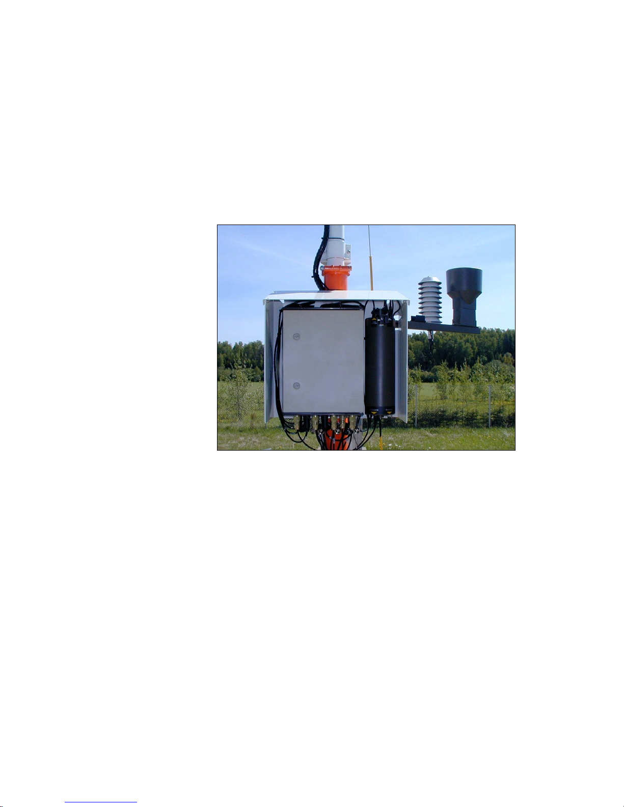
Power Supply and Connection Unit QMP202MP
MAWS201MP (see Figure 2 on page 17) is a low-power system.
When AC (mains) power (230 or 115 VAC) is available on the
installation site, an AC (mains) power supply is used to charge the
battery. QMP202MP includes the following modules: the backup
battery, the battery regulator, AC (mains) power supply units, and the
communication device. The unit is easily mounted under the radiation
shield.
Backup Battery
QMP202MP houses a sealed and maintenance-free 12 Ah battery. The
battery is charged with QBR101 Battery Regulator that is connected to
the AC (mains) power supply.
Battery Regulator QBR101
Battery Regulator QBR101 is a charging and supervising instrument
for 12/24 Volts lead acid and nickel-cadmium batteries. QBR101
allows input from AC (mains) power.
The maximum charging current can be set by the internal jumper
settings either 0.5 A, 1.0 A, 2.0 A, or 2.5 A. QBR101 is applicable to
a battery capacity of 4 to 72 Ah. Self-consumption from the battery is
very low, less than 0.2 mA.
The LED lamps indicate battery regulator conditions. In order to
maximize autonomy time, the LED lamps are activated only while
pressing the ON button. QBR101 is a rail-mountable unit allowing for
easy maintenance.
Power Supply Unit BWC15SXZ
The AC (mains) power supply unit BWC15SXZ is a switching power
supply, which operates from the universal AC input of 85 to 264 VAC
and 47 to 440 Hz. The output voltage is 15 VDC, which is used for
powering the MAWS201MP system, and as an input to the battery
regulator QBR101 for charging the backup battery. BWC15SXZ is
installed inside QMP202MP on a standard DIN-rail enabling easy
maintenance of the unit.

Installation Manual _________________________________________________________________
20 __________________________________________________________________ M210485EN-B
Power Supply Unit BWT36SXZ
The AC (Mains) power supply unit BWT36SXZ is a switching power
supply, which operates from the universal AC input of 85 to 264 VAC
and 47 to 440 Hz. The output voltage is 36 VDC, which is used for
supplying heating power to Vaisala Ultrasonic Wind Sensor WS425.
BWT36SXZ is installed inside QMP202MP on a standard DIN-rail
enabling easy maintenance of the unit.
Power Strip QPS101
Figure 4 Power Strip QPS101
Power Strip QPS101 is a safety switch, which is used in connecting
the QMP202MP to AC (mains) power outlet. QPS101 has two
buttons: the test button for the circuit breaker and the current switch.
The circuit breaker activates when the leakage is over 30 mA.

Chapter 2 __________________________________________________________ Product Overview
VAISALA _______________________________________________________________________ 21
Transmitter WT501
Figure 5 Transmitter WT501
The WT501 composes the digital transmitter PCB with connectors
enclosed into an anodized aluminum profile with DIN-rail mounting.
The unit is installed as such in an equipment enclosure designed to
withstand the environmental conditions in question.
The data is provided via the onboard opto-isolated serial interface of
the transmitter unit. For long distance communication in
MAWS201MP, the transmitter is equipped with an isolated Modem
Module DMX501.
Modem Module DMX501
Figure 6 Modem Module DMX501
The DMX501 module is used for providing a long distance fixed-line
connection between MAWS201MP and MIDAS IV PC, which has an
RS-232 serial connection to a similar module installed inside the
QCA101 unit.

Installation Manual _________________________________________________________________
22 __________________________________________________________________ M210485EN-B
Through this module, MAWS201MP sends reports and data or the
MIDAS IV PC sends new settings to the logger. The modem module
DMX501 is configured at the factory to use the communication
standard V.22, 1200 bps DPSK
Ultrasonic Wind Sensor WS425
Figure 7 Ultrasonic Wind Sensor WS425
Ultrasonic Wind Sensor WS425 uses ultrasound to determine wind
speed and wind direction. The sensor has no moving parts and it is
resistant to corrosion and contamination The sensor has a built-in
heater. The elements have a built-in thermostat to switch the heaters
on when the transducer head needs it. The sensor needs 36 VDC to
power the heater elements. When connected to MAWS201MP, the
sensor uses the analog signal output providing wind speed and
direction data.
An adapter for the Ultrasonic Wind Sensor is included in the mast
delivery. It has a clamp for mast attachment and two holes for sensor
attachment. See Figure 8 on page 23.

Chapter 2 __________________________________________________________ Product Overview
VAISALA _______________________________________________________________________ 23
Figure 8 Installation Adapter for Ultrasonic Wind Sensors
Air Temperature and Relative Humidity Sensor
QMH101M
Figure 9 QMH101M with Radiation Shield
Air Temperature and Relative Humidity Sensor QMH101 is based on
Vaisala's field-proven HMP45D probe and comes with a special cable
and connector. For humidity measurements, the HUMICAP® sensor
is highly accurate and offers excellent long-term stability in a wide
range of environments. Temperature measurements are taken by an
accurate Pt-100 IEC751, 1/3 Class B.
Replacement is simple; the probe head containing the electronics can
be quickly removed from the probe body, while a replacement is

Installation Manual _________________________________________________________________
24 __________________________________________________________________ M210485EN-B
installed and the measurement continues. Meanwhile the other probe
head can be calibrated.
The probe is installed in a naturally aspirated shield made of injection
molded UV stabilized plastic. The shield has a multiplate design
providing the necessary shielding from solar radiation and
precipitation.
Pressure Sensor PMT16A
Figure 10 Pressure Sensor PMT16A
The silicon capacitive pressure sensor PMT16A has excellent
accuracy, repeatability, and long-term stability over a wide range of
operating temperatures. It maintains its accuracy and calibration for
long periods of time, thus reducing the need for field calibrations.
The fine adjustment and calibration of the sensor at the factory are
handled according to the electronic working standards, which are
based on international standards.
Chapter 2 __________________________________________________________ Product Overview
VAISALA _______________________________________________________________________ 25
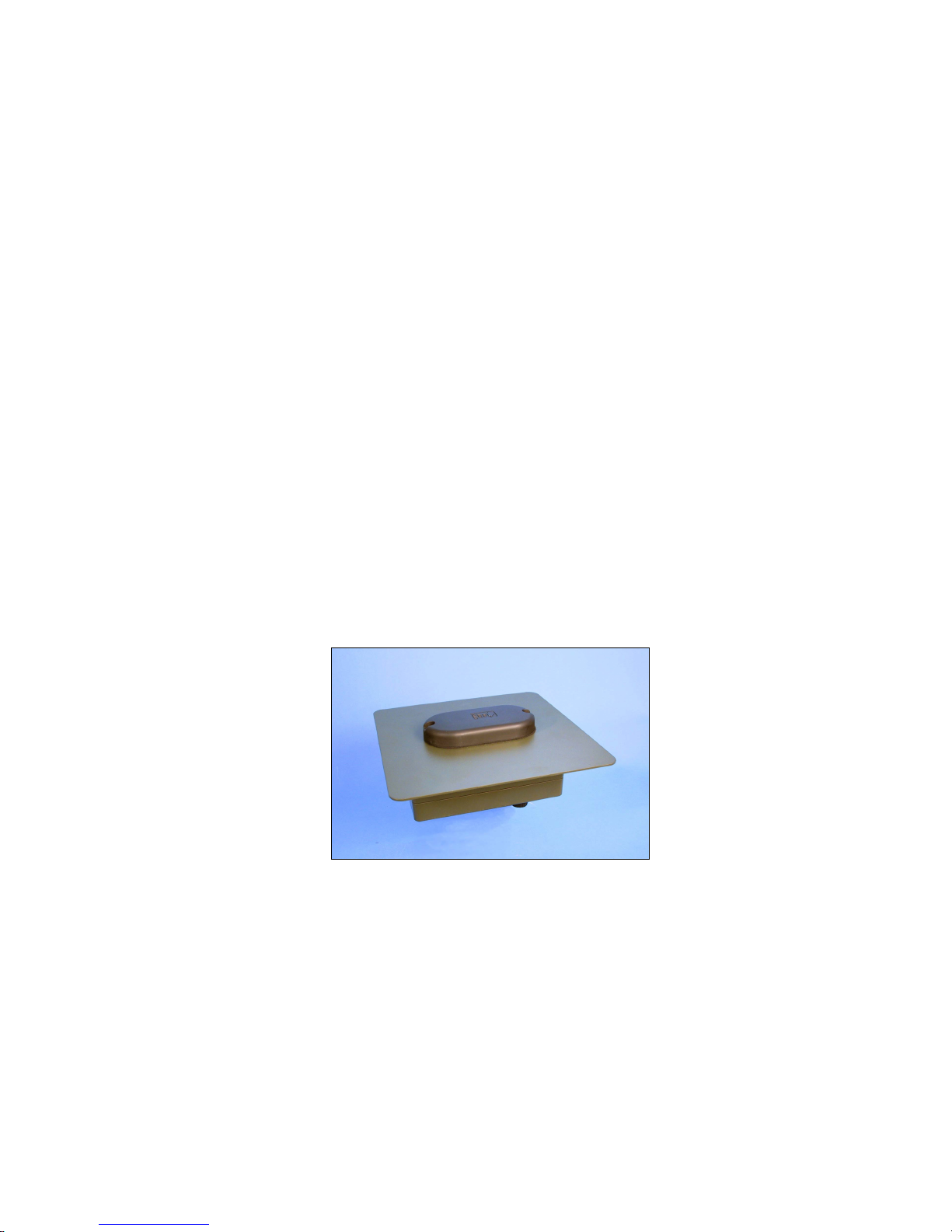
Rain Gauge QMR101M
Figure 11 Rain Gauge QMR101M
Rain Gauge QMR101M is an economical and accurate rain gauge
made of plastic, which is frostproof and highly resistant to UVradiation. QMR101M has a self-emptying tipping spoon of 0.2
millimeters capacity. QMR101M comes with a ready-made cable and
connector.
Ceilometer CT25KAM
Figure 12 Ceilometer CT25KAM

Installation Manual _________________________________________________________________
26 __________________________________________________________________ M210485EN-B
CT25KAM employs pulsed diode laser LIDAR (Light Detection and
Ranging) technology for cloud detection, precipitation, and other
obstructions to vision, and accurate cloud heights and vertical
visibility determination.
The standard measurement range of CT25KAM extends up to 25 000
feet (7.5 km) covering most heights where dense clouds appear. The
instrument is capable of reporting up to three cloud layers
simultaneously. It detects the cloud base reliably in fog, rain, snow,
and haze. If the cloud base is obscured, CT25KAM measures and
reports vertical visibility.
Extensive internal monitoring is supported by a comprehensive set of
user commands that can be given locally or remotely. Internal
monitoring includes a sensor measuring the outgoing laser pulse
energy, circuitry checking the receiver sensitivity, a sensor monitoring
window contamination, and two sensors measuring the tilt angle.
These and other internal measurements are used by the diagnostics
software and the detection algorithm for maximum reliability and ease
of use.
A special additional tilt sensor is provided as standard for
automatically compensating uneven terrain. Installation is made easy
and fast when no exact leveling is required. The cloud coverage
algorithm in the CT25KAM is a further development of the algorithm
specified by FAA. Cloud coverage (amount) is reported in 0 to 8
octas, according to WMO regulations.
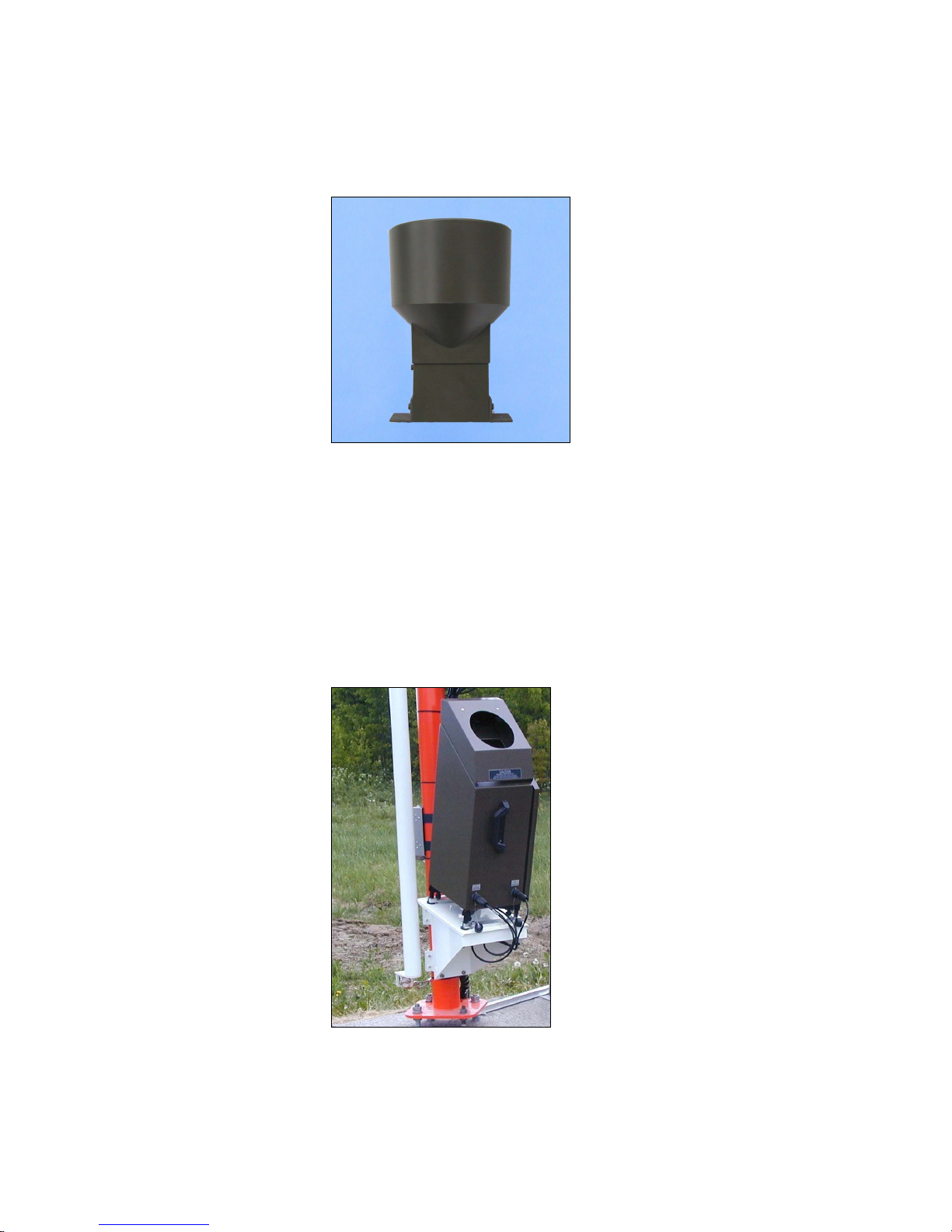
Present Weather Detector PWD11A
Figure 13 Present Weather Detector PWD11A
Present Weather Detector PWD11A is an intelligent multivariable
sensor for automatic weather observing systems. The sensor combines
the functions of a forward scatter visibility meter and a present
Chapter 2 __________________________________________________________ Product Overview
VAISALA _______________________________________________________________________ 27
weather sensor. In addition, PWD11A can measure the intensity and
amount of both liquid and solid precipitation.
The versatility of PWD11A is achieved with a unique operating
principle. PWD11A measures an estimate of the precipitation water
content with a capacitive device and combines this information with
optical scatter and temperature measurements. These three
independent measurements together sufficiently provide data for an
accurate evaluation of the prevailing visibility and weather type.
PWD11A is calibrated with reference to a highly accurate
transmissometer. An extensive self-diagnostic procedure continuously
monitors the sensor status. Dirt and foreign particles on the lens are
detected automatically, minimizing the risk of false high values. A
special calibration kit is provided as an option for conducting field
calibration under practically all weather conditions.
PWD11A is small and lightweight, thus being easy to install on the
sensor cross arm. In addition to the standard sensor operation, the
MAWS software adds extra features such as reporting of coded
weather type identifications as plain text in the output reports.
Lightning Detector SA20M
Figure 14 Lightning Detector SA20M
Lightning Detector SA20M detects the position of lightning activity
and reports lightning and thunderstorm positions with respect to the
location of SA20M. A stand-alone thunderstorm sensor is selfcontained and weather-tight.
The SA20M sensor detects cloud-to-cloud, cloud-to-air and cloud-toground lightning activity to a range of 90 km (50 nmi.). The ability to
detect inter-cloud activity allows SA20M to report lightning during

Installation Manual _________________________________________________________________
28 __________________________________________________________________ M210485EN-B
the building stages of a thunderstorm, before sufficient charge buildup has occurred that would generate a ground strike. Consequently,
SA20M provides early warnings of potentially fatal single-event
ground strikes.
Tiltable Pole Mast
DKP210AV_desert.jpg
Figure 15 Tiltable Pole Mast DKP210AV-T
DKP206AV-T and DKP210AV-T tiltable pole masts can be easily
operated by one person when installing and maintaining the devices
installed on the mast. Also special attention has been paid to easiness
and quickness of the mast installation. The height of DKP206AV-T is
6 m (20 ft) and DKP210AV-T is 10 m (33 ft).
 Loading...