

Page 1

M211972EN-B
User Guide
Vaisala PEROXCAPâ Hydrogen Peroxide,
Humidity and Temperature Probe
HPP272
Page 2

PUBLISHED BY
Vaisala Oyj
Street address: Vanha Nurmijärventie 21, FI-01670 Vantaa, Finland
Mailing address: P.O. Box 26, FI-00421 Helsinki, Finland
Phone: +358 9 8949 1
Visit our Internet pages at www.vaisala.com.
© Vaisala 2017
No part of this manual may be
reproduced, published or publicly
displayed in any form or by any
means, electronic or mechanical
(including photocopying), nor
may its contents be modified,
translated, adapted, sold or
disclosed to a third party without
prior written permission of the
copyright holder. Translated
manuals and translated portions
of multilingual documents are
based on the original English
versions. In ambiguous cases, the
English versions are applicable,
not the translations.
The contents of this manual are
subject to change without prior
notice.
Local rules and regulations may
vary and they shall take
precedence over the information
contained in this manual. Vaisala
makes no representations on this
manual’s compliance with the
local rules and regulations
applicable at any given time, and
hereby disclaims any and all
responsibilities related thereto.
This manual does not create any
legally binding obligations for
Vaisala towards customers or end
users. All legally binding
obligations and agreements are
included exclusively in the
applicable supply contract or the
General Conditions of Sale and
General Conditions of Service of
Vaisala.
This product contains software
developed by Vaisala or third
parties. Use of the software is
governed by license terms and
conditions included in the
applicable supply contract or, in
the absence of separate license
terms and conditions, by the
General License Conditions of
Vaisala Group.
Page 3

Table of Contents
Table of Contents
1. About This Document................................................................................... 5
1.1 Version Information..........................................................................................5
1.2 Related Manuals................................................................................................5
1.3 Documentation Conventions...........................................................................5
1.4 Trademarks........................................................................................................ 6
1.5 Patent Notice.....................................................................................................6
2. Product Overview........................................................................................... 7
2.1 Introduction to HPP272....................................................................................7
2.2 Basic Features and Options.............................................................................8
2.3 Safety..................................................................................................................8
2.4 ESD Protection.................................................................................................. 9
2.5 Measured Parameters.......................................................................................9
2.5.1 Understanding Relative Humidity and Relative Saturation................ 10
2.6 Probe Filter........................................................................................................11
2.7 Chemical Purge.................................................................................................11
2.8 Environmental Compensation for Pressure..................................................12
2.9 Measurement Filtering Factor........................................................................12
2.10 Connectivity to Vaisala Insight Software......................................................12
2.11 Additional Features with Indigo Transmitters..............................................13
3. H2O2 Measurement....................................................................................... 14
3.1 Operating Principle of H2O2 Measurement.................................................. 14
3.2 Typical Applications........................................................................................16
3.3 Condensation Monitoring...............................................................................18
4. Installation.......................................................................................................20
4.1 Wiring...............................................................................................................22
4.2 Power Supply.................................................................................................. 23
4.3 Setting Probe in Analog or Digital Mode.....................................................23
5. Operation......................................................................................................... 25
5.1 Probe Start-Up................................................................................................25
5.2 Behavior at Exposure to H2O2.......................................................................25
5.3 H2O2 Concentration Reading When Not Exposed to H2O2.......................25
5.4 Modbus............................................................................................................ 26
5.5 Operation in Analog Mode............................................................................26
5.5.1 Analog Output Overrange Behavior.....................................................26
5.5.2 Triggering Purge in Analog Mode......................................................... 27
6. Vaisala Insight Software............................................................................ 28
6.1 Connecting to Insight Software....................................................................28
1
Page 4

HPP272 User Guide M211972EN-B
7. Using Probe with Indigo Transmitters................................................. 29
7.1 Indigo Overview............................................................................................. 29
7.1.1 Wireless Configuration Interface Overview.........................................30
7.2 Attaching Probes.............................................................................................31
7.3 Connecting to Wireless Configuration Interface........................................ 32
7.4 Logging in to Wireless Configuration Interface..........................................33
8. Maintenance....................................................................................................34
8.1 Cleaning the Probe.........................................................................................34
8.1.1 Chemical Tolerance................................................................................. 34
8.2 Calibration and Adjustment.......................................................................... 35
9. Troubleshooting............................................................................................ 36
9.1 Problems and Their Possible Solutions........................................................36
9.2 Analog Output Error State............................................................................40
10. Technical Data................................................................................................. 41
10.1 Dimensions...................................................................................................... 43
10.2 Accessories.....................................................................................................44
Appendix A:
Modbus Reference........................................................................45
A.1 Default Communication Settings................................................................. 45
A.2 Function Codes...............................................................................................45
A.3 Data Encoding................................................................................................45
A.3.1 32-Bit Floating Point or Integer Format...............................................45
A.3.2 16-Bit Integer Format............................................................................. 46
A.4 Modbus Registers...........................................................................................46
A.4.1 Measurement Data Registers.................................................................47
A.4.2 Configuration Registers......................................................................... 48
A.4.3 Status Registers...................................................................................... 54
A.4.4 Device Identification Objects.................................................................56
A.4.5 Test Value Registers................................................................................ 57
A.5 Modbus Communication Examples..............................................................58
Warranty........................................................................................................................ 61
Technical Support...................................................................................................... 61
Recycling....................................................................................................................... 61
2
Page 5

List of Figures
Figure 1 HPP272 Probe Parts...........................................................................................7
Figure 2 Eect of H2O and H2O2 on relative saturation (RS) and
relative humidity (RH).....................................................................................10
Figure 3 Operating principle of PEROXCAP measurement................................... 15
Figure 4 Example behavior of H2O2 concentration, relative
saturation (RS), and relative humidity (RH) in a
vaporized H2O2 bio-decontamination cycle (non-
condensing conditions)...................................................................................17
Figure 5 Example: RS behavior in dierent temperatures when
H2O2 concentration (500 ppm) and H2O concentration
(8850 ppm) are constant............................................................................... 18
Figure 6 Decontaminated space with dierent temperatures and
RS levels (H2O2 and H2O concentration evenly distributed)................19
Figure 7 Probe M12/5 Pins..............................................................................................22
Figure 8 Wiring Example for Connecting HPP272 to a PLC in
Analog Mode..................................................................................................... 23
Figure 9 Pins on the M12 male connector.................................................................. 24
Figure 10 Connecting Probe to Insight.........................................................................28
Figure 11 Attaching Probes to Indigo............................................................................31
Figure 12 Enabling and Accessing Indigo's Wireless Configuration
Interface..............................................................................................................32
Figure 13 Indigo Login View............................................................................................33
Figure 14 HPP272 Dimensions........................................................................................ 43
List of Figures
3
Page 6

HPP272 User Guide M211972EN-B
List of Tables
Table 1 Document Versions..............................................................................................5
Table 2 Related Manuals....................................................................................................5
Table 3 Applicable Patents or Applications.................................................................6
Table 4 Available Parameters...........................................................................................9
Table 5 Measurement Performance..............................................................................41
Table 6 Inputs and Outputs............................................................................................42
Table 7 Mechanical Specifications............................................................................... 43
Table 8 Operating Environment....................................................................................43
Table 9 Spare Parts and Accessories.......................................................................... 44
Table 10 Default Modbus Serial Communication Settings...................................... 45
Table 11 Modbus Function Codes.................................................................................. 45
Table 12 16-bit Signed Integer Format Details........................................................... 46
Table 13 Modbus Measurement Data Registers (Read-Only).................................47
Table 14 Modbus Configuration Data Registers (Writable)....................................49
Table 15 Modbus Status Registers (Read-Only)........................................................ 54
Table 16 Error Codes in Register 0201
Table 17 Error Codes in Register 0203
Table 18 Device Identification Objects......................................................................... 56
Table 19 Test Value Registers...........................................................................................57
(32-bit)..................................................... 55
hex
(32-bit).................................................... 56
hex
4
Page 7

Chapter 1 – About This Document
1. About This Document
1.1 Version Information
This document provides instructions for installing, using, and maintaining Vaisala PEROXCAPâ
Hydrogen Peroxide, Humidity and Temperature Probe HPP272.
Table 1 Document Versions
Document
Code
M211972EN-B December 2017 This document. Added description and Modbus registers for
M211972EN-A September 2017 First version.
Date Description
pressure compensation, removed restriction not to perform a
purge during H2O2 exposure, clarified operating system
requirements for Vaisala Insight software, clarified Indigo
200 transmitter compatibility with HPP272.
1.2 Related Manuals
Table 2 Related Manuals
Document Code Name
M211887EN Hydrogen Peroxide, Humidity and Temperature Probe HPP270 Series Quick
M211877EN Indigo 201 Analog Output Transmitter User Guide
Guide
1.3 Documentation Conventions
WARNING!
follow instructions carefully at this point, there is a risk of injury or even death.
Warning alerts you to a serious hazard. If you do not read and
CAUTION!
follow instructions carefully at this point, the product could be damaged or
important data could be lost.
Caution warns you of a potential hazard. If you do not read and
5
Page 8

HPP272 User Guide M211972EN-B
Note highlights important information on using the product.
Tip gives information for using the product more eciently.
Lists tools needed to perform the task.
Indicates that you need to take some notes during the task.
1.4 Trademarks
Vaisalaâ, HUMICAPâ, and PEROXCAPâ are registered trademarks of Vaisala Oyj.
Indigo™ is a trademark of Vaisala Oyj.
All other product or company names that may be mentioned in this publication are trade
names, trademarks, or registered trademarks of their respective owners.
1.5
Patent Notice
This product is protected by the following patents and patent applications and their
corresponding national rights:
Table 3 Applicable Patents or Applications
Issuing Oce Publication Number
European Patent Oce EP 3004868
State Intellectual Property Oce of the P.R.C. CN 105229463A
United States Patent and Trademark Oce US 20160084811
6
Page 9

21 543
6
Chapter 2 – Product Overview
2. Product Overview
2.1 Introduction to HPP272
Vaisala PEROXCAPâ Hydrogen Peroxide, Humidity and Temperature Probe HPP270 series is
designed for demanding hydrogen peroxide bio-decontamination processes. The probes are
suitable for a variety of applications such as isolator, material transfer hatch, and room biodecontamination.
Hydrogen Peroxide, Humidity and Temperature Probe HPP272 provides measurement for
vaporized H2O2 concentration, relative saturation, relative humidity, and temperature.
The H2O2 measurement is based on comparing the readings of two composite humidity
sensors to determine the vapor concentration of H2O2. The probes are easy to install with a
plug-in/plug-out M12/5 connection. The digital and analog output options include an RS-485
interface for Modbus communication and two current output channels.
The probe is not intended for safety level measurement.
The probe is not intended to be used in vacuum applications.
CAUTION!
always be powered on. When powered on, the PEROXCAP sensor is heated,
which permits using the probe in condensing H2O2 conditions, maintains
measurement performance, and lengthens the probe's lifetime. When the probe
is powered o, exposure to H2O2 condensation can break the PEROXCAP sensor
within a day, and the sensor will not recover.
When there is H2O2 in the probe's environment, the probe must
Figure 1 HPP272 Probe Parts
1 Yellow transport cap. Remove this cap
before using the probe.
2 Filter covering the sensor. The filter is
an essential part of the measurement
technology: do not remove the filter.
Filters are available as spare parts.
3 PEROXCAP sensor under the filter.
4 H2O2 and humidity probe.
5 Temperature probe.
6 5-pin M12 connector.
7
Page 10

HPP272 User Guide M211972EN-B
More Information
‣
Dimensions (page 43)
‣
Operating Principle of H2O2 Measurement (page 14)
‣
Installation (page 20)
‣
Wiring (page 22)
2.2 Basic Features and Options
• Vaisala PEROXCAPâ H2O2 measurement technology with excellent long-term stability.
• Vaporized H2O2 measurement range 0 ... 2000 ppm.
• Relative saturation (RS) measurement range 0 ... 100 %RS.
• Relative humidity (RH) measurement range 0 … 100 %RH.
• Temperature (T) measurement range +5 ... +70 °C.
• Robust design allowing the probe to be installed directly in the process environment.
When powered on, the probe withstands H2O2 and H2O condensation. The probe also
withstands nitrogen gas.
• Protective
• Sensor heating to avoid condensation on the sensors.
• Chemical purge for optimized performance and lifetime.
• Pressure compensation for H2O2 concentration (ppm), H2O concentration (ppm), and
relative saturation (%RS) measurement.
• Digital output: RS-485 interface for Modbus communication.
• Analog output: 2 x 4 ... 20 mA (default).
• Easy plug-in, plug-out.
• Can be used as a stand-alone probe or with Vaisala Indigo 200 series transmitters.
• Can be connected to Vaisala Insight software for
temporary online monitoring.
filter over the sensors designed to withstand high air flow rates and turbulence.
configuration, diagnostics, and
More Information
‣
Technical Data (page 41)
2.3
Safety
WARNING!
to minimize shock hazard.
WARNING!
has not been exposed to dangerous contamination, and is safe to handle
without special precautions.
8
Ground the product and verify installation grounding periodically
When returning a product for calibration or repair, make sure it
Page 11

Chapter 2 – Product Overview
CAUTION!
Do not attempt to open the probe body. There are no user
serviceable parts inside the probe body.
2.4 ESD Protection
Electrostatic Discharge (ESD) can cause immediate or latent damage to electronic circuits.
Vaisala products are adequately protected against ESD for their intended use. However, it is
possible to damage the product by delivering an electrostatic discharge when touching,
removing or inserting any objects inside the equipment housing.
Avoid touching component contacts or connectors when working with the device.
2.5 Measured Parameters
Table 4 Available Parameters
Parameter Unit
Vaporized hydrogen peroxide concentration by
volume
Relative saturation (RS) (H2O + H2O2) %RS
Relative humidity (RH) (H2O) %RH
Temperature °C
Absolute hydrogen peroxide
Absolute humidity (H2O)
Water concentration by volume ppm
Water vapor pressure hPa
Water vapor saturation pressure hPa
ppm
mg/m
g/m
3
3
The probe provides both digital and analog outputs.
• In digital output mode, the probe outputs all the measurement parameters.
• In analog output mode, the probe outputs the readings of two measurement parameters
(one parameter in each analog output channel). These measurement parameters are
chosen at the time of ordering the probe, and you can change them using Insight
software and via Modbus. The probe is also compatible with Vaisala Indigo transmitters,
which provide the option of three analog output channels.
9
Page 12
%RH%RS
00
100100
H2O
H2O
2
%RS %RH
0 0
100
100
H2O
1 2
HPP272 User Guide M211972EN-B
More Information
‣
Understanding Relative Humidity and Relative Saturation (page 10)
‣
Measurement Data Registers (page 47)
‣
Configuration Registers (page 48)
‣
Connectivity to Vaisala Insight Software (page 12)
‣
Setting Probe in Analog or Digital Mode (page 23)
2.5.1 Understanding Relative Humidity and Relative Saturation
Water and hydrogen peroxide have a very similar molecular structure, and they both aect the
humidity of the air in which they are present. HPP272 measurement makes a
between the humidity caused by both H2O2 vapor and water vapor, and the humidity caused
only by water vapor:
• Relative saturation is a parameter that indicates the humidity of the air caused by both
H2O2 vapor and water vapor. When relative saturation reaches 100 %RS, the vapor
mixture starts to condense.
• Relative humidity is a parameter that indicates the humidity of the air caused only by
water vapor.
dierence
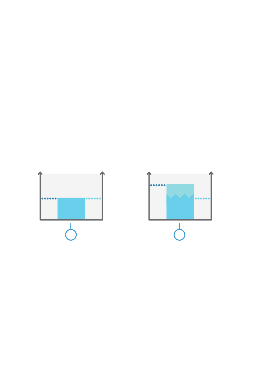
Figure 2 Eect of H2O and H2O2 on relative saturation (RS) and relative humidity (RH)
Space without H2O2 vapor. When H2O2 vapor is not present, relative saturation equals
1
relative humidity.
2 Same space with H2O2 vapor introduced. Relative saturation is higher than relative
humidity.
During H2O2 bio-decontamination processes, it is often important to monitor the possibility of
condensation. For this purpose, it is not enough to know the level of relative humidity (RH),
because RH only indicates the humidity caused by water vapor. The possibility of
condensation is
aected by the combined humidity of H2O2 vapor and water vapor, which is
why you need to monitor relative saturation (RS).
10
Page 13

Chapter 2 – Product Overview
2.6 Probe Filter
The white filter on the probe covers the PEROXCAP sensor. The filter is made of porous PTFE
that allows ambient air to reach the PEROXCAP sensor while protecting the sensor in strong or
turbulent air flow.
CAUTION!
broken, dirty, or removed altogether, measurement does not work as intended.
• Do not touch the
use clean gloves (rubber, cotton or similar material).
• Keep the
• Do not touch any parts under the filter. Touching parts under the filter may
damage the sensors.
More Information
‣
Problems and Their Possible Solutions (page 36)
2.7
Chemical Purge
Chemical purge is a 4-minute process where the sensors are heated to remove possible
contamination. The purge is essential for the long-term performance and accuracy of the
probe in demanding H2O2 environments. During the purge, only temperature measurement is
available.
The purge is automatically performed:
• At probe start-up.
• At intervals (default 24 hours,
software, Modbus, or Indigo 200 transmitters). Purge is postponed by 30 minutes if H2O
is present or RH is not steady.
Purge is recommended at least every 24 hours of powered-on time, even if the probe has not
been continuously exposed to H2O2.
Optional: if needed, you can also trigger a purge manually with Modbus (in digital mode) or
pin #5 on the M12 connector (in analog mode).
The filter is an essential part of the measurement. If the filter is
filter with bare hands. If you need to touch the filter, always
filter free of any grease or oil.
configurable between 1 hour ... 1 week using Vaisala Insight
2
More Information
‣
Triggering Purge in Analog Mode (page 27)
‣
Operation in Analog Mode (page 26)
11
Page 14

HPP272 User Guide M211972EN-B
2.8 Environmental Compensation for Pressure
When necessary, you can apply pressure compensation to improve the measurement accuracy
of the probe (probe software v.1.1.0 and later). The probe does not have on-board pressure
measurement, but a pressure reading from an external source can be used as a setpoint value
for compensation.
You can configure the pressure compensation parameters using Vaisala Insight software,
Modbus configuration registers, or an Indigo 200 transmitter.
By default, the pressure compensation is turned o. When the compensation is o, the probe
uses the default compensation value (1013.25 hPa).
Pressure compensation
• H2O2 concentration (ppm)
• H2O concentration (ppm)
• Relative saturation (%RS)
More Information
‣
Vaisala Insight Software (page 28)
‣
Configuration Registers (page 48)
2.9
Measurement Filtering Factor
You can set a filtering factor that aects the speed at which the latest H2O2 and RS
measurements are integrated into the output of the probe. This allows averaging the output if
the measuring environment produces occasional exceptionally high or low readings.
filtering factor can be set either with Modbus configuration register 0308
The
Insight software, or an Indigo 200 transmitter.
By default, the
directly in the output, without any filtering. To apply filtering, enter a lower filtering factor to
include previous measurements in the calculation of measurement output. For example,
changing the
measurement (90%) and the previous measurement output (10%).
filtering factor to 0.9 results in an output that is a combination of the latest
aects the following parameters:
, Vaisala
hex
filtering factor is set to 1.0, which means the latest measurement is shown
More Information
‣
Configuration Registers (page 48)
2.10
Connectivity to Vaisala Insight Software
The probe can be connected to Vaisala Insight software using a Vaisala USB cable (no.
242659). With the Insight software, you can:
• See device information and status.
12
Page 15

Chapter 2 – Product Overview
• See real-time measurement.
• Configure serial communication settings, purge settings, filtering factor, and analog
output parameters and scaling.
More Information
‣
Connecting to Insight Software (page 28)
2.11 Additional Features with Indigo Transmitters
The probes are compatible with Vaisala Indigo 200 transmitters starting from Indigo
transmitter serial number N4650357 (Indigo 200 transmitter software version 1.3.2 or higher).
Connecting the probe to an Indigo transmitter provides a range of additional options for
outputs, measurement viewing, status monitoring, and
Examples of additional features available with Indigo transmitters include:
• 3.5” TFT LCD color display or non-display model with LED indicator
• Digital output or 3 analog outputs (depending on the transmitter model)
• 2 configurable relays
• Wireless browser-based configuration interface for mobile devices and computers (IEEE
802.11 b/g/n WLAN)
The selection of available additional features (for example, output and connectivity options)
varies depending on the Indigo transmitter model. For more information on Indigo
transmitters, see www.vaisala.com/indigo.
More Information
‣
Indigo Overview (page 29)
configuration interface access.
13
Page 16

HPP272 User Guide M211972EN-B
3. H2O2 Measurement
3.1 Operating Principle of H2O2 Measurement
CAUTION!
always be powered on. When powered on, the PEROXCAP sensor is heated,
which permits using the probe in condensing H2O2 conditions, maintains
measurement performance, and lengthens the probe's lifetime. When the probe
is powered o, exposure to H2O2 condensation can break the PEROXCAP sensor
within a day, and the sensor will not recover.
PEROXCAPâ sensor technology works using measurements from two Vaisala HUMICAPâ
sensors. HUMICAP sensors guarantee quality and reliability, with their reputation for
repeatability, accuracy, excellent long-term stability, and negligible hysteresis – even in the
most demanding high-concentration H2O2 applications in atmospheric pressure.
HUMICAP sensor is a
polymer film is deposited between two electrodes. The film absorbs or releases vapor
according to humidity changes in the environment. As the humidity changes, the dielectric
properties of the polymer
instrument’s electronics measure the capacitance of the sensor and convert it into a humidity
reading.
PEROXCAP measurement uses two composite HUMICAP sensors, one with a catalytic layer
and one without. The catalytic layer catalyzes H2O2 from the vapor mixture. Therefore, the
HUMICAP sensor with this layer only senses water vapor, providing a measurement of partial
water pressure, i.e. relative humidity (RH). The sensor without the catalytic layer senses both
hydrogen peroxide vapor and water vapor in the air mixture. The
readings from these two sensors indicates the vapor concentration of H2O2.
When there is H2O2 in the probe's environment, the probe must
thin-film polymer sensor consisting of a substrate on which a thin
film change, and so does the capacitance of the sensor. The
dierence between the
14
Page 17

H20
2
H20
2H20
0
2
2H20
2
H20
2
1
3
2
3
A B
Chapter 3 – H2O2 Measurement
Figure 3 Operating principle of PEROXCAP measurement
HUMICAP sensor with a catalytic layer (under the probe filter). This sensor only senses
A
water vapor.
B HUMICAP sensor without a catalytic layer (under the probe filter). This sensor senses the
air mixture with both hydrogen peroxide vapor and water vapor.
1 Catalytic layer over the thin film polymer. This layer catalyzes hydrogen peroxide into
water and oxygen and prevents it from entering the sensing polymer.
2 Thin film polymer between two electrodes.
3 Alumina substrate.
In addition to measuring vaporized H2O2 concentration, HPP272 provides measurement for
relative saturation, relative humidity, and temperature. Relative humidity (RH) is a parameter
that indicates the humidity value derived from water vapor only, whereas relative saturation
(RS) indicates the humidity percentage derived from water vapor and H2O2 vapor together.
When relative saturation reaches 100 %RS, the vapor mixture starts to condense.
15
Page 18

HPP272 User Guide M211972EN-B
3.2 Typical Applications
The probe is not intended for safety level measurement.
The probe is not intended to be used in vacuum applications.
Vaporized hydrogen peroxide is used for bio-decontamination in several applications from
healthcare and pharmaceutics to food and beverage industry. Vaporized hydrogen peroxide is
an easy-to-use and eective bio-decontaminating agent that destroys the full spectrum of
biological contaminants including micro-organisms such as bacterial spores, mycobacteria,
and non-enveloped, non-lipid viruses. Bio-decontamination with vaporized hydrogen peroxide
is a low-temperature, environmentally friendly process that leaves no real residues, only water
vapor and oxygen. One of the
validated.
Common vaporized H2O2 bio-decontamination applications include isolators, transfer hatches,
closed Restricted Access Barrier Systems, and room bio-decontamination (for example, in
hospital environments, cleanrooms, decontamination tents, aircrafts, ships, and shipping
containers).
The bio-decontamination process typically has the following phases:
1. Optional dehumidification, where relative humidity is decreased to a desired level, for
example, by warming the space.
2. Conditioning, where vaporized H2O2 mixture is introduced into the space to be biodecontaminated.
3. Decontamination, where H2O2 concentration is maintained at a desired level for a certain
time.
4. Aeration, where H2O2 is removed from the bio-decontaminated space.
benefits also is that the bio-decontamination process can be
16
Page 19

100%
0%
More
Less
Cycle Phase
Aeration
Decontamination
Conditioning
Dehumidification
CONDENSATION POINT
RELATIVE
SATURATION (RS)
RELATIVE HUMIDITY (RH)
VAPORIZED HYDROGEN
PEROXIDE CONCENTRATION
Humidity
H2O
2
Concentration
Chapter 3 – H2O2 Measurement
Figure 4 Example behavior of H2O2 concentration, relative saturation (RS), and relative humidity
(RH) in a vaporized H2O2 bio-decontamination cycle (non-condensing conditions)
In the non-condensing bio-decontamination cycle example shown in Figure 4 (page 17):
• In the dehumidification phase, RH (and RS) decreases.
• When the conditioning phase starts, H2O2 concentration rises rapidly. There is also a rapid
increase in RS, which indicates the humidity caused by both H2O2 vapor and water vapor.
Because the generated H2O2 vapor is typically mixed with water vapor, RH also starts to
rise.
• In the decontamination phase, H2O2 concentration is steady. However, RS level rises slowly
close to 100 %RS, i.e. condensation point, due to rising RH level.
• In the aeration phase, H2O2 concentration, RS, and RH all decrease. When H2O
2
concentration is zero, RS equals RH.
The way your bio-decontamination process is designed
measure in dierent phases.
Depending on your bio-decontamination process, you may also want to either create or avoid
condensation during the conditioning and decontamination phases. In these phases, the air in
the bio-decontaminated space always contains both water and H2O2 vapor, which both
the possibility of condensation. To monitor and control whether and when condensation
forms, it is useful to know the combined humidity level of water vapor and H2O2 vapor: relative
aects which parameters you want to
saturation (RS). When relative saturation reaches 100 %RS, the vapor mixture starts to
condense.
aect
17
Page 20

Temperature
Relative saturation
21 21.5 22 22.5
100
95
85
90
H2O2 = 500 ppm
H2O = 8850 ppm
HPP272 User Guide M211972EN-B
For condensation monitoring, choosing the right measurement location is very important. If
the bio-decontaminated space has surfaces with a lower temperature than where RS is
measured, condensation may start to form on those surfaces even before RS reaches 100 %RS
in the exact measurement location. To monitor the possibility of condensation, consider
installing the probe close to a surface where you suspect condensation may form.
More Information
‣
Understanding Relative Humidity and Relative Saturation (page 10)
‣
Installation (page 20)
3.3 Condensation Monitoring
H2O+H2O2 vapor mixture starts to condense when relative saturation (RS) reaches 100 %RS.
RS level is strongly aected by temperature: decreasing the temperature increases RS. If there
are temperature
that space even if the H2O+H2O2 vapor is evenly distributed.
dierences in the bio-decontaminated space, RS varies in dierent parts of
Figure 5 Example: RS behavior in dierent temperatures when H2O2 concentration (500 ppm) and
H2O concentration (8850 ppm) are constant
For condensation monitoring, this means that even if you measure < 100 %RS in one point, RS
may be 100 %RS in another, cooler point. The following
can vary in a decontaminated space according to temperature dierences.
18
figure shows an example of how RS
Page 21

3
1
2
T= 21.5 ˚C
RS= 94.5 %RS
T= 22 ˚C
RS= 89.5 %RS
T= 21 ˚C
RS= 100 %RS
Chapter 3 – H2O2 Measurement
Figure 6 Decontaminated space with dierent temperatures and RS levels (H2O2 and H2O
concentration evenly distributed)
1 Center of the decontaminated space. The center is warmer than the wall and the window,
and the RS level is lower.
2 Wall of the decontaminated space. Because the wall is 0.5 °C cooler than the center of the
space, RS level is higher than in the center.
3 Window of the decontaminated space. The window is 1 °C cooler than the center of the
space, and RS = 100 %RS. Condensation starts to form on the window surface.
Condensation forms typically on surfaces, and first on surfaces that are cooler than the
surrounding air, such as:
To monitor the possibility of condensation by measuring RS, it is recommended to measure as
close as possible to places where condensation might occur.
• Walls
• Windows
• Supplies that have just been brought in the decontaminated space
19
Page 22

HPP272 User Guide M211972EN-B
4. Installation
Accurate RH and RS measurement requires both humidity and temperature data from the
same environment. Install the H2O2 and humidity probe and the temperature probe in the
same measurement environment and temperature, approximately 6 ... 10 cm apart from each
other. Do not install the temperature probe directly above the H2O2 and humidity probe, as
moderate heat rising up from the H2O2 and humidity probe body may aect the ambient
temperature around the temperature probe.
When you choose the installation location for the probe, consider the following:
• Choose a location that represents the environment and process you want to measure.
Some factors may make a location unrepresentative of the process:
• Heat sources
• Materials that absorb H2O2, such as several plastics, rubbers and sealing materials
• Limited air
• The probes withstand bio-decontamination process conditions. For signal cables, you
must verify their suitability in the installation environment.
• The probes withstand high air flow rates.
• For condensation monitoring with relative saturation, consider installing the probe close
to a surface where condensation may form (typically, on cooler surfaces in the biodecontaminated space).
• The probe is intended for use in atmospheric pressure. Do not install the probe in a
vacuum.
When there is H2O2 in the probe's environment, the probe must always be powered on. When
powered on, the PEROXCAP sensor is heated, which permits using the probe in condensing
H2O2 conditions, maintains measurement performance, and lengthens the probe's lifetime.
flow
20
CAUTION!
broken, dirty, or removed altogether, measurement does not work as intended.
• Do not touch the
use clean gloves (rubber, cotton or similar material).
• Keep the
• Do not touch any parts under the filter. Touching parts under the filter may
damage the sensors.
The filter is an essential part of the measurement. If the filter is
filter with bare hands. If you need to touch the filter, always
filter free of any grease or oil.
Page 23

6 ... 10 cm
≤ 6 mm
Ø 40 mm
Ø 8 mm
1
2
4 cm
(recommended)
6 ... 10 cm
Chapter 4 – Installation
Example: Installation Through a Wall
A through-wall installation is
recommended especially in very harsh
processes.
Seal the lead-throughs on the metal body
of the probes.
The figure shows an example installation
using Vaisala spare part glands
(HPP272MOUNTINGSET1).
1 Nut for tightening the probe in place
2 Nut for mounting the gland
Example: Installation Entirely in Process Environment
Mount the H2O2 and humidity probe from
the probe body.
Mount the temperature probe from the
metal body. Note that the temperature
sensor is at the tip of the temperature
probe.
Let the signal cable hang loosely so that it
makes a bend. This prevents condensing
water from running to the probe along the
cable. Do not hang the probe by the signal
cable.
Make sure the signal cable you
use is suitable for your biodecontamination process.
21
Page 24

1
5
3
4
2
HPP272 User Guide M211972EN-B
4.1 Wiring
Figure 7 Probe M12/5 Pins
Pin # Function Notes Wire
1 Power supply With digital output: 15 ... 30 VDC
With analog output: 15 ... 25 VDC
When using analog outputs, it is recommended to
use a low supply voltage to minimize self-heating
and maximize measurement performance.
2 RS-485- or analog
output 2
3 Power and signal GND Blue
4 RS-485+ or analog
output 1
5 Output control and purge
trigger in analog mode
1) Wire colors apply to the following cables: 223263SP, 26719SP, 26720SP, 216546SP,
244669SP
2) The ordered parameters and scaling are shown in the calibration certificate delivered with
the probe.
Current output: 4 … 20 mA (default).
Current output: 4…20 mA (default)
Floating = RS-485
Grounded = Analog outputs
If you want to be able to trigger a purge manually in
the analog mode, do not connect pin #5
permanently to ground, but instead, use a relay or
similar to control the pin.
2)
2)
Color
1)
Brown
White
Black
Grey
22
Page 25

PLC
DC power
supply
IN+ Current input
IN-
IN+ Current input
IN-
Relay/switch
control
+
-
Pin #1
(Power supply)
Pin #2
(Analog output 2)
Pin #3
(Power and signal
GND)
Pin #4
(Analog output 1 )
Pin #5
(Output control
and purge trigger
in analog mode)
HPP270 series
probe
Figure 8 Wiring Example for Connecting HPP272 to a PLC in Analog Mode
More Information
‣
Accessories (page 44)
‣
Triggering Purge in Analog Mode (page 27)
4.2
Power Supply
Chapter 4 – Installation
Operating voltage range of the probe:
Maximum current consumption at 25 °C:
4.3
The probe has two output modes: digital mode (RS-485 using Modbus) and analog mode
(current output).
Both the digital output and analog output use the same pins in the M12 male connector (pins
#2 and #4), but only one of the output modes can be active at the same time. You select which
output mode is active with the output control pin #5.
• With digital output: 15 ... 30 VDC
• With analog output: 15 ... 25 VDC
• With digital output: 15 mA
• With analog output: 50 mA
• During purge: 200 mA
Setting Probe in Analog or Digital Mode
23
Page 26

1
5
3
4
2
HPP272 User Guide M211972EN-B
Figure 9 Pins on the M12 male connector
1. If the probe is powered on, power o the probe.
2. Select the output mode with pin #5:
a. To set the probe in analog mode, connect pin #5 to ground.
b. To set the probe in digital mode, leave pin #5
3. Power on the probe. The probe checks the state of pin #5 (grounded or floating) and goes
in the selected output mode.
floating.
24
Page 27

Chapter 5 – Operation
5. Operation
5.1 Probe Start-Up
When powered on, the probe starts up within 2 seconds and the digital/analog outputs are
activated. The probe performs a start-up purge, which takes approximately 4 minutes. During
the purge, hydrogen peroxide, relative humidity, and relative saturation measurements are not
available. If the probe is in analog mode, analog outputs are in the error state (default: 3.6 mA)
during the purge.
Measurements from the outputs (digital and analog) will reach
minute warm-up period. For this reason, you should design your system so that it does not rely
on measurements from the probe during this time.
More Information
‣
Behavior at Exposure to H2O2 (page 25)
5.2
Behavior at Exposure to H2O
specified accuracy after a 8½-
2
CAUTION!
always be powered on. When powered on, the PEROXCAP sensor is heated,
which permits using the probe in condensing H2O2 conditions, maintains
measurement performance, and lengthens the probe's lifetime. When the probe
is powered o, exposure to H2O2 condensation can break the PEROXCAP sensor
within a day, and the sensor will not recover.
When the bio-decontamination process starts and the probe is exposed to H2O2, the probe's
H2O2 concentration reading changes to > 0 ppm after approximately 20 ... 30 seconds. This
time is included in the response time of the probe.
5.3
H2O2 Concentration Reading When Not
Exposed to H2O
The PEROXCAP sensor consists of two humidity sensors that have a minor dierence in
behavior when the humidity level changes. Because of this
reading may vary slightly (typically 0 … 3 ppm) when the probe is not exposed to H2O2. This
variation is normal and does not require any actions. If needed, you can hide the variation by
setting a low clipping limit with the Vaisala Insight software, Modbus
030C
, or an Indigo 200 transmitter. For example, if you set the low clipping limit to 3 ppm,
hex
any reading < 3 ppm is clipped to show 0 ppm.
When there is H2O2 in the probe's environment, the probe must
2
dierence, the H2O2 concentration
configuration register
25
Page 28

HPP272 User Guide M211972EN-B
More Information
‣
Vaisala Insight Software (page 28)
‣
Configuration Registers (page 48)
5.4 Modbus
The probe can be accessed using the Modbus serial communication protocol. The supported
Modbus variant is Modbus RTU (Serial Modbus) over RS-485 interface.
More Information
‣
Modbus Reference (page 45)
‣
Setting Probe in Analog or Digital Mode (page 23)
5.5
Operation in Analog Mode
In analog output mode, the probe outputs the readings of two measurement parameters (one
parameter in each analog output channel). These measurement parameters are chosen at the
time of ordering the probe, and you can change them using Insight software and via Modbus.
You can check the chosen parameters in the calibration
The default output range for both channels is 4 ... 20 mA.
When using analog outputs, it is recommended to use a low supply voltage to minimize selfheating and maximize measurement performance. The operating voltage range with analog
output is 15 ... 25 V.
When the probe performs the chemical purge, the analog outputs have a defined behavior:
• During start-up purge, analog output is in the error state (default: 3.6 mA).
• During interval purge and manually triggered purge, output is frozen to show the last
measured value before the purge began.
certificate delivered with the probe.
More Information
‣
Setting Probe in Analog or Digital Mode (page 23)
‣
Analog Output Error State (page 40)
‣
Configuration Registers (page 48)
‣
Chemical Purge (page 11)
5.5.1 Analog Output Overrange Behavior
If the values measured by the probe are outside the scaled analog output range, the analog
output goes in the error state. The default error state is 3.6 mA.
26
Page 29

Chapter 5 – Operation
More Information
‣
Analog Output Error State (page 40)
5.5.2 Triggering Purge in Analog Mode
In the analog mode, pin #5 in the probe's M12 male connector is connected to ground.
Additionally, pin #5 is used to trigger a purge in analog mode. To be able to trigger a purge, do
not connect pin #5 to ground permanently, but instead, use a relay or similar to control the pin.
For a wiring example, see Figure 8 (page 23).
1. To trigger the purge, disconnect pin #5 from ground for a minimum of 50 ms, and then
reconnect the pin to ground.
Do not leave pin #5 floating for a long time. If the probe is reset while pin #5
is floating, the probe will go into digital mode instead of analog mode.
The probe starts performing the purge. The duration of the purge is approximately 4 minutes.
During the purge, hydrogen peroxide, relative saturation, and relative humidity measurements
are not available.
27
Page 30

HPP272 User Guide M211972EN-B
6. Vaisala Insight Software
Vaisala Insight software is a configuration software for Indigo-compatible probes. The
supported operating systems are Windows 7 (64-bit), Windows 8.1 (64-bit), and Windows 10
(64-bit).
With the Insight software, you can:
• See device information and status.
• See real-time measurement.
Configure serial communication settings, purge settings, filtering factor, and analog
•
output parameters and scaling.
• Calibrate and adjust the device.
Download Vaisala Insight software at www.vaisala.com/insight.
The probe can be connected to Vaisala Insight software using a Vaisala USB cable (no.
242659).
6.1
Connecting to Insight Software
• Computer with Insight software installed
• USB connection cable (no. 242659)
Figure 10 Connecting Probe to Insight
1. Open the Vaisala Insight software.
2. Connect the USB cable to a free USB port on the PC.
3. Connect the probe to the USB cable.
4. Wait for the Insight software to recognize and identify the probe.
28
Page 31

1
5
4
2
3
Chapter 7 – Using Probe with Indigo Transmitters
7. Using Probe with Indigo Transmitters
7.1 Indigo Overview
1 3.5” TFT LCD color display: non-display option with LED available for certain models.
2 Cable locking wheel: insert cable, hold in place, and turn the wheel counterclockwise.
3 Wireless configuration interface (WLAN) activation button.
4 Rubber lead-through with strain relief. Cable feedthrough option also at back of
transmitter.
5 Input/output cable.
The probe can be connected to Vaisala Indigo transmitters by using a cable.
29
Page 32

HPP272 User Guide M211972EN-B
Indigo transmitters are host devices that extend the feature set of connected probes with a
range of additional options for outputs, configuration access, measurement viewing, and
status monitoring.
The selection of available additional features (for example, output and connectivity options)
varies depending on the Indigo transmitter model. Depending on the model, a display is
available as an optional selection or as a standard feature. In the non-display model, an LED
indicator is used for notifications.
7.1.1 Wireless Configuration Interface Overview
The wireless configuration interface has two user levels:
• All users have view-only access (no configuration rights, not password protected).
• Personnel that carry out configuration tasks can log in with an administrative password
that allows changing the transmitter and probe settings.
To use the wireless configuration interface to modify the settings of your Indigo transmitter
and the connected probe, you must
connect to Indigo with your mobile device or computer. Most major browsers (for example,
Firefox, Chrome, Safari, and Internet Explorer) are supported: using the most recent version is
recommended.
first enable the transmitter's wireless connection and then
30
Page 33

7.2 Attaching Probes
Chapter 7 – Using Probe with Indigo Transmitters
Figure 11 Attaching Probes to Indigo
1. Connect the cable to the probe.
2. Insert the other end of the cable in Indigo's cable connector and lock it in place by turning
the locking wheel counterclockwise. Do not turn the cable connector when attaching the
cable, only the locking wheel on the transmitter.
3. When Indigo recognizes the connected probe, it shows a
display.
notification message on the
31
Page 34

435
ppm
HO
74.2
%RS
RS (HO+HO)
32.4
°C
T
WLAN is activated
Indigo 201
2
1
Select WLAN to connect to:
2. Indigo_IDxx
3
HPP272 User Guide M211972EN-B
7.3 Connecting to Wireless Configuration
Interface
Figure 12 Enabling and Accessing Indigo's Wireless Configuration Interface
1 Wireless connection activation button
2 Wireless connection indicator (WLAN symbol) on the Indigo display
3 Choose Indigo (Indigo_ID[xx]) from your wireless device's list of available connections
To connect to the wireless configuration interface:
1. Press the wireless connection activation button on the bottom of the transmitter.
2. When the wireless configuration interface becomes available, the Indigo display shows a
connection notification. In the Indigo models with an LED indicator, the LED blinks green
when the connection is active.
3. Open the wireless connection menu in your mobile device or computer and select
Indigo_ID[xx] (transmitter-specific SSID) from the list of available connections.
4. Depending on your device, the wireless
automatically in your browser after you connect to Indigo, or you may need to start your
browser application manually.
5. When you open the Indigo interface in your browser, you are prompted to log in.
configuration interface either launches
Only one device can be connected to the wireless configuration interface at a
time.
32
Page 35

Chapter 7 – Using Probe with Indigo Transmitters
7.4 Logging in to Wireless Configuration Interface
Figure 13 Indigo Login View
When you open Indigo's wireless configuration interface in your browser, you are prompted to
log in. There are 2 available user levels:
• User: view-only access available for all users. Does not require a password.
• Admin: password-protected access. To change settings, you must log in as admin.
To log in:
1. Enter the user name and password:
a. To log in as user (view-only access, no
User name dropdown. Leave the Password field empty.
b. To log in as admin (required for
dropdown and type the admin password (default: 12345) in the Password field.
2. Select Log in after entering the login credentials. The wireless configuration interface
opens in the Measurements view.
The user level (User or Admin) is shown in the upper right corner of all menu
views.
Select the user/admin icon in the upper right corner to change the user level.
configuration rights), select User from the
configuration), select Admin in the User name
33
Page 36

HPP272 User Guide M211972EN-B
8. Maintenance
8.1 Cleaning the Probe
Do not remove the filter.CAUTION!
Do not attempt to clean the sensors under the filter in any way.CAUTION!
Avoid exposing the probe to cleaning agents for unnecessarily long periods of
time.
You can clean the H2O2 and humidity probe body and temperature probe body and cable by
wiping them with a soft, lint-free cloth moistened with water or mild cleaning agent, such as
isopropanol. Do not wipe the filter: wiping the filter may block its pores and/or deposit residue
on the filter. If the filter is heavily contaminated, replace it.
When cleaning, follow these precautions:
• Avoid touching the filter. If you need to touch the filter, always wear clean gloves (cotton,
rubber, or similar material). Keep the
• Do not scrape the probe body.
• Do not immerse the probe in liquid to clean it.
• Wipe cleaning agents
If needed, you can spray the probe surfaces with water.
After cleaning the probe, it is recommended to perform a chemical purge.
o the probe after cleaning.
filter free of any grease or oil.
8.1.1 Chemical Tolerance
Avoid exposing the probe to chemicals for unnecessarily long periods of time. Do
not immerse the probe in a chemical, and wipe chemicals o the probe after
exposure.
You can use mild cleaning agents, such as isopropanol, to wipe the probe body. Avoid
exposing the
The probe does not withstand DMSO (dimethyl sulfoxide C2H6OS).
After exposing the probe to chemicals, it is recommended to perform a chemical purge.
34
filter to chemicals.
Page 37

Chapter 8 – Maintenance
More Information
‣
Chemical Purge (page 11)
‣
Triggering Purge in Analog Mode (page 27)
8.2 Calibration and Adjustment
The probe is fully calibrated and adjusted as shipped from the factory. A typical calibration
interval is 1 year, depending on how frequently and long your probe is exposed to vaporized
H2O2.
Calibration and adjustment is performed by Vaisala. For contact information, visit
www.vaisala.com/calibration.
35
Page 38

HPP272 User Guide M211972EN-B
9. Troubleshooting
9.1 Problems and Their Possible Solutions
If you have a problem with using the probe, check the following tables before contacting
Vaisala. If the problem you have is not listed in the tables, or if the proposed solution does not
fix the problem, contact Vaisala technical support.
You can check the probe diagnostics and status with the Insight software and Modbus status
registers (see Status Registers (page 54)).
Problem: Response time is slower than specified.
Possible Cause: Solution:
The filter is blocked. Change the filter.
Be careful not to touch the sensors when the filter is o the
probe.
The probe has fallen and the
filter has hit the floor.
The probe has been exposed to
unsuitable chemicals (for
example, DMSO).
The measurement filtering
factor is configured to be too
slow.
The ambient temperature has
changed quickly, which may
result in a slower change in RH
reading.
Remove the filter and visually check the sensors.
• If the sensors are bent, broken, or disconnected, contact
Vaisala technical support.
• If the sensors are intact, change the filter. The filter is made of
porous material, and if the filter hits the floor, the filter material
may get pressed and become less permeable. This reduces the
rate at which air
the measurement.
Be careful not to touch the sensors when the
probe.
Change the filter and perform a chemical purge.
Be careful not to touch the sensors when the filter is o the
probe.
Use the Vaisala Insight software, Modbus configuration register
030A
, or an Indigo 200 transmitter to disable the filtering
hex
factor (set filtering factor to "1"), and check the measurement
again. See:
• Measurement Filtering Factor (page 12)
• Vaisala Insight Software (page 28)
•
Configuration Registers (page 48)
No actions required.
flows in and out of the filter, directly aecting
filter is o the
36
Page 39

Chapter 9 – Troubleshooting
Problem: H2O2 or humidity reading does not change during regular use for less than 5 minutes.
Possible Cause: Solution:
Purge is being performed
No actions required.
(duration of the purge is 4
minutes).
Problem: H2O2 or humidity reading does not change during regular use for more than 5 minutes.
Possible Cause: Solution:
In analog mode: The scaling of
the output is unsuitable,
Check and change the analog output scaling with Insight
software (see Vaisala Insight Software (page 28)).
preventing the change from
showing.
In analog mode: The error level
is configured within the
measurement output level, and
the probe is in error state.
Problem: Measurement reading appears incorrect.
Check the probe diagnostics with the Insight software (see
Vaisala Insight Software (page 28)).
Consider changing the analog output error level to be outside the
measurement scale.
Possible Cause: Solution:
The temperature probe is
installed near a heat source or
Change the location of temperature probe. See Installation
(page 20) for recommended installation locations.
too close to the H2O2 and
humidity probe.
The filter is wet. Remove the filter, pour out any water, and let the filter dry.
Depending on air humidity and temperature, drying the filter in
ambient air can take from a few hours to a day. Alternatively, you
can dry the removed filter with nitrogen gas or dry pressurized
air. When the filter is dry, reinstall the filter.
Be careful not to touch the sensors when the filter is o the
probe.
Perform a chemical purge.
The filter is blocked or dirty. Change the filter.
Be careful not to touch the sensors when the filter is o the
probe.
Condensation has formed on
the sensor when the probe was
powered o.
When the probe is powered o, exposure to H2O2 condensation
can break the PEROXCAP sensor within a day, and the sensor will
not recover. When the probe is powered on, the heated sensor
withstands condensing H2O2 conditions.
A sensor damaged with H2O2 condensation during power-o
time cannot be repaired.
37
Page 40

HPP272 User Guide M211972EN-B
Problem: Measurement reading appears incorrect.
The filter is not installed on the
probe.
The yellow transport cap is still
on the probe.
Do not use the probe without the filter. Install the filter on the
probe.
Remove the yellow transport cap when measuring with the
probe.
The filter is broken. Do not use the probe if the filter is broken. Remove the filter and
visually check the sensors:
• If the sensors are bent, broken, or disconnected, contact
Vaisala technical support.
• If the sensors are intact, change the filter.
Be careful not to touch the sensors when the filter is o the
probe.
In analog mode: Maximum load
has been exceeded.
Check the analog output load, and reduce it to the specified
maximum load or less. See Table 6 (page 42) for the permitted
maximum load.
Ambient pressure is not normal
atmospheric pressure.
Problem: The filter is wet.
Check the ambient pressure. See Table 8 (page 43) for the
permitted operating pressure.
Possible Cause: Solution:
Sprayed water has entered the
filter when cleaning the probe.
Remove the filter, pour out any water, and let the filter dry.
Depending on air humidity and temperature, drying the filter in
ambient air can take from a few hours to a day. Alternatively, you
can dry the removed filter with nitrogen gas or dry pressurized
air. When the filter is dry, reinstall the filter.
Be careful not to touch the sensors when the filter is o the
probe.
Perform a chemical purge.
Problem: The filter is broken.
Possible Cause: Solution:
The probe has fallen or an
object has hit the filter.
Do not use the probe if the filter is broken. Remove the filter and
visually check the sensors:
• If the sensors are bent, broken, or disconnected, contact
Vaisala technical support.
• If the sensors are intact, change the filter.
Be careful not to touch the sensors when the filter is o the
probe.
38
Page 41

Chapter 9 – Troubleshooting
Problem: H2O2 concentration reading shows > 0 ppm even though the probe is not exposed to H2O2.
Possible Cause: Solution:
Normal variation due to a slight
No actions required.
dierence in behavior between
the two humidity sensors.
If the reading remains > 0 ppm
for 2 ... 10 hours, H2O
2
concentration has drifted.
The intelligent measurement algorithm can correct errors of
< 30 ppm by itself when the probe is not exposed to H2O2. Keep
the probe powered on for a few hours in a stable temperature
and RH, not exposed to H2O2.
Problem: The probe does not power on, or there is no communication from the probe after power-on.
Possible Cause: Solution:
Power input to the probe is o. Turn on the power input to the probe.
Probe wiring is incorrect. Check the probe wiring and correct it if needed. See Wiring
(page 22).
The probe cable is not properly
Check the cable connection and correct it if needed.
connected.
The operating voltage is
incorrect.
In digital mode: The
communication settings (for
example the device address)
are incorrect either in the probe
Check the operating voltage and correct if needed. See Table 6
(page 42) for the correct voltage.
Check the communication settings. You can check the probe's
communication settings with the Insight software. See
• Vaisala Insight Software (page 28)
or in the system where the
probe is connected.
Problem: In analog mode, there is no output signal (signal level is 0 mA).
Possible Cause: Solution:
Pin #5 was floating at start-up
Check pin #5. See Wiring (page 22).
or reset, which means the
probe is in digital mode.
Analog outputs are configured
to be o.
Check the analog output mode with the Insight software or
Modbus configuration registers 0700
and 0800
hex
hex
. See:
• Vaisala Insight Software (page 28)
• Configuration Registers (page 48)
Probe wiring is incorrect. Check the probe wiring and correct it if needed. See Wiring
(page 22).
The operating voltage is
incorrect.
Check the operating voltage and correct if needed. See Table 6
(page 42) for the correct voltage.
39
Page 42

HPP272 User Guide M211972EN-B
Problem: In analog mode, there is no output signal (signal level is 0 mA).
The probe cable is not properly
connected.
Power input to the probe is o. Turn on the power input.
The analog output error level is
configured to be 0 mA, and the
probe is performing start-up
purge or is in error state.
Problem: At start-up in analog mode, the probe remains in the error state for over 5 minutes.
Possible Cause: Solution:
The analog output scaling is
unsuitable. For example, the
scale 0 ... 5 %RH is too narrow
compared to the full
measurement scale of RH.
There is a probe or sensor error. Check the probe diagnostics with the Insight software (see
Problem: In analog mode, start-up purge is not performed.
Possible Cause: Solution:
The probe is in digital mode at
start-up (pin #5 is floating).
Check the cable connection and correct it if needed.
Wait for 5 minutes for the possible start-up purge to finish. If the
output remains 0 mA after 5 minutes, check the probe
diagnostics with the Insight software (see Vaisala Insight
Software (page 28)).
Check the analog output scaling with the Insight software and
correct the scaling if needed (see Vaisala Insight Software
(page 28)).
Vaisala Insight Software (page 28)).
Check pin #5. See Wiring (page 22).
9.2 Analog Output Error State
The probe sets the analog output channel into a defined error level instead of the measured
result in three situations:
• Probe is performing start-up purge (duration 4 minutes).
• Probe detects a measurement malfunction. This means an actual measurement problem,
such as sensor damage, or unsuitable environmental conditions.
• Measured value(s) are outside the scaled output range.
The default error level for the analog outputs is 3.6 mA. You can change the error level (range
0 ... 25 mA) with the Insight software and via Modbus (registers 0706
More Information
‣
Configuration Registers (page 48)
40
and 0806
hex
hex
).
Page 43

Chapter 10 – Technical Data
10. Technical Data
Table 5 Measurement Performance
Property Description/Value
Hydrogen Peroxide
Sensor PEROXCAPâ
Measurement range 0 ... 2000 ppm
Measurement temperature range +5 ... +50 °C (+41 ... +122 °F)
Repeatability at +25 °C (+77 °F), 500 ppm H2O
2
Accuracy (including non-linearity, hysteresis, and
repeatability) at +25 °C (77 °F), 10 ... 2000 ppm H2O
Factory calibration uncertainty, at +25 °C (+77 °F), 500
ppm H2O2
1)
Response time at +23 °C (+73 °F), still air:
T
63
T
90
Relative Saturation
Measurement range 0 ... 100 %RS
Measurement temperature range +5 ... +50 °C (+41 ... +122 °F)
Repeatability at +25 °C (+77 °F), 500 ppm H2O
2
Accuracy (including non-linearity, hysteresis, and repeatability) at +25 °C (+77 °F):
at 0 ppm H2O
at 500 ppm H2O
Factory calibration uncertainty, at +25 °C (+77 °F), 500
ppm H2O2
2
2
1)
Relative Humidity
Measurement range 0 ... 100 %RH
Measurement temperature range +5 ... +70 °C (+41 ... +158 °F)
Accuracy (including non-linearity, hysteresis, and repeatability):
at 0 ppm H2O2, 0 ... 60 %RH, +25 °C (77 °F) ±1 %RH
at 0 ppm H2O2, 0 ... 95 %RH, over temperature range ±2 %RH
at 500 ppm H2O2, 0 ... 95 %RH, +25 °C (77 °F) ±2 %RH
±20 ppm
±10 ppm or 5 % of reading (whichever
is greater)
2
±10 ppm
120 s
200 s
±0.5 %RS
±2 %RS
±6 %RS
±2 %RS
41
Page 44

HPP272 User Guide M211972EN-B
Property Description/Value
Factory calibration uncertainty, at +25 °C (77 °F), 0 ppm H2O2:
1)
at 0 … 40 %RH ±0.6 %RH
at 40 … 95 %RH ±1 %RH
Temperature
Sensor Pt-1000 RTD Class F0.1
Accuracy over temperature range ±0.2 °C (±0.36 °F)
Other Parameters
Absolute H2O2, absolute H2O, H2O ppm by volume, saturation vapor pressure
1) Defined as ±2 standard deviation limits. See also calibration certificate.
Table 6 Inputs and Outputs
Property Description/Value
Operating voltage With digital output: 15 ... 30 VDC
With analog output: 15 ... 25 VDC (use lowest available
operating voltage to minimize heating)
Current Consumption at +25 °C (+77 °F)
In digital mode Max. 15 mA
In analog mode Max. 50 mA
During purge Max. 200 mA
Digital Output
Interface RS-485, not isolated, no line termination
Bit rate 9600, 19200 (default), 38400, 57600, or 115200 bps
Parity None (default), even, odd
Data bits 8
Stop bits 1, 2 (default)
Communication protocol Modbus RTU v.1.02
Analog Output
Outputs 2 × 4 ... 20 mA 3-wire current outputs
Max. load 500 Ω
42
Page 45

118.3
44
Ø=18.5
69.8, Ø=4.8
38.5
Ø=30
400
22
Ø=16/18.5
mm
Chapter 10 – Technical Data
Table 7 Mechanical Specifications
Property Description/Value
Weight 130 g
IP rating IP65
Connector M12/5 male
Materials
Probe body AISI316L stainless steel
Filter cap Porous PTFE
Temperature probe AISI316L stainless steel
Temperature probe cable PTFE
Table 8 Operating Environment
Property Description/Value
Operating temperature +0 ... +70 °C (+32 ... +158 °F)
Storage temperature -20 ... +70 °C (-4 ... +158 °F)
Ambient pressure Normal atmospheric pressure
EMC compliance EN61326-1, Controlled Environment
10.1 Dimensions
Figure 14 HPP272 Dimensions
43
Page 46

HPP272 User Guide M211972EN-B
10.2 Accessories
Table 9 Spare Parts and Accessories
Name Order Code
USB cable for PC connection 242659
Probe cable with open wires (1.5 m) 223263SP
Probe cable with open wires (3 m) 26719SP
Probe cable with open wires (5 m) 26720SP
Probe cable with open wires (10 m) 216546SP
Probe cable with open wires and 90° plug (0.6 m) 244669SP
Filter DRW246363SP
Gland set for through-wall installation, HPP272 HPP272MOUNTINGSET1
Transmitters
Indigo 200 series See www.vaisala.com/indigo
Connection cable to Indigo (1 m) INDIGOCABLE1M
Connection cable to Indigo (3 m) INDIGOCABLE3M
Connection cable to Indigo (5 m) INDIGOCABLE5M
Connection cable to Indigo (10 m) INDIGOCABLE10M
44
Page 47

Appendix A – Modbus Reference
Appendix A. Modbus Reference
A.1 Default Communication Settings
Table 10 Default Modbus Serial Communication Settings
Description Default Value
Serial bit rate 19200
Parity N
Number of data bits 8
Number of stop bits 2
Modbus device address 240
A.2 Function Codes
Table 11 Modbus Function Codes
Function Code
(Decimal)
03 03
16 10
43 / 14 2B
Function Code
(Hexadecimal)
hex
hex
/ 0E
hex
hex
Name Notes
Read Holding
Registers
Write Multiple
Registers
Read Device
Identification
Class 0
Class 0
A.3 Data Encoding
In the data registers, the numeric values are available in one or two formats with separate
register addresses: 32-bit IEEE
A.3.1 32-Bit Floating Point or Integer Format
Least-significant 16 bits of floating point or integer numbers are placed at the smaller Modbus
address as specified in Open Modbus TCP Specification, Release 1.0. This is also known as
"little-endian" or "Modicon" word order. Floating point values are represented in standard IEEE
floating point format.
32-bit
floating point format and/or 16-bit signed integer format.
45
Page 48

HPP272 User Guide M211972EN-B
Despite the specification, some Modbus masters may expect "big-endian" word
order (most-significant word first). In such case, you must select "word-swapped"
floating point format in your Modbus master for the Modbus registers of the
device.
A "quiet NaN" value is returned for unavailable values. A quiet NaN is, for example,
7FC00000
; however, the master should understand any NaN value.
hex
A complete 32-bit floating point or integer value should be read and written in a
single Modbus transaction.
A.3.2 16-Bit Integer Format
Some 16-bit integer values in the data registers are scaled to include the necessary decimals.
The scaling factors for those values are shown in the register tables.
Table 12 16-bit Signed Integer Format Details
Value Description
0000
8002
8000
hex
hex
hex
… 7FFE
… FFFF
hex
hex
Value in range 0 … 32766
Value in range -32766 … -1 (2’s complement)
Value is not available (quiet NaN)
Some values may exceed the signed 16-bit range even in normal operation. To
access such values, use the floating point registers instead.
A.4 Modbus Registers
CAUTION!
1-based (the register addresses start from 1). Note that the register addresses in
actual Modbus messages (Modbus Protocol Data Unit (PDU)) start from zero.
Subtract 1 from the decimal addresses presented in this manual to get the
address used in the Modbus message (for example, the decimal register address
1 becomes register address 0 in the actual Modbus message).
Accessing unavailable (temporarily missing) measurement data does not generate an
exception. “Unavailable” value (a quiet NaN for
data) is returned instead. An exception is generated only for any access outside the applicable
register ranges.
46
The decimal numbering of register addresses used in this manual is
floating point data or 0000
for integer
hex
Page 49

A.4.1 Measurement Data Registers
Table 13 Modbus Measurement Data Registers (Read-Only)
Appendix A – Modbus Reference
Address
(Decimal)
Address
(Hexadecimal)
1 0000
3 0002
5 0004
7 0006
9 0008
15 000E
17 0010
19 0012
21 0014
23 0016
257 0100
258 0101
259 0102
hex
hex
hex
hex
hex
hex
hex
hex
hex
hex
hex
hex
hex
Register Description Data
Vaporized hydrogen peroxide
Format
32-bit float ppm
Unit
concentration by volume
H2O+H2O2 relative saturation 32-bit float %RS
Temperature used for calculation. By
32-bit float °C
default, shows the temperature from
the temperature probe (register
0016
).
hex
If temperature compensation is turned
ON (register 0505
), this register
hex
shows the volatile value for given
temperature reading (register 0302
hex
).
See Table 14 (page 49).
Relative humidity 32-bit float %RH
Absolute hydrogen peroxide 32-bit float
mg/m
Water concentration by volume 32-bit float ppm
Water vapor pressure 32-bit float hPa
Absolute humidity (water) 32-bit float
g/m
Water vapor saturation pressure 32-bit float hPa
Temperature from the temperature
32-bit float °C
probe
Vaporized hydrogen peroxide
concentration by volume
16-bit
signed
ppm
integer
H2O+H2O2 relative saturation 16-bit
%RS * 100
signed
integer
Temperature used for calculation. By
default, shows the temperature from
the temperature probe (register
010B
).
hex
16-bit
signed
integer
°C * 100
If temperature compensation is turned
ON (register 0505
), this register
hex
shows the volatile value for given
temperature reading (register 0302
hex
).
See Table 14 (page 49).
3
3
47
Page 50

HPP272 User Guide M211972EN-B
Address
(Decimal)
260 0103
261 0104
264 0107
265 0108
266 0109
267 010A
268 010B
Address
(Hexadecimal)
hex
hex
hex
hex
hex
hex
hex
Register Description Data
Relative humidity 16-bit
Absolute hydrogen peroxide 16-bit
Water concentration by volume 16-bit
Water vapor pressure 16-bit
Absolute humidity (water) 16-bit
Water vapor saturation pressure 16-bit
Temperature from the temperature
probe
A.4.2 Configuration Registers
Format
signed
integer
signed
integer
signed
integer
signed
integer
signed
integer
signed
integer
16-bit
signed
integer
Unit
%RH *100
3
mg/m
ppm
hPa
3
g/m
hPa
°C * 100
48
CAUTION!
Default power-up values (registers 773 ... 775) are written into nonvolatile EEPROM memory. The EEPROM memory implementation has a limit of
30000 writes, and is intended to be used only when saving long-term or
permanent configurations. Use the volatile memory (registers 769 ... 771, values
cleared on power-up) for non-permanent configurations (for example, if the
probe is used in a system that regularly updates the given values).
Page 51

Table 14 Modbus Configuration Data Registers (Writable)
Appendix A – Modbus Reference
Address
(Decimal)
Address
(Hexadecimal)
769 0300
771 0302
773 0304
775 0306
777 0308
hex
hex
hex
hex
hex
Register Description Data
Volatile value for
Format
32-bit float hPa
pressure compensation
(value cleared at probe
reset). Used for
compensating the
measurement for
pressure if pressure
compensation is turned
ON (register 0504
Volatile value for given
hex
).
32-bit float °C
temperature reading
(value cleared at probe
reset). Used for
calculations instead of
the temperature from the
temperature probe if
temperature
compensation is turned
ON (register 0505
Power-up value for
hex
).
32-bit float hPa
pressure compensation
Power-up value for given
32-bit float °C
temperature reading
Purge interval 16-bit
integer
Unit / Valid Range
813.25 ... 1213.25
(default 1013.25 hPa)
(Init copied from powerup value)
-40 ... +80
(Init copied from powerup value)
813.25 ... 1213.25
(default 1013.25 hPa)
-40 ... +80
min
60 ... 10080
(= 1 hour ... 1 week)
(default: 1440 (= 24
hours))
49
Page 52

HPP272 User Guide M211972EN-B
Address
(Decimal)
Address
(Hexadecimal)
779 030A
781 030C
1283 0502
1285 0504
hex
hex
hex
hex
Register Description Data
Measurement filtering
Format
32-bit float Range: 0.01 ... 1
factor (does not aect
temperature, water, or RH
measurement)
Unit / Valid Range
1 = Filter is disabled
< 1 = Reading is a
combination of latest
measurement and the
earlier reading. The value
of the register defines the
portion of the latest
measurement, for
example, 0.9 means the
reading consists 90 % of
the latest measurement
and 10 % of the earlier
reading.
Low H2O2 clipping limit 32-bit float ppm
Any numerical value
(default: 0)
Purge status / manual
start
16-bit
function
status
When reading from
register:
1 ... 100 = Purge is in
progress (progress
shown as 1 ... 100%)
0 = Previous purge
completed successfully,
purge is not in progress
... -1 = Previous purge has
failed
When writing to register:
1 = Start purge
Pressure compensation
on/o
16-bit
boolean
1 = On
0 = O
50
Page 53

Appendix A – Modbus Reference
Address
(Decimal)
Address
(Hexadecimal)
1286 0505
1287 0506
1537 0600
1538 0601
1539 0602
1540 0603
1541 0604
Analog Output 1:
hex
hex
hex
hex
hex
hex
hex
Register Description Data
Temperature
compensation on/o
Format
16-bit
boolean
Unit / Valid Range
0 = O
1 = On. If turned on,
overrides the
temperature from the
temperature probe in the
calculation of other
measurement
parameters. Define the
temperature in registers
0302
hex
and 0306
value).
(default: 0 = O)
Manual purge trigger in
analog mode on/o
16-bit
boolean
1 = On
0 = O
(default: 1 = On)
Modbus address 16-bit
1 ... 255 (default: 240)
integer
Bit rate enum 5 = 9600
6 = 19200
7 = 38400
8 = 57600
9 = 115200
(default: 6 = 19200)
Parity, number of data
bits, number of stop bits
enum 0 = None, 8, 1
1 = None, 8, 2
2 = Even, 8, 1
3 = Even, 8, 2
4 = Odd, 8, 1
5 = Odd, 8, 2
(default: 1 = None, 8, 2)
Response delay 16-bit
integer
Restart device 16-bit
function
status
ms
0 ... 1000
When writing to register:
1 = Restart the device
(volatile value)
(power-up
hex
51
Page 54

HPP272 User Guide M211972EN-B
Address
(Decimal)
Address
(Hexadecimal)
1793 0700
1794 0701
1795 0702
1797 0704
1799 0706
Analog Output 2:
2049 0800
2050 0801
2051 0802
hex
hex
hex
hex
hex
hex
hex
hex
Register Description Data
Format
Unit / Valid Range
Output mode enum 0 = O
1 = 0 ... 20 mA
2 = 4 ... 20 mA
(default: 2 = 4 ... 20 mA)
Output parameter 16-bit
register
address
Valid range
0000
... 0016
hex
For the available
hex
.
parameters and their
register addresses, see
Table 13 (page 47).
Scale low end 32-bit float Set the lower limit of the
measurement scale for
the output parameter
chosen in register 0701
(Output parameter).
Scale high end 32-bit float Set the upper limit of the
measurement scale for
the output parameter
chosen in register 0701
(Output parameter).
Error output 32-bit float mA
0 ... 25
Output mode enum 0 = O
1 = 0 ... 20 mA
2 = 4 ... 20 mA
(default: 2 = 4 ... 20 mA)
Output parameter 16-bit
register
address
Valid range
0000
... 0016
hex
For the available
hex
.
parameters and their
register addresses, see
Table 13 (page 47).
Scale low end 32-bit float Set the lower limit of the
measurement scale for
the output parameter
chosen in register 0801
(Output parameter).
hex
hex
hex
52
Page 55

Appendix A – Modbus Reference
Address
(Decimal)
Address
(Hexadecimal)
2053 0804
2055 0806
Service Agreement:
2817 0B00
2829 0B0C
2841 0B18
2844 0B1B
Factory Settings:
7937 1E00
hex
hex
hex
hex
hex
hex
hex
Register Description Data
Format
Unit / Valid Range
Scale high end 32-bit float Set the upper limit of the
measurement scale for
the output parameter
chosen in register 0801
(Output parameter).
Error output 32-bit float mA
0 ... 25
Customer name 24-
Read-only
character
ASCII string
Contract number 24-
Read-only
character
ASCII string
Start date three 16-bit
Read-only
integer
decimal
values
(YYYY, M,
and D)
End date three 16-bit
Read-only
integer
decimal
values
(YYYY, M,
and D)
Restore factory settings 16-bit
function
status
When writing to register:
1 = Restore factory
settings (cancel all
changes made by the
user)
hex
53
Page 56

HPP272 User Guide M211972EN-B
A.4.3 Status Registers
Table 15 Modbus Status Registers (Read-Only)
Address
(Decimal)
Address
(Hexadecimal)
513 0200
514 0201
516 0203
hex
hex
hex
Register Description Data
Format
Notes
Device status 16-bit 0 = Status OK.
1 = Critical error,
maintenance needed.
2 = Error, device may
recover automatically.
4 = Warning.
8 = Notification.
1)
Status code low 32-bit See Table 16 (page 55) .
Status code high 32-bit See Table 17 (page 56) .
1)
1)
54
Page 57

Appendix A – Modbus Reference
Address
(Decimal)
529 0210
530 0211
531 0212
532 0213
533 0214
536 0217
537 0218
538 0219
539 021A
540 021B
Address
(Hexadecimal)
hex
hex
hex
hex
hex
hex
hex
hex
hex
hex
Register Description Data
Status of Hydrogen
Format
16-bit 0 = Status OK.
peroxide concentration
by volume
Status of H2O+H2O
16-bit
2
relative saturation
Status of Temperature 16-bit
Status of Relative
16-bit
humidity
Status of Absolute
16-bit
hydrogen peroxide
Status of Water
16-bit
concentration by volume
Status of Water vapor
16-bit
pressure
Status of Absolute
16-bit
humidity
Status of Water vapor
16-bit
saturation pressure
Status of Temperature
16-bit
from the temperature
Notes
2 = Reading is not
reliable.
32 = Reading is locked
during purge.
128 = Sensor failure.
256 = Measurement not
ready
1)
probe
1) Multiple statuses can be present simultaneously. In those cases, the value of the status
register is the sum of the status values. For example the value of the device status register is
6 if a warning (4) and an error (2) are present simultaneously.
Table 16 Error Codes in Register 0201
Value of
Register
0201
hex
Error Message Severity
(32-bit)
hex
0 Status OK.
1 Firmware checksum mismatch. Critical
2 Device settings corrupted. Critical
8 Supply voltage too high. Error
16 Internal voltage too low. Error
32 Internal voltage too high. Error
64 Humidity sensor failure (open circuit). Error
55
Page 58

HPP272 User Guide M211972EN-B
Value of
Register
0201
hex
Error Message Severity
1024 Humidity sensor failure (open circuit). Error
16384 Temperature sensor failure (open circuit). Error
32768 Temperature sensor failure (short circuit). Error
262144 Temperature sensor failure (open circuit). Error
524288 Temperature sensor failure (short circuit). Error
4194304 Temperature sensor failure (open circuit). Error
8388608 Temperature sensor failure (short circuit). Error
Table 17 Error Codes in Register 0203
Value of
Register
0203
hex
Error Message Severity
(32-bit)
hex
0 Status OK.
256 A/D converter failure (external). Error
512 Non-volatile memory read/write failure. Error
4096 Humidity sensor failure (short circuit). Error
8192 Purge in progress. Info
16384 A/D converter failure (internal). Error
32768 Calibration is about to expire. Info
65536 Calibration has expired. Warning
A.4.4 Device Identification Objects
Table 18 Device Identification Objects
Object Id
(decimal)
0 00
1 01
2 02
3 03
56
Object Id
(hexadecimal)
hex
hex
hex
hex
Object Name Example Contents
VendorName “Vaisala”
ProductCode HPP272
MajorMinorVersion Software version (for example “1.2.3”)
VendorUrl “http://www.vaisala.com/”
Page 59

Appendix A – Modbus Reference
Object Id
(decimal)
4 04
128 80
129 81
130 82
Object Id
(hexadecimal)
hex
hex
hex
hex
A.4.5 Test Value Registers
Table 19 Test Value Registers
Address
(Decimal)
7937 1F00
7938 1F01
7940 1F03
Address
(Hexadecimal)
hex
hex
hex
Object Name Example Contents
ProductName Hydroxen Peroxide, Humidity, and
Temperature Probe HPP272
SerialNumber Serial number of the device (for
example “K0710040”)
Calibration date Date of the factory calibration
Calibration text Information text of the factory
calibration
Register
Description
Data Format Value
Signed integer 16-bit integer -12345
Floating point 32-bit float -123.45
Text string 8-character ASCII
"-123.45"
string
57
Page 60

HPP272 User Guide M211972EN-B
A.5 Modbus Communication Examples
Reading H2O2 Concentration Value
Device address used in the following examples is 240 (F0
hex
).
The values returned by the device dier depending on the ambient conditions
and/or device settings. Your device might not return exactly same values.
Request Response
Bytes on the Line
(Hexadecimal)
(silence for 3.5 bytes) Start of Modbus RTU
F0
hex
03
hex
00
hex
00
hex
00
hex
02
hex
D1
hex
2A
hex
(silence for 3.5 bytes) End of Modbus RTU
Description Bytes on the Line
(Hexadecimal)
(silence for 3.5 bytes) Start of Modbus RTU
frame
HPP272 address F0
Function (Read
Holding Registers)
Register address 04
Number of 16-bit
registers to read (2)
Modbus RTU
checksum
frame
03
D4
7A
43
E8
33
AB
hex
hex
hex
hex
hex
hex
hex
hex
hex
Description
frame
HPP272 address
Function (Read
Holding Registers)
Number of data bytes
Value of first register
(least significant
word)
Value of second
register (most
significant word)
Modbus RTU
checksum
(silence for 3.5 bytes) End of Modbus RTU
frame
Communication Description
Register address 1 (1-based Modbus documentation format) =
0000
(0-based format used in actual
hex
communication).
Data format Two 16-bit Modbus registers interpreted as IEEE
754 binary32 floating point value, least
significant word first.
Returned value 43E8D47A
, which is binary32 representation
hex
of 465.65997 (ppm).
58
Page 61

Writing Purge Interval Value
Request Response
Bytes on the Line
(Hexadecimal)
(silence for 3.5 bytes) Start of Modbus RTU
F0
hex
10
hex
03
hex
08
hex
00
hex
01
hex
02
hex
0B
hex
40
hex
9B
hex
4C
hex
(silence for 3.5 bytes) End of Modbus RTU
Description Bytes on the Line
(Hexadecimal)
(silence for 3.5 bytes) Start of Modbus RTU
frame
HPP272 address F0
Function (Write
Multiple Registers)
Register address 03
Number of registers to
write (1)
Number of data bytes 95
Value for the register 6E
10
08
00
01
hex
hex
hex
hex
hex
hex
hex
hex
(silence for 3.5 bytes) End of Modbus RTU
Modbus RTU
checksum
frame
Appendix A – Modbus Reference
Description
frame
HPP272 address
Function (Write
Multiple Registers)
Register address
Number of 16-bit
registers written (1)
Modbus RTU
checksum
frame
The response to a write
function informs that the
function was correctly received
by the device. It does not
guarantee that the written
value was accepted by the
device (for example, in case
out-of-range values).
To verify that the value was
really accepted by the device,
read the register value after
writing.
Communication Description
Register address 777 (1-based Modbus documentation format) =
0308
(0-based format used in actual
hex
communication).
Data format One 16-bit Modbus register interpreted as 16-bit
integer value.
59
Page 62

HPP272 User Guide M211972EN-B
Communication Description
Value to write 0B40
= 2880 (minutes) (= 48 hours)
hex
60
Page 63

Warranty
For standard warranty terms and conditions, see www.vaisala.com/warranty.
Please observe that any such warranty may not be valid in case of damage due to normal wear
and tear, exceptional operating conditions, negligent handling or installation, or unauthorized
modifications. Please see the applicable supply contract or Conditions of Sale for details of the
warranty for each product.
Technical Support
Contact Vaisala technical support at helpdesk@vaisala.com. Provide at least the
following supporting information:
• Product name, model, and serial number
• Name and location of the installation site
• Name and contact information of a technical person who can provide further
information on the problem
For more information, see www.vaisala.com/support.
Recycling
Recycle all applicable material.
Follow the statutory regulations for disposing of the product and packaging.
61
Page 64

HPP272 User Guide M211972EN-B
62
Page 65

Page 66

www.vaisala.com
 Loading...