

Page 1
Quick Guide
M211511EN-C
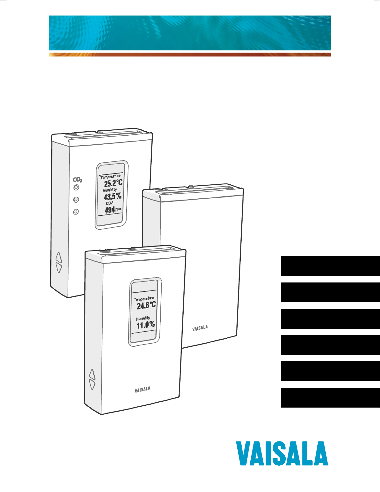
Vaisala HMW90 and GMW90 Series
Transmitters with Digital Output
English
Deutsch
Français
Português
日本語
中文
Page 2

PUBLISHED BY
Vaisala Oyj Phone (int.): +358 9 8949 1
P.O. Box 26 Fax: +358 9 8949 2227
FI-00421 Helsinki
Finland
Visit our Internet pages at www.vaisala.com.
© Vaisala 2013
No part of this manual may be reproduced, published
or publicly displayed in any form or by any means,
electronic or mechanical (including photocopying),
nor may its contents be modified, translated, adapted,
sold or disclosed to a third party without prior written
permission of the copyright holder. Translated manuals
and translated portions of multilingual documents are
based on the original English versions. In ambiguous
cases, the English versions are applicable, not the
translations.
The contents of this manual are subject to change
without prior notice.
This manual does not create any legally binding
obligations for Vaisala towards customers or end users.
All legally binding obligations and agreements are
included exclusively in the applicable supply contract
or the General Conditions of Sale and General
Conditions of Service of Vaisala.
Page 3
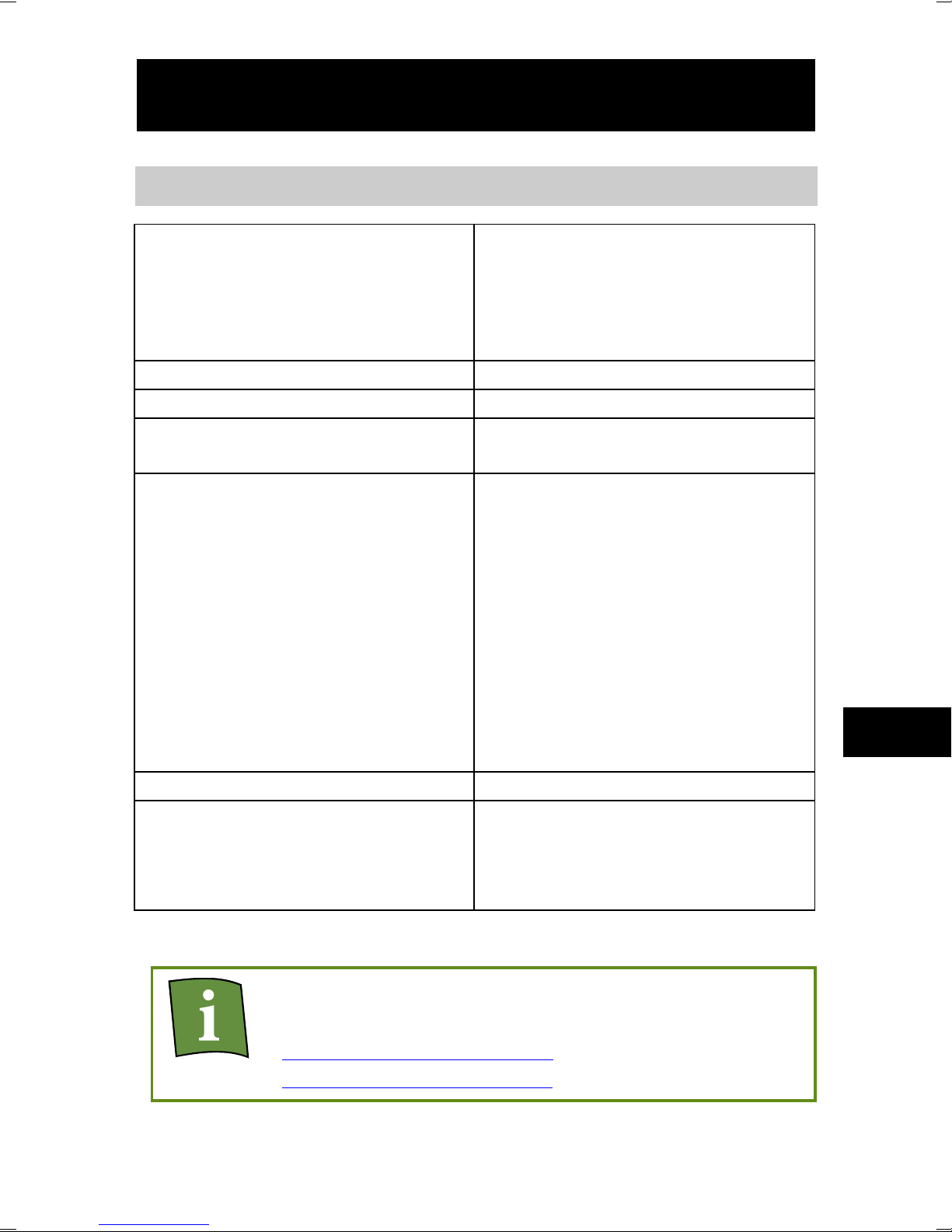
1
Measurement type
HMW95/D, HMW90*
Humidity, temperature
GMW95, GMW95D
Carbon dioxide, temperature
GMW95R, GMW95RD,
GMW90*
Carbon dioxide, humidity,
and temperature
Output type
RS-485 (isolated, 1.5 kV)
Output protocols
BACnet MS/TP, Modbus
Supply voltage
18 ... 35 VDC
24 VAC ±20 % 50/60 Hz
Current consumption
(with 120 Ω termination)
HMW90 series
Average
10 mA at 24 VDC
Maximum
30 mA at 24 VDC
Power consumption
< 0.3 W
GMW90 series
Average
20 mA at 24 VDC
Maximum
50 mA at 24 VDC
Power consumption
< 0.6 W
Dimensions (h × w × d)
132.7 × 81 × 30 mm
Setpoints for CO2 LEDs
Green 0 ... 800 ppm
Red (blinking) > 5000 ppm
ENGLISH
HMW90 and GMW90 Series Digital Models
Yellow 800 ... 1200 ppm
Red 1200 ... 5000 ppm
* Configurable model, see Order Form for options.
Datasheets and user’s guides (in English) are
available on product pages at
www.vaisala.com/hmw90
www.vaisala.com/gmw90.
EN
Page 4
2
Product Safety Information
When installing the transmitter, do not touch
exposed contacts on the component board.
When opening or closing the transmitter, avoid
damaging the transmitter electronics with the
two plastic supports on the bottom of the
mounting base.
Wire the transmitter according to the
terminal label on the mounting base.
Terminal layout depends on transmitter
model, so do not mix mounting bases from
different transmitter models.
If you connect more than one transmitter to a
single 24 VAC transformer, always connect the
phase (~) to the +Vs connector in each
transmitter.
The trimmers only turn 135 degrees each way,
less than half a rotation. Do not force the
trimmer past the stopping point.
Page 5
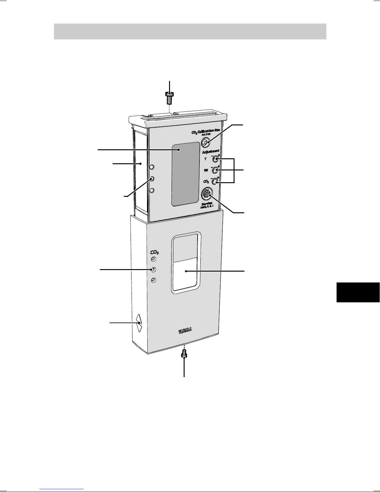
3
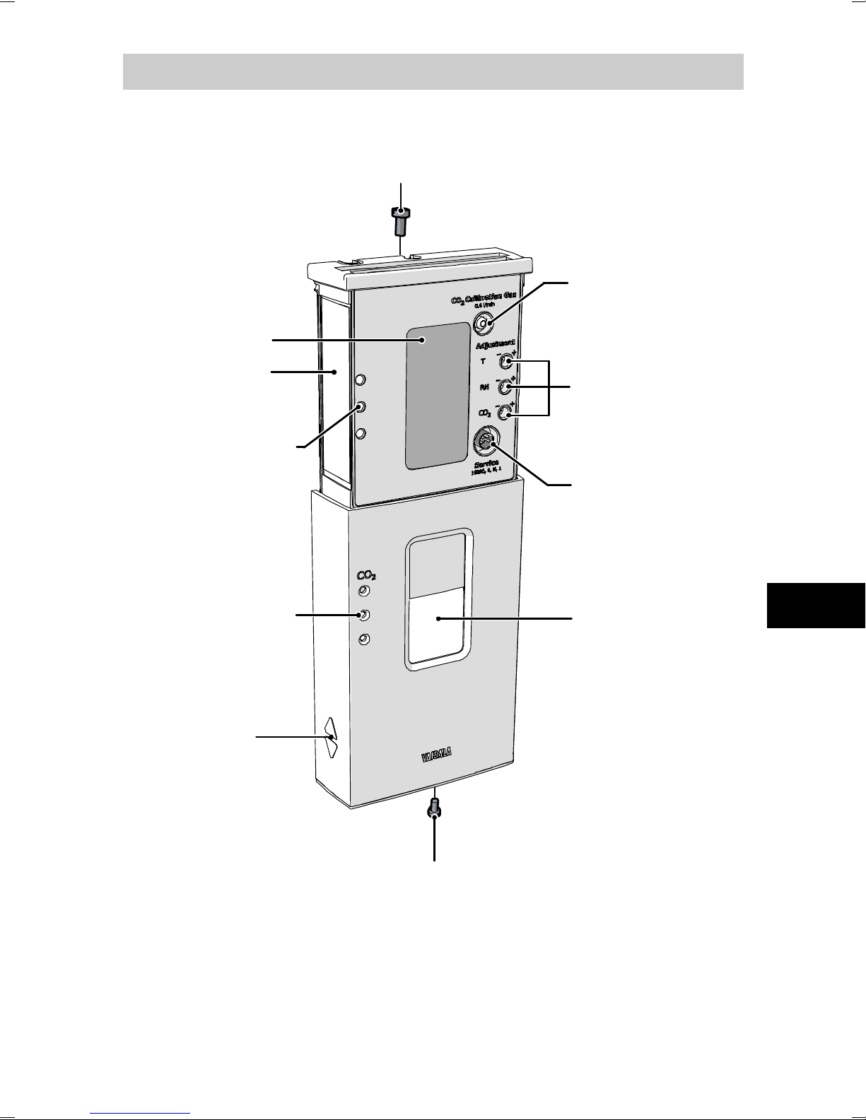
Adjustment
trimmers for
measured
parameters
Service port
Locking screw for mounting base
(not included, M3x6 recommended)
Window
for display
Grip
for slide
Display
Locking screw for slide
(not included, M3x6 recommended)
Type label
Gas inlet for
CO
2
calibration
(GMW models)
CO2 level
indicator LEDs
(GMW models)
Holes for
indicator
LEDs
Transmitter Parts - Outside
EN
Page 6
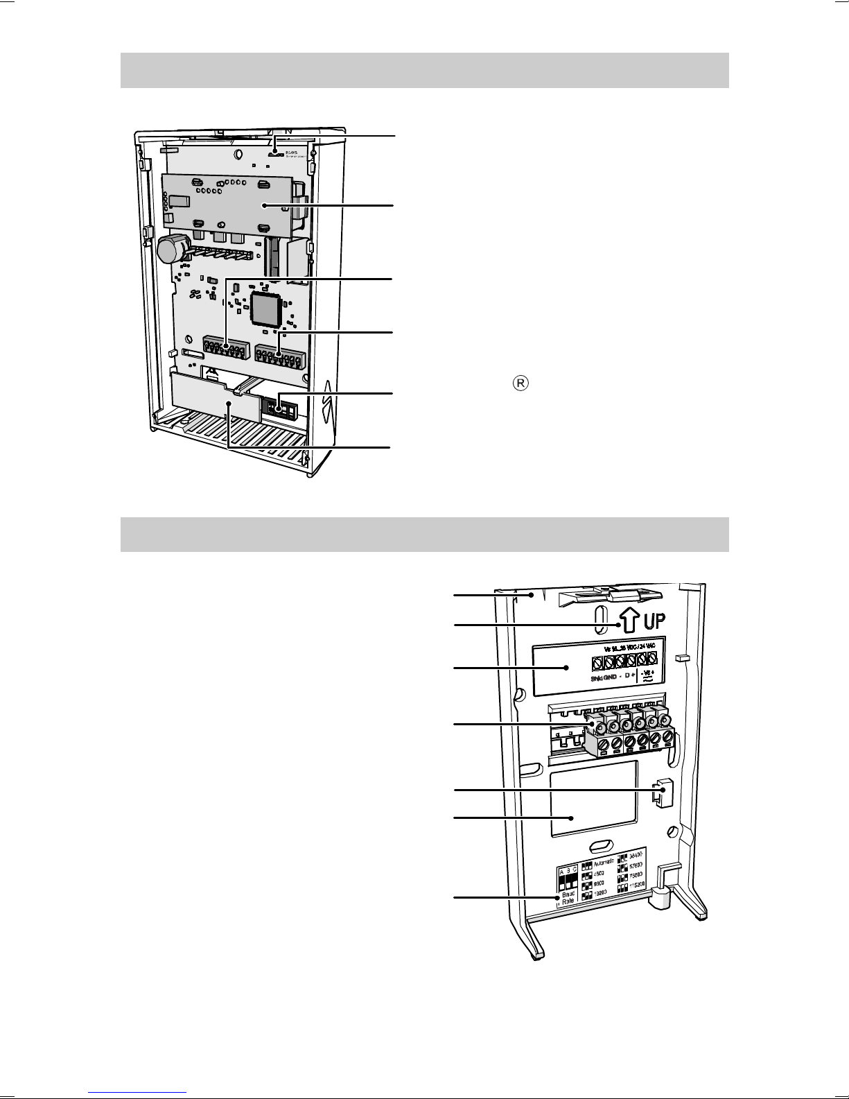
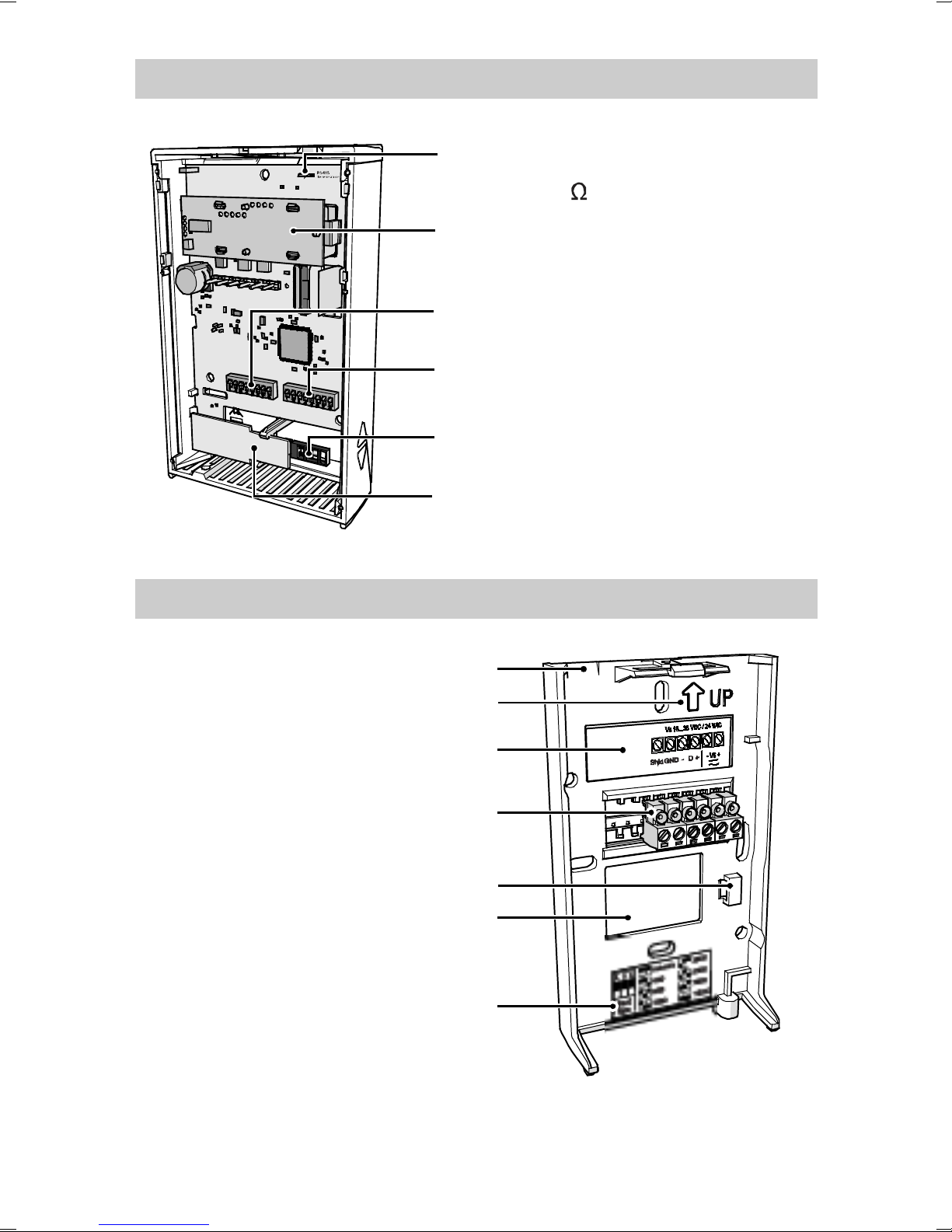
4
HTM10 module
(temperature measurement)
DIP switches for protocol
and serial line settings
HUMICAP
180R sensor
(humidity measurement)
DIP switches for
transmitter address
RS-485 termination jumper
(connects a 120 Ω resistor)
GM10 module
(CO2 measurement)
Terminal label
Orientation arrow
Opening for cable
Place for zip tie
Opening for cable
Label for RS-485 baud rate
DIP switch settings
Screw terminals
Transmitter Body
Mounting Base
Page 7
5
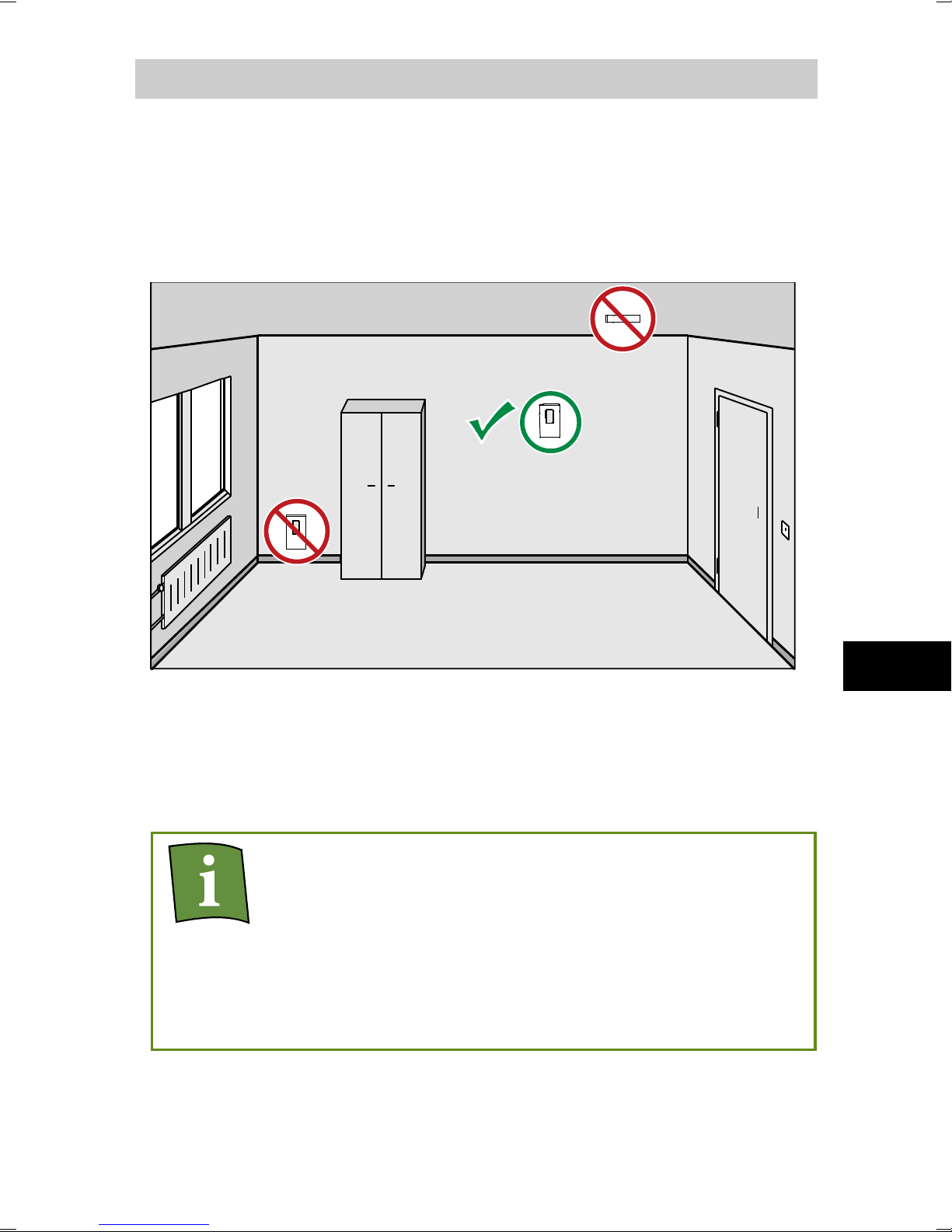
Selecting the Location
The conditions at the location should represent well the
area of interest. Do not install the transmitter on the
ceiling. Avoid placing the transmitter near heat and
moisture sources, close to the discharge of the supply
air ducts, and in direct sunlight.
Plan the routing of the cable when selecting the
location. You can bring the cable to the transmitter
from above, or from the center opening of the
mounting base.
When bringing a cable through the wall, note
that the hole may also supply air from outside
the room into the transmitter. This may affect
the measurement readings. For example,
fresh concrete binds CO
and may cause low
2
readings, especially in new buildings. Seal the
cable opening if necessary.
EN
Page 8
6
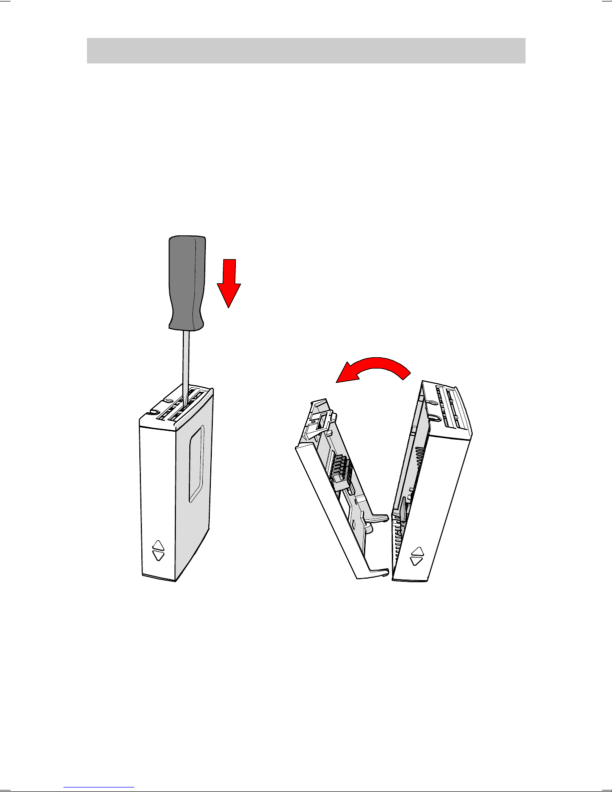
Opening and Closing
To open, use a screwdriver to push down the tab that
holds the transmitter cover and mounting base
together. Pull the mounting base away from the cover,
starting from the top.
To close, connect the bottom of the transmitter first,
and tilt the top forward to close the tab. Closing the
transmitter starts it up if power is supplied to the screw
terminals.
Page 9
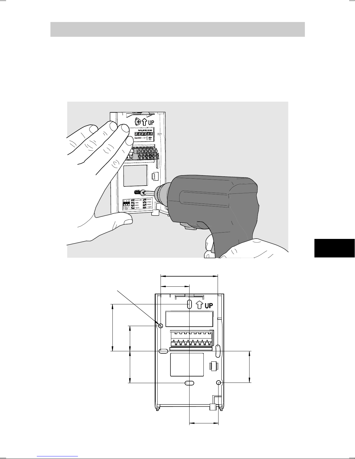
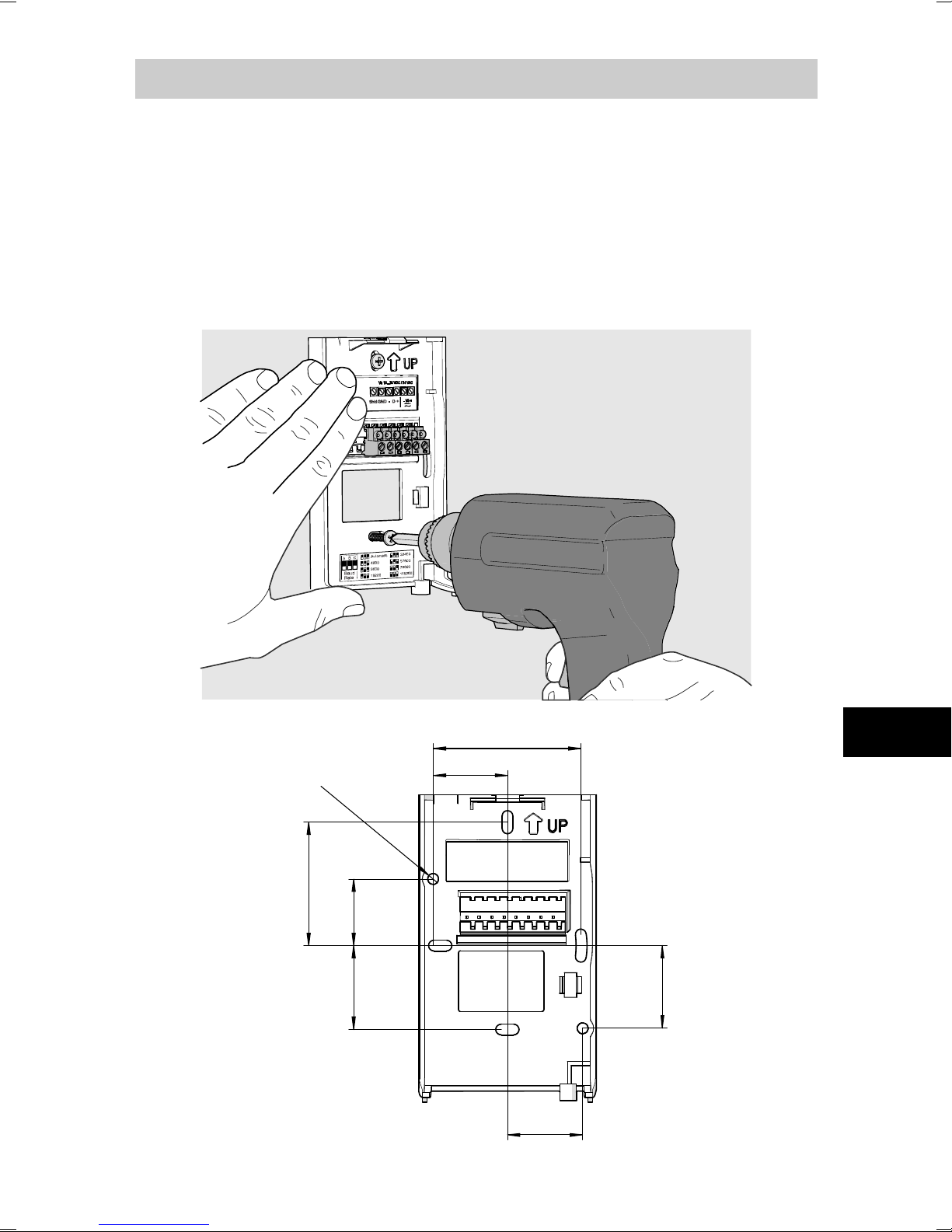
7
Proper orientation is important
50
34
27
Ø 4.4
33.5
30.5
29.8
59.5
Installing the Mounting Base
Use the mounting holes to attach the mounting base
securely. Use at least two screws (not included). The
arrow on the mounting base must point straight up
after installation.
: air
must flow through the vents on the bottom and top.
EN
Page 10
8
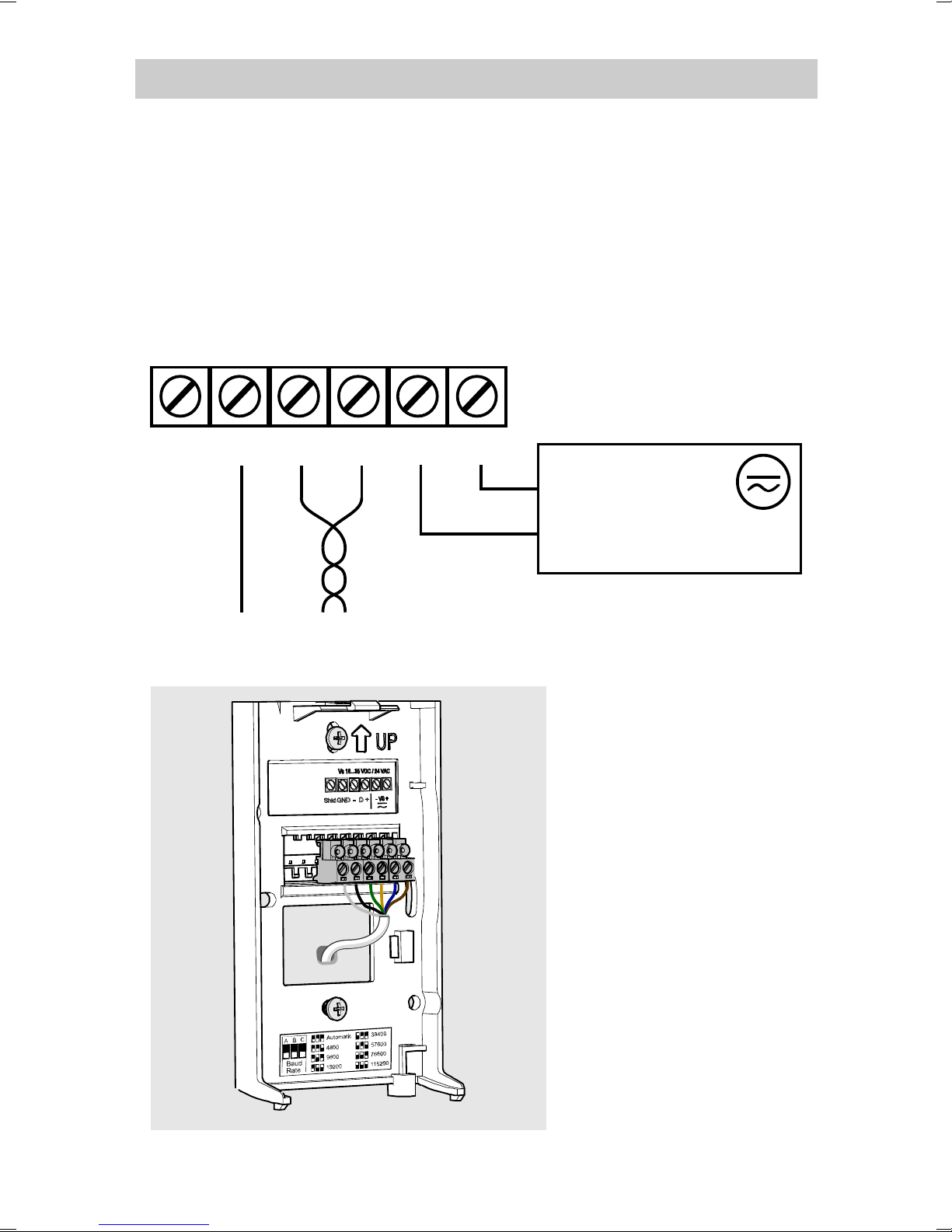
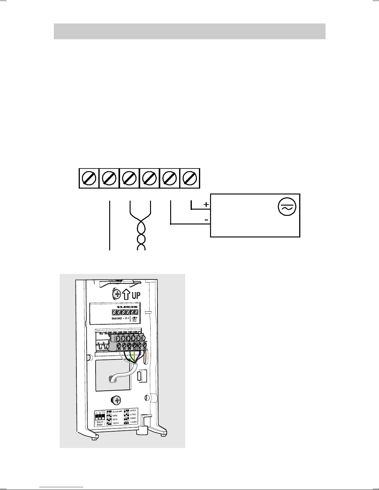
GND
Shld
D- -VsD+ +Vs
+
-
Power supply
18 ... 35 VDC
or 24 VAC ±20%
RS-485
ShldGND
Wiring
When wiring, observe the terminal labels on the
mounting base. Maximum wire size is 2 mm
The RS-485 line of the transmitter is isolated from the
power supply. A separate ground reference terminal
2
(AWG14).
(
If you are using a shielded cable, you can use the
) is provided for the RS-485 connection.
terminal to hold the exposed part of the shield. The
Shld terminal is floating (not electrically connected).
You can bring the cable
to the housing from
above or from
behind (recommended).
If you are wiring a
GMW90 series
transmitter from above,
use a < Ø 5 mm cable,
and route it from the
left side of the
mounting base.
Page 11
9
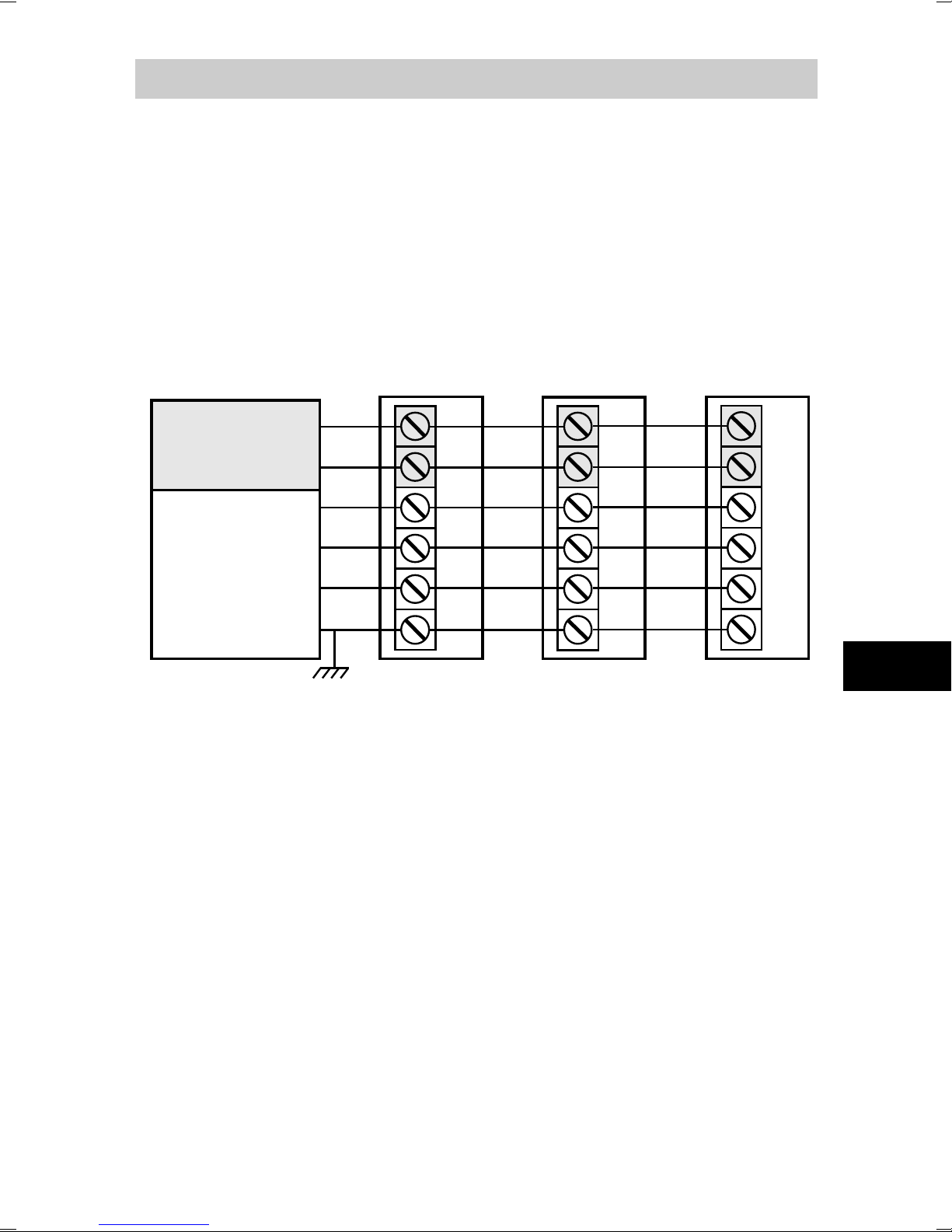
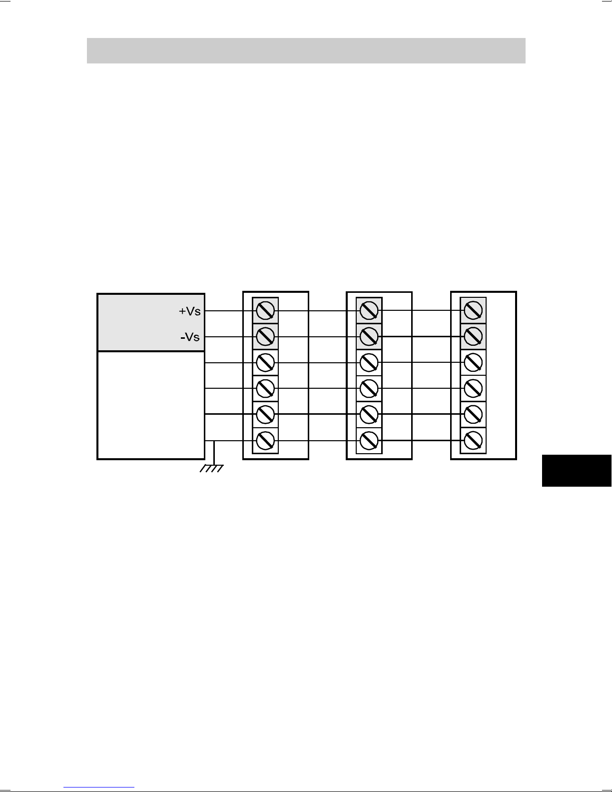
Transmitter
D-
-Vs
D+
+Vs
Shld
GND
Building controller Transmitter Transmitter
Power
supply
D-
D+
+Vs
-Vs
GND
SHIELD
RS-485:
BACnet or
Modbus
master
Connect shield on controller side
Set RS-485
termination jumper
D-
-Vs
D+
+Vs
Shld
GND
D-
-Vs
D+
+Vs
Shld
GND
Connecting Several Transmitters
Set the RS-485 termination jumper to “ON” on the
transmitter that is at the end of the line. This terminates
the line with a 120 Ω resistor. For location of the jumper,
see section Transmitter Body on page 4.
Connect the cable shield to ground on the building
controller side.
EN
Page 12
10
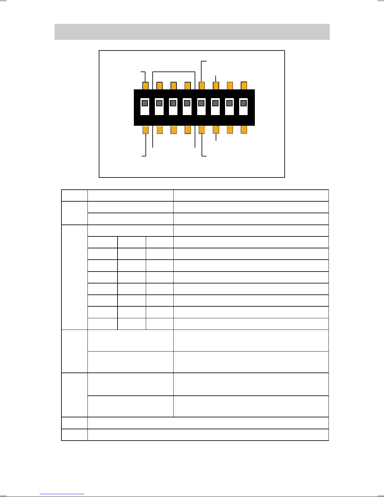
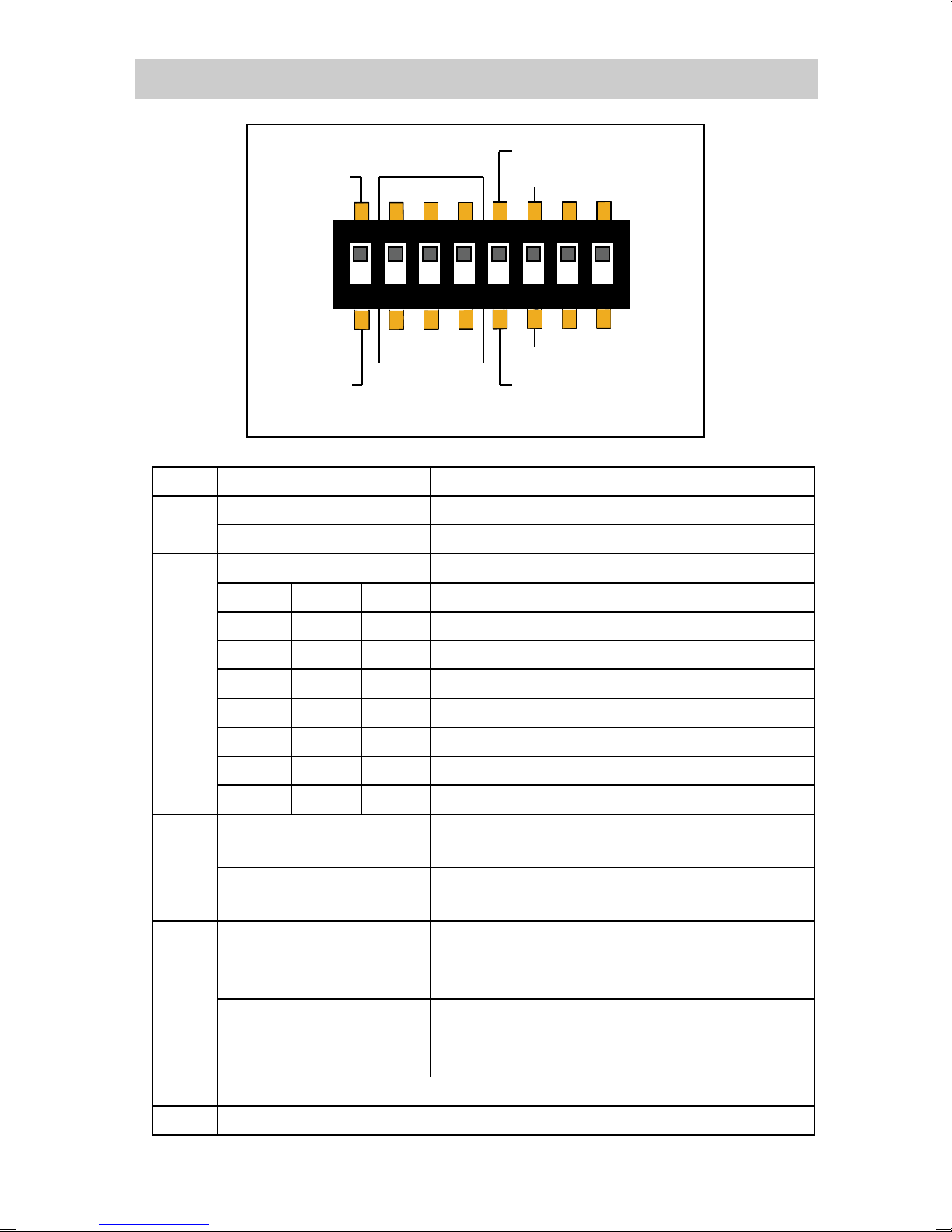
1
ON
2 3 4
5 6
7
8
Modbus
BACnet
Parity Even
A B C
Parity None
Baud
Rate
Metric
Non-Metric
DIP
Position
Setting
Modbus
Modbus protocol in use.
BACnet
BACnet protocol in use.
A B C
Serial line baud rate
Off
Off
Off
Automatic (default)
Off
Off
On
4800
Off
On
Off
9600
Off
On
On
19200
On
Off
Off
38400
On
Off
On
57600
On
On
On
115200
Parity Even
Only affects Modbus protocol.
Parity None
Only affects Modbus protocol.
Non-Metric
Only affects display and service port.
Metric
7
Not used
8
Not used
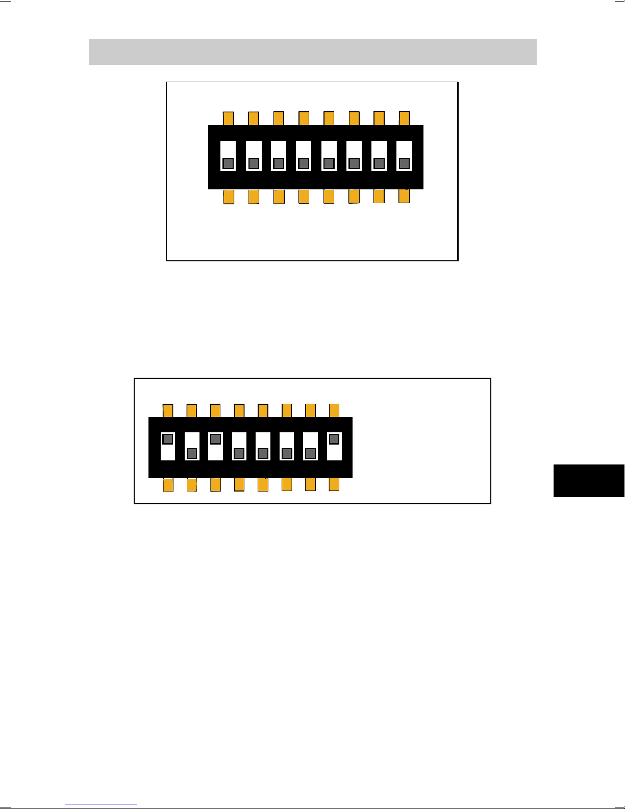
Configuration DIP Switches
1
2-4
5
6
On On Off 76800
Parity even (8E1).
Parity none (8N2).
Use non-metric units (°F).
Use metric units (°C).
Only affects display and service port.
Page 13
11
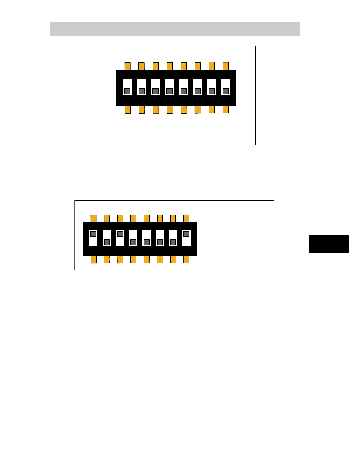
1
2 3 4
5 6
7
8
128 64 32 16 8 4 2 1
Address
(Binary Weighting)
ON
Address Binary Weighting
1
2 3 4
5 6
7
8
128 64 32 16 8 4 2 1
ON
Binary: 10100001
Decimal: 161
(128 + 32 + 1)
=
Address DIP Switches
Dip switches marked
the MAC address of the transmitter. The address is
encoded in eight bit binary form, with each numbered
switch representing a single bit. For example:
set
Addressing with BACnet Protocol
BACnet MS/TP MAC address range is 0 … 255. The
address determines if the transmitter is a master or
slave:
EN
- Address range 0 ... 127: transmitter is a master.
- Address range 128 ... 255: transmitter is a slave.
Addressing with Modbus Protocol
Transmitter is always a Modbus slave. MAC address
range for Modbus slaves is 1 … 247.
Page 14

12
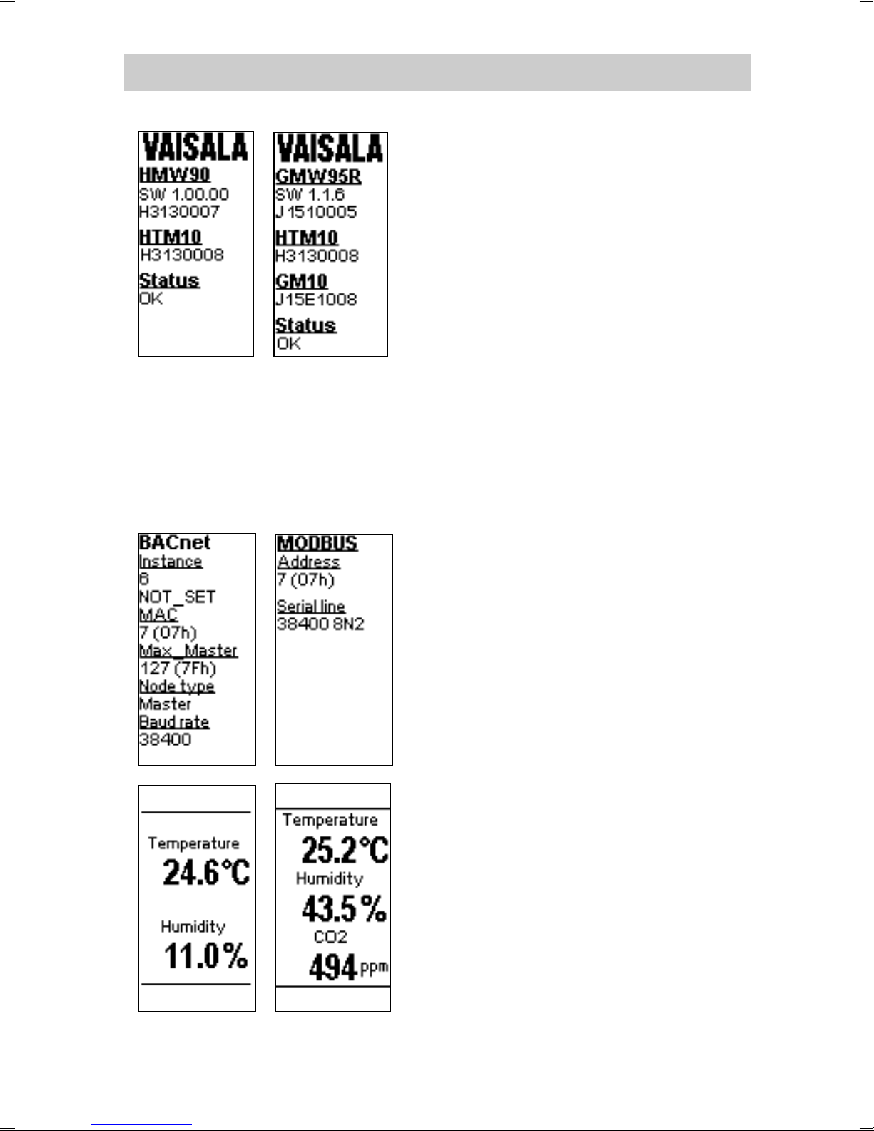
Transmitter Startup
When the transmitter is
powered on, it displays a
sequence of information
screens. The screens are
shown for a few seconds each.
The first screen identifies the
transmitter and the connected
measurement modules,
and shows if the transmitter
is operating normally
(status OK) or if there is an
error (status ERROR).
The second screen shows
configuration information that
is relevant to the selected
communication protocol
(BACnet or Modbus)
After the startup screens the
transmitter shows the
measurement screen. It shows
the measured parameters and
currently active indicators.
It is normal for CO
2
measurement to read 0 ppm
for a few seconds after the
startup.
Page 15
13
Trimmer Adjustment (RH and T)
Before starting the adjustment, compare
the reading of the transmitter to a
calibrated reference instrument so you
know how much adjustment is needed.
You can use, for example, the HM70 handheld humidity and temperature meter.
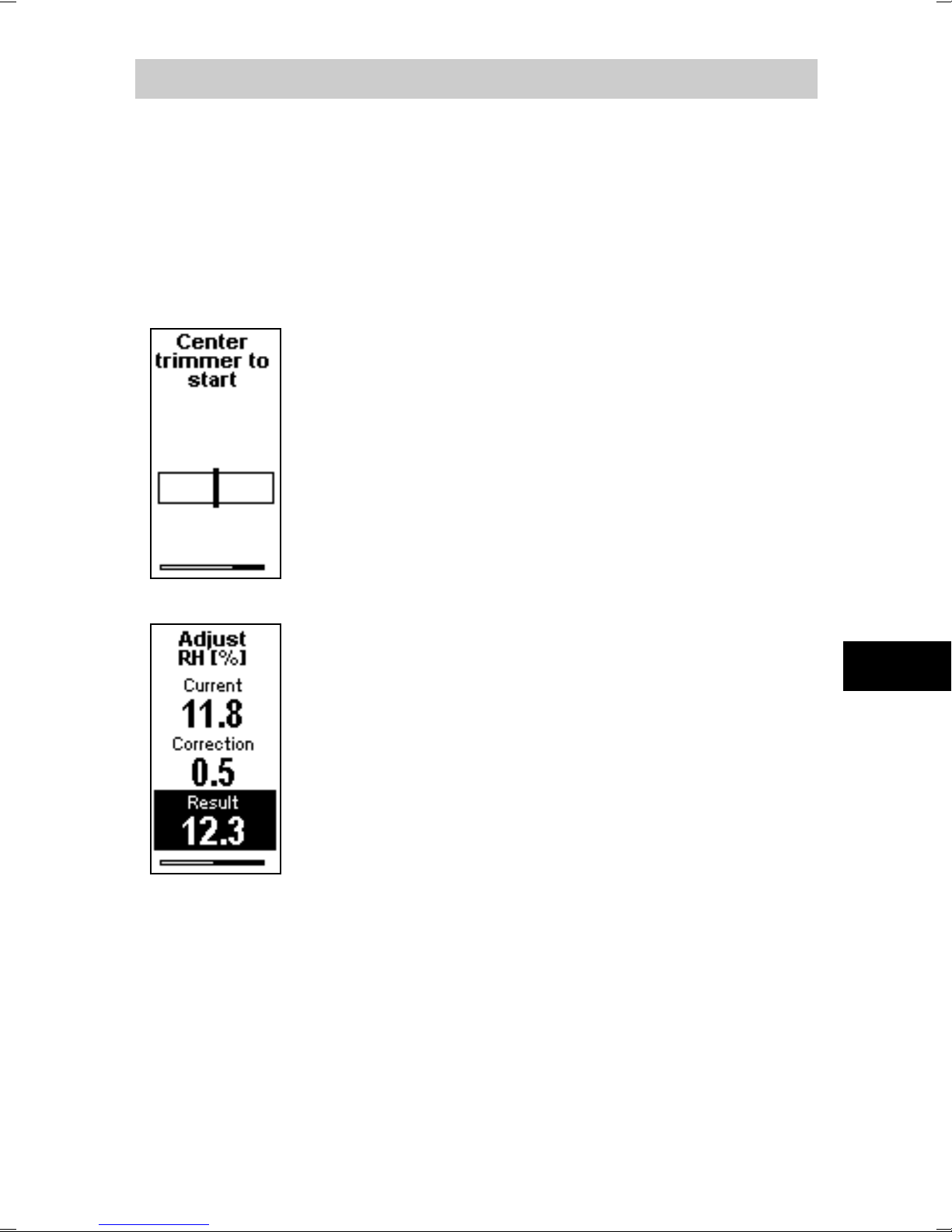
To enter the adjustment screen, select the
parameter to adjust, and rotate the RH or T
trimmer slightly during normal
measurement. If the trimmer is not
centered, you see the trimmer centering
screen first. Simply turn the trimmer to the
center and wait for the progress bar to
complete.
In the adjustment screen, turn the trimmer
to set the desired correction. To commit the
EN
change, stop turning the trimmer and wait.
If you wish to apply a greater correction
than allowed by the trimmer in a single
adjustment, re-enter the adjustment screen
and apply a new correction. Corrections
applied using the trimmers are cumulative.
Page 16
14
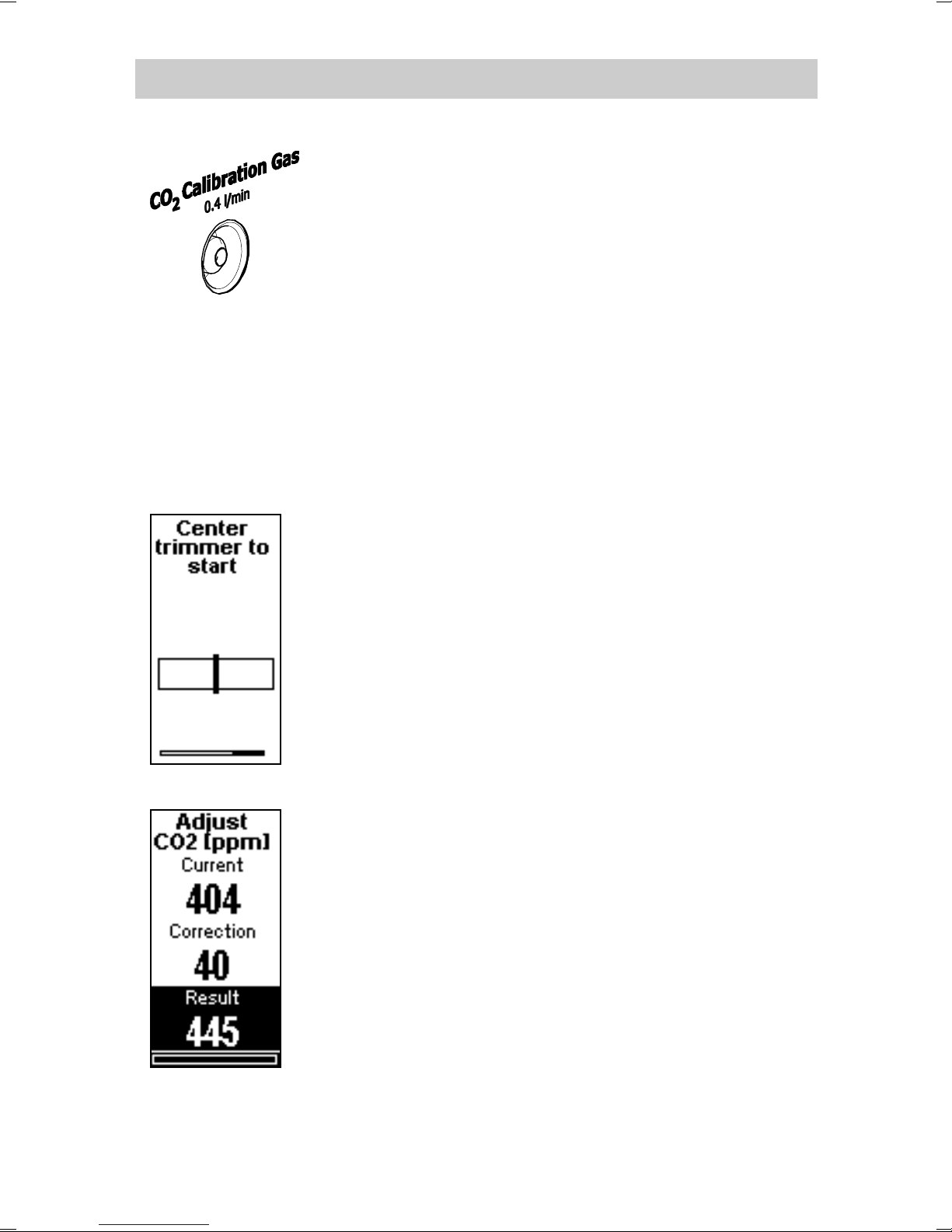
Trimmer Adjustment (CO2)
Transmitter models with CO
measurement
2
have an inlet for calibration gas. Supply the
calibration gas with a known concentration
(for example, 1000 ppm) to this inlet using
a 3 mm inner diameter silicone tube and a
0.4 l/min flow.
Turn on the gas flow and wait for three
minutes for measurement to stabilize.
If you are adjusting without calibration gas,
avoid breathing on the transmitter.
You should only adjust the transmitter
when the CO
Rotate the CO
reading is stable.
2
trimmer slightly during
2
normal measurement. If the trimmer is not
centered, you see the trimmer centering
screen first. Simply turn the trimmer to the
center and wait for the progress bar to
complete.
In the adjustment screen, turn the trimmer
to set the desired correction. To commit
the change, stop turning the trimmer and
wait. The transmitter will show with a text
screen if the adjustment was successful, or
failed due to an unstable CO
reading.
2
As with the RH and T adjustment, repeated
trimmer adjustments are cumulative. Wait
for a few minutes between adjustments to
allow the CO
reading to stabilize.
2
Page 17
15
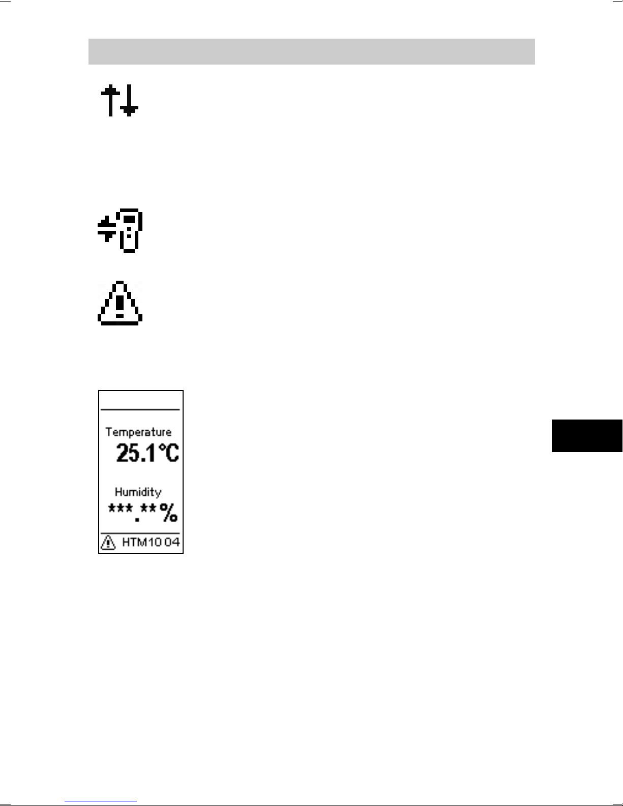
Communication arrows
MI70 connection indicator
Alert indicator and error text
Indicators
Shown on top right of the screen. Down
arrow is shown when transmitter detects
valid traffic on the RS-458 line. Up arrow is
shown when transmitter is transmitting to the
RS-485 line.
Shown on top left of the screen if an MI70
Indicator is connected to the service port.
Shown on bottom of screen if there is an
error active. Followed by an error text. If
more than one error is active, the error text
will cycle through the errors.
When the alert indicator and error text are
shown, typically one or more measurement
readings are replaced with stars. This means
these measurements are affected by the
error.
EN
Page 18
16
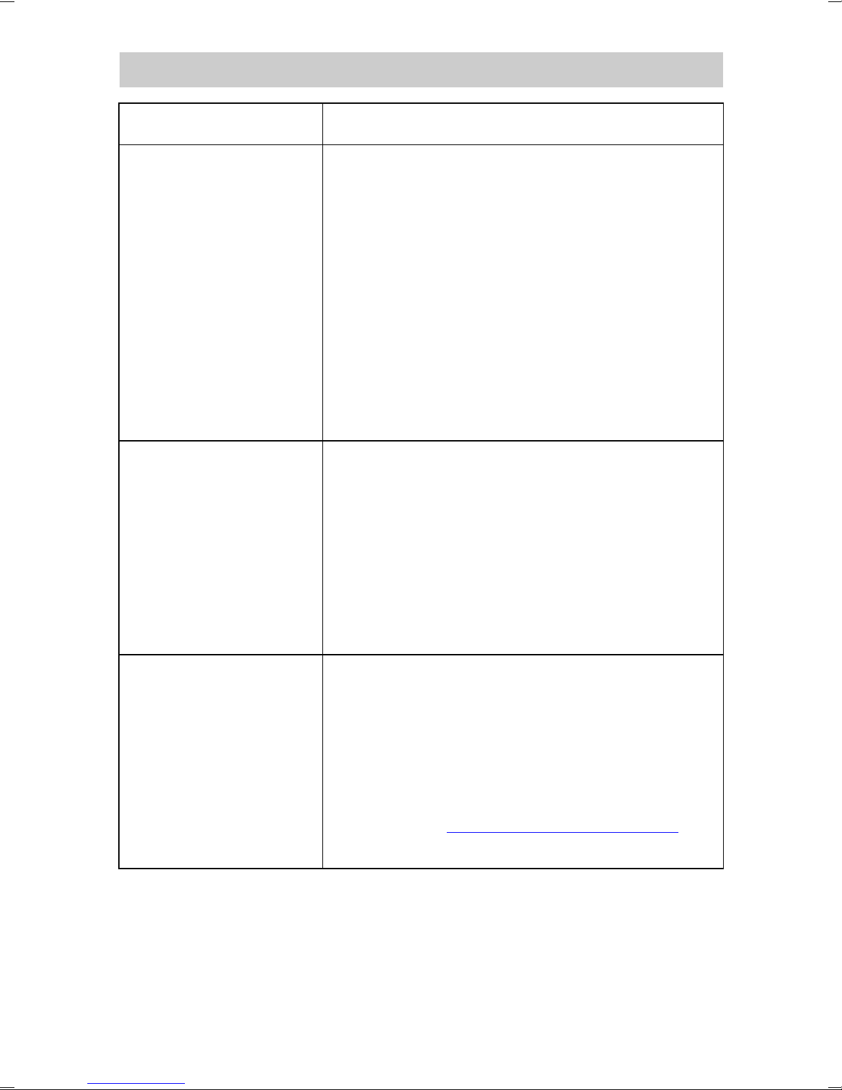
Error Type
Cause and Possible Solution
Errors
HTM10 error Problem with HTM10 module.
- Check that the module sits firmly
in place. Remove and reconnect.
- Check for missing or damaged
HUMICAP® sensor.
- Check for condensation on the
HUMICAP® sensor. Wait for the
sensor to dry out.
- Replace the module if unable to
remove the problem.
GM10 error Problem with GM10 module.
- Check that the module sits firmly
in place. Remove and reconnect.
- Check that supply voltage is in
range.
- Replace the module if unable to
remove the problem.
Internal error Internal problem with the transmitter.
- Restart the transmitter.
- Restore the factory settings using
service port if reset does not
help.
- Contact helpdesk@vaisala.com if
unable to remove the problem.
Page 19
17
Art der Messung
HMW95/D, HMW90*
Feuchte, Temperatur
GMW95, GMW95D
Kohlendioxid, Temperatur
GMW95R, GMW95RD,
GMW90*
Kohlendioxid, Feuchte und
Temperatur
Ausgangstyp
RS-485 (isoliert, 1,5 kV)
Ausgabeprotokolle
BACnet MS/TP, Modbus
Versorgungsspannung
18 ... 35 V DC
24 V AC ±20 %, 50/60 Hz
Stromaufnahme
widerstand)
Baureihe HMW90
Durchschnitt
10 mA bei 24 V DC
Maximum
30 mA bei 24 V DC
Stromverbrauch
< 0,3 W
Baureihe GMW90
Durchschnitt
20 mA à 24 VCC
Maximum
50 mA à 24 VCC
Stromverbrauch
< 0,6 W
Abmessungen (H × B × T)
132,7 × 81 × 30 mm
Schaltschwellen
Grün 0 ... 800 ppm
Rot (blinkend) > 5000 ppm
DEUTSCH
Digitalmodelle HMW90 und GMW90
(mit 120-Ω-Abschluss-
für CO2-LEDs
* Konfigurierbares Modell, Optionen siehe Bestellformular.
Gelb 800 ... 1200 ppm
Rot 1200 ... 5000 ppm
DE
Datenblätter und Benutzerhandbücher
(in Englisch) sind auf den Produktseiten unter
www.vaisala.com/hmw90
www.vaisala.com/gmw90 verfügbar.
Page 20
18
Produktsicherheitsinformationen
Beim Einbauen des Messwertgebers
keine freiliegenden Kontakte auf der
Komponentenplatine berühren.
Beim Öffnen oder Schließen des
Messwertgebers die Messwertgeberelektronik
nicht mit den beiden Kunststoffstützen unten
auf der Montageplatte beschädigen.
Messwertgeber unter Beachtung des
Anschlussetiketts auf der Montageplatte
verkabeln. Die Anschlussbelegung ist
vom Messwertgebermodell abhängig,
die Montageplatten unterschiedlicher
Messwertgebermodelle dürfen deshalb
nicht vermischt werden.
Wenn Sie mehr als einen Messwertgeber
an einen einzelnen 24-V-AC-Transformator
anschließen, müssen Sie die Phase (~) mit
dem +Vs-Anschluss der Messwertgeber
verbinden.
Die Trimmer lassen sich nur um 135 Grad nach
rechts bzw. links drehen (weniger als eine
halbe Drehung). Drehen Sie die Trimmer nicht
über den Anschlag hinaus.
Page 21
19
Einstellungstrimmer für
gemessene
Parameter
Serviceschnittstelle
Sicherungsschraube für Montageplatte
(nicht enthalten, empfohlen: M3x6)
Anzeigefenster
Fingerauflage
zum Auf-/
Zuschieben
Anzeige
Sicherungsschraube für Schieber
(nicht enthalten, empfohlen: M3x6)
Typenschild
Gaseinlass für
CO
2
-Kalibrierung
(GMW-Modelle)
LEDs für CO
2
Konzentration
(GMW-Modelle)
Bohrungen
für LEDs
Messwertgeberteile – Außen
DE
Page 22
20
HTM10-Modul
(Temperaturmessung)
DIP-Schalter für Protokoll- und
serielle Leitungseinstellungen
HUMICAP® 180R-Sensor
(Feuchtemessung)
DIP-Schalter für
Messwertgeberadresse
RS-485-Abschlusssteckbrücke (verbindet
einen 120-
-Widerstand)
GM10-Modul
(CO
2
-Messung)
Terminalbeschriftung
Ausrichtungspfeil
Kabeldurchführung
Position für Kabelbinder
Kabeldurchführung
Etikett mit
DIP-Schaltereinstellungen
für RS-485-Baudrate
Schraubklemmen
Messwertgebergehäuse
Montageplatte
Page 23

21
Auswählen des Standorts
Die Bedingungen am Standort sollten den relevanten
Bereich repräsentieren. Messwertgeber nicht an der
Decke montieren. Messwertgeber nicht in der Nähe von
Wärme- oder Feuchtigkeitsquellen, neben dem Auslass
von Luftleitungen oder in direktem Sonnenlicht
platzieren.
Planen Sie bei der Auswahl des Standorts die
Verlegung des Kabels. Sie können das Kabel von oben
oder durch die zentrale Öffnung der Montageplatte
zum Messwertgeber führen.
Beachten Sie, dass bei einer Kabelverlegung
durch ein Loch in der Wand Luft von der
anderen Seite der Wand in den
Messwertgeber eindringen kann. Dies kann die
Messwerte beeinflussen. Frischer Beton bindet
beispielsweise CO
und kann zu niedrigen
2
Messwerten führen, insbesondere in
Neubauten. Dichten Sie die Kabelöffnung ab,
wenn dies erforderlich ist.
DE
Page 24

22
Öffnen und Schließen
Drücken Sie zum Öffnen des Messwertgebers mit
einem Schraubendreher die Nase nach unten, die die
Abdeckung des Messwertgebers an der Montageplatte
hält. Ziehen Sie die Montageplatte von der Abdeckung,
beginnend an der Oberkante.
Verbinden Sie zum Schließen des Messwertgebers
zunächst dessen Unterkante und neigen Sie dann die
Oberkante zur Montageplatte, bis die Nase einrastet.
Der Messwertgeber wird beim Schließen gestartet,
wenn Spannung an den Schraubklemmen anliegt.
Page 25
23
Die richtige Ausrichtung ist wichtig
50
34
27
Ø 4,4
33,5
30,5
29,8
59,5
Montieren der Montageplatte
Montagebohrungen verwenden, um die Montageplatte
sicher zu befestigen. Mindestens zwei Schrauben
verwenden (nicht im Lieferumfang). Der Pfeil auf der
Montageplatte muss nach der Montage gerade nach
oben zeigen.
:
Die Luft muss durch die Öffnungen im Boden und auf
der Oberseite strömen können.
DE
Page 26
24
GND
Shld
D- -VsD+ +Vs
Versorgungsspannung
18 bis 35 V DC
oder 24 V AC ±20 %
RS-485
Shld GND
Verdrahten
Beachten Sie beim Verdrahten die Anschlussetiketten
auf der Montageplatte. Der maximale Aderquerschnitt
beträgt 2 mm
Messwertgebers ist gegenüber der Stromversorgung
2
(AWG14). Die RS-485-Leitung des
isoliert. Eine separate Erdklemme (
) für die
RS-485-Verbindung ist vorhanden.
Wenn Sie ein abgeschirmtes Kabel verwenden, können
Sie die
-Klemme zur Aufnahme des freiliegenden
Teils der Abschirmung verwenden. Die „Shld“-Klemme
ist ungeerdet (elektrisch nicht verbunden).
Sie können das Kabel
von oben oder hinten
(empfohlen) in das
Gehäuse führen.
Wenn Sie einen
Messwertgeber der
Baureihe GMW90 von
oben verdrahten,
verwenden Sie ein Kabel
mit einem Durchmesser
von < 5 mm und verlegen
Sie es von der linken Seite
der Montageplatte.
Page 27
25
Messwertgeber
D-
-Vs
D+
+Vs
Shld
GND
Gebäudecontroller Messwertgeber Messwertgeber
Stromversorgung
D-
D+
GND
SHIELD
RS-485:
BACnet- oder
Modbus-Master
Kabelschutz auf Controllerseite anschließen
RS-485-Abschlusssteck-
brücke setzen
D-
-Vs
D+
+Vs
Shld
GND
D-
-Vs
D+
+Vs
Shld
GND
Verbinden mehrerer Messwertgeber
Setzen Sie die RS-485-Abschlusssteckbrücke
am letzten Messwertgeber der Reihe auf „ON“.
Dadurch wird die Reihe mit einem 120-Ω-Widerstand
abgeschlossen. Informationen zur Position der
Steckbrücke finden Sie im Abschnitt
Messwertgebergehäuse Seite 20.
Verbinden Sie die Kabelabschirmung auf
Gebäudecontrollerseite mit Erde.
DE
Page 28
26
1
ON
2 3 4
5 6
7
8
Modbus
BACnet
Parity Even
A B C
Parity None
Baud
Rate
Metric
Non-Metric
DIP
Position
Einstellung
Modbus
Modbus-Protokoll wird verwendet.
BACnet
BACnet-Protokoll wird verwendet.
2-4
A B C
Baudrate der seriellen Leitung
Off
Off
Off
Automatisch (Standard)
Off
Off
On
4800
Off
On
Off
9600
Off
On
On
19200
On
Off
Off
38400
On
Off
On
57600
On
On
Off
76800
On
On
On
115200
Parity Even
Parity None
Betrifft nur das Modbus-Protokoll.
Non-Metric
Metric
und die Serviceschnittstelle.
7
Nicht verwendet
8
Nicht verwendet
DIP-Schalter für die Konfiguration
1
5
6
Gerade Parität (8E1).
Betrifft nur das Modbus-Protokoll.
Keine Parität (8N2).
Nicht-metrische Einheiten (°F)
verwenden. Betrifft nur die Anzeige
und die Serviceschnittstelle.
Metrische Einheiten (°C)
verwenden. Betrifft nur die Anzeige
Page 29
27
1
2 3 4
5 6
7
8
128 64 32 16 8 4 2 1
Address
(Binary Weighting)
ON
Address Binary Weighting
1
2 3 4
5 6
7
8
128 64 32 16 8 4 2 1
ON
Binär: 10100001
Dezimal: 161
(128 + 32 + 1)
=
DIP-Schalter für Adresse
Die mit
DIP-Schalter legen die MAC-Adresse des
Messwertgebers fest. Die Adresse wird als binärer
8-Bit-Wert codiert. Jeder der nummerierten Schalter
repräsentiert ein Bit. Beispiel:
beschrifteten
Adressierung mit dem BACnet-Protokoll
Der MAC-Adressbereich für BACnet MS/TP liegt
zwischen 0 und 255. Die Adresse bestimmt,
DE
ob der Messwertgeber Master oder Slave ist:
- Adressbereich 0 bis 127: Messwertgeber ist ein Master.
- Adressbereich 128 bis 255: Messwertgeber ist ein Slave.
Adressierung mit dem Modbus-Protokoll
Der Messwertgeber ist immer ein Modbus-Slave.
Der MAC-Adressbereich für Modbus-Slaves reicht
von 1 bis 247.
Page 30
28
Messwertgeberstart
Beim Einschalten des
Messwertgebers wird eine
Folge von Informationsbildschirmen angezeigt.
Die einzelnen Bildschirme
werden jeweils für einige
Sekunden angezeigt.
Der erste Bildschirm
identifiziert den Messwertgeber und die angeschlossenen Messmodule und gibt
an, ob der Messwertgeber
normal arbeitet (Status OK)
oder ob ein Fehler vorliegt
(Status ERROR).
Der zweite Bildschirm zeigt
Konfigurationsinformationen
an, die für das ausgewählte
Kommunikationsprotokoll
relevant sind (BACnet oder
Modbus)
Nach den Startbildschirmen
zeigt der Messwertgeber den
Messungsbildschirm an.
Dieser enthält die gemessenen Parameter und die
derzeit aktiven Indikatoren.
Es ist normal, dass der
Messwert für CO
einige
2
Sekunden nach dem Start bei
0 ppm liegt.
Page 31

29
Trimmereinstellung (rF und T)
Vergleichen Sie den Messwert des
Messwertgebers vor Beginn der
Einstellung mit einem kalibrierten
Referenzinstrument, um zu ermitteln,
welche Einstellung erforderlich ist.
Sie können beispielsweise das
Handmessgerät HM70 für Feuchte
und Temperatur verwenden
Wählen Sie den einzustellenden
Parameter und drehen Sie den rF- oder
T-Trimmer im normalen Messbetrieb
leicht, um zum Einstellungsbildschirm
zu gelangen. Wenn der Trimmer nicht
zentriert ist, wird zunächst der TrimmerZentrierbildschirm angezeigt. Drehen
Sie den Trimmer zum Mittelpunkt,
und warten Sie, bis die Fortschrittsleiste
den Abschluss der Operation meldet.
Drehen Sie den Trimmer im Einstellungsbildschirm, um die gewünschte
Korrektur einzustellen. Die Änderung
wird bestätigt, indem Sie das Drehen
des Trimmers beenden und warten.
Wenn Sie eine größere Korrektur
zuweisen wollen, als der Trimmer bei
einer einzelnen Einstellungsoperation
erlaubt, rufen Sie den Einstellungsbildschirm erneut auf, um eine weitere
DE
Korrektur zuzuweisen. Dem Trimmer
zugewiesene Korrekturen gelten
kumulativ.
Page 32

30
dürfen den Messwertgeber erst einstellen,
Trimmer zum Mittelpunkt, und warten Sie, bis
Drehen Sie den Trimmer im Einstellungs-
Trimmereinstellung (CO2)
Messwertgebermodelle mit CO2-Messung
besitzen einen Einlass für Kalibriergas.
Führen Sie diesem Einlass Kalibriergas mit
bekannter Konzentration (z. B. 1000 ppm)
über einen Silikonschlauch mit einem
Innendurchmesser von 3 mm und einer
Durchflussrate von 0,4 l/min zu.
Schalten Sie den Gasstrom ein und warten
Sie drei Minuten, bis sich der Messwert
stabilisiert hat. Wenn Sie die Einstellung ohne
Kalibriergas vornehmen, vermeiden Sie das
Atmen in der Nähe des Messwertgebers.
Sie
wenn der CO2-Messwert stabil ist.
Drehen Sie den CO2-Trimmer im normalen
Messbetrieb leicht. Wenn der Trimmer nicht
zentriert ist, wird zunächst der TrimmerZentrierbildschirm angezeigt. Drehen Sie den
die Fortschrittsleiste den Abschluss
der Operation meldet.
bildschirm, um die gewünschte Korrektur
einzustellen. Die Änderung wird bestätigt,
indem Sie das Drehen des Trimmers beenden
und warten. Der Messwertgeber zeigt einen
Textbildschirm an, wenn die Einstellung
erfolgreich war oder aufgrund eines
instabilen CO
-Messwerts fehlgeschlagen ist.
2
Bei der Einstellung für rF und T sind
wiederholte Trimmereinstellungen kumulativ.
Warten Sie einige Minuten zwischen den
Messungen, damit sich der CO
stabilisieren kann.
-Messwert
2
Page 33

31
Kommunikationspfeile
MI70-Verbindungsindikator
Warnungsindikator und Fehlertext
Indikatoren
Wird oben rechts auf dem Bildschirm
angezeigt. Der Abwärtspfeil wird
angezeigt, wenn der Messwertgeber
gültigen Datenverkehr auf der RS-458Leitung feststellt. Der Aufwärtspfeil wird
angezeigt, wenn der Messwertgeber auf
der RS-485-Leitung überträgt.
Wird oben links auf dem Bildschirm
angezeigt, wenn ein MI70-Indikator mit
der Serviceschnittstelle verbunden ist.
Wird unten auf dem Bildschirm angezeigt,
wenn ein Fehler aktiv ist. Es folgt ein
Fehlertext. Ist mehr als ein Fehler aktiv,
werden die zugehörigen Fehlertexte in
einer Schleife angezeigt.
Werden Warnungsindikator und
Fehlertext angezeigt, wurde
normalerweise mindestens ein Messwert
durch Sternchen ersetzt. Dies bedeutet,
dass die betreffenden Messwerte von
dem Fehler betroffen sind.
DE
Page 34

32
Fehlertyp
Ursache und mögliche Lösung
Fehler
HTM10Fehler
GM10Fehler
Problem mit dem HTM10-Modul.
- Prüfen Sie, ob das Modul fest sitzt.
Bauen Sie es aus und schließen Sie es
wieder an.
- Prüfen Sie auf einen fehlenden oder
schadhaften HUMICAP®-Sensor.
- Prüfen Sie auf Kondensation auf dem
HUMICAP®-Sensor. Warten Sie, bis der
Sensor abgetrocknet ist.
- Tauschen Sie das Modul aus, wenn Sie
das Problem nicht beheben können.
Problem mit dem GM10-Modul.
- Prüfen Sie, ob das Modul fest sitzt.
Bauen Sie es aus und schließen Sie es
wieder an.
Interner
Fehler
- Prüfen Sie, ob die Speisespannung im
zulässigen Bereich liegt.
- Tauschen Sie das Modul aus, wenn Sie
das Problem nicht beheben können.
Internes Problem mit dem Messwertgeber.
- Starten Sie den Messwertgeber neu.
- Stellen Sie die Werkseinstellungen über
die Serviceschnittstelle wieder her, wenn
das Problem nicht durch eine
Zurücksetzung behoben werden kann.
- Kontaktieren Sie helpdesk@vaisala.com,
wenn Sie das Problem nicht beheben
können.
Page 35

33
Type de mesure
HMW95/D, HMW90*
Humidité, température
GMW95, GMW95D
Dioxyde de carbone,
température
GMW95R, GMW95RD,
Dioxyde de carbone,
Type de sortie
RS-485 (isolé, 1,5 kV)
Protocoles de sortie
BACnet MS/TP, Modbus
Tension d’alimentation
18 ... 35 VCC
24 VCA ±20 % 50/60 Hz
Consommation électrique
(avec résistance de 120 Ω)
Série HMW90
Moyenne
10 mA à 24 VCC
Maximum
30 mA à 24 VCC
Consommation
électrique
< 0,3 W
Série GMW90
Moyenne
20 mA à 24 VCC
Maximum
50 mA à 24 VCC
Consommation
électrique
< 0,6 W
Dimensions (h × l × p)
132,7 × 81 × 30 mm
Points de réglage pour
Vert 0 ... 800 ppm
> 5 000 ppm
FRANÇAIS
Séries HMW90 et GMW90 –
Modèles numériques
GMW90*
humidité et température
FR
les DEL de CO2
* Modèle configurable, reportez-vous au bon de
commande pour les options.
Jaune 800 ... 1 200 ppm
Rouge 1 200 ... 5 000 ppm
Rouge (clignotant)
Page 36

34
Informations sur la sécurité du produit
Lors de l'installation du transmetteur, ne touchez
pas les contacts visibles sur le panneau de
contact.
Lors de l'ouverture ou de la fermeture du transmetteur, évitez d'endommager les composants
électroniques du transmetteur avec les deux
supports en plastique situés sur le fond du socle.
Branchez le transmetteur conformément
à l'étiquette des bornes apposée sur le socle.
La disposition des bornes dépend du modèle
de transmetteur ; vous ne devez donc pas
échanger les socles entre différents modèles
de transmetteurs.
Si vous raccordez plusieurs transmetteurs à un
seul transformateur 24 VCA, vous devez toujours
raccorder la phase (~) au connecteur +Vs de
chaque transmetteur.
Les condensateurs ne tournent qu'à 135 degrés
de chaque côté, c'est-à-dire moins d'un
demi-tour. Ne forcez pas le condensateur
à dépasser le point de blocage.
Les fiches techniques et manuels de l'utilisateur
(en anglais) sont disponibles sur les pages des
produits :
www.vaisala.com/hmw90
www.vaisala.com/gmw90.
Page 37

35
Condensateurs de
réglage pour les
paramètres mesurés
Port de service
Vis de blocage pour socle
(non fournie, M3x6 recommandée)
Fenêtre de
l'écran d'affichage
Accroche
d'aide au
coulissement
du couvercle
Écran
d'affichage
Vis de blocage pour couvercle coulissant
(non fournie, M3x6 recommandée)
Étiquette
de type
Entrée de gaz pour
étalonnage du CO
2
(modèles GMW)
DEL de
niveau de CO
2
(modèles GMW)
Orifices
pour DEL
Composition du transmetteur – Extérieur
FR
Page 38

36
Module HTM10
(mesure de température)
Commutateurs DIP pour
les paramètres de la ligne
série et les protocoles
Capteur HUMICAP® 180R
(mesure d'humidité)
Commutateurs DIP pour
l'adresse du transmetteur
Cavalier de la borne RS-485
(connecte une résistance
de 120
)
Module GM10
(mesure de CO
2
)
Étiquette de la borne
Flèche de positionnement
Ouverture pour câble
Emplacement pour
l'attache autobloquante
Ouverture pour câble
Étiquette pour la vitesse
de transmission RS-485
Paramètres des
commutateurs DIP
Bornes à vis
Corps du transmetteur
Socle
Page 39

37
Sélection de l'emplacement
L'emplacement doit être représentatif de la zone
d’intérêt. N'installez pas le transmetteur au plafond.
Évitez de le placer à proximité de sources de chaleur
ou d'humidité, des sorties d'air ou à la lumière directe
du soleil.
Prévoyez l'acheminement des câbles lors de la sélection
de l'emplacement. Vous pouvez acheminer le câble
jusqu'au transmetteur depuis le dessus ou depuis
l'ouverture centrale du socle.
Lorsque vous acheminez un câble à travers le
mur, notez que ce passage peut également faire
entrer de l'air provenant de l'extérieur de la
pièce dans le transmetteur. Cela peut affecter
les résultats de mesure. Par exemple, du ciment
frais capture le CO
et peut entraîner de faibles
2
résultats, notamment dans les bâtiments neufs.
Si nécessaire, étanchéifiez l'ouverture du câble.
FR
Page 40

38
Ouverture et fermeture
Pour ouvrir le transmetteur, utilisez un tournevis pour
appuyer sur la languette qui maintient le couvercle et le
socle du transmetteur ensemble. Écartez le socle du
couvercle, en commençant par le haut.
Pour fermer le transmetteur, insérez d'abord le bas du
transmetteur et inclinez le haut vers l'avant pour
refermer la languette. La fermeture du transmetteur
entraîne son démarrage si les bornes à vis sont
alimentées.
Page 41

39
Une bonne
orientation est importante
50
34
27
Ø 4,4
33,5
30,5
29,8
59,5
Installation du socle
Utilisez les orifices de montage pour fixer solidement
le socle. Utilisez au moins deux vis (non fournies).
Les flèches présentes sur le socle doivent pointer vers
le haut une fois l'installation terminée.
: l'air doit pouvoir circuler
à travers les évents situés en bas et en haut du
transmetteur.
FR
Page 42

40
GND
Shld
D- -VsD+ +Vs
Alimentation
18 ... 35 VCC
ou 24 VCA ±20 %
RS-485
Shld GND
Câblage
Lors du câblage, reportez-vous aux étiquettes des
bornes sur le socle. La taille de câble maximum est de
2 mm
isolée de l'alimentation. Une mise à la terre de référence
2
(AWG14). La liaison RS-485 du transmetteur est
(
) distincte est fournie pour la liaison RS-485.
Si vous utilisez un câble blindé, vous pouvez utiliser la
borne
pour accueillir la partie exposée du câble.
La borne Shld est flottante (pas raccordée
électriquement).
Vous pouvez acheminer
le câble jusqu'au boîtier
depuis le dessus ou
l'arrière (recommandé).
Si vous réalisez le câblage
d'un transmetteur de la
série GMW90 depuis le
dessus, utilisez un câble
d'un diamètre maximum
de 5 mm et acheminez-le
depuis le côté gauche du
socle.
Page 43

41
Transmetteur
D-
-Vs
D+
+Vs
Shld
GND
Contrôleur du bâtiment Transmetteur Transmetteur
Alimentation
D-
D+
GND
SHIELD
RS-485 :
maître BACnet
ou Modbus
Connectez le blindage côté contrôleur
Réglez le cavalier
de la borne RS-485
D-
-Vs
D+
+Vs
Shld
GND
D-
-Vs
D+
+Vs
Shld
GND
Connexion de plusieurs transmetteurs
Mettez le cavalier de la terminaison RS-485 en position
ON sur le transmetteur qui se trouve en bout de ligne.
Cela termine la ligne avec une résistance de 120 Ω.
Pour connaître l'emplacement du cavalier, consultez la
section Corps du transmetteur en page 36.
Raccordez le blindage du câble à la terre du côté du
contrôleur du bâtiment.
FR
Page 44

42
1
ON
2 3 4
5 6
7
8
Modbus
BACnet
Parity Even
A B C
Parity None
Baud
Rate
Metric
Non-Metric
DIP
Position
Paramètre
Modbus
Protocole Modbus utilisé.
BACnet
Protocole BACnet utilisé.
2-4
A B C
Débit en bauds de la ligne série
Off
Off
Off
Automatique (par défaut)
Off
Off
On
4 800
Off
On
Off
9 600
Off
On
On
19 200
On
Off
Off
38 400
On
Off
On
57 600
On
On
Off
76 800
On
On
On
115 200
Parity Even
Parity None
Uniquement pour le protocole Modbus.
Non-Metric
port de service.
Metric
port de service.
7
Non utilisé
8
Non utilisé
Commutateurs DIP de configuration
1
5
6
Parité paire (8E1).
Uniquement pour le protocole Modbus.
Aucune parité (8N2).
Utilise des unités non métriques (°F).
Affecte uniquement l'affichage et le
Utilise des unités métriques (°C).
Affecte uniquement l'affichage et le
Page 45

43
1
2 3 4
5 6
7
8
128 64 32 16 8 4 2 1
Address
(Binary Weighting)
ON
Adresse
(Pondération binaire)
1
2 3 4
5 6
7
8
128 64 32 16 8 4 2 1
ON
Binaire : 10100001
Décimal : 161
(128 + 32 + 1)
=
Commutateurs DIP d'adressage
Les commutateurs DIP identifiés comme
transmetteur. L'adresse est codée au format binaire
huit bits, chaque commutateur numéroté représentant
un bit. Par exemple :
définissent l'adresse MAC du
Adressage avec le protocole BACnet
La plage d'adresses BACnet MS/TP MAC est 0 … 255.
L'adresse détermine si le transmetteur est maître ou
FR
esclave :
- Plage d'adresses 0 ... 127 : le transmetteur est maître.
- Plage d'adresses 128 ... 255 : le transmetteur est esclave.
Adressage avec le protocole Modbus
Le transmetteur est toujours un esclave Modbus.
La plage d'adresses MAC pour les esclaves Modbus
est 1 … 247.
Page 46

44
Démarrage du transmetteur
Lorsque le transmetteur
est sous tension, il affiche
différents écrans
d'information. Chaque écran
s'affiche quelques secondes.
Le premier écran identifie le
transmetteur et les modules
de mesure connectés, et
indique si le transmetteur
fonctionne normalement
(Status OK - État OK) ou s'il y
a une erreur (Status ERROR –
État ERREUR).
Le deuxième écran présente
les informations de
configuration qui concernent
le protocole de
communication sélectionné
(BACnet ou Modbus)
Après les écrans de
démarrage, le transmetteur
présente l'écran de mesure.
Il affiche les paramètres
mesurés et les indicateurs
actifs sur le moment.
Il est normal que la mesure du
CO
indique 0 ppm pendant
2
quelques secondes après le
démarrage.
Page 47

45
Réglage du condensateur (HR et T)
Avant de procéder au réglage,
comparez le résultat du transmetteur
à celui d'un instrument de référence
étalonné afin de déterminer l'ampleur du
réglage requis. Vous pouvez, par
exemple, utiliser le capteur d'humidité
et de température portable HM70.
Pour accéder à l'écran de réglage,
sélectionnez le paramètre à régler
et faites légèrement pivoter le
condensateur HR ou T lors d'une
mesure normale. Si le condensateur
n'est pas centré, l'écran de centrage du
condensateur s'affichera en premier.
Faites pivoter simplement le
condensateur vers le centre et attendez
la fin de la barre de chargement.
Dans l'écran de réglage, tournez
le condensateur pour définir la
correction souhaitée. Pour appliquer
la modification, arrêtez de tourner le
condensateur et attendez.
Si vous souhaitez appliquer une
correction supérieure à la correction
autorisée par le condensateur pour un
seul réglage, accédez de nouveau
à l'écran de réglage et répétez
l'opération. Les corrections appliquées
FR
à l'aide des condensateurs s'ajoutent
les unes aux autres.
Page 48

46
Réglage du condensateur (CO2)
Les modèles de transmetteurs avec mesure
du CO
d'étalonnage. Appliquez le gaz d'étalonnage
dont la concentration est connue (par
exemple, 1 000 ppm) à cette entrée en
utilisant un tuyau en silicone de 3 mm de
diamètre interne et un débit de 0,4 l/min.
Ouvrez le débit de gaz et patientez trois
minutes que la mesure se stabilise. Si vous
effectuez un réglage sans gaz d'étalonnage,
évitez de respirer sur le transmetteur. Vous
ne devez procéder au réglage du
transmetteur que lorsque le résultat de la
mesure de CO
disposent d'une entrée pour le gaz
2
est stable.
2
Faites légèrement pivoter le condensateur
de CO
lors d'une mesure normale. Si le
2
condensateur n'est pas centré, l'écran de
centrage du condensateur s'affichera en
premier. Faites pivoter simplement le
condensateur vers le centre et attendez la
fin de la barre de chargement.
Dans l'écran de réglage, tournez
le condensateur pour définir la correction
souhaitée. Pour appliquer la modification,
arrêtez de tourner le condensateur et
attendez. Le transmetteur affiche un texte
à l'écran si le réglage a réussi ou échoué du
fait d'un résultat de mesure de CO
instable.
2
Comme pour le réglage de HR et T,
les réglages de condensateur répétés se
cumulent. Patientez quelques minutes entre
les réglages pour permettre au résultat de
mesure de CO
de se stabiliser.
2
Page 49

47
Flèches de communication
Indicateur de connexion MI70
Indicateur d'alerte et texte d'erreur
Indicateurs
Affichées en haut à droite de l'écran.
La flèche vers le bas apparaît lorsque le
transmetteur détecte un trafic valide sur
la liaison RS-458. La flèche vers le haut
s'affiche lorsque le transmetteur transmet
vers la liaison RS-485.
Affiché en haut à gauche de l'écran si un
indicateur MI70 est connecté au port
service.
Affiché en bas de l'écran si une erreur est
active. Suivi d'un texte d'erreur. Si
plusieurs erreurs sont actives, le texte
d'erreur fait défiler les erreurs à tour de
rôle.
Lorsque l'indicateur d'alerte et le texte
d'erreur sont affichés, généralement un
ou plusieurs résultats de mesure sont
remplacés par des étoiles. Cela signifie
que ces mesures sont affectées par
l'erreur.
FR
Page 50

48
Type d'erreur
Cause et solution possible
Erreurs
Erreur HTM10 Problème avec le module HTM10.
- Vérifiez que le module est
correctement positionné.
Débranchez-le, puis rebranchez-le.
- Vérifiez si un capteur HUMICAP®
manque ou est endommagé.
- Vérifiez si de la condensation s'est
formée sur le capteur HUMICAP®.
Attendez que le capteur sèche.
- Remplacez le module si vous ne
parvenez pas à résoudre le
problème.
Erreur GM10 Problème avec le module GM10.
- Vérifiez que le module est
correctement positionné.
Débranchez-le, puis rebranchez-le.
- Assurez-vous que la tension
d'alimentation est conforme aux
spécifications.
- Remplacez le module si vous ne
parvenez pas à résoudre le
problème.
Erreur interne Problème interne au transmetteur.
- Redémarrez le transmetteur.
- Restaurez les paramètres d'usine
à l'aide du port service si la
réinitialisation ne résout pas le
problème.
- Contactez helpdesk@vaisala.com si
vous ne parvenez pas à résoudre le
problème.
Page 51

49
Tipo de medição
HMW95/D, HMW90*
Umidade, temperatura
GMW95, GMW95D
Dióxido de carbono,
temperatura
GMW95R, GMW95RD,
GMW90*
Dióxido de carbono,
umidade e temperatura
Tipo de saída
RS-485 (isolada, 1,5 kV)
Protocolos de saída
BACnet MS/TP, Modbus
Tensão de alimentação
18 ... 35 VCC
24 VCA ± 20 % 50/60 Hz
Consumo de corrente
(com terminação de 120 Ω)
Série HMW90
Média
10 mA a 24 VCC
Máximo
30 mA a 24 VCC
Consumo de energia
< 0,3 W
Série GMW90
Média
20 mA a 24 VCC
Máximo
50 mA a 24 VCC
Consumo de energia
< 0,6 W
Dimensões (a × l × p)
132,7 × 81 × 30 mm
Pontos de ajuste para
Verde: 0 ... 800 ppm
> 5000 ppm
Fichas de especificações e manuais do usuário
www.vaisala.com/gmw90.
PORTUGUÊS
Modelos Digitais Séries HMW90 e GMW90
LEDs de CO2
Amarelo: 800 ... 1200 ppm
Vermelho: 1200 ... 5000 ppm
Vermelho (piscando):
*Modelo configurável, consulte o Formulário de pedidos para
conhecer as opções
.
(em inglês) estão disponíveis nas páginas dos
produtos em www.vaisala.com/hmw90
PT
Page 52

50
Informações de Segurança do Produto
Ao instalar o transmissor, não toque nos
contatos expostos da placa de componentes.
Ao abrir e fechar o transmissor, evite danificar
os componentes eletrônicos do transmissor
com os dois suportes plásticos existentes na
parte inferior da base de montagem.
Conecte o transmissor de acordo com
o rótulo do terminal na base de montagem.
O layout do terminal depende do modelo do
transmissor. Por isso, não misture bases de
montagem de modelos de transmissores
diferentes.
Ao conectar mais de um transmissor a um único
transformador de 24 VCA, conecte sempre
a fase (~) ao conector +Vs de cada transmissor.
Os trimmers só giram 135 graus para cada lado,
menos de metade de uma rotação. Não force
o trimmer além do ponto de parada.
Page 53

51
Trimmers de ajuste
para parâmetros
medidos
Porta de serviço
Parafuso de aperto para base de montagem
(não incluído, M3x6 recomendado)
Janela do visor
Apoio para
deslizamento
Visor
Parafuso de aperto para tampa deslizante
(não incluído, M3x6 recomendado)
Etiqueta
de tipo
Entrada de gás para
calibração de CO
2
(modelos GMW)
LEDs indicadores
de nível de CO
2
(modelos GMW)
Furos para LEDs
indicadores
Peças do transmissor - Exterior
PT
Page 54

52
Módulo HTM10
(medição de temperatura)
Chaves DIP para configurações
de protocolo e linha serial
Sensor HUMICAP® 180R
(medição de umidade)
Chaves DIP para endereço
do transmissor
Jumper de terminação RS-485
(conectado a um resistor de 120
)
Módulo GM10
(medição de CO
2
)
Etiqueta do terminal
Seta de orientação
Abertura para o cabo
Local para braçadeira
Abertura para o cabo
Rótulo para taxa
de bauds RS-485
Configurações
de chaves DIP
Terminais de parafuso
Corpo do transmissor
Base de montagem
Page 55

53
Seleção do local
As condições no local devem representar bem a área
de interesse. Não instale o transmissor no teto.
Evite posicioná-lo próximo a fontes de calor e umidade,
próximo à saída dos dutos de suprimento de ar e sob
luz solar direta.
Planeje o encaminhamento do cabo ao selecionar
o local. O cabo pode ser trazido ao transmissor por
cima ou pela abertura central da base de montagem.
Ao passar um cabo pela parede, observe que
o furo também pode fornecer ar da parte
externa da sala para o transmissor. Isso pode
afetar as leituras de medição. Por exemplo,
o concreto fresco promove a ligação de CO
pode causar leituras baixas, especialmente em
construções novas. Se necessário, vede a
abertura do cabo.
2
PT
e
Page 56

54
Abertura e fechamento
Para abrir, use uma chave de fenda para pressionar
para baixo a aba que une a cobertura do transmissor
e a base de montagem. Puxe a base de montagem para
afastá-la da cobertura, começando por cima.
Para fechar, conecte a parte de baixo do transmissor
primeiro. Em seguida, incline a parte superior para
frente para fechar a aba. O fechamento do transmissor
o inicia quando há energia fornecida para os terminais
de parafuso.
Page 57

55
A orientação correta é importante
50
34
27
Ø 4,4
33,5
30,5
29,8
59,5
Instalação da base de montagem
Use os orifícios de montagem para conectar a base
com firmeza. Use pelo menos dois parafusos
(não incluídos). A seta na base deve apontar para cima
após a instalação.
o ar deve passar pelas passagens nas partes superior
e inferior.
:
PT
Page 58

56
GND
Shld
D- -VsD+ +Vs
Alimentação
elétrica
18 ... 35 VCC
ou 24 VCA ± 20%
RS-485
Shld GND
Fiação
Ao conectar a fiação, observe os rótulos do terminal na
base de montagem. O tamanho máximo do fio é 2 mm
(AWG14). A linha RS-485 do transmissor é isolada da
alimentação elétrica. Um terminal de referência de terra
2
(
) é fornecido para a conexão RS-485.
Se estiver usando um cabo blindado, você poderá
usar o terminal
para segurar a parte exposta da
proteção. O terminal Shld é flutuante (não conectado
eletricamente).
O cabo pode ser trazido
ao gabinete por cima ou
por trás (recomendado).
Ao conectar a fiação de
um transmissor série
GMW90 por cima, use
um cabo de < Ø 5 mm
e encaminhe-o pelo lado
esquerdo da base de
montagem.
Page 59

57
Transmissor
D-
-Vs
D+
+Vs
Shld
GND
Controlador predial Transmissor Transmissor
Alimentação
elétrica
D-
D+
GND
SHIELD
RS-485:
BACnet ou
Modbus mestre
Conectar proteção no lado do controlador
Definir jumper de
terminação RS-485
D-
-Vs
D+
+Vs
Shld
GND
D-
-Vs
D+
+Vs
Shld
GND
Conexão de vários transmissores
Configure o jumper de terminação RS-485 como "On"
no transmissor que está posicionado no fim da linha.
Isso faz com que a linha seja terminada com um resistor
de 120 Ω. Para obter a posição do jumper, consulte
a seção Corpo do transmissor na página nº 52.
Conecte a proteção do cabo ao terra no lado do
controlador predial.
PT
Page 60

58
1
ON
2 3 4
5 6
7
8
Modbus
BACnet
Parity Even
A B C
Parity None
Baud
Rate
Metric
Non-Metric
DIP
Posição
Configuração
Modbus
Protocolo Modbus em uso.
BACnet
Protocolo BACnet em uso.
2-4
A B C
Taxa de bauds da linha serial
Off
Off
Off
Automático (padrão)
Off
Off
On
4800
Off
On
Off
9600
Off
On
On
19200
On
Off
Off
38400
On
Off
On
57600
On
On
Off
76800
On
On
On
115200
Parity Even
Parity None
Afeta somente o protocolo Modbus.
Non-Metric
de serviço.
Metric
de serviço.
7
Não usado
8
Não usado
Chaves DIP de configuração
1
5
6
Paridade par (8E1).
Afeta somente o protocolo Modbus.
Sem paridade (8N2).
Usar unidades não métricas (°F).
Afeta somente o visor e a porta
Usar unidades métricas (°C).
Afeta somente o visor e a porta
Page 61

59
1
2 3 4
5 6
7
8
128 64 32 16 8 4 2 1
Address
(Binary Weighting)
ON
Address Binary
Weighting
1
2 3 4
5 6
7
8
128 64 32 16 8 4 2 1
ON
Binário: 10100001
Decimal: 161
(128 + 32 + 1)
=
Chaves DIP de endereço
As chaves DIP marcadas como
o endereço MAC do transmissor. O endereço é
codificado em um formato binário com 8 dígitos, onde
cada chave numerada representa um único bit. Por
exemplo:
(Ponderação binária de endereço) definem
Endereçamento com o protocolo BACnet
A faixa de endereços MAC do BACnet MS/TP é 0 … 255.
PT
O endereço determina se o transmissor é um mestre ou
escravo:
- Faixa de endereços: 0 ... 127: o transmissor é um mestre.
- Faixa de endereços: 128 ... 255: o transmissor é um escravo.
Endereçamento com o protocolo Modbus
O transmissor é sempre um escravo Modbus. A faixa de
endereços Mac para escravos Modbus é 1 ... 247.
Page 62

60
Inicialização do transmissor
Quando o transmissor
é ligado, ele exibe uma
sequência de telas de
informação. Cada tela
é exibida por alguns
segundos.
A primeira tela identifica
o transmissor e os módulos
de medição conectados
e mostra se o transmissor
está funcionando
normalmente (status OK)
ou se há algum erro
(status ERROR).
A segunda tela mostra
informações de configuração
que são relevantes para
o protocolo de comunicação
selecionado (BACnet ou
Modbus).
Após as telas de inicialização,
o transmissor mostra a tela de
medição. Ela mostra os
parâmetros medidos e os
indicadores ativos no
momento.
É normal a medição de CO
2
informar 0 ppm por alguns
segundos após a inicialização.
Page 63

61
Trimmers de ajuste (RH e T)
Antes de iniciar o ajuste, compare
a leitura do transmissor à de um
instrumento de referência calibrado
para que você saiba quanto ajuste
é necessário. Você pode usar,
por exemplo, o medidor portátil de
umidade e temperatura HM70.
Para entrar na tela de ajuste, selecione
o parâmetro que será ajustado e gire
o trimmer de RH ou T ligeiramente
durante uma medição normal.
Se o trimmer não estiver centralizado,
você verá a tela de centralização do
trimmer primeiro. Basta girar o trimmer
para o centro e aguardar a barra de
progresso concluir.
Na tela de ajuste, gire o trimmer para
definir a correção desejada. Para
confirmar a alteração, pare de girar
o trimmer e espere.
Se você quiser aplicar uma correção
maior que a permitida pelo trimmer em
um único ajuste, entre novamente na
tela de ajuste e aplique uma nova
correção. As correções aplicadas
usando os trimmers são cumulativos.
PT
Page 64

62
Trimmers de ajuste (CO2)
Os modelos de transmissor com medição
de CO
calibração. Forneça o gás de calibração
com uma concentração conhecida (por
exemplo, 1000 ppm) nessa entrada usando
um tubo de silicone com diâmetro interno
de 3 mm e um fluxo de 0,4 l/min.
Acione o fluxo de gás e aguarde três
minutos pela estabilização da medição. Se
estiver ajustando sem o gás de calibração,
evite respirar sobre o transmissor. O
transmissor deverá ser ajustado somente
quando a leitura de CO
possuem uma entrada para gás de
2
for estável.
2
Gire o trimmer de CO2 ligeiramente durante
uma medição normal. Se o trimmer não
estiver centralizado, você verá a tela de
centralização do trimmer primeiro. Basta
girar o trimmer para o centro e aguardar a
barra de progresso concluir.
Na tela de ajuste, gire o trimmer para
definir a correção desejada. Para confirmar
a alteração, pare de girar o trimmer e
espere. O transmissor mostrará com uma
tela de texto se o ajuste foi bem-sucedido
ou falhou devido a uma leitura de CO
instável.
2
Assim como os ajustes de RH e T, ajustes
repetidos no trimmer são cumulativos.
Aguarde alguns minutos entre os ajustes
para permitir a estabilização da leitura de
CO
.
2
Page 65

63
Setas de comunicação
Indicador de conexão MI70
Indicador de alerta e texto de erro
Indicadores
Mostradas no canto superior direito da
tela. A seta para baixo é mostrada
quando o transmissor detecta tráfego
válido na linha RS-458. A seta para cima
é mostrada quando o transmissor está
transmitindo para a linha RS-485.
Mostrado no canto esquerdo superior da
tela quando um indicador MI70 está
conectado à porta de serviço.
Mostrado na parte inferior da tela quando
há um erro ativo. Seguido por um texto
de erro. Se houver mais de um erro ativo,
o texto do erro será alternado para
mostrar os vários erros.
Quando o indicador de alerta e um texto
de erro são mostrados, em geral uma ou
mais leituras de medições são
substituídas por asteriscos. Isso significa
que essas medições foram afetadas pelo
erro.
PT
Page 66

64
Tipo do erro
Causa e possível solução
Erros
Erro HTM10 Problema com o módulo HTM10.
- Verifique se o módulo está fixado
firmemente no lugar. Remova-o
e reconecte-o.
- Verifique se há um sensor
HUMICAP® ausente ou danificado.
- Verifique se há condensação no
sensor HUMICAP®. Aguarde o
sensor secar.
- Troque o módulo se você não puder
remover o problema.
Erro GM10 Problema com o módulo GM10.
- Verifique se o módulo está fixado
firmemente no lugar. Remova-o
e reconecte-o.
- Verifique se a tensão de
alimentação está dentro do
intervalo.
- Troque o módulo se você não puder
remover o problema.
Erro interno Problema interno com o transmissor.
- Reinicie o transmissor.
- Restaure as configurações de
fábrica usando a porta de serviço se
a reinicialização não resolver
o problema.
- Entre em contato com
helpdesk@vaisala.com caso não
consiga resolver o problema.
Page 67

65
測定タイプ
HMW95/D、HMW90*
湿度、温度
GMW95、GMW95D
二酸化炭素、温度
GMW95R、GMW95RD、
GMW90*
出力タイプ
RS-485(絶縁、1.5 kV)
出力プロトコル
BACnet MS/TP、Modbus
電源電圧
18 ~ 35 VDC
24 VAC ± 20 % 50/60 Hz
消費電流(120 Ω 終端)
HMW90 シリーズ
平均
10 mA(24 VDC)
最大
30 mA(24 VDC)
消費電力
0.3 W 未満
GMW90 シリーズ
平均
20 mA(24 VDC)
最大
50 mA(24 VDC)
消費電力
0.6 W 未満
寸法 (h × w × d)
132.7 × 81 × 30 mm
CO2 LED
0 ~ 800 ppm
赤(点滅) 5000 rpm 超
日本語
HMW90 / GMW90 シリーズ デジタル モデル
二酸化炭素、湿度、温度
の設定値
* 設定可能モデル。オプションについては注文フォームを参照
してください。
データシートおよび取扱説明書(英語)は、次の製
品ページから入手できます。
www.vaisala.com/hmw90
www.vaisala.com/gmw90
緑
黄 800 ~ 1200 ppm
赤 1200 ~ 5000 ppm
JA
Page 68

66
製品安全情報
変換器を設置する際、部品ボード上の露出した
接点に手を触れないでください。
変換器を開けるまたは閉じる際、取り付け基盤
の底部にあたる、プラスチックの 2 つの突起し
ている部分で、変換器の電子回路を損傷しない
ようにしてください。
取り付け基盤の端子ラベルに従って、変換器の
配線を行ってください。端子配列は変換器のモ
デルによって異なるため、モデルの異なる変換
器と取り付け基盤を混在させないようにしてく
ださい。
複数の変換器を 1 つの 24 VAC 変圧器に接続す
る場合、位相(~)を各変換器の +Vs コネクタに
必ず接続してください。
トリマーは各方向に 135 度、半回転未満しか回
りません。停止点を越えて無理に回さないでく
ださい。
Page 69

67
測定パラメー
ター用の調整
トリマー
サービスポート
取り付け基盤用止めねじ
(同梱されていません、M3x6 を推奨)
ディスプレイ用
ウィンドウ
スライド用
グリップ
ディスプレイ
スライド用止めねじ
(同梱されていません、M3x6 を推奨)
タイプラベル
CO
2
校正用のガス
インレット
(GMW モデル)
CO2レベル
インジケータ
LED(GMW
モデル)
インジケータ
LED 用の穴
変換器の部品 - 外部
JA
Page 70

68
HTM10 モジュール
(温度測定)
プロトコルおよびシリアル
ライン設定用の DIP スイッチ
HUMICAP® 180R センサ
(湿度測定)
変換器アドレスの DIP スイッチ
RS-485 終端ジャンパー
(120 抵抗器に接続)
GM10 モジュール
(CO
2
測定)
端子ラベル
向きを示す矢印
ケーブル用穴
ジップタイ収納部
ケーブル用穴
RS-485 ボーレートのラベル
DIP スイッチ設定
ねじ端子
変換器本体
取り付け基盤
Page 71

69
場所の選定
設置場所は、対象の環境を代表している場所を選んでくださ
い。変換器を天井に設置しないでください。変換器は、熱源
や湿気源のそば、ダクト口の近く、直射日光のあたる場所を
避けて設置してください。
場所を選定する際、ケーブル配線の計画を立ててください。
ケーブル配線用の穴は、変換器の上部、または取り付け基盤
の中央部にあります。
壁を通してケーブルを配線する場合、その穴を
通って室外から変換器に給気される可能性があり
ます。これが、測定指示値に影響を与える場合が
あります。たとえば、まだ固まっていないコンク
リートが CO
と結合し、特に新しい建物において
2
低い指示値が測定される可能性があります。必要
に応じて、ケーブル用穴を密閉してください。
JA
Page 72

70
開ける/閉じる
開ける場合は、ドライバーを使用して、変換器のカバーと取
り付け基盤を留めているタブを押し下げます。取り付け基盤
を引いて、カバーから取り外します。最初に上の部分を外す
ようにしてください。
閉じる場合は、最初に変換器の一番下の部分を合わせ、上の
ほうに傾けて、タブを閉じます。ねじ端末に電源が供給され
ている場合は、変換器を閉じると変換器が始動します。
Page 73

71
正しい向きで設置することは重要です。
50
34
27
Ø 4.4
33.5
30.5
29.8
59.5
取り付け基盤の設置
取り付け穴を使用して、取り付け基盤をしっかりと取り付け
ます。このとき、2 つ以上のねじ(同梱されていません)を使
用します。設置後に取り付け基盤の矢印が真上を向いている
必要があります。
底
部と上部の通気口の間を空気が流れる必要があるためです。
JA
Page 74

72
GND
Shld
D- -VsD+ +Vs
電源
18 ~ 35 VDC
または 24 VAC ±20%
RS-485
Shld GND
配線
配線を行う際は、取り付け基盤の端子ラベルを確認してくださ
2
い。最大の配線サイズは 2 mm
RS-485 ラインは電源から絶縁されています。RS-485 接続用
(AWG14)です。変換器の
には、独立した接地基準端子(
シールドケーブルを使用する場合、
)が用意されています。
端子を使用してシー
ルドの露出部分を保持することができます。Shld 端子は浮動
(電気的に接続されていない)端子です。
ケーブル配線は、ハウジン
グの上部または背面(推
奨)にあるケーブル用の穴
を使用して行うことができ
ます。
上部の穴を使用して
GMW90 シリーズ変換器
の配線を行う場合は、
Ø 5 mm 未満のケーブルを
使用し、取り付け基盤の左
側から配線するようにして
ください。
Page 75

73
変換器
D-
-Vs
D+
+Vs
Shld
GND
ビルディングコントローラ 変換器 変換器
電源
D-
D+
GND
SHIELD
RS-485:
BACnet
または
Modbus
マスター
シールドをコントローラ側に接続します
RS-485 終端ジャンパー
を設定します
D-
-Vs
D+
+Vs
Shld
GND
D-
-Vs
D+
+Vs
Shld
GND
複数の変換器の接続
ライン終端にある変換器の RS-485 終端ジャンパーを「ON」
に設定します。これにより、120 Ω 抵抗器でラインの終端処理
が行われます。ジャンパーの位置については、「変換器本体」
(68 ページの)を参照してください。
ケーブルシールドは、ビルディングコントローラ側の接地に
接続します。
JA
Page 76

74
1
ON
2 3 4
5 6
7
8
Modbus
BACnet
Parity Even
A B C
Parity None
Baud
Rate
Metric
Non-Metric
DIP
Modbus
BACnet
BACnet
2-4
A B C
Off
Off
Off
Off
Off
On
4800
Off
On
Off
9600
Off
On
On
19200
On
Off
Off
38400
On
Off
On
57600
On
On
Off
76800
On
On
On
115200
Parity Even
Modbus
Parity None
Modbus
Non-Metric
Metric
8
DIP スイッチによる設定
位置
1
5
6
設定
Modbus プロトコルを使用する。
プロトコルを使用する。
シリアルラインのボーレート
自動(初期設定)
偶数パリティ(8E1)。
プロトコルにのみ影響を与えます。
パリティなし(8N2)。
プロトコルにのみ影響を与えます。
非メートル単位(°F)を使用。ディスプレ
イとサービスポートにのみ影響を与えます。
7
未使用
未使用
メートル単位(°C)を使用。ディスプレ
イとサービスポートにのみ影響を与えます。
Page 77

75
1
2 3 4
5 6
7
8
128 64 32 16 8 4 2 1
Address
(Binary Weighting)
ON
Address Binary Weighting
1
2 3 4
5 6
7
8
128 64 32 16 8 4 2 1
ON
2 進数: 10100001
10 進数: 161
(128 + 32 + 1)
=
DIP スイッチのアドレス
イッチでは、変換器の MAC アドレスを設定します。アドレス
は、8 ビットのバイナリ形式でエンコードされ、番号の付いた
各スイッチが 1 つのビットを表します。以下に例を示します。
とマークされている DIP ス
BACnet プロトコルを使用したアドレス指定
BACnet MS/TP の MAC アドレスの範囲は 0 ~ 255 です。
アドレスによって、変換器がマスターになるかスレーブにな
るかが決定されます。
- アドレス範囲 0 ~127:変換器はマスターになる。
- アドレス範囲 128 ~255:変換器はスレーブになる。
Modbus プロトコルを使用したアドレス指定
変換器は常に Modbus スレーブになります。Modbus スレー
ブの MAC アドレスの範囲は 1 ~ 247 です。
JA
Page 78

76
各画面は数秒間ずつ表示されます。
変換器の起動
変換器の電源をオンにすると、
一連の情報画面が表示されます。
最初の画面では、変換器と接続さ
れている測定モジュールが識別さ
れ、変換器が正常に作動している
か(ステータス OK)、エラーが
発生しているか(ステータス
ERROR)が表示されます。
2 つ目の画面には、選択されてい
る通信プロトコル(BACnet ま
たは Modbus)に関係する設定
情報が表示されます。
変換器は、起動画面の次に、測定
画面を表示します。測定画面に
は、測定パラメーターと現在有効
になっているインジケーターが表
示されます。
測定について、起動後数秒
CO
2
間、測定値が 0 ppm と表示され
ますが、これは通常の動作です。
Page 79

77
トリマー調整(RH と T)
調整を開始する前に、変換器の指示値と校正
済みの基準計器を比較します。こうすること
によって、どのくらいの調整が必要なのかを
判断できます。たとえば、HM70 ハンディタ
イプ湿度温度計を使用できます。
調整画面を表示するには、調整するパラメー
ターを選択し、通常の測定中に RH または T
トリマーを少し回転させます。トリマーが中
心にない場合、まずトリマーを中心に揃える
ための画面が表示されます。トリマーを中心
に合わせ、進捗バーが完了するのを待ちま
す。
調整画面で、トリマーを回して目的の補正値
を設定します。変更を確定するには、トリ
マーを回すのをやめてしばらく待ちます。
トリマーによる 1 回の調整で設定可能な値よ
り大きな補正値を適用する場合は、再度調整
画面を表示し、新たに補正値を適用します。
トリマーを使用して適用された補正値は累積
されます。
JA
Page 80

78
調整トリマー(CO2)
CO
校正用ガスのインレットが備わっています。
シリコンチューブ(内径 3 mm)を使用し、
流量 0.4 L/分で、このインレットに既知濃
度(例: 1000 ppm)で校正用ガスを供給し
ます。
ガス流量をオンにして、指示値が安定するま
で 3 分間待ちます。校正用ガスを使用せず
に調整を行う場合は、変換器に息がかからな
測定に対応している変換器モデルには、
2
いようにしてください。CO
の指示値が安
2
定したら、変換器の調整のみを行います。
通常の測定中に CO
トリマーを少し回転さ
2
せます。トリマーが中心にない場合、まずト
リマーを中心に揃えるための画面が表示され
ます。トリマーを中心に合わせ、進捗バーが
完了するのを待ちます。
調整画面で、トリマーを回して目的の補正値
を設定します。変更を確定するには、トリ
マーを回すのをやめてしばらく待ちます。調
整が成功すると、画面にテキストが表示され
ます。調整が失敗している場合は、CO
の
2
指示値が安定しません。
RH および T 調整と同様に、繰り返しトリ
マー調整を実行すると、その補正値は累積さ
れます。調整間は、CO
指定値が安定する
2
まで数分待ちます。
Page 81

79
通信方向を示す矢印
MI70 接続インジケーター
警報インジケーターとエラーテキスト
インジケーター
画面右上に表示されます。下向き矢印は、変換
器で RS-458 ラインに有効なトラフィックが
検出された場合に表示されます。上向き矢印
は、変換器から RS-485 ラインに送信を行っ
ている場合に表示されます。
MI70 インジケーターがサービスポートに接続
されている場合に、画面左上に表示されます。
アクティブなエラーがあると、画面下部に表示
されます。続けて、エラーテキストが表示され
ます。アクティブなエラーが複数ある場合は、
各エラーのエラーテキストが周期的に表示され
ます。
警報インジケーターとエラーテキストが表示さ
れると、通常、1 つまたは複数の測定指示値が
星に置き換わって表示されます。この場合、星
が表示されている測定がエラーの影響を受けて
いることを示しています。
JA
Page 82

80
エラータイプ
原因と考えられる解決方法
電源電圧が範囲内であることを確認します。
スポートを使用して工場設定を復元します。
エラー
HTM10 エラー HTM10 モジュールに問題があります。
- モジュールが正しい位置にしっかり接続さ
れていることを確認します。取り外して再
接続します。
- HUMICAP® センサが欠損または損傷して
いないかを確認します。
- HUMICAP® センサが結露していないかを
確認します。センサが乾くまで待ちます。
- 問題が解決しない場合、モジュールを交換
します。
GM10 エラー GM10 モジュールに問題があります。
- モジュールが正しい位置にしっかり接続さ
れていることを確認します。取り外して再
接続します。
-
- 問題が解決しない場合、モジュールを交換
します。
内部エラー 変換器の内部に問題があります。
- 変換器を再起動します。
- リセットで問題が解決しない場合、サービ
- 問題を解決できない場合は、
helpdesk@vaisala.com までお問い合わ
せください。
Page 83

81
HMW95/D、HMW90*
湿度、温度
GMW95、GMW95D
GMW95R、GMW95RD、
GMW90*
RS-485
1.5 kV)
BACnet MS/TP、Modbus
18 ...35 VDC
24 VAC ±20 % 50/60 Hz
电流消耗量(带 120 Ω 的终端)
HMW90
平均值
10 mA(电压为 24 VDC 时)
30 mA
24 VDC
功耗
< 0.3 W
GMW90
平均值
20 mA(电压为 24 VDC 时)
50 mA
24 VDC
功耗
< 0.6 W
尺寸(高 × 宽 × 深)
132.7 × 81 × 30 毫米
CO2 LED
0 ...800 ppm
> 5000 ppm
中文
HMW90 和 GMW90 系列数字型号
测量类型
二氧化碳、温度
二氧化碳、湿度和温度
输出类型
输出协议
供电电压
最大值
最大值
系列
系列
的设置点
(绝缘,
(电压为
(电压为
绿色
黄色 800 ...1200 ppm
时)
时)
* 可配置型号,有关选项,请参见订购单。
可以在产品页面 www.vaisala.com/hmw90
www.vaisala.com/gmw90 上查看数据表和用户指
南(英文版)。
红色 1200 ...5000 ppm
红色(闪烁)
ZH
Page 84

82
产品安全信息
在安装变送器时,请勿接触部件板上的裸露触点。
在打开或关闭变送器时,应避免损坏变送器电子
器件以及安装基座底部的两个塑料支架。
按照安装基座上的端子标签为变送器接线。端子
的布局取决于变送器型号,因此请勿混用不同变
送器型号的安装基座。
如果将多个变送器连接到一个 24 VAC 变压器,
请始终将相线 (~) 连接到每个变送器的 +Vs 接头。
微调电容向左右两个方向只能旋转 135 度,
不到半圈。请勿过度旋转旋钮。
Page 85

83
用于测量参
数的调整微
调电容
维护端口
安装基座的锁定螺钉
(不附送,建议规格为 M3x6)
显示屏窗
滑盖夹
显示屏
滑盖的锁定螺钉
(不附送,建议规格为 M3x6)
类型标签
用于 CO
2
校准的进气口
(GMW 型号)
CO
2
水平
LED 指示灯
(GMW 型号)
LED
指示灯安装孔
变送器部件 - 外部
ZH
Page 86

84
HTM10 模块
(温度测量)
协议和串行线路设置的
DIP 开关
HUMICAP® 180R
传感器(湿度测量)
变送器地址的
DIP 开关
RS-485 终端跳线
(连接 120 电阻)
GM10 模块
(CO2测量)
端子标签
方向箭头
电缆孔
拉锁位置
电缆孔
RS-485 波特率标签
DIP 开关设置
螺纹接线端子
变送器本体
安装基座
Page 87

85
选择位置
安装位置的条件应能代表关注区域。请不要将变送器安装在天
花板上。避免将变送器置于靠近热源或湿气源的位置,避免接
触供气管道释放的静电,以及避免阳光直射。
在选择位置时,规划好电缆的布置。您可以将电缆从安装基座
顶部或通过中心孔连接到变送器。
在穿过墙壁连接电缆时,请注意,室外的空气也会
通过电缆孔进入变送器。这可能会影响测量读数。
例如,新拌混凝土会结合 CO
并可能导致读数过
2
低,尤其是在新建筑物中。如有必要,请封闭电
缆孔。
ZH
Page 88

86
打开和关闭
要打开,请使用螺丝刀压下用于将变送器盖和安装基座固定在一
起的耳片。从顶部开始,将安装基座从盖板上拉开。
要关闭,请首先连接变送器的底部,然后向前倾斜顶部以闭合
耳片。如果螺纹接线端子已经通电,则关闭变送器后,它会自
动启动。
Page 89

87
务必保证方向
正确
50
34
27
Ø 4.4
33.5
30.5
29.8
59.5
装配安装基座
使用安装孔将安装基座牢固固定。使用至少两个螺钉(不附送)。
安装后,安装基座上的箭头必须垂直指向上方。
:空气必须流经底端和顶端的风孔。
ZH
Page 90

88
GND
Shld
D- -VsD+ +Vs
电源
18 ... 35 VDC
或 24 VAC ±20%
RS-485
Shld GND
配线
配线时,请按照安装基座上的端子标签进行。电线最大尺寸为
2
2 mm
(AWG14)。变送器的 RS-485 线与电源隔离。提供了一
个独立的接地引线端子 (
如果使用屏蔽电缆,则可以使用
) 用于 RS-485 连接。
端子固定防辐射罩的裸露
部分。Shld 端子不是固定的(未进行电气连接)。
您可以顶部或从后面
(推荐)将电缆连接到
外壳。
如果从上面为
GMW90 系列变送器
接线,请使用 < Ø 5
毫米的电缆,并从安装
基座的左侧布置电缆。
Page 91

89
变送器
D-
-Vs
D+
+Vs
Shld
GND
楼宇控制器 变送器 变送器
电源
D-
D+
GND
SHIELD
RS-485:
BACnet 或
Modbus
主变送器
连接控制器端的防辐射罩
设置 RS-485
终端跳线
D-
-Vs
D+
+Vs
Shld
GND
D-
-Vs
D+
+Vs
Shld
GND
连接多个变送器
在位于线路末端的变送器上将 RS-485 终端跳线设置为“ON”。
这样将使用一个 120 Ω 的电阻作为线路终端。有关跳线的位置,
请参见 “变送器本体”(第 84 页)。
将电缆包皮连接到楼宇控制器端的接地。
ZH
Page 92

90
1
ON
2 3 4
5 6
7
8
Modbus
BACnet
Parity Even
A B C
Parity None
Baud
Rate
Metric
Non-Metric
DIP
Modbus
BACnet
BACnet
2-4
A B C
Off
Off
Off
Off
Off
On
4800
Off
On
Off
9600
Off
On
On
19200
On
Off
Off
38400
On
Off
On
57600
On
On
Off
76800
On
On
On
115200
Parity Even
Modbus
Parity None
Modbus
Non-Metric
Metric
8
配置 DIP 开关
1
5
6
位置
设置
正在使用 Modbus 协议。
正在使用
串行线路波特率
自动(默认)
偶数奇偶性 (8E1)。
仅影响
无奇偶性 (8N2)。
仅影响
使用非公制单位 (°F)。
仅影响显示屏和服务端口。
协议。
协议。
协议。
7
未使用
未使用
使用公制单位 (°C)。
仅影响显示屏和服务端口。
Page 93

91
1
2 3 4
5 6
7
8
128 64 32 16 8 4 2 1
Address
(Binary Weighting)
ON
地址(二进制权重)
1
2 3 4
5 6
7
8
128 64 32 16 8 4 2 1
ON
二进制:10100001
十进制:161
(128 + 32 + 1)
=
地址 DIP 开关
标记为
MAC 地址。该地址采用八位二进制格式编码,每个编号开关表
示单个位。例如:
的 Dip 开关用于设置变送器的
使用 BACnet 协议寻址
BACnet MS/TP MAC 地址范围为 0 … 255。该地址将决定
变送器是主变送器还是从属变送器:
- 地址范围 0 ...127:变送器为主变送器。
- 地址范围 128 ...255:变送器为从属变送器。
使用 Modbus 协议寻址
变送器始终为 Modbus 从属变送器。Modbus 从属变送器的
MAC 地址范围为 1 … 247。
ZH
Page 94

92
变送器启动
变送器加电时,将会显示一系列
信息屏幕。每一个屏幕显示几秒
钟。
第一个屏幕标识变送器和连接的
测量模块,并显示变送器是处于
正常工作状态(状态为“OK”)
还是存在错误(状态为
“ERROR”)。
第二个屏幕显示与所选通信协议
(BACnet 或 Modbus)相关
的配置信息。
在显示启动屏幕后,变送器会显
示测量屏幕。该屏幕显示测量的
参数和当前活动的指示器。
启动后,CO
测量值的读数在
2
几秒内为 0 ppm 是正常的。
Page 95

93
微调电容(RH 和 T)调整
在开始调整之前,将变送器的读数与经过校准
的参考仪器进行比较,以便知道需要进行多大
幅度的调整。例如,您可以使用 HM70 手持
式湿度和温度计。
要进入调整屏幕,请选择要调整的参数,然后
在正常测量过程中轻轻旋转 RH 或 T 微调电
容。如果微调电容未居中,会看到微调电容首
先将屏幕居中。只需将微调电容向中心旋转,
然后等待进度条完成。
在调整屏幕中,旋转微调电容以设置需要的纠
正量。要执行该更改,请停止旋转微调电容并
等待。
如果要在单次调整中应用比微调电容所允许更
大的纠正量,请重新进入调整屏幕并应用新的
纠正量。使用微调电容应用的纠正量是累积
的。
ZH
Page 96

94
测量功能的变送器型号具有一个校准
读数不稳定而
微调电容调整 (CO2)
具有 CO
2
气进气口。使用 3 毫米内径的硅树脂管向此进
气口中以 0.4 升/分钟的流速供应具有已知浓
度(例如 1000 ppm)的校准气。
打开气流并等待三分钟以便让测量值稳定。
如果不使用校准气进行调整,则应避免对着
变送器呼吸。只应在 CO
读数稳定时调整变
2
送器。
在正常测量过程中轻轻旋转 CO
微调电容。
2
如果微调电容未居中,会看到微调电容首先
将屏幕居中。只需将微调电容向中心旋转,
然后等待进度条完成。
在调整屏幕中,旋转微调电容以设置需要的纠
正量。要执行该更改,请停止旋转微调电容并
等待。变送器除了显示一个文本屏幕外,还会
显示调整是成功,还是由于 CO
失败。
与 RH 和 T 调整一样,重复的微调电容调整
具有累积性。两次调整之间应等待几分钟,
以便让 CO
读数稳定。
2
2
Page 97

95
通信箭头
MI70 连接指示器
警报指示器和错误文本
指示器
显示在屏幕右上侧。当变送器检测到 RS-458
线路上存在有效流量时,将显示向下箭头。当变
送器正在向 RS-485 线路传输流量时,将显示
向上箭头。
显示在屏幕左上侧(如果 MI70 指示器已连接
到维护端口)。
有处于活动状态的错误时显示在屏幕底部,后跟
错误文本。如果有多个错误处于活动状态,则各
个错误的错误文本将会循环显示。
在显示警报指示器和错误文本时,通常会有一个
或多个测量读数被星号取代。这意味着这些测量
值受错误影响。
ZH
Page 98

96
错误类型
原因和可能的解决方案
错误
HTM10 错误 HTM10 模块出现问题。
- 检查模块是否固定到位。拆下并重新连接。
- 检查 HUMICAP® 传感器是否丢失或损坏。
- 检查 HUMICAP® 传感器是否出现冷凝。
等待传感器干燥。
- 如果无法解决该问题,请更换该模块。
GM10 错误 GM10 模块出现问题。
- 检查模块是否固定到位。拆下并重新连接。
- 检查电源参数是否在范围之内。
- 如果无法解决该问题,请更换该模块。
内部错误 变送器内部问题。
- 重新启动变送器。
- 如果重置不起作用,请使用维护端口恢复出
厂设置。
- 如果无法解决该问题,请联系
helpdesk@vaisala.com。
Page 99

Page 100

*M211511EN*
Dow
www.vaisala.com/manuals
Technical support by e
helpdesk@vaisala.com
Warranty information:
www.vaisala.com/warranty
Vaisala Service Centers
www.vaisala.com/servicecenters
Purchase instruments and
spare parts
store.vaisala.com
nload manuals at:
-mail:
:
online at
 Loading...