

Page 1

USER'S GUIDE
Vaisala HUMICAP® Humidity and
Temperature Transmitters
HMW90 Series
M211399EN-F
Page 2

PUBLISHED BY
Vaisala Oyj Phone (int.): +358 9 8949 1
P.O. Box 26 Fax: +358 9 8949 2227
FI-00421 Helsinki
Finland
Visit our Internet pages at www.vaisala.com.
© Vaisala 2013
No part of this manual may be reproduced, published or publicly displayed in any form
or by any means, electronic or mechanical (including photocopying), nor may its
contents be modified, translated, adapted, sold or disclosed to a third party without prior
written permission of the copyright holder. Translated manuals and translated portions
of multilingual documents are based on the original English versions. In ambiguous
cases, the English versions are applicable, not the translations.
The contents of this manual are subject to change without prior notice.
This manual does not create any legally binding obligations for Vaisala towards
customers or end users. All legally binding obligations and agreements are included
exclusively in the applicable supply contract or the General Conditions of Sale and
General Conditions of Service of Vaisala.
Page 3

_________________________________________________________________________________
Table of Contents
CHAPTER 1
GENERAL INFORMATION ............................................................................ 7
About This Manual ................................................................... 7
Contents of This Manual ....................................................... 7
Version Information ............................................................... 8
Related Manuals ................................................................... 8
Documentation Conventions ................................................. 8
Safety ......................................................................................... 9
ESD Protection ...................................................................... 9
Recycling .................................................................................. 9
Regulatory Compliances ....................................................... 10
Patent Notice .......................................................................... 10
Trademarks ............................................................................. 10
Software License .................................................................... 10
Warranty .................................................................................. 11
CHAPTER 2
PRODUCT OVERVIEW ................................................................................ 13
Introduction to HMW90 Series .............................................. 13
HMW90 Series Transmitters .................................................. 14
Output Parameters Explained ............................................... 15
Transmitter parts .................................................................... 16
CHAPTER 3
INSTALLATION ............................................................................................ 21
Configuration Before Installation ......................................... 21
Configuration of Analog Output Models .............................. 21
DIP Switches of Analog Output Models ......................... 22
Relay Configuration in DIP Mode ................................... 23
Configuration of Digital Output Models ............................... 25
DIP Switches of Digital Output Models .......................... 26
Addressing with BACnet Protocol .................................. 27
Addressing with Modbus Protocol .................................. 27
Selecting Location ................................................................. 28
Wiring ...................................................................................... 29
Wiring HMW92 .................................................................... 29
Wiring HMW93 .................................................................... 30
Wiring TMW92..................................................................... 31
Wiring TMW93..................................................................... 31
Connecting a Common AC Power Supply to Several
Transmitters ........................................................................ 32
Wiring HMW95 .................................................................... 33
Connecting Several Transmitters on Same
RS-485 Line (HMW95) ................................................... 33
VAISALA _________________________________________________________________________ 1
Page 4

User's Guide _______________________________________________________________________
CHAPTER 4
OPERATION ................................................................................................. 35
Display ..................................................................................... 35
Startup Screens ................................................................... 35
Measurement Screen .......................................................... 36
Indicators on the Display ..................................................... 37
Service Port ............................................................................. 37
Connecting With an MI70 Indicator ..................................... 37
Connecting With a PC ......................................................... 38
Installing the Driver for the USB Service Cable ............. 38
Terminal Application Settings ......................................... 39
List of Serial Commands ....................................................... 41
Transmitter Information ......................................................... 42
Show Transmitter Information ............................................. 42
Show Transmitter Firmware Version ................................... 42
Show Transmitter Serial Number ........................................ 42
Show Transmitter Status ..................................................... 43
Show Measured Parameters ............................................... 45
Show Command Help.......................................................... 45
Show Command List ........................................................... 46
Measurement Settings ........................................................... 46
Set Environmental Parameters ........................................... 46
Select Units ......................................................................... 47
Analog Output Settings ......................................................... 47
Set Analog Output Mode ..................................................... 47
Set Analog Output Scaling .................................................. 48
Set Output Clipping and Error Limit ..................................... 49
Display Settings ...................................................................... 50
Select Parameters to Display .............................................. 50
Serial Line Output Commands .............................................. 51
Start Measurement Output .................................................. 51
Stop Measurement Output .................................................. 51
Output a Reading Once ....................................................... 52
Set Output Interval ............................................................... 52
Set Output Format ............................................................... 53
Serial Line Settings ................................................................ 54
Set Remote Echo ................................................................ 54
Set Serial Line Response Time ........................................... 55
Relay Configuration in Custom Mode .................................. 55
Set Relay Mode ................................................................... 55
Set Relay Parameter and Limits .......................................... 56
Relay Configuration Examples ............................................ 57
Calibration and Adjustment Commands .............................. 58
Adjust Humidity Measurement ............................................ 58
Show Current RH Adjustment ........................................ 58
1-point Adjustment of RH Measurement ........................ 59
2-point Adjustment of RH Measurement ........................ 59
Clear User Adjustment of RH Measurement .................. 60
Adjust Temperature Measurement ...................................... 60
Show Current T Adjustment ........................................... 60
1-point Adjustment of T Measurement ........................... 60
Clear User Adjustment of T Measurement ..................... 61
Enter Calibration and Adjustment Information .................... 61
Testing Commands ................................................................ 62
Test Analog Outputs ............................................................ 62
2 ____________________________________________________________________ M211399EN-F
Page 5

_________________________________________________________________________________
Test Relay Operation .......................................................... 63
Other Commands ................................................................... 63
Enable Advanced Serial Commands .................................. 63
Reset Transmitter ................................................................ 64
Set BACnet Parameters ...................................................... 64
CHAPTER 5
MAINTENANCE ........................................................................................... 67
Periodic Maintenance ............................................................ 67
Cleaning .............................................................................. 67
Calibration and Adjustment ................................................. 68
Adjustment Using Display and Trimmers ....................... 69
Adjustment Using an HM70 ........................................... 70
Adjustment Using a PC .................................................. 71
Repair Maintenance ............................................................... 72
Replacing the Measurement Module .................................. 72
CHAPTER 6
TROUBLESHOOTING ................................................................................. 75
Problem Situations ................................................................. 75
Error Messages ...................................................................... 76
Error Messages on the Display ........................................... 76
Error Messages on the Serial Line ...................................... 76
View Currently Active Errors .......................................... 76
View Error Table ............................................................ 77
Error State ............................................................................... 78
Reverting to Factory Settings ............................................... 79
Reverting to Factory Settings Using DIP Switches ............. 79
Reverting to Factory Settings Using Service Port ............... 80
Technical Support .................................................................. 81
Product Returns ..................................................................... 81
CHAPTER 7
TECHNICAL DATA ...................................................................................... 83
Specifications ......................................................................... 83
Spare Parts and Accessories ................................................ 85
Dimensions in mm ................................................................. 86
APPENDIX A
BACNET REFERENCE ................................................................................ 87
BACnet Protocol Implementation Conformance
Statement ................................................................................ 87
Device Object .......................................................................... 90
Object_Identifier .................................................................. 91
Object_Name ...................................................................... 91
System_Status .................................................................... 91
Protocol_Services ............................................................... 92
Database_revision .............................................................. 92
Relative Humidity object........................................................ 92
Status Flags ........................................................................ 93
Reliability ............................................................................. 93
VAISALA _________________________________________________________________________ 3
Page 6

User's Guide _______________________________________________________________________
Event State .......................................................................... 93
Out of Service ...................................................................... 93
Temperature Object ................................................................ 94
Units..................................................................................... 94
Status Flags ......................................................................... 94
Reliability ............................................................................. 95
Event State .......................................................................... 95
Out of Service ...................................................................... 95
Calculated Humidity Objects ................................................. 96
Status Flags ......................................................................... 97
Reliability ............................................................................. 97
Event State .......................................................................... 97
Out of Service ...................................................................... 97
Operation Pressure Object .................................................. 98
Present Value ...................................................................... 98
Status Flags ......................................................................... 98
Event State .......................................................................... 98
Out of Service ...................................................................... 98
Operation Altitude Object ...................................................... 99
Present Value ...................................................................... 99
Units..................................................................................... 99
Status Flags ......................................................................... 99
Event State .......................................................................... 99
Out of Service ...................................................................... 99
BIBBs Supported .................................................................. 100
Application Services Supported ......................................... 101
APPENDIX B
MODBUS REFERENCE ............................................................................. 103
Function Codes..................................................................... 103
Register Map ......................................................................... 104
Data Encoding ................................................................... 104
32-Bit Floating Point Format ......................................... 104
16-Bit Integer Format ................................................... 105
Measurement Data (Read-Only) ....................................... 105
Status Registers (Read-Only) ........................................... 106
Configuration Registers ..................................................... 106
Device Identification Objects .............................................. 107
Exception Responses .......................................................... 107
4 ____________________________________________________________________ M211399EN-F
Page 7

_________________________________________________________________________________
List of Figures
Figure 1 HMW90 Series Transmitters .................................................... 13
Figure 2 Transmitter Parts - Outside ...................................................... 16
Figure 3 Opening the Transmitter........................................................... 17
Figure 4 Transmitter Parts – Inside (Analog Output Models) ................. 18
Figure 5 Transmitter Parts – Inside (Digital Output Models) .................. 19
Figure 6 DIP Switch Settings of Analog Output Models ......................... 22
Figure 7 Relay High in DIP Mode (HMW93) .......................................... 24
Figure 8 Relay Low in DIP Mode (HMW93) ........................................... 24
Figure 9 DIP Switch Settings of Digital Output Models .......................... 26
Figure 10 Example of Transmitter Addressing ......................................... 27
Figure 11 Selecting Transmitter Location ................................................. 28
Figure 12 Wiring HMW92 ......................................................................... 29
Figure 13 Three-Wire Wiring for HMW92 ................................................. 29
Figure 14 Wiring HMW93 ......................................................................... 30
Figure 15 Three-Wire Wiring for HMW93 ................................................. 30
Figure 16 Wiring TMW92 .......................................................................... 31
Figure 17 Wiring TMW93 .......................................................................... 31
Figure 18 Three-Wire Wiring for TMW93 ................................................. 31
Figure 19 Connecting a Common AC Power Supply (HMW93) ............... 32
Figure 20 Wiring HMW95 ......................................................................... 33
Figure 21 Several Transmitters on Same RS-485 Line............................ 33
Figure 22 HMW93 Startup Screens.......................................................... 35
Figure 23 HMW93 Measurement Screen – Normal Operation ................ 36
Figure 24 HMW93 Measurement Screen – Problem With
Measurement ........................................................................... 36
Figure 25 PuTTY Terminal Application..................................................... 40
Figure 26 Relay Hi_Active in Custom Mode (HMW93) ............................ 57
Figure 27 Relay Lo_active in Custom Mode (HMW93) ............................ 57
Figure 28 Trimmer Centering Screen ....................................................... 69
Figure 29 Trimmer Centering Screen ....................................................... 69
Figure 30 HTM10 and TM10 Modules ...................................................... 72
Figure 31 Replacing the HTM10 Module (HMW93) ................................. 73
Figure 32 DIP Switches in Factory Reset Position ................................... 79
Figure 33 DIP Switches in Factory Reset Position (HMW95) .................. 80
Figure 34 HMW90 Series Dimensions ..................................................... 86
Figure 35 Dimensions of the Mounting Base ........................................... 86
VAISALA _________________________________________________________________________ 5
Page 8

User's Guide _______________________________________________________________________
List of Tables
Table 1 Manual Revisions ....................................................................... 8
Table 2 Related Manuals ......................................................................... 8
Table 3 HMW90 Series Transmitters .................................................... 14
Table 4 Parameters Supported by HMW90 Series ............................... 15
Table 5 Rotary Switch and Relay Setpoint ............................................ 23
Table 6 Serial Interface Settings ........................................................... 39
Table 7 Basic Serial Commands ........................................................... 41
Table 8 Advanced Serial Commands .................................................... 41
Table 9 FORM Command Parameters .................................................. 54
Table 10 FORM Command Modifiers ...................................................... 54
Table 11 Troubleshooting Table .............................................................. 75
Table 12 Error Messages on the Display ................................................ 76
Table 13 Error Messages on the Serial Line ........................................... 77
Table 14 Performance ............................................................................. 83
Table 15 Operating Environment ............................................................. 83
Table 16 Inputs and Outputs ................................................................... 84
Table 17 Mechanics ................................................................................. 84
Table 18 HMW90 Series Spare Parts and Accessories .......................... 85
Table 19 Device Object Properties .......................................................... 90
Table 20 Relative Humidity Object Properties ......................................... 92
Table 21 Status Flags .............................................................................. 93
Table 22 Reliability .................................................................................. 93
Table 23 Event State ............................................................................... 93
Table 24 Temperature Object Properties ................................................ 94
Table 25 Status Flags .............................................................................. 94
Table 26 Reliability .................................................................................. 95
Table 27 Event State ............................................................................... 95
Table 28 Calculated Humidity Objects .................................................... 96
Table 29 Calculated Humidity Object Properties ..................................... 96
Table 30 Status Flags .............................................................................. 97
Table 31 Reliability .................................................................................. 97
Table 32 Event State ............................................................................... 97
Table 33 Operation Pressure Object Properties ..................................... 98
Table 34 Status Flags .............................................................................. 98
Table 35 Operation Altitude Object Parameters ...................................... 99
Table 36 Status Flags .............................................................................. 99
Table 37 BACnet Smart Sensor BIBBs Support.................................... 100
Table 38 BACnet Standard Application Services Support .................... 101
Table 39 Supported Function Codes ..................................................... 103
Table 40 HMW90 Modbus Register Blocks ........................................... 104
Table 41 16-bit signed integer format details ........................................ 105
Table 42 HMW90 Modbus Measurement Data Registers ..................... 105
Table 43 HMW90 Modbus Status Registers ......................................... 106
Table 44 HMW90 Modbus Configuration Parameter Registers ............ 106
Table 45 HMW90 Modbus Device Identification.................................... 107
Table 46 HMW90 Modbus Exception Responses ................................. 107
6 ____________________________________________________________________ M211399EN-F
Page 9

Chapter 1 _________________________________________________________ General Information
CHAPTER 1
GENERAL INFORMATION
This chapter provides general notes for the manual and HMW90 series
transmitters.
About This Manual
This manual provides information for installing, operating, and
maintaining HMW90 series transmitters. All transmitter models in the
HMW90 series are covered, which means that some information in the
manual is model-specific.
Contents of This Manual
This manual consists of the following chapters:
- Chapter 1, General Information, provides general notes for the manual
and HMW90 series transmitters.
- Chapter 2, Product Overview, introduces the features, advantages, and
the product nomenclature.
- Chapter 3, Installation, provides you with information that is intended
to help you install the HMW90 series transmitters.
- Chapter 4, Operation, contains information that is needed to operate
the HMW90 series transmitters.
- Chapter 5, Maintenance, provides information that is needed in basic
maintenance of the HMW90 series.
- Chapter 6, Troubleshooting, describes common problems, their
probable causes and remedies, and provides contact information for
technical support.
- Chapter 7, Technical Data, provides the technical data of the HMW90
series transmitters.
- Appendix A, BACnet Reference,describes the BACnet protocol
implementation of the HMW90 series digital transmitters.
- Appendix B, Modbus Reference, describes the Modbus protocol
implementation of the HMW90 series digital transmitters.
VAISALA _________________________________________________________________________ 7
Page 10

User's Guide _______________________________________________________________________
Manual Code
Description
M211399EN-F
February 2013. This manual. Updated description
Updated description of UNIT command.
M211399EN-E
February 2013. Previous version. Updated
description of BACnet protocol implementation.
M211399EN-D
January 2013. Added HMW95 model. Added
instructions.
Manual Code
Manual Name
M211511EN
HMW90 Series Quick Guide for Digital Output
models
M211398EN
HMW90 Series Quick Guide for Analog Output
Models
Version Information
Table 1 Manual Revisions
of DIP switch settings for the digital output models.
description of BACnet and Modbus protocol
implementations. Updated configuration and wiring
Related Manuals
Table 2 Related Manuals
WARNING
CAUTION
NOTE
Documentation Conventions
Throughout the manual, important safety considerations are highlighted
as follows:
Warning alerts you to a serious hazard. If you do not read and follow
instructions very carefully at this point, there is a risk of injury or even
death.
Caution warns you of a potential hazard. If you do not read and follow
instructions carefully at this point, the product could be damaged or
important data could be lost.
Note highlights important information on using the product.
8 ____________________________________________________________________ M211399EN-F
Page 11
Chapter 1 _________________________________________________________ General Information
Connect only de
Do not modify the unit. Improper modification can damage the product
or lead to malfunction.
Recycle all applicable material.
Dispose of the unit acco
Do not dispose of with regular household refuse.
Safety
The HMW90 series transmitter delivered to you has been tested and
approved as shipped from the factory. Note the following precautions:
WARNING
CAUTION
-energized wires.
ESD Protection
Electrostatic Discharge (ESD) can cause immediate or latent damage to
electronic circuits. Vaisala products are adequately protected against
ESD for their intended use. It is possible to damage the product,
however, by delivering electrostatic discharges when touching,
removing, or inserting any objects inside the equipment housing.
To make sure you are not delivering high static voltages yourself:
- Handle ESD sensitive components on a properly grounded and
protected ESD workbench.
- Always hold component boards by the edges and avoid touching the
component contacts.
Recycling
rding to statutory regulations.
VAISALA _________________________________________________________________________ 9
Page 12

User's Guide _______________________________________________________________________
Regulatory Compliances
The HMW90 series complies with the following performance and
environmental test standards:
- EMC-Directive
Conformity is shown by compliance with the following standards:
- EN 61326-1: Electrical equipment for measurement, control, and
laboratory use – EMC requirements – for use in industrial locations.
- EN 550022: Information technology equipment – Radio disturbance
characteristics – Limits and methods of measurement.
Patent Notice
The HMW90 series is protected by, for example, the following patents
and their corresponding national rights:
Finnish patent 98861, French patent 6650303, German patent 69418174,
Japanese patent 3585973, UK patent 0665303, U.S. patent 5607564.
Trademarks
HUMICAP® is a registered trademark of Vaisala Oyj.
Windows® is a registered trademark of Microsoft Corporation in the
United States and/or other countries.
Software License
This product contains software developed by Vaisala. Use of the software
is governed by license terms and conditions included in the applicable
supply contract or, in the absence of separate license terms and
conditions, by the General License Conditions of Vaisala Group.
10 ___________________________________________________________________ M211399EN-F
Page 13

Chapter 1 _________________________________________________________ General Information
Warranty
Visit our Internet pages for standard warranty terms and conditions:
www.vaisala.com/warranty.
Please observe that any such warranty may not be valid in case of
damage due to normal wear and tear, exceptional operating conditions,
negligent handling or installation, or unauthorized modifications. Please
see the applicable supply contract or Conditions of Sale for details of the
warranty for each product.
VAISALA ________________________________________________________________________ 11
Page 14

User's Guide _______________________________________________________________________
This page intentionally left blank.
12 ___________________________________________________________________ M211399EN-F
Page 15

Chapter 2 ___________________________________________________________ Product Overview
CHAPTER 2
PRODUCT OVERVIEW
This chapter introduces the features, advantages, and the product
nomenclature.
Introduction to HMW90 Series
The HMW90 series transmitters are wall-mount transmitters for building
automation applications. Transmitter models in the series share the
following common features:
- Detachable mounting base for easy installation and wiring.
- Display (visible or hidden behind the cover).
- Sliding cover for accessing maintenance functions.
- Adjustment trimmers.
- DIP switches for most common configuration tasks.
- RS-485 line for temporary service use with hand-held MI70 indicator
or PC.
- User exchangeable measurement module available as a spare part.
1111-062
Figure 1 HMW90 Series Transmitters
VAISALA ________________________________________________________________________ 13
Page 16

User's Guide _______________________________________________________________________
Product Code
Short Description
HMW92
Humidity and temperature transmitter with
- display hidden under sliding cover
HMW92D
Humidity and temperature transmitter with
- visible display
HMW93
Humidity and temperature transmitter with
- display hidden under sliding cover
HMW93D
Humidity and temperature transmitter with
- visible display
TMW92
Temperature transmitter with
- display hidden under sliding cover
TMW93
Temperature transmitter with
- display hidden under sliding cover
HMW95
Humidity and temperature transmitter with
- display hidden under sliding cover
HMW95D
Humidity and temperature transmitter with
- visible display
HMW90
HMW90 series wall-mount transmitter that has been
custom) to retain the custom configuration.
HMW90 Series Transmitters
Table 3 below lists the most important differences between the HMW90
series transmitter models. For technical specifications, see Chapter 7,
Technical Data, on page 83.
Table 3 HMW90 Series Transmitters
- two current outputs (4 ... 20 mA)
- two current outputs (4 ... 20 mA)
- two voltage outputs (0 ... 5 V or 0 ... 10 V)
- relay
- two voltage outputs (0 ... 5 V or 0 ... 10 V)
- relay
TMW90
- one current output (4 ... 20 mA)
- one voltage output (0 ... 5 V or 0 ... 10 V)
- relay
- digital output (isolated RS-485)
- BACnet MS/TP or Modbus protocol
(DIP switch setting)
- digital output (isolated RS-485)
- BACnet MS/TP or Modbus protocol
(DIP switch setting)
customized at Vaisala. Check type label on transmitter
body and terminal label on the mounting base.
Note for customized transmitters with analog outputs:
Keep the transmitter in custom mode (DIP switch 8 set to
14 ___________________________________________________________________ M211399EN-F
Page 17

Chapter 2 ___________________________________________________________ Product Overview
Parameter
Symbol
Unit(s)
Description
Temperature
T
°C
°F
Temperature in Celsius or
Fahrenheit scale.
Relative
RH % Ratio of the partial pressure of
at the current temperature.
Dewpoint
Td
°C
Temperature at which the water
water at the current pressure.
Dewpoint
Tdf
°C
Same as Td, except when the
instead of dewpoint.
Dewpoint
depression
dTd
°C
°F
Difference between ambient
temperature and dewpoint (Tdf).
Wet bulb
Tw
°C
The minimum temperature that
cooling in the current conditions.
Absolute
humidity
a
g/m3
gr/ft3
Quantity of water in a cubic meter
(or cubic foot) of air.
Mixing ratio
x
g/kg
gr/lb
Ratio of water vapor mass per
kilogram (or pound) of dry air.
Enthalpy
h
kJ/kg
btu/lb
Sum of the internal energy of a
thermodynamic system.
Humidity
TMW90
the service port (serial line and MI70 indic
Output Parameters Explained
Table 4 Parameters Supported by HMW90 Series
NOTE
humidity
temperature
transmitters even though the parameters can be selected using
water vapor in the air to the
saturation vapor pressure of air
°F
°F
°F
vapor in the air will condense into
dewpoint is below 0 °C, the
transmitter outputs frostpoint (Tf)
can be reached by evaporative
parameters are not measured by TMW92, TMW93, and
ator use).
VAISALA ________________________________________________________________________ 15
Page 18
User's Guide _______________________________________________________________________
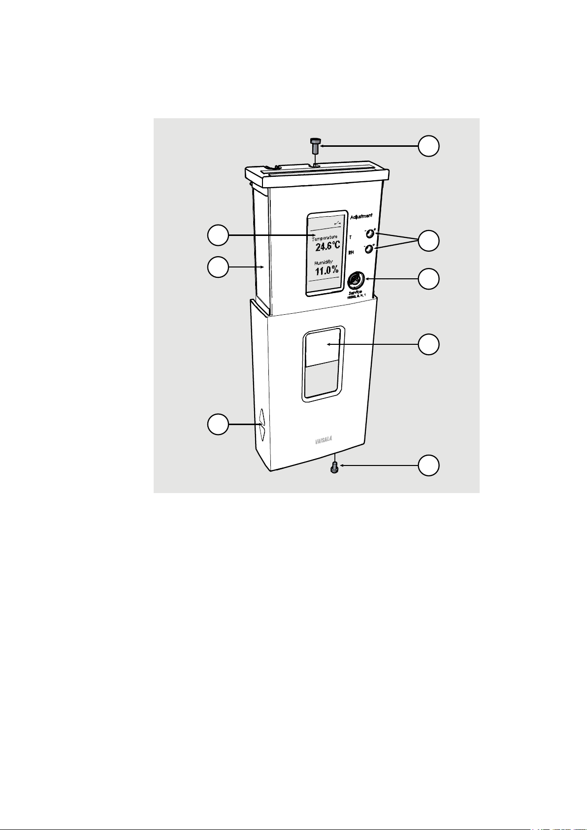
where
1 = Locking screw for mounting base.
Not included, M3×6 recommended.
2 = Adjustment trimmers
3 = Service port
4 = Window for display (only in models where the display is visible)
5 = Locking screw for slide. Not included, M3×6 recommended.
6 = Display
7 = Type label
8 = Grip for slide
6
7
8
1
2
3
4
5
Transmitter parts
1201-004
Figure 2 Transmitter Parts - Outside
16 ___________________________________________________________________ M211399EN-F
Page 19
Chapter 2 ___________________________________________________________ Product Overview
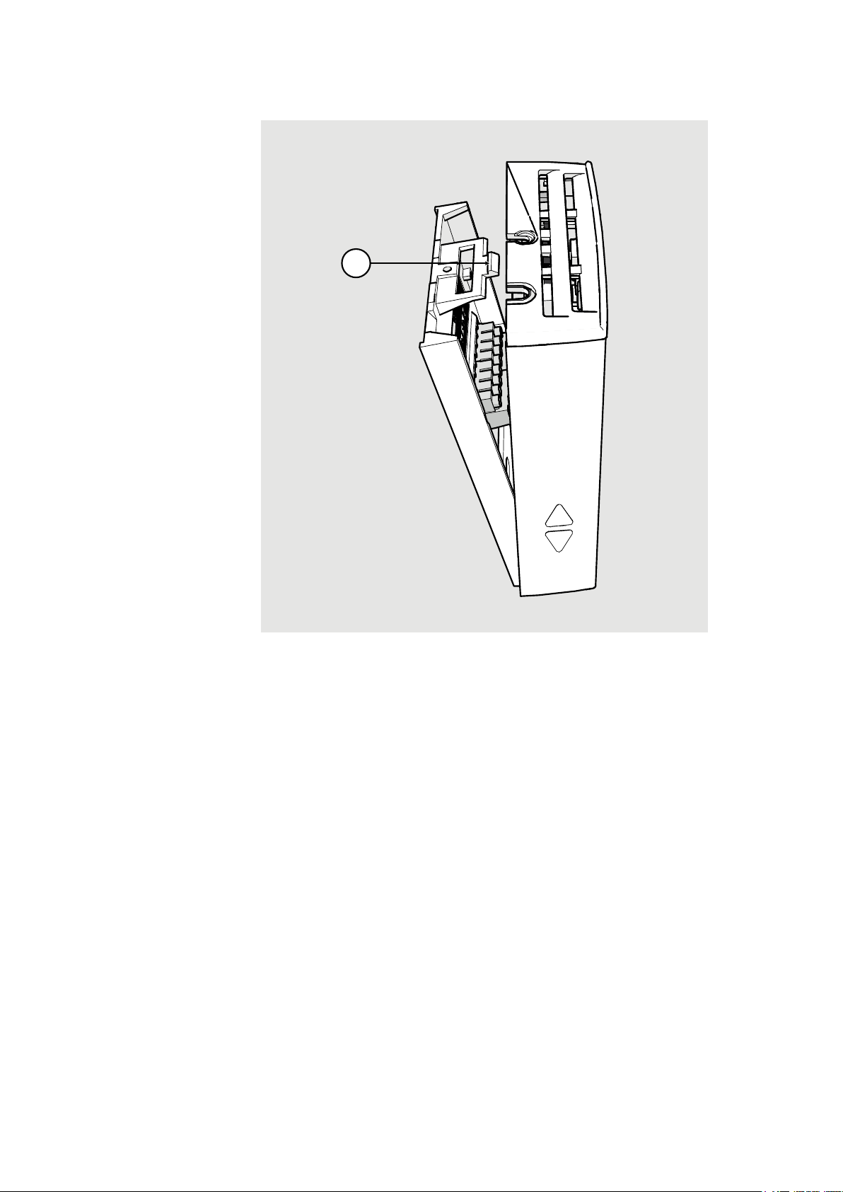
where
1 = Push tab down with a screwdriver to open the transmitter.
1
1201-005
Figure 3 Opening the Transmitter
VAISALA ________________________________________________________________________ 17
Page 20
User's Guide _______________________________________________________________________
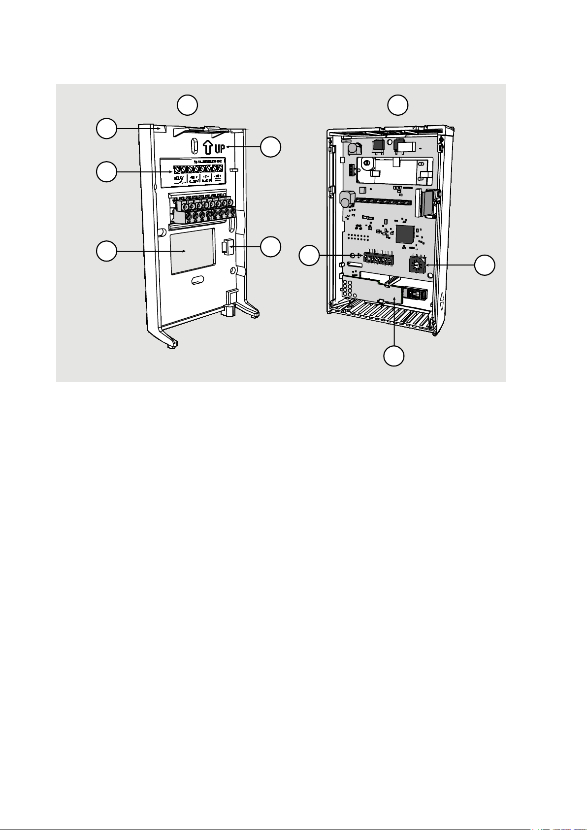
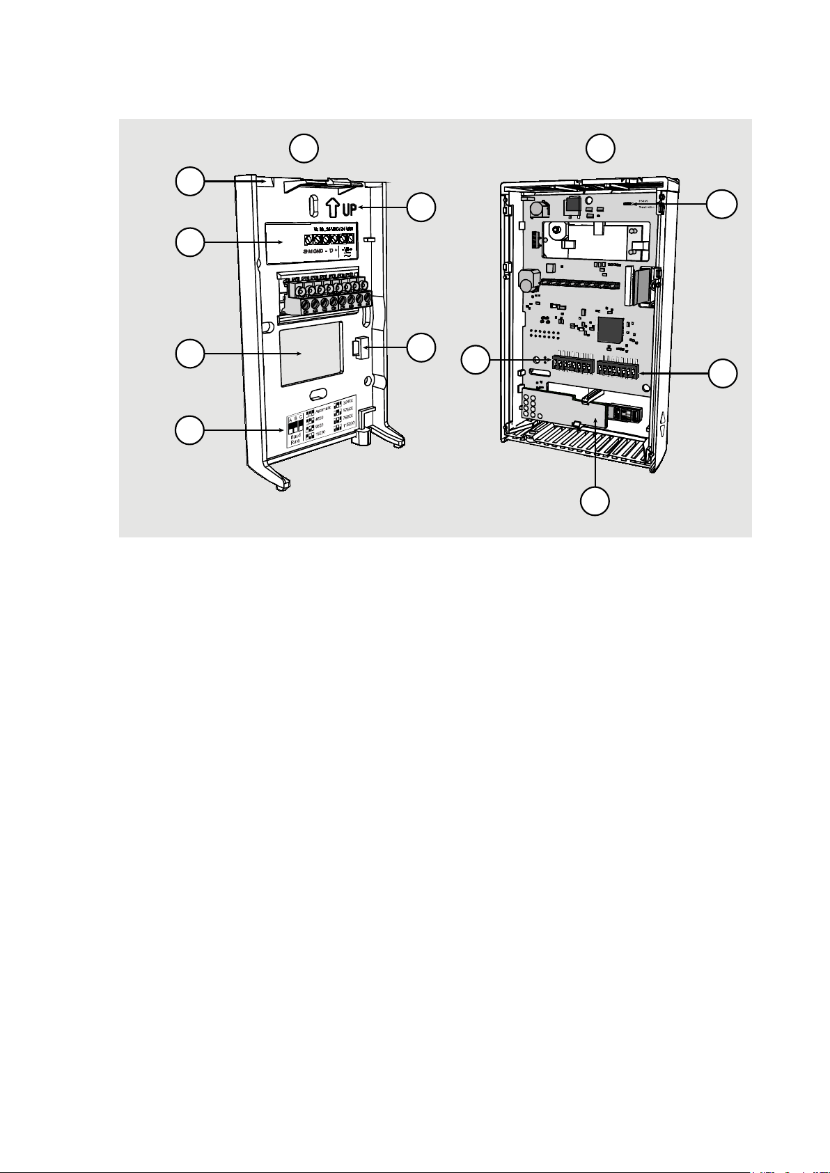
where
1 = Mounting base
2 = Opening for cable (wiring from top)
3 = Terminal label
4 = Opening for cable (wiring from behind)
5 = Orientation arrow – should point up after the mounting base has
been installed.
6 = Place for zip tie (for cable strain relief)
7 = Transmitter body
8 = DIP switches for common configuration options; see section DIP
Switches of Analog Output Models on page 22.
9 = HTM10 module with HUMICAP® sensor (HMW models) or
TM10 module (TMW models, measures temperature only).
10 = Rotary switch for relay setpoint (only for models with relay);
see section Relay Configuration in DIP Mode on page 23.
N
on-M e tri c
Td
0...5 V
Rela y O n
Rela y H ig h
Cus to m
R
e
l
a
y
S
e
t
P
o
i
n
t
M
etric
RH
0...1 0V
Rela y O ff
Rela y L ow
DIP
8
2
3
4
10
5
6
9
1
7
1201-006
Figure 4 Transmitter Parts – Inside (Analog Output Models)
18 ___________________________________________________________________ M211399EN-F
Page 21
Chapter 2 ___________________________________________________________ Product Overview
where
1 = Mounting base
2 = Opening for cable (wiring from top)
3 = Terminal label
4 = Opening for cable (wiring from behind)
5 = Label for RS-485 baud rate DIP switch settings
6 = Orientation arrow – should point up after the mounting base has
been installed.
7 = Place for zip tie (for cable strain relief)
8 = Transmitter body
9 = DIP switches for common configuration options; see section DIP
Switches of Analog Output Models on page 22.
10
=
RS-485 termination jumper (connects a 120 Ω resistor).
11 = Rotary switch for relay setpoint (only for models with relay);
see section Relay Configuration in DIP Mode on page 23.
12 = HTM10 module with HUMICAP® sensor.
9
2
3
4
6
7
12
1
8
11
10
5
1209-013
Figure 5 Transmitter Parts – Inside (Digital Output Models)
VAISALA ________________________________________________________________________ 19
Page 22

User's Guide _______________________________________________________________________
This page intentionally left blank.
20 ___________________________________________________________________ M211399EN-F
Page 23

Chapter 3 ________________________________________________________________ Installation
CHAPTER 3
INSTALLATION
This chapter provides you with information that is intended to help you
install the HMW90 series transmitters.
Configuration Before Installation
If you need to change the settings of the transmitter, it is best to do this
before it has been installed. Available configuration options are different
for analog output models (such as HMW93) and digital output models
(for example, HMW95).
Configuration of Analog Output Models
You can configure analog output models of HMW90 series transmitters
in two ways:
- Using the DIP switches (and rotary switch on the HMW93 and
TMW93) on the component board. See the following sections for
instuctions:
- DIP Switches of Analog Output Models on page 22
- Relay Configuration in DIP Mode on page 23
- Configuring the settings in software through the service port. See
connection instructions and serial line commands in Chapter 4,
Operation, on page 35.
These two configuration methods are mutually exclusive. If the DIP
switch configuration is used, software settings have no effect on settings
that are controlled by the DIP switches. DIP switch number 8 is the
master switch that controls which configuration method is used.
VAISALA ________________________________________________________________________ 21
Page 24
User's Guide _______________________________________________________________________
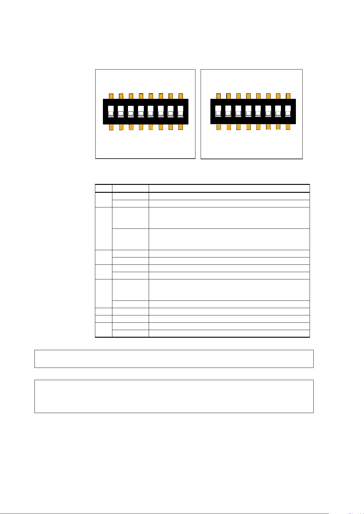
DIP
Position
Setting
1
Non-metric
Non-metric units (°F).
Metric
Metric units (°C).
2
Td
Td (dewpoint) as humidity parameter on display and
to -20 ... +55 °C.
RH
RH (relative humidity) as humidity parameter on display
0 ... 100 %RH.
3
0...5V
0...5V analog output (both channels).
0...10V
0...10V analog output (both channels).
4
Relay On
Relay enabled.
Relay Off
Relay disabled.
5
Relay High
Relay closed when measurement above setpoint.
TMW93.
Relay Low
Relay closed when measurement below setpoint.
6
Not used
7 Not used
8 Custom
Configuration through service port only.
DIP
Configuration by DIP switches only.
Non-Metric
Td
0...5V
Relay On
Relay High
Custom
Metric
RH
0...10V
Relay Off
Relay Low
DIP
1
2 3 4
5 6
7
8
Non-Metric
Td
Custom
Metric
RH
DIP
1
2 3 4
5 6
7
8
HMW92/TMW92 HMW93/TMW
93
DIP Switches of Analog Output Models
Figure 6 DIP Switch Settings of Analog Output Models
analog output. Sets analog output scaling
and analog output. Sets analog output scaling to
Relay operation is linked to RH on HMW93, and T on
1111-066
NOTE
DIP switch 2 does nothing on TMW92 and TMW93.
NOTE
If DIP switch 8 is set to Custom, the transmitter ignores all other DIP
switch settings. In custom mode the transmitter uses settings that are
configured in software using the service port.
22 ___________________________________________________________________ M211399EN-F
Page 25

Chapter 3 ________________________________________________________________ Installation
Relay is included on HMW93
Rotary Switch Position
Setpoint on HMW93
Setpoint on TMW93
0
5 %RH
0 °C (32 °F)
1
10 %RH
5 °C (41 °F)
2
20 %RH
10 °C (50 °F)
3
30 %RH
15 °C (59 °F)
4
40 %RH
20 °C (68 °F)
5
50 %RH
25 °C (77 °F)
6
60 %RH
30 °C (86 °F)
7
70 %RH
35 °C (95 °F)
8
80 %RH
40 °C (104 °F)
9
90 %RH
45 °C (113 °F)
The rotary switch only has 10 positions. Do not turn the switch so that it
is between two positions.
If you change the position of DIP switch 8, note the following:
- When changing from Custom to DIP: Current custom settings are
overwritten by the settings from the DIP switches at next power up.
Settings that do not have DIP switches remain unchanged, except for
display layout (DSEL command) that is set to default.
- When changing from DIP to Custom: The DIP settings that were
used when the power was last on are carried over to the custom
settings at next power up.
Relay Configuration in DIP Mode
NOTE
and TMW93 transmitters only.
When the transmitter is configured using DIP switches, the functioning
of the relay is configured by DIP switch 5 and the rotary switch on the
component board:
- DIP switch 5 determines if the relay is closed above or below the
setpoint.
- The position of the rotary switch determines the setpoint according to
the table below.
Table 5 Rotary Switch and Relay Setpoint
NOTE
VAISALA ________________________________________________________________________ 23
Page 26
User's Guide _______________________________________________________________________
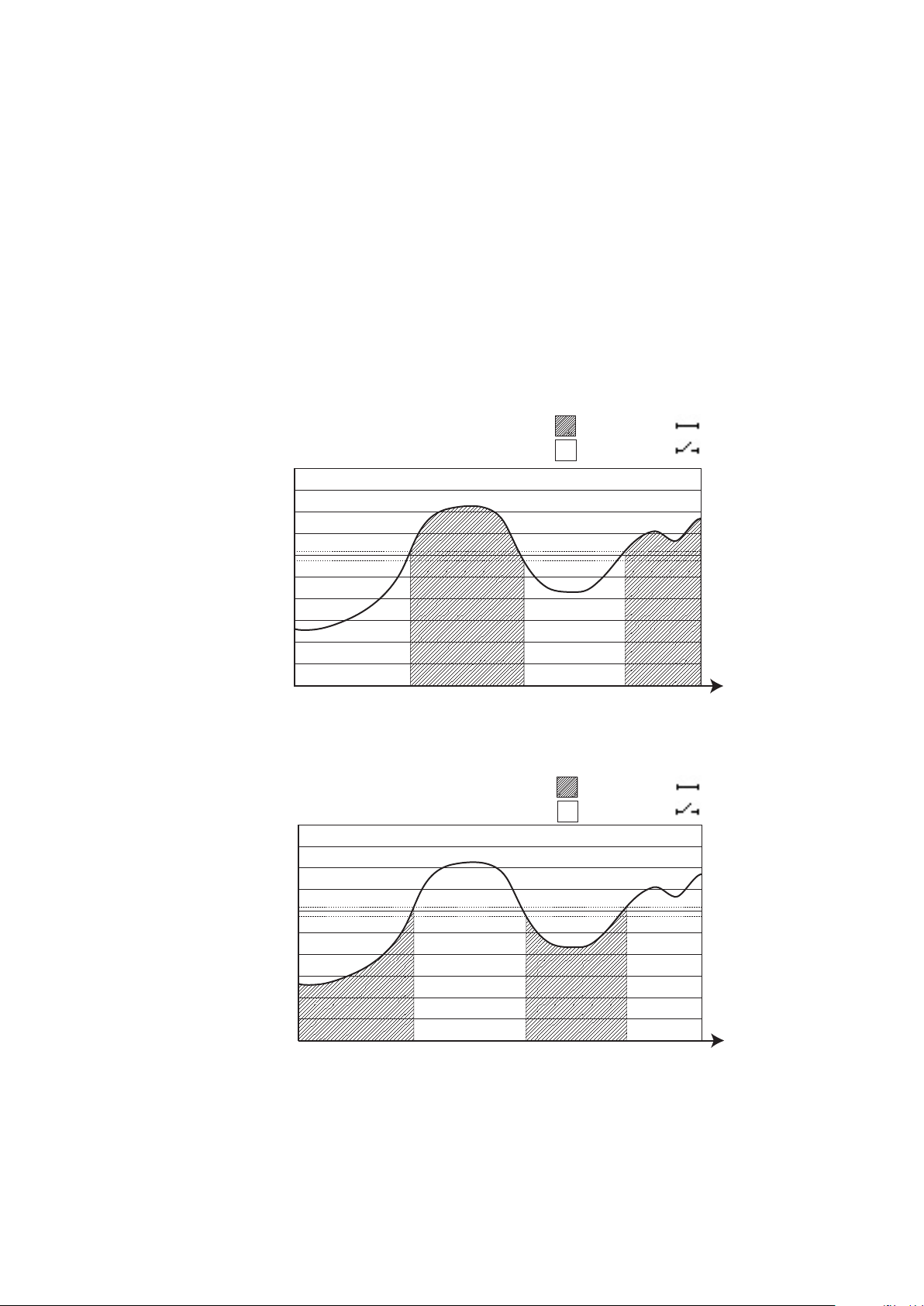
90
70
80
100
60
50
40
Relative Humidity (%)
Time
30
20
10
0
Rotary switch set to 6 (60 %RH)
DIP 5 set to “Relay High”
Relay closed
Relay open
90
70
8
0
100
6
0
50
40
Relative H
umid
ity
(%)
Time
30
20
10
0
Re
lay
c
lo
s
ed
Rel
a
y o
pe
n
R
ota
ry sw
itc
h se
t t
o 6
(
60
%RH)
DI
P 5 s
et t
o “Re
l
ay
Lo
w
”
For examples of relay behavior in DIP mode, see Figure 7 and Figure 8
on page 24. Note also the following:
- Relay operation in DIP mode is linked to RH measurement on
HMW93, and to T measurement on TMW93.
- Relay contacts are open if the transmitter is in error state (an active
error is present).
- Relay contacts are open when transmitter is powered off.
If you need to configure the relay for some other parameter or need
additional configuration options, see section Relay Configuration in
Custom Mode on page 55.
24 ___________________________________________________________________ M211399EN-F
1111-117
Figure 7 Relay High in DIP Mode (HMW93)
1111-118
Figure 8 Relay Low in DIP Mode (HMW93)
Page 27

Chapter 3 ________________________________________________________________ Installation
There is a hysteresis around the setpoint
switching when the measured value moves around the setpoint. This
means that the relay will not close or open exactly at the setpoin
slightly above and below.
NOTE
value to prevent rapid relay
t, but
- On HMW93 the hysteresis is 2 %RH in both directions.
- On TMW93 the hysteresis is 1 °C (1.8 °F) in both directions.
Configuration of Digital Output Models
Digital output models of the HMW90 series have the following
configuration interfaces:
- DIP switches on the component board control operating protocol,
serial line settings, and transmitter MAC address. For instructions, see
DIP Switches of Digital Output Models on page 26.
- You can set a jumper for RS-485 line termination on the component
board (120 Ω resistor). For location of the jumper, see Figure 5 on
page 19.
- Other settings are configured in software. You can change most
configuration settings through the service port. For connection
instructions and serial line commands, see Chapter 4, Operation, on
page 35.
- Some configuration actions can be done using the BACnet and
Modbus protocols. See the following appendices for protocol
implementation details:
- Appendix A, BACnet Reference, on page 87.
- Appendix B, Modbus Reference, on page 103.
VAISALA ________________________________________________________________________ 25
Page 28
User's Guide _______________________________________________________________________
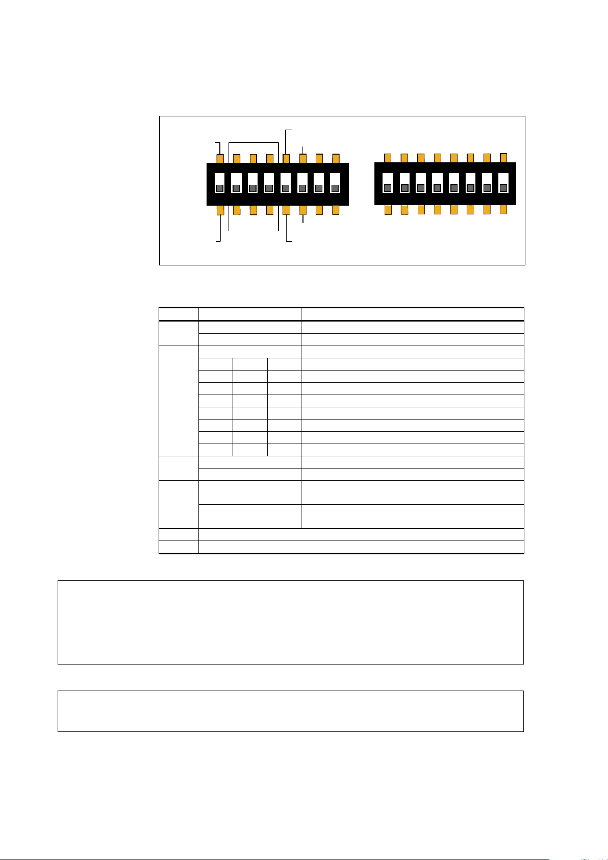
DIP
Position
Setting
1
Modbus
Modbus protocol in use.
BACnet
BACnet protocol in use.
2 ... 4
A B C
Serial line baud rate.
Off
Off
Off
Automatic (default).
Off
Off
On
4800 (not available with BACnet protocol)
Off
On
Off
9600
Off
On
On
19200
On
Off
Off
38400
On
Off
On
57600
On
On
Off
76800
On
On
On
115200
5
Parity Even
Parity even.
Parity None
Parity none.
6
Non-Metric
Use non-metric units on display and service
port. No effect on Modbus and BACnet.
Metric
Use metric units on display and service port.
No effect on Modbus and BACnet.
7
Not used
8
Not used
1
ON
2 3 4
5 6
7
8
Modbus
BACnet
Parity Even
A B C
Parity None
Baud
Rate
1
2 3 4
5 6
7
8
HMW95
128 64 32 16 8 4 2 1
Address
(Binary Weighting)
ON
Metric
Non-Metric
DIP Switches of Digital Output Models
Figure 9 DIP Switch Settings of Digital Output Models
1209-016
NOTE
If the serial line baud rate is set to Automatic, the transmitter attempts to
determine the baud rate of the traffic in the RS-485 network. The
transmitter cycles through all baud rate choices, listening for 10 seconds
at each rate. When it detects valid RS-485 traffic, it remains at the
detected baud rate until it is reset or power cycled.
NOTE
26 ___________________________________________________________________ M211399EN-F
The parity setting is only relevant for Modbus protocol, in which it
chooses between 8N2 (parity none) and 8E1 (parity even) formats.
Page 29

Chapter 3 ________________________________________________________________ Installation
1
2 3
4
5 6
7
8
128 64 32 16 8 4 2 1
ON
Binary: 10100001
Decimal: 161
(128 + 32 + 1)
=
Dip switches marked Address (Binary Weighting) set the MAC address
of the HMW90 series digital transmitter. The address is encoded in eight
bit binary form, with each numbered switch representing a single bit. For
example:
1209-009
Figure 10 Example of Transmitter Addressing
Addressing with BACnet Protocol
BACnet MS/TP MAC address range is 0 … 255. The transmitter is a
BACnet MS/TP master if address is below 128. Otherwise the transmitter
is a slave.
Addressing with Modbus Protocol
Transmitter is always a Modbus slave. MAC Address range for Modbus
slaves is 1 … 247.
VAISALA ________________________________________________________________________ 27
Page 30
User's Guide _______________________________________________________________________
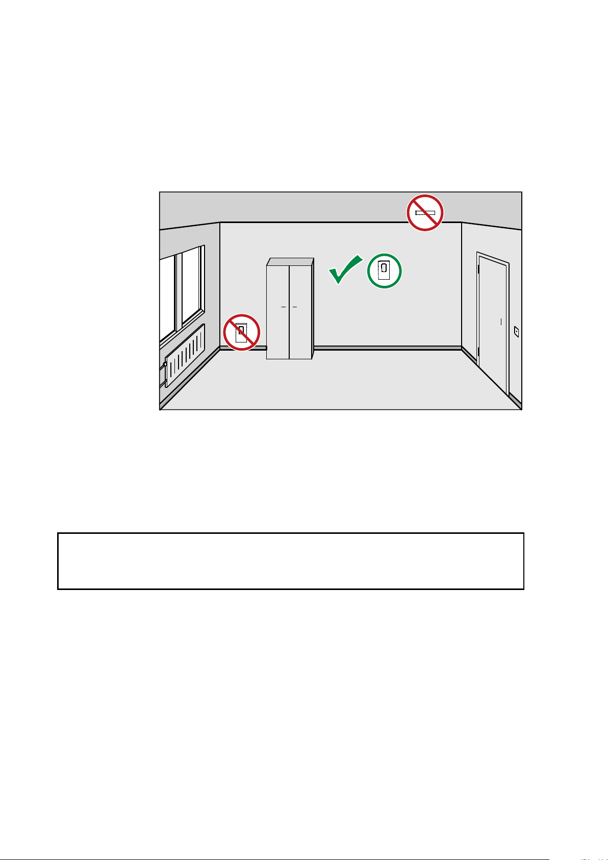
Selecting Location
The conditions at the location should represent well the area of interest.
Do not install the transmitter on the ceiling. Avoid placing the transmitter
near heat and moisture sources, close to the discharge of the supply air
ducts, and in direct sunlight.
CAUTION
1111-070
Figure 11 Selecting Transmitter Location
Use the mounting holes to attach the mounting base securely. Use at least
two screws (not included, max screw diameter 4 mm). Remember to
leave sufficient clearance below the transmitter to operate the slide. For
mounting dimensions, see section Dimensions in mm on page 86.
The arrow on the mounting base must point straight up after installation.
Proper orientation is important: air must flow through the vents on the
bottom and top.
28 ___________________________________________________________________ M211399EN-F
Page 31

Chapter 3 ________________________________________________________________ Installation
Connect only de
When wiring the transmitter, make sure the electrical conduit or cable is
not supplying air from outside the room into the transmitter. Seal the
cable opening if necessary.
-T -RH+T +RH
Power supply
10 ... 28 VDC
R
L
= 0 ... 600 Ω
Power supply
10 ... 28 VDC
R
L
= 0 ... 600 Ω
mA
mA
-
T -RH
+T +R
H
mA
mA
Po
wer s
upply
10
... 28
VDC
RL= 0 .
.. 600 Ω
Wiring
Connect the wiring to the screw terminals on the mounting base. The
supply voltage and terminal assignments are model-specific. Max wire
size 2 mm2 (AWG14).
After completing the wiring, connect the transmitter body over the
mounting base. Note that mounting bases are model-specific.
WARNING
NOTE
-energized wires.
Wiring HMW92
You must connect the RH channel of the HMW92, even if you only want
to measure temperature. Connecting the T channel is optional.
Figure 12 Wiring HMW92
If you want to use a single power supply for the HMW92, you must
connect the positive terminals (+T and +RH) together.
VAISALA ________________________________________________________________________ 29
Figure 13 Three-Wire Wiring for HMW92
1111-067
1211-007
Page 32

User's Guide _______________________________________________________________________
-T -Vs+T +Vs
Power supply
18 ... 35 VDC
or 24 VAC ±20%
-RH +RH
V
V
Relay
max. 50 VDC
500 mA
R
L
= 10 kΩ min.
-T -Vs+T +Vs
Power supply
18 ... 35 VDC
or 24 VAC ±20%
-RH +RH
V
V
Relay
R
L
= 10 kΩ min.
Wiring HMW93
Recommended wiring for long cables:
1111-068
Figure 14 Wiring HMW93
3-wire connection with -Vs as common ground. Maximum cable
resistance is 2.5 Ω (24V supply, 0 ... 10 V output, relay not used).
1111-069
Figure 15 Three-Wire Wiring for HMW93
30 ___________________________________________________________________ M211399EN-F
Page 33

Chapter 3 ________________________________________________________________ Installation
-T +T
Power supply
10 ... 28 VDC
R
L
= 0 ... 600 Ω
mA
-T -Vs+T +Vs
Power supply
18 ... 35 VDC
o
r 24
VAC
±20%
V
Relay
max. 50 VDC
500 mA
RL= 10 kΩ min.
-
T -Vs
+T +
Vs
Power
sup
ply
1
8 ..
. 35
VDC
or 24 V
AC ±
20%
V
R
elay
RL= 10 kΩ m
in.
Wiring TMW92
1202-117
Figure 16 Wiring TMW92
Wiring TMW93
Recommended wiring for long cables:
1202-118
Figure 17 Wiring TMW93
3-wire connection with -Vs as common ground. Maximum cable
resistance is 2.5 Ω (24V supply, 0 ... 10 V output, relay not used).
1202-119
Figure 18 Three-Wire Wiring for TMW93
VAISALA ________________________________________________________________________ 31
Page 34

User's Guide _______________________________________________________________________
+Vs OUT
-Vs
+Vs OUT
-Vs GND
Shared
common
line
HMW93
HMW93
CONTROLLER
24 VAC
Supply
volt
age
Supply
voltage
Signal
output
Signal
output
GND
Connecting a Common AC Power Supply to Several Transmitters
If you are connecting a common 24 VAC power supply to several
transmitters, make sure to connect the same terminal to +Vs and –Vs on
all transmitters. This will avoid a short-circuit through the shared
common line at the controller; see Figure 19 below.
1112-026
Figure 19 Connecting a Common AC Power Supply (HMW93)
32 ___________________________________________________________________ M211399EN-F
Page 35

Chapter 3 ________________________________________________________________ Installation
D- -VsD+ +Vs
+
-
P
o
we
r
su
pp
l
y
1
8 .
.
. 3
5 V
D
C
o
r 2
4
VA
C ±
20%
RS
-485
Sh
ld
G
ND
Transmit
te
r
D-
-Vs
D+
+Vs
Shld
GND
B
uil
ding
con
tro
ller
Tra
nsm
itt
er Transmit
t
er
Power
s
upp
ly
D-
D
+
+Vs
-
Vs
GND
SHIELD
RS-485:
B
ACnet or
MO
DBUS
mas
ter
C
onnect shield o
n contr
oller s
ide
Set RS-
485
t
ermination jump
er
D-
-V
s
D+
+Vs
Shld
GND
D-
-Vs
D+
+Vs
Shld
G
ND
Wiring HMW95
The RS-485 line of the transmitter is isolated from the power supply. A
separate ground reference terminal (GND) is provided for the RS-485
connection.
If you are using a shielded cable, you can use the Shld terminal to hold
the exposed part of the shield. Note that the Shld terminal is floating
(not electrically connected).
1209-014
Figure 20 Wiring HMW95
Connecting Several Transmitters on Same RS-485
Line (HMW95)
Set the RS-485 termination jumper to “ON” on the transmitter that is at
the end of the line. This terminates the line with a 120 Ω resistor. For
location of the jumper, see section Transmitter Parts - Inside on page 6.
Connect the cable shield to ground on the building controller side.
VAISALA ________________________________________________________________________ 33
Figure 21 Several Transmitters on Same RS-485 Line
1209-015
Page 36

User's Guide _______________________________________________________________________
This page intentionally left blank.
34 ___________________________________________________________________ M211399EN-F
Page 37

Chapter 4 _________________________________________________________________ Operation
CHAPTER 4
OPERATION
This chapter contains information that is needed to operate the HMW90
series transmitters.
Display
Startup Screens
When the transmitter is powered on, it displays a sequence of
information screens. The screens are shown for a few seconds each.
1111-073, 1111-074
Figure 22 HMW93 Startup Screens
VAISALA ________________________________________________________________________ 35
Page 38

User's Guide _______________________________________________________________________
Measurement Screen
Measurement screen shows the measured parameters and currently active
indicators.
1111-071
Figure 23 HMW93 Measurement Screen – Normal Operation
If there is a problem with measurement, affected readings are replaced
with stars. The alarm indicator and an error message will also appear on
the screen.
1111-072
Figure 24 HMW93 Measurement Screen – Problem With
Measurement
36 ___________________________________________________________________ M211399EN-F
Page 39

Chapter 4 _________________________________________________________________ Operation
Indicator
Position on Screen
Meaning
Top right
Is shown when relay contacts are open
Top right
Is shown when relay contacts are closed
Top left
Is shown when an MI70 Indicator is
Bottom left
Is shown if an error is active. The error
page 76.
The s
transmitter electronics. Connect only equipment with a floating power
supply (not ground
grounded to a different potential
will affect the
even affect the transmitter’s functionality or cause d
transmitter.
Indicators on the Display
(HMW93 and TMW93 only).
(HMW 93 and TMW93 only).
connected to the service port.
Service Port
You can connect to the service port on the HMW90 series transmitters
using a PC or an MI70 indicator. The MI70 indicator is the hand-held
display device that is included with, for example, the Vaisala
HUMICAP® Hand-Held Humidity and Temperature Meter HM70.
CAUTION
message is written after the indicator. See
section Error Messages on the Display on
ervice port is not galvanically isolated from the rest of the
ed) to the service port. If you connect a device that is
than the transmitter’s power supply, you
accuracy of the transmitter’s analog outputs. You may
amage to the
Connecting With an MI70 Indicator
When connecting using an MI70 indicator, use the connection cable for
HM70 hand-held meter (Vaisala order code 219980). The following
functionality is available when using the MI70:
- Standard MI70 functions such as viewing, logging, and graphs of
measurement results.
- Calibration and adjustment fuctions for the transmitter. For more
information, see section Adjustment Using an HM70 on page 70.
- Setting of the pressure compensation value for humidity measurement
(Environment menu in the MI70).
VAISALA ________________________________________________________________________ 37
Page 40

User's Guide _______________________________________________________________________
Connecting With a PC
Connecting with a PC allows you to configure and troubleshoot your
transmitter using serial line commands. For a list of commands, see
section List of Serial Commands on page 41.
When connecting using a PC, use the Vaisala USB cable (Vaisala order
code 219690) and a suitable terminal application:
- If you have not used the Vaisala USB cable before, install the driver
before attempting to use the cable. Refer to section Installing the
Driver for the USB Service Cable on page 38 for detailed instructions.
- For more information on using a terminal application, see section
Terminal Application Settings on page 39.
Installing the Driver for the USB Service Cable
Before taking the USB service cable into use, you must install the
provided USB driver on your PC. When installing the driver, you must
acknowledge any security prompts that may appear.
1. Check that the USB service cable is not connected. Disconnect the
cable if you have already connected it.
2. Insert the media that came with the cable, or download the latest
driver from www.vaisala.com.
3. Execute the USB driver installation program (setup.exe), and
accept the installation defaults. The installation of the driver may
take several minutes.
4. After the driver has been installed, connect the USB service cable
to a USB port on your PC. Windows will detect the new device,
and use the driver automatically.
5. The installation has reserved a COM port for the cable. Verify the
port number, and the status of the cable, using the Vaisala USB
Instrument Finder program that has been installed in the
Windows Start menu.
Windows will recognize each individual cable as a different device, and
reserve a new COM port. Remember to use the correct port in the
settings of your terminal program.
There is no reason to uninstall the driver for normal use. However, if you
wish to remove the driver files and all Vaisala USB cable devices, you
can do so by uninstalling the entry for Vaisala USB Instrument Driver
from the Programs and Features menu in the Windows Control Panel.
In Windows XP and earlier Windows versions the menu is called Add or
Remove Programs.
38 ___________________________________________________________________ M211399EN-F
Page 41

Chapter 4 _________________________________________________________________ Operation
Property
Description / Value
Baud rate
19200
Parity
None
Data bits
8
Stop bits
1
Flow control
None
If PuTTY is unable to open the serial port you select
an error message instead. If this happens, restart PuTTY and check the
settings.
Terminal Application Settings
The serial interface settings of the service port are presented in Table 6
below. The settings are fixed, and cannot be changed by the user.
Table 6 Serial Interface Settings
The steps below describe how to connect to the transmitter using the
PuTTY terminal application for Windows (available for download at
www.vaisala.com) and a USB serial interface cable:
1. Connect the USB serial interface cable between your PC and the
service port of the transmitter.
2. Start the PuTTY application.
NOTE
3. Select the Serial settings category, and check that the correct COM
port is selected in the Serial line to connect to field.
Note: You can check which port the USB cable is using with the
Vaisala USB Instrument Finder program that has been installed
in the Windows Start menu.
4. Check that the other serial settings are correct for your connection,
and change if necessary. Flow control should be set to None unless
you have a reason to change it.
5. Click the Open button to open the connection window and start
using the serial line.
ed, it will show you
6. You may need to adjust the Local echo setting in the Terminal
category to see what you are typing on the serial line. To access the
configuration screen while a session is running, click the right
mouse button over the session window, and select Change
Settings... from the pop-up menu.
VAISALA ________________________________________________________________________ 39
Page 42

User's Guide _______________________________________________________________________
0807-004
Figure 25 PuTTY Terminal Application
40 ___________________________________________________________________ M211399EN-F
Page 43

Chapter 4 _________________________________________________________________ Operation
Command
Description
?
Show transmitter information.
CALCS
Show all measured and calculated parameters.
ECHO
Show or set remote echo mode.
ENV
Show or set environmental parameters.
ERRT
Show error table.
ERRS
Show currently active errors.
FORM [modifier string]
Show or set output format.
HELP
Show list of currently available serial commands.
INTV [0 ... 9999 s/min/h]
Set continuous output interval for R command.
PASS [9000]
Access advanced serial commands.
R
Start the continuous outputting.
RESET
Reset the transmitter.
S
Stop the continuous outputting.
SDELAY [0 ... 255]
Show or set serial line transmission delay in
milliseconds.
SEND
Output measurement message once.
SNUM
Show transmitter serial number.
STATUS
Show transmitter status.
UNIT [m/n]
Select metric or non-metric units.
VERS
Show transmitter firmware version.
Command
Description
AMODE
Show or set analog output mode.
AOVER
Show or set analog output overrange and clipping
behavior.
ASEL
Show or set analog output parameter.
ATEST
Test analog putput.
BACNET
Show or set BACnet parameters.
CDATE
Show or set calibration date.
CRH
Calibrate and adjust RH measurement.
CT
Calibrate and adjust T measurement.
CTEXT
Show or set calibration information.
DSEL
Select parameters to display on screen.
FRESTORE
Restore transmitter to factory settings.
RMODE
Show or set relay operation mode.
RSEL
Show or set relay parameter and limits.
RTEST [open/closed]
Test relay operation.
List of Serial Commands
Some commands, such as RSEL, are not available if the required feature
is not present on the transmitter, or the command is not relevant.
All commands can be issued either in uppercase or lowercase. In the
command examples, the keyboard input by the user is in bold type.
The notation <cr> refers to pressing the carriage return (Enter) key on
your computer keyboard. Enter a <cr> to clear the command buffer
before starting to enter commands.
Table 7 Basic Serial Commands
Table 8 Advanced Serial Commands
VAISALA ________________________________________________________________________ 41
Page 44

User's Guide _______________________________________________________________________
Transmitter Information
Show Transmitter Information
The ? command outputs a listing of device information.
?<cr>
Example:
>?
Device : HMW93
SW version : 1.00.0.0000
SNUM : G5130008
HTM10 module information
Software version : 1.00.0
SNUM : G5130007
Show Transmitter Firmware Version
Use the VERS command to show the transmitter model and firmware
version.
VERS<cr>
Example:
>vers
HMW93 / 1.00.0
Show Transmitter Serial Number
Use the SNUM command to show the transmitter serial number.
SNUM<cr>
Example:
>snum
Serial number : G5130008
42 ___________________________________________________________________ M211399EN-F
Page 45

Chapter 4 _________________________________________________________________ Operation
where
Function
=
Optional switch to display a more detailed status for
BACnet or Modbus protocol
models with digital output).
are -bacnet and –modbus.
Show Transmitter Status
Use the STATUS command to view detailed information on transmitter
model and configuration.
STATUS [function]<cr>
(available on transmitter
Available switches
Example (display detailed BACnet status):
>status –bacnet
* BACnet module (BACNET) *
BACnet protocol : active
MAC : 0 (00h)
Device Instance : 6 (00000006h)
Name : NOT_SET
Location : Location
Description : Description
MAX_MASTER : 127 (7Fh)
Node type : Master
Baud setting : Auto
Current baudrate : 19200 8N1
Baudrate locked : No
Baud detection interval: 10 s
DCC : Communication enabled
Valid frames : 0
Invalid frames : 0
Unwanted frames : 0
Lost tokens : 0
Failed TX : 0
VAISALA ________________________________________________________________________ 43
Page 46

User's Guide _______________________________________________________________________
Example (display full status):
>status
Device Name : HMW92
Copyright : Copyright Vaisala Oyj 2012
SW Name : XM90
SW Model : XM9x
SW version : 1.0.3.3728
Serial number : H1840005
Address : 0
SUB FUNCTIONS
* Serial Port (COM1) *
Mode : STOP
* Error Manager (ERR) *
Status : NORMAL
Active errors : 0
* MCI communication (MCI) *
Status : NORMAL
* Analog output 1 (AOUT1) *
Quantity : x
Input range : 0.000 ... 700.000 gr/lb
Output range : 4.000 ... 20.000 mA
Output clipping : 0.00 % (4.00 ... 20.00 mA)
Valid output range : 5.00 % (3.20 ... 20.80 mA)
Error value : 3.600 mA
Input now : 17.301 gr/lb
Output now : 4.395 mA
State : Normal
* Analog output 2 (AOUT2) *
Quantity : a
Input range : 0.000 ... 10000.210 gr/ft3
Output range : 4.000 ... 20.000 mA
Output clipping : 0.00 % (4.00 ... 20.00 mA)
Valid output range : 5.00 % (3.20 ... 20.80 mA)
Error value : 3.600 mA
Input now : 1280.323 gr/ft3
Output now : 6.048 mA
State : Normal
* Measurement module (HTM10) *
Status : NORMAL
Factory date : 20120425
44 ___________________________________________________________________ M211399EN-F
Page 47

Chapter 4 _________________________________________________________________ Operation
Using this command on
parameters
parameters
Show Measured Parameters
Use the CALCS command to list the measurement parameters that are
supported by the HMW90 series transmitters. RH and T are measured
directly by the transmitter, the rest are calculated based on the measured
values.
CALCS<cr>
Example:
>calcs
RH - Relative Humidity
T - Temperature
Tdf - Dew/Frost point temperature
Td - Dew point temperature
Tw - Wetbulb temperature
h - Enthalpy
x - Mixing ratio
a - Absolute humidity
dTd - Dew/frostpoint depression
NOTE
TMW92 and TMW93 transmitters will list all
, even though these transmitters only provide the temperature
.
Show Command Help
To see a short description of an individual command, issue the command
with a question mark as a parameter.
Example:
>calcs ?
Display measured quantities
VAISALA ________________________________________________________________________ 45
Page 48

User's Guide _______________________________________________________________________
where
pressure
=
Ambient pressure in hPa.
Show Command List
Use the HELP command to list the currently available serial commands.
If the PASS command has not been used, only the basic serial commands
are available.
HELP<cr>
Example (shows basic serial commands, advanced commands are not
enabled here):
>help
?
CALCS
ECHO
ENV
ERRT
ERRS
FORM
HELP
INTV
PASS
R
RESET
SDELAY
SEND
SNUM
STATUS
UNIT
VERS
Measurement Settings
Set Environmental Parameters
Use the ENV command to set environmental parameters that affect the
measurement. For HMW90 series transmitters you can set the ambient
pressure value that is used for pressure compensation of calculated
parameters.
ENV [pressure]<cr>
Example:
>env 1013.3
Pressure (hPa) : 1013.3
46 ___________________________________________________________________ M211399EN-F
Page 49

Chapter 4 _________________________________________________________________ Operation
where
x = Selects the unit type to output:
m = metric units, for example, Celsius
n = non-metric units, for example, Fahrenheit
Commands for configuring analog outputs are not available on digital
output models (for example, HMW95).
where
channel
=
Analog output channel, 1 or 2.
lo_value
=
Low limit of the channel.
hi_value
=
High limit of the channel.
error_value
=
Error value of the channel.
Select Units
Use the UNIT command to select metric or non-metric output units.
Only affects data shown on the display and service port, has no effect on
the analog and digital outputs. This command is not available on the
digital output models (for example, HMW95).
UNIT [x]<cr>
Example:
>unit m
Unit : Metric
Analog Output Settings
NOTE
Set Analog Output Mode
Use the AMODE command to set the analog output mode and error
level. Note that you cannot change between analog output types, for
example, from voltage to current output.
AMODE [channel lo_value hi_value error_value]<cr>
Example (show current configuration):
>pass 9000
>amode
Aout 1 range ( V) : 0.00 ... 5.00 (error: 5.50)
Aout 2 range ( V) : 0.00 ... 5.00 (error: 5.50)
Example (set channel 1 to 0 ... 1 V output, with error level at 2 V):
>amode 1 0 1 2
Aout 1 range ( V) : 0.00 ... 1.00 (error: 2.00)
VAISALA ________________________________________________________________________ 47
Page 50

User's Guide _______________________________________________________________________
where
channel
=
Analog output channel, 1 or 2.
parameter
=
Parameter that is output on the channel.
dTd dew/frost point depression
lo_value
=
Low limit of the scaling, in the units of the selected
parameter.
hi_value
=
High limit of the scaling in the units of the selected
parameter.
Set Analog Output Scaling
Use the ASEL command to select the output parameter and scaling for
analog output channels.
ASEL [channel parameter lo_value hi_value]<cr>
Available parameters are:
RH relative humidity
T temperature
Tdf dew/frost point temperature
Td dew point temperature
Tw wetbulb temperature
h enthalpy
x mixing ratio
a absolute humidity
Example (set channel 1 to output dewpoint, in the range -10 ... 20 °C):
>pass 9000
>asel 1 TD -10 20
Aout 1 quantity : Td (-10.00 ... 20.00 'C)
48 ___________________________________________________________________ M211399EN-F
Page 51

Chapter 4 _________________________________________________________________ Operation
where
channel
=
Analog output channel, 1 or 2.
clip%
=
Output margin (%) at which the output is clipped.
Range 0 ... 20, default is 0.
valid%
=
Output margin (%) at which the output of the channel
goes into the error state. Range 0 ...
The error state is defined using the
see section Set Analog Output Mode on page 47.
These settings have no effect on the measurements shown on the display.
The display will always s
outside the scaled output range, as long as the measurement is still
functioning.
Set Output Clipping and Error Limit
Use the AOVER command to define the behavior of the analog outputs
when the measured value is outside the scaled output range.
AOVER [channel clip% valid%]<cr>
20, default is 5.
AMODE command,
NOTE
how the currently measured values, even
For example, first check the analog output settings using ASEL,
AMODE, and AOVER commands:
>pass 9000
>asel
Aout 1 quantity : RH (0.00 ... 100.00 %)
Aout 2 quantity : T (-5.00 ... 55.00 'C)
>amode
Aout 1 range ( V) : 1.00 ... 5.00 (error: 6.00)
Aout 2 range ( V) : 1.00 ... 5.00 (error: 6.00)
>aover
Aout 1 clipping : 0.00 %
Aout 1 error limit : 5.00 %
Aout 2 clipping : 0.00 %
Aout 2 error limit : 5.00 %
The parameter for channel 2 is T, with standard output range 1 ... 5 V and
scaling -5 ... 55 °C. Error state is 6 V, which is set when the measured
value is 5% outside the scaled output range.
Now give the following AOVER command:
>aover 2 10.0 20.0
Aout 2 clipping : 10.00 %
Aout 2 error limit : 20.00 %
VAISALA ________________________________________________________________________ 49
Page 52

User's Guide _______________________________________________________________________
where
Q1 = First parameter to show on the screen. Available parameters
are:
out1
out2
RH
T
Tdf
Td
Tw
h
x
a
dTd dew/frost point depression
Q2 = Second parameter to show on the screen. Available
parameters are the same as for Q1.
Q3 = Third parameter to show on the screen. Available parameters
are the same as for Q1.
Channel 2 now behaves like this:
- Clipping is now set to 10%, meaning the output is allowed to vary
between 0.6 ... 5.4 V. The channel will output the measurement for
-11 ... 61 °C, but range 1 ... 5 V remains scaled to show -5 ... 55 °C.
- Error limit is 20%, which means channel 2 will show the error state
(6 V) when the measured value is 20% outside the scaled output
range. With the settings above, this will happen if the measured
temperature is outside range -17 ... 67 °C.
- The output will never actually be between 5.4 and 6.0 V because of
clipping.
Display Settings
Select Parameters to Display
Use the DSEL command to select the parameters that are displayed on
the transmitter screen. You can select parameters by abbreviation, or
select same parameters as are assigned to the analog outputs. If only one
parameter is selected, it is shown vertically centered on the transmitter
screen.
DSEL [Q1 Q2 Q3]<cr>
Same parameter as analog output channel 1
Same parameter as analog output channel 2
relative humidity
temperature
dew/frost point temperature
dew point temperature
wetbulb temperature
enthalpy
mixing ratio
absolute humidity
50 ___________________________________________________________________ M211399EN-F
Page 53

Chapter 4 _________________________________________________________________ Operation
Example (show currently displayed parameters):
>pass 9000
>dsel
Quant 1 : T
Quant 2 : RH
Quant 3 : Disabled
Example (change display to only show RH):
>dsel RH
OK
Example (change display to show same parameters as are assigned to
analog output channels):
>dsel out1 out2
OK
Serial Line Output Commands
Start Measurement Output
Use the R command to start the continuous outputting of measurement
values as an ASCII text string to the serial line. The format of the
measurement message is set with the FORM command.
R<cr>
Example (measurement message in default format):
>r
RH = 21.71 %RH T = 23.13 'C
RH = 21.72 %RH T = 23.12 'C
RH = 21.77 %RH T = 23.12 'C
RH = 21.77 %RH T = 23.12 'C
...
Outputting the results continues in intervals issued with the command
INTV. You can stop the output with the S command. Since the interface
is half-duplex, you must enter the commands when the transmitter is not
outputting.
Stop Measurement Output
You can stop the measurement output with the S command:
S<cr>
VAISALA ________________________________________________________________________ 51
Page 54

User's Guide _______________________________________________________________________
where
n = time interval, range 0 ... 9999.
xxx
=
time unit = "S", "MIN", or "H"
Output a Reading Once
Use the SEND command to output a single measurement message.
SEND<cr>
Example:
>send
RH = 21.72 %RH T = 23.12 'C
Set Output Interval
Use the INTV command to change the output interval of the
automatically repeating measurement messages. The measurement
messages are repeated in the RUN mode, or after the R command has
been given.
INTV [n xxx]<cr>
The shortest output interval (with n = 0) outputs the measurement
messages as quickly as the transmitter produces them, without additional
delay.
Example:
>intv 1 min
Output interval : 1 min
52 ___________________________________________________________________ M211399EN-F
Page 55

Chapter 4 _________________________________________________________________ Operation
where
modifier string
=
String of parameters and modifiers that defines the
output format, length 1 ... 15
Maximum length may be shorter when text strings
are used. See
and examples below.
Set Output Format
Use the serial line command FORM to change the measurement message
sent by the transmitter on the service port. You can freely define the
output message to include the desired parameters, formatting options,
text strings, and additional fields.
FORM [modifier string]<cr>
0 characters.
Table 9 and Table 10 on page 54,
Command to set default format:
>form /
Example of default output:
RH = 5.17 %RH T = 24.33 'C
RH = 5.17 %RH T = 24.33 'C
RH = 5.18 %RH T = 24.33 'C
RH = 5.18 %RH T = 24.33 'C
...
Command to set output format as Tdf and T with Modulus-256
checksum:
>form "Tdf =" U3 4.2 tdf " T =" U3 3.2 t CS2 \r \n
Output example:
Tdf = -15.72 'C T = 24.38 'C C9
Tdf = -15.71 'C T = 24.38 'C C8
Tdf = -15.71 'C T = 24.38 'C C8
Tdf = -15.69 'C T = 24.38 'C CF
...
Command to set output format as Tdf and T, with start of text (ASCII
character 002) and end of text (003) ASCII codes, and without line feed
and carriage return at the end:
>form #002 "Tdf =" U3 3.2 tdf " T =" U3 3.2 t #003
Output example (ASCII codes not visible here):
Tdf =-15.14 'C T = 24.40 'CTdf =-15.14 'C T = 24.40 'CTdf
=-15.14 'C T = 24.40 'CTdf =-15.14 'C T = 24.40 'CTdf =-
15.13 'C T = 24.40 'CTdf =-15.13 'C T = 24.40 'C ...
VAISALA ________________________________________________________________________ 53
Page 56

User's Guide _______________________________________________________________________
Measured Parameter
Abbreviation in FORM Command
Relative humidity
RH
Temperature
T
Dew/frost point temperature
Tdf
Dewpoint temperature
Td
Wetbulb temperature
Tw
Enthalpy
h
Mixing ratio
x
Absolute humidity
a
Dew/frost point depression
dTd
Modifier
Description
x.y
Length modifier (number of digits and decimal places)
#t
Tabulator
#r
Carriage-return
#n
Line feed
""
String constant, length 1 ... 15 characters
#xxx
ASCII code value (decimal) of a special character;
for example, #027 for ESC
Ux
Shows the name of the measurement unit using “x” number
measurement unit with three characters
CS2
Modulus-256 checksum of message sent so far, ASCII
encoded hexadecimal notation
CS4
Modulus-65536 checksum of message sent so far, ASCII
encoded hexadecimal notation
CSX
NMEA xor-checksum of message sent so far, ASCII encoded
hexadecimal notation
Table 9 FORM Command Parameters
Table 10 FORM Command Modifiers
of characters. For example, U3 shows the name of the
NOTE
When entering modifiers, you can also use the backslash character “\”
instead of the hash “#”.
Serial Line Settings
Set Remote Echo
Use the ECHO command to enable or disable remote echo by the
transmitter.
ECHO [on/off]<cr>
Example:
>echo on
Echo : ON
54 ___________________________________________________________________ M211399EN-F
Page 57

Chapter 4 _________________________________________________________________ Operation
where
delay
=
Serial line delay in milliseconds, range 1 … 1000.
Relay is included on HMW93 transmitters only.
where
mode
=
Activation mode of the relay. Options are:
None
Lo_active
Hi_active
Fault
Not_fault (relay closed when transmitter not in error state)
Set Serial Line Response Time
With the SDELAY command you can set delay (response time) of the
serial line, or view the currently set delay value.
SDELAY [delay]<cr>
Example:
>sdelay 5
COM1 transmit delay : 5
Relay Configuration in Custom Mode
NOTE
Additional configuration options are available when relay functionality is
configured via software. The configuration is done using the RMODE
and RSEL commands. For examples, see section Relay Configuration
Examples on page 57.
Set Relay Mode
Use the RMODE command to show or set the relay activation mode.
RMODE [mode]<cr>
(relay is disabled, always open)
(relay closed when below setpoint)
(relay closed when above setpoint)
(relay closed when transmitter in error state)
Example (set relay to Lo_active mode):
>pass 9000
>rmode lo_active
Relay mode : Lo_Active
VAISALA ________________________________________________________________________ 55
Page 58

User's Guide _______________________________________________________________________
where
parameter
=
Parameter that controls the relay. Available parameters
are:
RH
T
Tdf
Td
Tw
h
x
a
dTd
Disabled no parameter, relay disabled
lo_value
=
Low limit of relay activation.
hi_value
=
High limit of relay activation.
Set Relay Parameter and Limits
Use the RSEL command to show or set the parameter that controls the
relay, and the limits that are applied.
RSEL [parameter lo_value hi_value]<cr>
relative humidity
temperature
dew/frost point temperature
dew point temperature
wetbulb temperature
enthalpy
mixing ratio
absolute humidity
dew/frost point depression
Example (show current settings):
>pass 9000
>rsel
Relay configuration : RH (88.00 ... 92.00 %)
Example (set temperature as relay parameter, low limit 25, high limit 30):
>rsel t 25 30
Relay configuration : T (25.00 ... 30.00 'C)
56 ___________________________________________________________________ M211399EN-F
Page 59

Chapter 4 _________________________________________________________________ Operation
90
70
80
100
60
50
40
Re
lative Humidi
ty (%)
Time
30
20
10
0
Relay closed
Relay open
RSE
L RH 60 70
RMODE Hi_Active
9
0
7
0
80
10
0
60
50
4
0
Re
lati
ve H
umidity (
%)
T
i
me
30
2
0
10
0
Re
lay
c
lo
se
d
Rel
ay
op
e
n
RSE
L RH
60 7
0
RMO
DE L
o_Ac
tiv
e
Relay Configuration Examples
1111-119
Figure 26 Relay Hi_Active in Custom Mode (HMW93)
1111-120
Figure 27 Relay Lo_active in Custom Mode (HMW93)
VAISALA ________________________________________________________________________ 57
Page 60

User's Guide _______________________________________________________________________
Calibration and Adjustment Commands
The following sections describe the calibration and adjustment
commands of the HMW90 series. For general information on performing
calibration and adjustment on the serial line, see section Adjustment
Using a PC on page 71.
The 1-point humidity adjustment of the HMW90 series adjusts both
offset and gain, depending on the adjustment condition. In a dry
condition (for example, 11 %RH), offset is adjusted more than gain.
NOTE
NOTE
The 1-point humidity adjustment requires that the target condition is at
least 50% of the currently measured value. This prevents the user from
making excessive corrections that are very unlikely to be needed.
However, if you feel that you may have done an incorrect adjustment,
you can easily remove the adjustment using the CRH RESET command.
Adjust Humidity Measurement
Use the CRH command to perform a humidity adjustment of the relative
humidity (RH) measurement. You can do a 1-point or a 2-point
adjustment, or clear the adjustment information from the HTM10
module. Note that the factory adjustment will remain intact when user
adjustment is cleared.
The CRH command does nothing on the TMW92 and TMW93
transmitters.
Show Current RH Adjustment
CRH<cr>
Example (showing default offset and gain):
>pass 9000
>crh
RH Gain : 1.000
RH Offset : 0.000
58 ___________________________________________________________________ M211399EN-F
Page 61

Chapter 4 _________________________________________________________________ Operation
where
x = The reference humidity condition (%RH) that the transmitter
should be showing.
where
LO = Adjustment point at the dry end (low RH).
HI = Adjustment point at the wet end (high RH). The difference
between the two points should be at least 30 %RH.
x = The reference humidity condition (%RH) that the transmitter
should be showing.
1-point Adjustment of RH Measurement
The 1-point adjustment adjusts both offset and gain depending on the
adjustment condition. The same type of adjustment is done when turning
the RH trimmer.
Place the transmitter in the reference condition and allow it to stabilize
before entering the adjustment.
CRH [ONE] [x]<cr>
Example:
>pass 9000
>crh one 11
OK
2-point Adjustment of RH Measurement
CRH [LO | HI] [x]<cr>
The 2-point correction is not applied immediately – you must use the
CRH SAVE command to store your adjustment to the HTM10 module.
If you have entered user adjustments using the CRH command but do not
wish to commit them, use the CRH CANCEL command.
CRH [SAVE | CANCEL]<cr>
Example (two point adjustment, low point 11 %RH and high point 75
%RH):
>pass 9000
>crh lo 11
OK
>crh hi 75
OK
>crh save
OK
VAISALA ________________________________________________________________________ 59
Page 62

User's Guide _______________________________________________________________________
where
x = The reference temperature (in degrees Celsius) that the
transmitter should be showing.
Clear User Adjustment of RH Measurement
CRH [RESET]<cr>
Example:
>pass 9000
>crh reset
OK
Adjust Temperature Measurement
Use the CT command to perform an adjustment of the temperature
measurement. You can do a 1-point adjustment or clear the adjustment
information from the HTM10 module. Note that the factory adjustment
will remain intact when user adjustment is cleared.
Show Current T Adjustment
CT<cr>
Example (showing default temperature offset):
>pass 9000
>ct
Temperature offset : 0.000
1-point Adjustment of T Measurement
Place the transmitter in the reference condition and allow it to stabilize
before entering the adjustment.
CT [x]<cr>
Example:
>pass 9000
>ct 23
OK
60 ___________________________________________________________________ M211399EN-F
Page 63

Chapter 4 _________________________________________________________________ Operation
Clear User Adjustment of T Measurement
CT [RESET]<cr>
Example:
>pass 9000
>ct reset
OK
Enter Calibration and Adjustment Information
Use the CTEXT command to store a text string that describes the
calibration and/or adjustment. To enter a text string with spaces, enclose
the string in quotation marks. Use the CDATE to store the date.
CTEXT [text]<cr>
CDATE [YYYY-MM-DD]<cr>
Examples:
>pass 9000
>ctext “adjusted rhlab/Tech021”
“adjusted rhlab/Tech021”
>cdate 2011-12-08
Calibration date : 2011-12-08
VAISALA ________________________________________________________________________ 61
Page 64

User's Guide _______________________________________________________________________
where
channel
=
Number of analog output channel to be tested (1 or 2).
value
=
Voltage or current value to set the channel to. Unit is
determined according to output type (V or mA).
Testing Commands
Test Analog Outputs
Use the ATEST command to force the analog outputs to the given value.
Before using the ATEST command it is useful to give the AMODE
command to verify the output mode of the channels.
ATEST [channel value]<cr>
The value you set may not be achievable by the transmitter. Voltage
output can go as high as 12 V, and current output can go up to 25 mA.
Also, current output cannot go down to zero.
After testing the output, give the ATEST command with the channel
number to exit the test mode.
Example (verify output mode of the channels):
>pass 9000
>amode
Aout 1 range ( V) : 0.00 ... 5.00 (error: 5.50)
Aout 2 range ( V) : 0.00 ... 5.00 (error: 5.50)
Example (set channel 1 to 6 V):
>atest 1 6
Aout1 ( V) : 6.000
Example (end test mode for channel 1, resume normal output):
>atest 1
Aout1 test mode disabled.
62 ___________________________________________________________________ M211399EN-F
Page 65

Chapter 4 _________________________________________________________________ Operation
where
state
=
State of the relay contacts. Options are:
open
closed (close the relay contacts)
where
passcode
=
Passcode to enable advanced commands is 9000.
Test Relay Operation
Use the command RTEST to test the operation of the relay. Issue the
command without parameters to end the relay test.
RTEST [state]<cr>
(open the relay contacts)
Example (close relay contacts):
>pass 9000
>rtest closed
Relay test mode : Closed
Example (exit relay test mode, resume normal operation):
>rtest
Relay test mode : Canceled
Other Commands
Enable Advanced Serial Commands
Use the PASS command to enable the advanced serial commands.
PASS [passcode]<cr>
Example:
>pass 9000
VAISALA ________________________________________________________________________ 63
Page 66

User's Guide _______________________________________________________________________
where
parameter_name
=
Name of the BACnet parameter to change. Available
parameters are:
Instance
(0
Name
object. String, no spaces.
Description
Device object. String, no spaces.
Location
object. String, no spaces.
Password
service. String, no spaces.
MAX_MASTER: Max_Master parameter in Device
object. Unsigned (0
parameter_value
=
New value of the parameter. See descriptions above
for allowed values.
reinit
=
Reinitializes the BACnet stack. Must be given as the
only argument for the BACNET command.
Reset Transmitter
Use the RESET command to reset the transmitter.
RESET<cr>
Example:
>reset
Resetting
HMW93 / 1.00.00.0000 / XM90
>
Set BACnet Parameters
Use the BACNET command to show or set some of the transmitter’s
BACnet parameters. You can also use the BACNET command to
reinitialize the BACnet stack of the transmitter without having to reset or
power cycle the transmitter.
BACNET [parameter_name [parameter_value]] [reinit]<cr>
: BACnet instance number. Unsigned
... 4194302).
: BACnet Object_Name shown in the Device
: BACnet Description shown in the
: BACnet Location shown in the Device
: Password used in ReinitializeDevice
64 ___________________________________________________________________ M211399EN-F
... 127)
Page 67

Chapter 4 _________________________________________________________________ Operation
Example (show BACnet parameters):
>bacnet
Instance : 6 (00000006h)
Name : NOT_SET
Location : Location
Description : Description
Password : 1234
MAX_MASTER : 127 (007Fh)
COV_Interval : 0
Autobaud_Interval : 10
Example (change Location to “101”, Description to “main_hall”, and
reinitialize the BACnet stack):
>bacnet name 101
Name : 101
>bacnet description main_hall
Description : main_hall
>bacnet reinit
Reinitialize signaled to BACnet stack.
VAISALA ________________________________________________________________________ 65
Page 68

User's Guide _______________________________________________________________________
This page intentionally left blank.
66 ___________________________________________________________________ M211399EN-F
Page 69

Chapter 5 _______________________________________________________________ Maintenance
CHAPTER 5
MAINTENANCE
This chapter provides information that is needed in basic maintenance of
the HMW90 series.
Periodic Maintenance
Cleaning
The body of the transmitter can be cleaned by wiping with a moistened
lint-free cloth. Do not use cleaning agents or solvents, or blow
pressurized air into the transmitter housing.
Do not attempt to clean contaminated HTM10 modules and HUMICAP®
sensors. Dirty modules should always be replaced with new calibrated
modules.
VAISALA ________________________________________________________________________ 67
Page 70

User's Guide _______________________________________________________________________
Calibration and Adjustment
HMW90 series transmitters are fully calibrated as shipped from factory.
Calibration and adjustment services are available through Vaisala Service
Centers. For contact information, see www.vaisala.com/servicecenters.
HMW90 series transmitters have a display that makes it easy to compare
the measured readings against any portable calibration reference. Note
that depending on the ordered configuration, the display may be hidden
under the sliding cover.
For adjustment of the measurement, you have the following options:
- 1-point adjustment using the trimmers under the sliding cover. See
section Adjustment Using Display and Trimmers on page 69.
- 1-point or 2-point adjustment using the service port. See the following
sections:
- Adjustment Using an HM70 on page 70.
NOTE
- Adjustment Using a PC on page 71.
- Replacement of the Humidity and Temperature Module HTM10,
which can be ordered as a spare part. See section Replacing the
Measurement Module on page 72.
The adjustment of temperature measurement is always a simple 1-point
offset correction.
The 1-point humidity adjustment of the HMW90 series adjusts both
offset and gain, depending on the adjustment condition. In a dry
condition (for example, 11 %RH), offset is adjusted more than gain.
The 1-point humidity adjustment requires that the target condition is at
least 50% of the currently measured value. This prevents the user from
making excessive corrections that are very unlikely to be needed.
However, if you feel that you may have done an incorrect adjustment,
you can easily remove the adjustment using the HM70 or the
CRH RESET command on the serial line.
NOTE
68 ___________________________________________________________________ M211399EN-F
Only T adjustment is available on the TMW92 and TMW93 transmitters.
Page 71

Chapter 5 _______________________________________________________________ Maintenance
The trimmers only turn 135 degrees each way, less than half a rotation.
Do not force the trimmer past the stopping point.
User
stored in the HTM10 module. If you replac
to undo previous adjustments
Adjustment Using Display and Trimmers
CAUTION
NOTE
calibration settings (adjustment by trimmers or service port) are
e the module, there is no need
.
1. To enter the adjustment screen, open the slide and rotate the
RH or T trimmer slightly during normal measurement. If the
trimmer is not centered, you see the trimmer centering screen first.
Simply turn the trimmer to the center and wait for the progress bar
to complete.
1111-075
Figure 28 Trimmer Centering Screen
2. In the adjustment screen, turn the trimmer to set the desired
correction. To commit the change, stop turning the trimmer and
wait.
1111-076
Figure 29 Trimmer Centering Screen
3. If you wish to apply a greater correction than allowed by the
trimmer in a single adjustment, re-enter the adjustment screen and
apply a new correction. Corrections applied using the trimmers are
cumulative.
VAISALA ________________________________________________________________________ 69
Page 72

User's Guide _______________________________________________________________________
Adjustment Using an HM70
1. Connect the HMW90 series transmitter to the HM70 hand-held
meter using the connection cable (Vaisala order code 219980).
2. Depending on the connected devices, you may be prompted by the
HM70 meter to check the currently applied environment settings.
Check the settings when prompted.
3. In the Functions menu of the HM70, select Calibrate XMW9x
and press Start.
4. Confirm Yes. Confirm the automatic power off notification with
Ok.
5. Select parameter for adjustment, T or RH.
6. Screen shows the measured values and their difference. Press
Adjust to select the Adjustment mode.
7. Select the desired adjustment type using arrow buttons and press
Select:
- To same as reference: Adjusts the measurement of the HMW90
transmitter to the same reading as the reference that is connected
to the other port. When the parameter being adjusted is RH, both
offset and gain are adjusted, depending on the adjustment
condition (same as when turning the RH trimmer). This option is
not available if no reference is connected to the HM70.
- 1-point adjustment: Adjusts the measurement of the HMW90
to a reference value that you specify. When the parameter being
adjusted is RH, both offset and gain are adjusted, depending on
the adjustment condition (same as when turning the RH
trimmer). Follow the instructions from the HM70 when using
this option.
- 2-point adjustment: Adjusts the measurement of the HMW90
at two points to reference values that you specify. This option is
not available when adjusting temperature (T).
- Revert factory calib.: This option removes the currently
applied user adjustment from the HTM10 module. Only the
adjustment for the selected parameter is removed (RH or T).
8. Complete the selected adjustment by following the instructions
from the HM70.
70 ___________________________________________________________________ M211399EN-F
Page 73

Chapter 5 _______________________________________________________________ Maintenance
Adjustment Using a PC
For more detailed instructions on using the Vaisala USB cable and a
terminal application, see section Connecting With a PC on page 38.
For a description of the serial commands, see section Calibration and
Adjustment Commands on page 58.
1. Connect the HMW90 series transmitter to your PC using the
Vaisala USB cable (order code 219690).
2. Start a terminal application and open a new session to the service
port of the transmitter. The serial line settings are 19200, N, 8, 1.
3. Before changing the adjustment, issue the following commands to
see the transmitter’s current adjustment information:
pass 9000
crh
ct
ctext
cdate
4. Place the entire transmitter in the desired reference condition and
allow the measurement to stabilize. Follow the stabilization from
the serial line (output from the R command) or the display.
5. You can now use the CRH and CT commands to adjust the
transmitter’s RH and T measurement. Refer to the command
descriptions for the available options.
6. After performing the adjustment, verify from the serial line or the
display that the measurement has been corrected.
7. After completing the adjustments, you can enter a descriptive text
string in the transmitter’s memory using the CTEXT command,
and note the adjustment date using the CDATE command.
VAISALA ________________________________________________________________________ 71
Page 74

User's Guide _______________________________________________________________________
where
1 = HTM10 module that includes a HUMICAP® sensor for humidity
measurement and a digital temperature sensor.
2 = TM10 module with a digital temperature sensor.
1
2
Repair Maintenance
Replacing the Measurement Module
If you cannot restore the measurement accuracy of the transmitter by
calibration and adjustment, you can replace the measurement module
inside the transmitter. The measurement module is the small separate
component board that is connected to the bottom of the component
board; see Figure 4 on page 18.
NOTE
CAUTION
1203-034
Figure 30 HTM10 and TM10 Modules
Replace the module in your transmitter with the same type as used
originally. Replacing a TM10 module with a HTM10 module does not
turn a TMW transmitter (temperature only) into a HMW type (humidity
and temperature) transmitter.
User calibration settings (adjustment by trimmers or service port) are
stored in the module. If you replace the module, you do not need to undo
the previously applied correction.
Handle the HTM10 module carefully. When reinstalling the transmitter
body to the mounting base, avoid touching the module or the
HUMICAP® sensor.
72 ___________________________________________________________________ M211399EN-F
Page 75

Chapter 5 _______________________________________________________________ Maintenance
To replace the module:
1. Disconnect the transmitter body from the mounting base.
2. With your fingers, push apart the two plastic holders that hold the
module. Pull out the module. Keep the module straight while
pulling it out, otherwise the pins may twist in the connector and
damage it.
1112-028
Figure 31 Replacing the HTM10 Module (HMW93)
3. Take the new module and align the pins to the connector on the
transmitter’s component board.
4. Push down on the module so that the plastic holders clip into place.
Try not to tilt the module, so that the pins will meet the connector
straight on.
5. Reconnect the transmitter to the mounting base.
6. Verify that there are no errors when the transmitter starts up. If you
see the errors HTM10 01 or HTM10 02 on the screen, it is likely
that the module is not seated properly in the connector. In that case,
disconnect the transmitter body and try again.
VAISALA ________________________________________________________________________ 73
Page 76

User's Guide _______________________________________________________________________
This page intentionally left blank.
74 ___________________________________________________________________ M211399EN-F
Page 77

Chapter 6 ____________________________________________________________ Troubleshooting
Problem
Possible Causes and Solutions
Temperature reading shown by
1. The transmitter may be installed in an
Relay does not seem to be
1. Check DIP switch settings. Is the relay
Transmitter does not recognize
1. The command may be one of the
CHAPTER 6
TROUBLESHOOTING
This chapter describes common problems, their probable causes and
remedies, and provides contact information for technical support.
Problem Situations
Table 11 Troubleshooting Table
the transmitter is too high.
working as configured.
a valid serial command,
responds with message
FAIL 1: Unknown command
unsuitable location, for example, near a
heat source or in sunlight. See section
Relay Configuration in DIP Mode on
page 28.
2. Check that the transmitter is installed in
proper orientation, with the arrow on the
mounting base pointing up.
configured using DIP switches and
rotary switch, or software? Check that
the rotary switch is not between two
positions.
2. Note the effect of hysteresis in DIP
mode; see section Relay Configuration
in DIP Mode on page 23.
3. Connect to the service port using a PC
and use the STATUS command to view
the current relay settings.
4. Use the RTEST command to test that
the relay is working properly.
advanced commands, and you have not
enabled them using the PASS 9000
command.
2. If you are using remote echo on the
transmitter, disable it with the
ECHO OFF command to avoid
collisions.
3. There may be an intermittent connection
problem between the transmitter and
your terminal. Issue the command again.
VAISALA ________________________________________________________________________ 75
Page 78

User's Guide _______________________________________________________________________
Error Message
Possible Cause and Solution
HTM10 01
Communication failure with HTM10
HTM10 03
Problem with the HTM10 module.
Internal 1
Internal problem with the transmitter.
Error Messages
Error Messages on the Display
Table 12 Error Messages on the Display
HTM10 02
HTM10 04
HTM10 05
HTM10 06
Internal 2
Internal 3
module. Reconnect the module and check that it sits
firmly in place.
1. Check the module for damage.
2. Check if the humidity sensor is missing or loose. Note
that the humidity sensor is not included on TMW-type
transmitters since they only measure temperature.
3. Replace the module if unable to remove the problem.
1. Reset the transmitter.
2. Restore the factory settings using service port or DIP
switches if reset does not help.
Error Messages on the Serial Line
View Currently Active Errors
Use the ERRS command to view currently active errors on the serial
line:
ERRS<cr>
Example:
>errs
NO ERRORS
76 ___________________________________________________________________ M211399EN-F
Page 79

Chapter 6 ____________________________________________________________ Troubleshooting
Error ID
Possible Cause and Solution
23
Communication failure with HTM10
4
Problem with the HTM10 module.
1
Internal problem with the transmitter.
View Error Table
Use the ERRT command to view the table of possible transmitter errors.
The table includes error ID, error count since last reset, level, current
state, and error text. Most of the errors can be seen also on the display
(see Table 12 on page 76) but there are some that can only be viewed on
the serial line.
ERRT<cr>
Example:
>errt
Id: N: Level:State: Error text
1: 0: CRITICAL:OFF: FLASH memory corrupted
2: 0: CRITICAL:OFF: Parameter read (using defaults)
3: 0: CRITICAL:OFF: Parameter write
4: 0: CRITICAL:OFF: HTM10 03 FLASH Corrupted
21: 0: ERROR:OFF: HTM10 04 RH measurement
22: 0: ERROR:OFF: HTM10 05 T measurement
23: 0: ERROR:OFF: HTM10 01 Continuous communication failure
41: 0: WARNING:OFF: HTM10 02 Single Communication failure
42: 0: WARNING:OFF: HTM10 06 Device Descriptor match
43: 0: WARNING:OFF: Factory parameter memory not consistent
Table 13 Error Messages on the Serial Line
41
21
22
2
3
42
43
module. Reconnect the module and check that it sits firmly in place.
1. Check for damage or missing humidity sensor. Note that the
humidity sensor is not included on TMW-type transmitters since
they only measure temperature.
2. Replace the module if unable to remove the problem.
1. Reset the transmitter.
2. Restore the factory settings using service port or DIP switches
if reset does not help.
VAISALA ________________________________________________________________________ 77
Page 80

User's Guide _______________________________________________________________________
Error State
If there are any active “critical” or “error” level errors active in the
transmitter, both analog outputs are set into a defined error level instead
of the measured result. The error level depends on the output type:
- For 0 ... 5 V output, the default error level is 5.5 V
- For 0 ... 10 V output, the default error level is 11 V
- For 4 ... 20 mA output, the default error level is 3.6 mA
If all “critical” and “error” level errors are turned off (by removing their
cause), transmitter resumes normal operation of analog outputs.
You can configure the error level using the AMODE command. See
section Set Analog Output Mode on page 47.
NOTE
You can also use the AOVER command to configure a channel to go to
the error level if the measured parameter is sufficiently far out of the
measured range. See section Set Output Clipping and Error Limit on
page 49.
78 ___________________________________________________________________ M211399EN-F
Page 81

Chapter 6 ____________________________________________________________ Troubleshooting
Factory reset functionality using DIP switches
with
the transmitter startup screen.
Non-Metric
Td
0...5V
Relay On
Relay High
Custom
Metric
RH
0...10V
Relay Off
Relay Low
DIP
Non-Metric
Td
Custom
Metric
RH
DIP
HMW92/TMW92 HMW93/TMW93
1
2 3 4
5 6
7
8
1
2 3 4
5 6
7
8
Reverting to Factory Settings
HMW90 series transmitters, including factory-customized transmitters,
can be reverted to their original shipping configuration using the DIP
switches or the service port.
Reverting the transmitter to factory settings clears all user configuration
that has been done using the service port. User-made humidity and
temperature adjustments are also cleared from the HTM10 module. The
factory calibration will remain.
Reverting to Factory Settings Using DIP Switches
NOTE
is present in transmitters
firmware version 1.0.3 or newer. The firmware version is visible on
1. Disconnect the transmitter cover from the mounting base.
2. Make a note of the DIP switch positions before changing anything,
so you can restore the positions later.
3. Analog output models: Set the DIP switches as shown in Figure 32
below: move all switches up.
Digital output models: Set the DIP switches in the leftmost DIP
switch bank as shown in Figure 33 on page 80. Do not move the
switches in the other bank.
Figure 32 DIP Switches in Factory Reset Position
VAISALA ________________________________________________________________________ 79
1203-018
Page 82

User's Guide _______________________________________________________________________
HMW95
1
ON
2 3 4
5 6
7
8
Modbus
BACnet
Parity Even
A B C
Parity None
Baud
Rate
Metric
Non-Metric
NOTE
1209-028
Figure 33 DIP Switches in Factory Reset Position (HMW95)
4. Reconnect the transmitter cover to the mounting base so it powers
up. Check the screen after power-up: when the DIP switches are in
factory reset position, you will see a notification text.
5. Disconnect the transmitter cover again.
6. Set the DIP switches to the positions they were before.
7. Reconnect the transmitter cover to the mounting base. Check the
startup screens to verify the configuration.
Reverting to Factory Settings Using Service Port
Use the FRESTORE command to restore the transmitter to factory
settings.
FRESTORE<cr>
After using the FRESTORE command, reset the transmitter using the
RESET command.
Example:
>pass 9000
>frestore
Restoring HTM10 factory parameters
HTM10 factory parameters restored
Restoring HMW93 factory settings
72/72 parameters restored
OK
>reset
Resetting
80 ___________________________________________________________________ M211399EN-F
HMW93 / 1.00.00.0000 / XM90
>
Page 83

Chapter 6 ____________________________________________________________ Troubleshooting
Technical Support
For technical questions, contact the Vaisala technical support by e-mail at
helpdesk@vaisala.com. Provide at least the following supporting
information:
- Name and model of the product in question.
- Serial number of the product.
- Name and location of the installation site.
- Name and contact information of a technically competent person who
can provide further information on the problem.
Product Returns
If the product must be returned for service, see www.vaisala.com/returns.
For contact information of Vaisala Service Centers, see
www.vaisala.com/servicecenters.
VAISALA ________________________________________________________________________ 81
Page 84

User's Guide _______________________________________________________________________
This page intentionally left blank.
82 ___________________________________________________________________ M211399EN-F
Page 85

Chapter 7 _____________________________________________________________ Technical Data
Property
Description / Value
Relative humidity
Measurement range
0 ... 100 %RH, non-condensing
Accuracy
Temperature range +10 ... +40 °C
(+50 ... +104 °F)
0 ... 90 %RH
±1.7 %RH
90 ... 100 %RH
±2.5 %RH
Temperature range -5 ... +10 °C,
+104 ... +131°F)
0 ... 90 %RH
±3 %RH
90 ... 100 %RH
±4 %RH
Stability in typical HVAC applications
±0.5 %RH/year
Humidity sensor
Vaisala HUMICAP® 180R
Temperature
Measurement range
-5 ... +55 °C (+23 ... +131 ºF)
Accuracy
+20 ... +30 °C (+68 ... +86 °F)
±0.2 °C (± 0.36 °F)
+10 ... +20 °C, +30 ... +40°C
(+50 ... +68 °F, +86 ... +104 °F)
±0.3 °C (± 0.54 °F)
-5 ... +10 °C, +40...+55°C
(+23 ... +50 °F, +104 ... +131 °F)
±0.5 °C (± 0.90 °F)
Temperature sensor
Digital temperature sensor
Property
Description / Value
Operating temperature range
-5 ... +55 °C (+23 ... +131 °F)
Storage temperature range
-30 ... +60 °C (-22 ... +140 °F)
Electromagnetic compliance
EN61326-1, Industrial Environment
CHAPTER 7
TECHNICAL DATA
This chapter provides the technical data of the HMW90 series
transmitters.
Specifications
Table 14 Performance
+40 ... + 55 °C (+23 ... +50 °F,
Table 15 Operating Environment
VAISALA ________________________________________________________________________ 83
Page 86

User's Guide _______________________________________________________________________
Property
Description / Value
HMW92 and TMW92
Outputs
HMW92
2 x 4 ... 20 mA, loop powered
TMW92
1 x 4 ... 20 mA, loop powered
Loop resistance
0 ... 600 Ω
Supply voltage
20 ... 28 VDC at 500 Ω load
10 .... 28 VDC at 0 Ω load
Isolation between output channels
500 VDC
HMW93 and TMW93
Outputs
HMW93
2 x 0 ... 5V, 0 ... 10 V
TMW93
1 x 0 ... 5V, 0 ... 10 V
Load resistance
10 kΩ min.
Supply voltage
18 ... 35 VDC
24 VAC ±20 % 50/60 Hz
Max. current consumption
12 mA
max. with relay 25 mA
Relay
1 pc (SPST, max. 50 VDC, 500 mA)
3-wire installation max cable
resistance
2.5 Ω at 24V supply
(with 10 V output, relay not used)
HMW95
Supply voltage
18 ... 35 VDC
24 VAC ±20 % 50/60 Hz
Current consumption (with
termination)
Average
10 mA at 24 VDC
Maximum
30 mA at 24 VDC
Power consumption
< 0.3 W
Output type
RS-485 (galvanic isolation, 1.5 kV)
RS-485 end of line termination
Enable with jumper, 120 Ω
Supported protocols
Selectable by DIP switch
BACnet MS/TP
Operating mode
Selectable Master/Slave
Address range, master mode
0 ... 127
Address range, slave mode
128 ... 255
Modbus RTU
Address range
0 ... 247
Service port
RS-485 line
for temporary service use
Property
Description / Value
IP class
IP30
Standard housing color
White (RAL9003*)
Optional housing colors
Black (RAL9005*)
Light Ivory (RAL1015*)
Housing material
ABS/PC, UL-V0 approved
Output connector
Screw terminals
max. wire size 2 mm2 (AWG14)
Service port connector
4-pin M8
Weight
155 g
Table 16 Inputs and Outputs
Table 17 Mechanics
84 ___________________________________________________________________ M211399EN-F
(configurable models only)
Grey (RAL7035*)
Page 87

Chapter 7 _____________________________________________________________ Technical Data
Description
Order Code
Humidity and Temperature Module
and HMW90
HTM10SP
Temperature Module
for TMW92, TMW93, and TMW90
TM10SP
Connection cable for HM70 hand-held
meter
219980
USB cable for PC connection
219690
Standard white sliding cover, blank
DRW237354SP
Standard white sliding cover with hole
for display
DRW237339SP
*RAL code is only indicative with potential small variations in color shade.
Spare Parts and Accessories
Table 18 HMW90 Series Spare Parts and Accessories
for HMW92, HMW93, HMW95,
VAISALA ________________________________________________________________________ 85
Page 88

User's Guide _______________________________________________________________________
132.7
30
81
29
.8
47.5
5
9
59.5
34
33.5
30.5
27
Ø
4.4
Dimensions in mm
1111-061
Figure 34 HMW90 Series Dimensions
1111-142
86 ___________________________________________________________________ M211399EN-F
Figure 35 Dimensions of the Mounting Base
Page 89

Appendix A _________________________________________________________ BACnet Reference
Vendor Name:
Vaisala Oyj
Product Name:
HMW90
Product Model Numbers:
HMW95
Applications Software Version:
1.0.0
Firmware Version:
1.0.0.0
BACnet Protocol Revision:
Version 1, Revision 4
BACnet Standardized Device Profile
BACnet Operator Workstation (B-OWS)
BACnet Building Controller (B-BC)
BACnet Advanced Application Controller (B-AAC)
BACnet Application Specific Controller (B-ASC)
BACnet Smart Sensor (B-SS)
BACnet Smart Actuator (B-SA)
List of all BACnet Interoperability
page 100.
DS-RP-B, DS-RPM-B, DS-WP-B, DS-COVU-A,
Segmentation Capability
Segmentation Requests Supported
Segmentation Responses Supported
APPENDIX A
BACNET REFERENCE
This appendix describes the BACnet protocol implementation of the
HMW90 series digital transmitters.
BACnet Protocol Implementation Conformance Statement
This statement is a part of the BACnet standard and is required for its
use.
(Annex L):
Building Blocks Supported
(Annex K):
See also section
BIBBs Supported on
DM-DDB-B, DM-DOB-B, DM-DCC-B, DM-RD-B
VAISALA ________________________________________________________________________ 87
Page 90

User's Guide _______________________________________________________________________
Standard Object Types Supported
Analog Input
Analog Output
Analog Value
Averaging
Binary Input
Binary Output
Binary Value
Calendar
Command
Device
Event Enrollment
File
Group
Life Safety Point
Life Safety Zone
Loop
Multistate Input
Multistate Output
Multistate Value
Notification Class
Program
Schedule
Trend Log
Data Link Layer Options
BACnet Internet Protocol (IP) (Annex J)
BACnet IP (Annex J), Foreign Device
ISO 88023, Ethernet (Clause 7)
ANSI/ATA 878.1, 2.5 MB ARCNET® network
(Clause 8)
ANSI/ATA 878.1, RS485 ARCNET network (Clause 8),
baud rates: ________
Master-Slave/Token-Passing (MS/TP) master
9600, 19200, 38400, 57600, 76800, 115200
MS/TP slave (Clause 9), baud rates:
9600, 19200, 38400, 57600, 76800, 115200
Point-To-Point, EIA 232 (Clause 10),
baud rates: ________
Point-To-Point, modem (Clause 10),
baud rates: ________
LonTalk® protocol (Clause 11), medium: ________
Other:
(Clause 9), baud rates:
88 ___________________________________________________________________ M211399EN-F
Page 91

Appendix A _________________________________________________________ BACnet Reference
Device Address Binding
devices)
Yes
No
Networking Options
Router, Clause 6:
Annex H, BACnet Tunneling Router over IP
BACnet/IP Broadcast Management Device (BBMD)
Does the BBMD support registrations by
Yes
No
Character Sets Supported
UTF-8 / ANSI X3.4
IBM®/Microsoft® DoubleByte Character Set (DBCS)
ISO 8859-1
ISO 10646 Universal Character Set-2 (UCS2)
ISO 10646 (UCS-4)
Japanese Industrial Standard (JIS) C 6226
Types of non-BACnet equipment
/network(s) supported:
None
Is static device binding supported?
(required for two-way communication
between MS/TP slaves and other
Foreign Devices?
VAISALA ________________________________________________________________________ 89
Page 92

User's Guide _______________________________________________________________________
Property
Data type
Writable
nce Code)
Value or Initial Value
Persistence
Object_Identifier
BACnetObjectIdentifier
Y (R)
02 00 00 00 (hex)
Instance = xxxxxxx UV
Nonvolatile
Object_Name
CharacterString[50]
Y (R)
"HMW90_Yxxxxxxx" UV
Nonvolatile
Object_Type
BACnetObjectType
(ENUMERATED)
N (R)
8 (Device Object)
Fixed
System_Status
BACnetDeviceStatus
(ENUMERATED)
N (R)
0 (Operational)
Volatile
Vendor_Name
Character String
N (R)
"Vaisala Oyj"
Fixed
Vendor_Identifier
Unsigned16
N (R)
339
Fixed
Model_Name
CharacterString
N (R)
"HMW95"
Nonvolatile
Firmware_Revision
CharacterString
N (R)
X.X.X.X (BACnet
interface)
Fixed
Application_Software
_Revision
CharacterString
N (R)
X.X.X.X
Fixed
Location
Character String[50]
Y (O)
“Location”
Nonvolatile
Description
Character String[50]
Y (O)
“Description”
Nonvolatile
Protocol_Version
Unsigned
N (R)
1
Fixed
Protocol_Revision
Unsigned
N (R)
4
Fixed
Protocol_Services
BACnetProtocolServic
N (R)
Read Property
Who-Has
Fixed
Protocol_Object_Typ
BACnetObjectTypesSu
N (R)
Analog Input
Device
Fixed
Device Object
Table 19 below describes the properties of the device object. Note the
following:
- Writable means writable via BACnet
- Max_Master and Max_Info_Frames are required in a Master device.
- UV = Configured at Vaisala factory to a unique value. See additional
information after the table.
Table 19 Device Object Properties
(Application Type)
es Supported (BIT
STRING)
(Conforma
Object Type = 8,
Read Property Multiple
Write Property
Device Communication
Control
Reinitialize Device
Who-Is
es_Supported
90 ___________________________________________________________________ M211399EN-F
pported (BIT STRING)
Analog Value
Page 93

Appendix A _________________________________________________________ BACnet Reference
Property
Data type
Writable
nce Code)
Value or Initial Value
Persistence
Object_List
BACnetARRAY[N]of
N (R)
Device Object
AV2 (Altitude)
Fixed
Max_APDU_Length_
Accepted
Unsigned16
N (R)
244
Fixed
Max_Master
Unsigned16 (0..127)
Y (R/O)
127
Nonvolatile
Max_Info_Frames
Unsigned
N (R/O)
1
Fixed
Segmentation_Suppo
rted
BACnetSegmentation
(ENUMERATED)
N (R)
3 (No segmentation)
Fixed
APDU_Timeout
Unsigned
N (R)
3000 (ms)
Fixed
APDU_Retries
Unsigned
N (R)
0
Fixed
Device_Address_Bin
List of
g
N (R)
NULL
Fixed
Database_Revision
Unsigned
N (R)
0
Volatile
(Application Type)
BACnetObjectIdentifier
(Conforma
AI2 (Relative Humidity)
AI3 (Temperature)
AI4 (Dewpoint)
AI5 (Dewpoint (Tdf))
AI6 (Dewpoint
depression)
AI7 (Wet bulb
temperature)
AI8 (Absolute humidity)
AI9 (Mixing ratio)
AI10 (Enthalpy)
AV1 (Pressure)
ding
BACnetAddressBindin
Object_Identifier
Must be unique in BACnet network. As Object Identifier is 22 bits long
its value range is 0 ... 4194303. Each device is assigned a random value
in this range at Vaisala factory.
Object_Name
Must be unique in BACnet network. Default object name contains the
name and serial number of the device. For example:
- Device model is HMW95, with serial number G1234567.
- Object_Name is "HMW95_G1234567".
System_Status
VAISALA ________________________________________________________________________ 91
System status can be OPERATIONAL (0) or NON-OPERATIONAL (4).
Device goes to NON-OPERATIONAL state in case of fatal error.
Page 94

User's Guide _______________________________________________________________________
Property
Data type
Writable
Code)
Value or Initial Value
Persistence
Object_Identifier
BACnetObjectIdentifier
No (R)
00 00 00 02 (hex)
Instance = 2
Nonvolatile
Object_Name
CharacterString
No (R)
"RH"
Nonvolatile
Object_Type
BACnetObjectType
(ENUMERATED)
No (R)
0 (Analog Input)
Fixed
Present_Value
Real
Yes
(R)
0.0
Volatile
Description
CharacterString
No (O)
"Relative Humidity"
Nonvolatile
Units
BACnetEngineeringUnits
(ENUMERATED)
No (R)
29 (percent-relativehumidity)
Nonvolatile
Status_Flags
BACnet Status Flags
(BIT STRING)
Yes (when
OoS) (R)
0 (FAULT == FALSE)
Volatile
Reliability
BACnet Reliability
(ENUMERATED)
Yes (when
OoS) (O)
0 (NO FAULT
DETECTED)
Volatile
Event State
BACnetEventState
(ENUMERATED)
No (R)
0 (NORMAL)
Volatile
Out_of_Service
BOOLEAN
Yes (R)
0 (FALSE)
Volatile
COV_Increment
Real
Yes (O)
NaN (COV reporting
disabled)
Nonvolatile
Min_Pres_Value
Real
No (O)
0.0 (same as limit for
UNDER_RANGE)
Nonvolatile
Max_Pres_Value
Real
No (O)
100 (same as limit for
OVER_RANGE)
Nonvolatile
Protocol_Services
Who-Is, I-Am, Who-Has, I-Have and UnconfirmedCOVNotification
services are available only when HMW90 is MS/TP master. Reinitialize
Device service must be password protected. According to BACnet
protocol, password is character string having max 20 characters. Default
password is "1234". Password can be changed through the service port
by using the BACNET command. See section Set BACnet Parameters on
page 64.
Database_revision
This is changed during operation according to section 12.11.35 of
ANSI/ASHRAE standard 135-2008.
Relative Humidity object
This Analog Input Object exists only in the HMW95 model.
Table 20 Relative Humidity Object Properties
(Application Type)
(Conformance
Object Type = 0,
(When Oos)
92 ___________________________________________________________________ M211399EN-F
Page 95

Appendix A _________________________________________________________ BACnet Reference
Flag
State
Cause
IN_ALARM
FALSE
Event State equals 0 (NORMAL)
TRUE
Event State not 0
FAULT
FALSE
Reliability equals 0 (NO FAULT
DETECTED)
TRUE
Reliability not 0
OVERRIDDEN
FALSE
Always FALSE
OUT_OF_SERVICE
FALSE
Present Value may NOT be written
via BACnet
TRUE
Present Value may be written via
BACnet
State
Cause
0 NO_FAULT_DETECTED
1 NO_SENSOR
No contact to measurement module
2 OVER_RANGE
RH over 100%
3 UNDER_RANGE
RH under 0%
7 UNRELIABLE_OTHER
Other measurement error
State
Cause
0 NORMAL
Reliability equals 0 (NO FAULT
DETECTED)
1 FAULT
Reliability not 0
Status Flags
Table 21 Status Flags
Reliability
Table 22 Reliability
Event State
Table 23 Event State
Out of Service
Out of Service value is writable. By Default = FALSE.
VAISALA ________________________________________________________________________ 93
Page 96

User's Guide _______________________________________________________________________
Property
Data type
Writable
Code)
Value or Initial Value
Persistence
Object_Identifier
BACnetObjectIdentifier
No (R)
00 00 00 03 (hex)
Instance = 3
Nonvolatile
Object_Name
CharacterString
No (R)
"T"
Nonvolatile
Object_Type
BACnetObjectType
(ENUMERATED)
No (R)
0 (Analog Input)
Fixed
Present_Value
Real
Yes
(When Oos) (R)
0.0
Volatile
Description
CharacterString
No (O)
"Temperature"
Nonvolatile
Units
BACnetEngineeringUnits
(ENUMERATED)
Yes (R)
62 (degrees-Celsius)
Nonvolatile
Status_Flags
BACnet Status Flags
(BIT STRING)
Yes (when
OoS) (R)
0 (FAULT == FALSE)
Volatile
Reliability
BACnet Reliability
(ENUMERATED)
Yes (when
OoS) (O)
0 (NO FAULT
DETECTED)
Volatile
Event State
BACnetEventState
(ENUMERATED)
No (R)
0 (NORMAL)
Volatile
Out_of_Service
BOOLEAN
Yes (R)
0 (FALSE)
Volatile
COV_Increment
Real
Yes (O)
NaN (COV reporting
disabled)
Nonvolatile
Min_Pres_Value
Real
No (O)
-40.0 (same as limit for
UNDER_RANGE)
Nonvolatile
Max_Pres_Valu
e
Real
No (O)
+80.0 (same as limit for
OVER_RANGE)
Nonvolatile
Flag
State
Cause
IN_ALARM
FALSE
Event State equals 0 (NORMAL)
TRUE
Event State not 0
FAULT
FALSE
Reliability equals 0 (NO FAULT
DETECTED)
TRUE
Reliability not 0
OVERRIDDEN
FALSE
Always FALSE
OUT_OF_SERVICE
FALSE
Present Value may NOT be written
via BACnet
TRUE
Present Value may be written via
BACnet
Temperature Object
Table 24 Temperature Object Properties
(Application Type)
(Conformance
Object Type = 0,
Units
Unit can be changed using BACnet. Possible units are C (62) or F (64).
Status Flags
Table 25 Status Flags
94 ___________________________________________________________________ M211399EN-F
Page 97

Appendix A _________________________________________________________ BACnet Reference
State
Cause
0 NO_FAULT_DETECTED
1 NO_SENSOR
No contact to measurement module
2 OVER_RANGE
T over +80 °C
3 UNDER_RANGE
T under -40 °C
7 UNRELIABLE_OTHER
Other measurement error
State
Cause
0 NORMAL
Reliability equals 0 (NO FAULT
DETECTED)
1 FAULT
Reliability not 0
Reliability
Table 26 Reliability
Event State
Table 27 Event State
Out of Service
Out of Service value is writable. By Default = FALSE.
VAISALA ________________________________________________________________________ 95
Page 98

User's Guide _______________________________________________________________________
Instance
Name
Description
Unit
4
"Td"
"Dewpoint"
62/64 (ºC/ ºF)
5
"Tdf"
"Dewpoint"
62/64 (ºC/ ºF)
6
"dTd"
"Dewpoint depression"
121/120 (ΔºK/ ΔºF)
7
"Tw"
"Wet bulb temperature"
62/64 (ºC/ ºF)
8
"a"
"Absolute humidity"
217/2000 grams-per-cubic-meter / grains-per-cubicfoot - Vaisala defined unit
9
"x"
"Mixing ratio"
28/2001 grams-of-water-per-kilogram-dry-air /
grains-of-water-per-pound - Vaisala defined unit
10
"h"
"Enthalpy"
149/24 kilojoules-per-kilogram-dry-air / btus-perpound-of-dry-air
Property
Data type
Writable
Code)
Value or Initial Value
Persistence
Object_Identifier
BACnetObjectIdentifier
No (R)
00 00 00 xx (hex)
Object Type = 0,
Instance = x See table
above
Nonvolatile
Object_Name
CharacterString
No (R)
See table above
Nonvolatile
Object_Type
BACnetObjectType
(ENUMERATED)
No (R)
0 (Analog Input)
Fixed
Present_Value
Real
Yes
(When Oos) (R)
0.0
Volatile
Description
CharacterString
No (O)
See table above
Nonvolatile
Units
BACnetEngineeringUnits
(ENUMERATED)
No (R)
See table above
Nonvolatile
Status_Flags
BACnet Status Flags (BIT
STRING)
Yes (when OoS)
(R)
0 (FAULT == FALSE)
Volatile
Reliability
BACnet Reliability
(ENUMERATED)
Yes (when OoS)
(O)
0 (NO FAULT
DETECTED)
Volatile
Event State
BACnetEventState
(ENUMERATED)
No (R)
0 (NORMAL)
Volatile
Out_of_Service
BOOLEAN
Yes (R)
0 (FALSE)
Volatile
COV_Increment
Real
Yes (O)
NaN (COV reporting
disabled)
Nonvolatile
Calculated Humidity Objects
These Analog Input Objects exist only in the HMW95 model.
Table 28 Calculated Humidity Objects
Table 29 Calculated Humidity Object Properties
(Application Type)
(Conformance
96 ___________________________________________________________________ M211399EN-F
Page 99

Appendix A _________________________________________________________ BACnet Reference
Flag
State
Cause
IN_ALARM
FALSE
Event State equals 0 (NORMAL)
TRUE
Event State not 0
FAULT
FALSE
Reliability equals 0 (NO FAULT
DETECTED)
TRUE
Reliability not 0
OVERRIDDEN
FALSE
Always FALSE
OUT_OF_SERVICE
FALSE
Present Value may NOT be written
via BACnet
TRUE
Present Value may be written via
BACnet
State
Cause
0 NO_FAULT_DETECTED
1 NO_SENSOR
No contact to measurement module
2 OVER_RANGE
RH over 100%
3 UNDER_RANGE
RH under 0%
7 UNRELIABLE_OTHER
Other measurement error
State
Cause
0 NORMAL
Reliability equals 0 (NO FAULT
DETECTED)
1 FAULT
Reliability not 0
Status Flags
Table 30 Status Flags
Reliability
Reliability of calculated humidity objects depends on reliability of RH
measurement.
Table 31 Reliability
Event State
Table 32 Event State
Out of Service
Out of Service value is writeable. By Default = FALSE. Parameter is
volatile.
VAISALA ________________________________________________________________________ 97
Page 100

User's Guide _______________________________________________________________________
Property
Data type
Writable
Value or Initial Value
Object Identifier
BACnet Object Identifier
No
00 80 00 01 (hex)
Instance = 1
Object Name
Character String
No
"OPER P"
Object Type
BACnet Object Type
No
2 (Analog Value)
Present Value
Real
Yes
1013.25
Description
Character String
No
"Operation Pressure"
Units
BACnet Engineering Units
No
133 (hectopascals)
Status Flags
BACnet Status Flags
No
0 (FAULT == FALSE)
Event State
BACnet Event State
No
0 (NORMAL)
Out of Service
BOOLEAN
No
0 (FALSE)
Flag
State
Cause
IN_ALARM
FALSE
Always FALSE
FAULT
FALSE
Always FALSE
OVERRIDDEN
FALSE
Always FALSE
OUT_OF_SERVICE
FALSE
Always FALSE
Operation Pressure Object
User can set current atmospheric pressure to improve the calculation
accuracy of pressure dependent humidity parameters.
Table 33 Operation Pressure Object Properties
Object Type = 2,
Present Value
Two pressure related objects (Pressure and Altitude) are linked together.
If Present Value in object is changed by user, Present Value in another
object is changed accordingly.
Status Flags
Table 34 Status Flags
Event State
Event State value is always NORMAL.
Out of Service
98 ___________________________________________________________________ M211399EN-F
Out of Service value is not writeable.
 Loading...