

Page 1

M212305EN-A
User Guide
Intrinsically Safe Humidity and Temperature
Transmitter Series
HMT370EX
Page 2

PUBLISHED BY
Vaisala Oyj
Vanha Nurmijärventie 21, FI-01670 Vantaa, Finland
P.O. Box 26, FI-00421 Helsinki, Finland
+358 9 8949 1
Visit our Internet pages at www.vaisala.com.
© Vaisala 2021
No part of this document may be
reproduced, published or publicly
displayed in any form or by any means,
electronic or mechanical (including
photocopying), nor may its contents be
modified, translated, adapted, sold or
disclosed to a third party without prior
written permission of the copyright holder.
Translated documents and translated
portions of multilingual documents are
based on the original English versions. In
ambiguous cases, the English versions are
applicable, not the translations.
The contents of this document are subject
to change without prior notice.
Local rules and regulations may vary and
they shall take precedence over the
information contained in this document.
Vaisala makes no representations on this
document’s compliance with the local
rules and regulations applicable at any
given time, and hereby disclaims any and
all responsibilities related thereto.
This document does not create any legally
binding obligations for Vaisala towards
customers or end users. All legally binding
obligations and agreements are included
exclusively in the applicable supply
contract or the General Conditions of Sale
and General Conditions of Service of
Vaisala.
This product contains software developed
by Vaisala or third parties. Use of the
software is governed by license terms and
conditions included in the applicable
supply contract or, in the absence of
separate license terms and conditions, by
the General License Conditions of Vaisala
Group.
Page 3

Table of contents
Table of contents
1. About this document.....................................................................................7
1.1 Version information.......................................................................................... 7
1.2 Related manuals................................................................................................7
1.3 Documentation conventions............................................................................7
1.4 Trademarks........................................................................................................ 7
2. Product overview............................................................................................ 9
2.1 Introduction to HMT370EX series...................................................................9
2.2 Basic features and options.............................................................................. 9
2.3 Hazardous area safety......................................................................................9
2.4 Available measurement parameters.............................................................10
2.5 Display options................................................................................................. 11
2.5.1 LED states in transmitter with no display..............................................12
2.6 Connectivity to Vaisala Insight software...................................................... 12
2.7 Transmitter parts............................................................................................. 13
2.7.1 Cable gland and conduit options........................................................... 14
2.8 Using HTM370EX Series transmitters in hazardous locations...................16
2.8.1 Guidelines for safe use in hazardous conditions.................................. 17
3. Probe options..................................................................................................21
3.1 HMT370EX probe options overview..............................................................21
3.1.1 HMT370EX probe accessories............................................................... 22
3.2 HMP371 fixed probe........................................................................................23
3.3 HMP373 probe for confined spaces..............................................................23
3.4 HMP374 probe for high pressure applications............................................25
3.5 HMP375 probe for high temperature applications.....................................26
3.6 HMP377 probe for high humidity applications........................................... 27
3.7 HMP378 probe for pressurized pipelines.....................................................28
3.7.1 Attaching ball valve kit to process........................................................30
3.7.2 HMP378F probe option for measuring oil moisture and
temperature.............................................................................................. 31
3.7.3 HMP378H probe option for measuring fuel moisture and
temperature.............................................................................................. 31
4. Installation....................................................................................................... 33
4.1 HMT370EX installation overview..................................................................33
4.1.1 Installation preparations........................................................................ 34
4.1.2 Probe installation overview....................................................................35
4.1.3 HMT370EX transmitter dimensions...................................................... 35
4.2 Mounting......................................................................................................... 36
4.3 Attaching cable glands and conduit fittings............................................... 37
4.4 Wiring.............................................................................................................. 38
4.4.1 Wiring with galvanic isolators...............................................................40
4.4.2 Wiring with Zener barriers......................................................................41
4.5 Finalizing installation: closing transmitter and attaching grounding...... 42
4.6 Optional: testing analog output level with a multimeter..........................43
1
Page 4

HMT370EX User Guide M212305EN-A
5. HMT370 local display interface..............................................................46
5.1 Local display overview.................................................................................. 46
5.1.1 Local display PIN code........................................................................... 48
5.1.2 Light and dark display themes..............................................................49
5.1.3 Sleep mode..............................................................................................49
5.2 HMT370EX display main menu.....................................................................50
5.3 Settings menu.................................................................................................50
5.3.1 Display menu............................................................................................ 51
5.3.2 Analog outputs menu ............................................................................52
5.3.3 Measurement settings menu..................................................................52
5.4 Calibration menu............................................................................................ 53
5.5 Status menu.................................................................................................... 53
5.6 Maintenance menu......................................................................................... 54
6. Operating with Insight PC software......................................................55
6.1 Vaisala Insight PC software...........................................................................55
6.1.1 Basic and Advanced user modes.......................................................... 55
6.2 Connecting to Insight PC software...............................................................55
6.2.1 Installing driver for the USB service cable........................................... 57
6.3 Insight main view with transmitter...............................................................59
6.4 Insight main view with probe.......................................................................60
7. Analog output configuration....................................................................61
7.1 Analog output configuration overview.........................................................61
7.2 Configuring analog outputs with Insight.....................................................62
7.3 Configuring analog outputs with local display interface...........................62
7.4 Analog output level test................................................................................ 63
7.4.1 Testing analog output level with local display interface....................63
7.4.2 Testing analog output level with Insight..............................................64
8. Environmental compensation and measurement settings..........66
8.1 Environmental compensation and measurement settings overview...... 66
8.2 Configuring pressure compensation............................................................67
8.3 Configuring filtering factor............................................................................68
8.4 Configuring calculation coecients............................................................ 69
8.4.1 HMP378F calculation model with average oil coecients................ 69
8.4.2 HMP378F calculation model with oil-specific coecients................ 70
9. Calibration and adjustment.......................................................................71
9.1 Calibration and adjustment overview...........................................................71
9.2 Adjusting measurements with Insight......................................................... 72
9.3 Adjusting measurements with HMT370EX local display interface...........72
9.4 Analog output adjustment overview........................................................... 74
9.4.1 Adjusting analog output level with Insight..........................................76
9.4.2 Adjusting analog output level with local display interface................ 77
2
Page 5

Table of contents
10. Maintenance....................................................................................................78
10.1 Overview..........................................................................................................78
10.1.1 Technical support....................................................................................78
10.2 Cleaning...........................................................................................................78
10.3 Changing probe filter.....................................................................................78
11. Troubleshooting............................................................................................80
11.1 Problems and their possible solutions........................................................ 80
11.2 Error messages................................................................................................ 81
11.3 Restoring factory default settings................................................................82
12. Technical data................................................................................................84
12.1 Specifications..................................................................................................84
12.2 HMP371 specifications....................................................................................88
12.3 HMP373 specifications...................................................................................88
12.4 HMP374 specifications...................................................................................89
12.5 HMP375 specifications.................................................................................. 90
12.6 HMP377 specifications....................................................................................91
12.7 HMP378 specifications...................................................................................92
12.8 Spare parts and accessories..........................................................................93
12.9 Recycling instructions....................................................................................94
Maintenance and calibration services........................................................99
Warranty............................................................................................................99
Technical support............................................................................................99
Recycling...........................................................................................................99
3
Page 6

HMT370EX User Guide M212305EN-A
List of figures
Figure 1 HMT370EX transmitter display options......................................................11
Figure 2 HMT370EX transmitter external parts....................................................... 13
Figure 3 HMT370EX transmitter internal parts........................................................14
Figure 4 Default plugs in HMT370EX lead-throughs..............................................15
Figure 5 HMT370EX parts overview............................................................................17
Figure 6 Location of test points and service port................................................... 19
Figure 7 HMT370EX probe options.............................................................................21
Figure 8 Dimensions in mm (inches)..........................................................................23
Figure 9 Dimensions in mm (inches)..........................................................................23
Figure 10 Left: Installation kit for duct mounting. Right:
Installation flange. Aluminum or stainless steel.....................................24
Figure 11 Dimensions in mm (inches)..........................................................................25
Figure 12 HMP375 probe and stainless steel installation flange.
Dimensions in mm (inches)..........................................................................26
Figure 13 Dimensions in mm (inches)..........................................................................27
Figure 14 Dimensions in mm (inches)..........................................................................29
Figure 15 Example wall installation with HMP373 probe........................................33
Figure 16 Duct installation example with HMP373 probe and duct
installation kit...................................................................................................35
Figure 17 HMT370EX transmitter dimensions...........................................................35
Figure 18 Mounting HMT370EX directly through the transmitter body............ 36
Figure 19 Wiring example using one cable................................................................ 39
Figure 20 Wiring diagram with galvanic isolators................................................... 40
Figure 21 Wiring diagram with Zener barriers...........................................................41
Figure 22 Multimeter test point overview.................................................................. 44
Figure 23 HMT370EX local display examples: measurement graph
view and main menu screen........................................................................46
Figure 24 HMT370EX display interface buttons....................................................... 46
Figure 25 2 parameter view example...........................................................................47
Figure 26 Graph view example.......................................................................................47
Figure 27 Parameter list view example....................................................................... 48
Figure 28 Display PIN code button presses............................................................... 48
Figure 29 Dark (left) and light (right) display theme examples...........................49
Figure 30 Transmitter display in sleep mode.............................................................49
Figure 31 HMT370EX display interface main menu.................................................50
Figure 32 Settings menu................................................................................................. 50
Figure 33 Display menu.....................................................................................................51
Figure 34 Analog output settings................................................................................. 52
Figure 35 Calibration menu.............................................................................................53
Figure 36 Status menu......................................................................................................53
Figure 37 Maintenance menu.........................................................................................54
Figure 38 Connecting to Insight: probe body and transmitter
service port locations.................................................................................... 56
Figure 39 Insight main menu and settings: transmitter view................................59
Figure 40 Insight main menu and settings: probe view..........................................60
4
Page 7

Figure 41 Analog output configuration options in Insight PC software..............61
Figure 42 Multimeter test point overview...................................................................63
Figure 43 Filtering factor configuration in Insight PC software............................68
Figure 44 Insight PC software calibration view example.........................................71
Figure 45 Local display calibration menu.................................................................... 71
Figure 46 Analog output level adjustment in Insight PC software...................... 76
Figure 47 Humidity measurement accuracy as function of temperature.......... 85
Figure 48 Temperature measurement accuracy over full range........................... 85
Figure 49 Aw measurement accuracy..........................................................................86
Figure 50 HMT370EX transmitter dimensions...........................................................88
Figure 51 Dimensions in mm (inches)..........................................................................88
Figure 52 Dimensions in mm (inches)......................................................................... 89
Figure 53 Dimensions in mm (inches)......................................................................... 90
Figure 54 HMP375 probe and stainless steel installation flange.
Dimensions in mm (inches).......................................................................... 91
Figure 55 Dimensions in mm (inches)..........................................................................92
Figure 56 Dimensions in mm (inches)..........................................................................93
Figure 57 Recyclable and non-recyclable parts in transmitters
with no display................................................................................................ 95
Figure 58 Recyclable and non-recyclable parts in transmitters
with no display after disposing of electronics and probe...................95
Figure 59 Recyclable and non-recyclable parts in transmitters with display...95
Figure 60 Recyclable and non-recyclable parts in transmitters
with display after disposing of electrical and electronic waste.........95
List of figures
5
Page 8

HMT370EX User Guide M212305EN-A
List of tables
Table 1 Document versions (English)...........................................................................7
Table 2 Related manuals...................................................................................................7
Table 3 Available measurement parameters for HMP371, HMP373,
HMP374, HMP375, HMP377, and HMP378................................................... 10
Table 4 Available measurement parameters for HMP378F and HMP378H.......10
Table 5 LED status indicator states..............................................................................12
Table 6 Cable lead-through accessories.....................................................................15
Table 7 HMT370EX series hazardous area classifications..................................... 16
Table 8 Allowed ambient temperature ranges......................................................... 18
Table 9 Intrinsically safe input parameters................................................................19
Table 10 HMT370EX probe accessories.......................................................................22
Table 11 HMP371 for wall mounting.............................................................................. 23
Table 12 HMP373 for confined spaces..........................................................................24
Table 13 HMP374 for high pressure...............................................................................25
Table 14 HMP375 for high temperature.......................................................................27
Table 15 HMP377 for high humidities........................................................................... 27
Table 16 HMP378 for pressurized pipelines................................................................29
Table 17 HMP378F measurement parameters............................................................31
Table 18 HMP378H measurement parameters...........................................................32
Table 19 Measurement performance............................................................................84
Table 20 HUMICAPâ L2 measurement performance...............................................85
Table 21 Operating environment...................................................................................86
Table 22 Compliance.........................................................................................................86
Table 23 Inputs and outputs............................................................................................87
Table 24 Mechanical specifications............................................................................... 87
Table 25 HMP371 for wall mounting..............................................................................88
Table 26 HMP373 for confined spaces..........................................................................88
Table 27 HMP374 for high pressure...............................................................................89
Table 28 HMP375 for high temperature.......................................................................90
Table 29 HMP377 for high humidities............................................................................91
Table 30 HMP378 for pressurized pipelines................................................................92
Table 31 Accessory availability.......................................................................................93
6
Page 9

Chapter 1 – About this document
1. About this document
1.1 Version information
Table 1 Document versions (English)
Document code Date Description
M212305EN-A March 2021 This manual. First version of the document.
1.2 Related manuals
Table 2 Related manuals
Document code Description
M212306EN HMT370EX Multilingual Installation and Safety Guide (languages:
1.3 Documentation conventions
English, German, French, Dutch, Spanish, Portuguese, Italian,
Hungarian, Czech, Polish, Finnish, Estonian, Swedish, Norwegian,
Danish)
WARNING!
follow instructions carefully at this point, there is a risk of injury or even death.
CAUTION!
follow instructions carefully at this point, the product could be damaged or
important data could be lost.
Note highlights important information on using the product.
Warning alerts you to a serious hazard. If you do not read and
Caution warns you of a potential hazard. If you do not read and
1.4 Trademarks
Vaisalaâ and HUMICAPâ are registered trademarks of Vaisala Oyj.
7
Page 10

HMT370EX User Guide M212305EN-A
All other product or company names that may be mentioned in this publication are trade
names, trademarks, or registered trademarks of their respective owners.
8
Page 11

Chapter 2 – Product overview
2. Product overview
2.1 Introduction to HMT370EX series
Vaisala HUMICAP® Humidity and Temperature Transmitter Series HMT370EX is the ideal
solution for measuring humidity in hazardous areas. Intrinsically safe and robust, HMT370EX
operates safely and reliably even in the most hazardous areas, such as Zone 0. The nextgeneration HMT370EX transmitter can be used as a replacement for the long-running HMT360
transmitter series in all HMT360 applications.
HMT370EX can be installed directly in explosive areas. It can withstand continuous exposure to
potentially explosive environments that contain flammable gases or dust, and requires no
additional protective enclosures for operation in either gas or dust environments.
HMT370EX oers several probe options for dierent applications. Thanks to the detachable
probe module, probes can be easily replaced and removed for calibration outside the
hazardous area without removing the entire transmitter.
The transmitter has 2 analog current output channels (4 – 20 mA) for connection via safety
barriers. For easy-to-use access to configuration, diagnostics, and calibration and adjustment
functionalities, the probe and transmitter body can be connected to Vaisala Insight PC
software for configuration either together as one unit or separately.
2.2
Basic features and options
• Available measurement parameters: relative humidity (RH) and temperature (T)
• For a list of calculated measurement parameters, see Available measurement
parameters (page 10).
• Ex classification: IECEx and ATEX certified for use in Zone 0 and Zone 20 environments:
for full Ex classifications, see Table 7 (page 16).
• 2 analog outputs (4 – 20 mA, scalable, isolated)
• Display options: graphical LCD display or non-display model
• Power supply input: 12 – 28 V
• Compatible with Vaisala Insight PC software
2.3
Hazardous area safety
CAUTION!
reviewing the safety information in Using HTM370EX Series transmitters in
hazardous locations (page 16).
Do not install or use HMT370EX in a hazardous area before
9
Page 12

HMT370EX User Guide M212305EN-A
2.4 Available measurement parameters
Table 3 (page 10) lists the available HMT370EX measurement parameter options and their
abbreviations and units for the standard probe options HMP371, HMP373, HMP374, HMP375,
HMP377, and HMP378.
Table 3 Available measurement parameters for HMP371, HMP373, HMP374, HMP375, HMP377, and
HMP378
Parameter Abbreviation Unit
Relative humidity RH %RH
Temperature T °C (°F)
Dew point temperature T
Dew point / frost point
temperature
d
T
d/f
Absolute humidity a
Mixing ratio x g/kg (gr/lb)
Wet-bulb temperature T
w
Water concentration H2O ppm
Water vapor pressure pw hPa (psi)
Water vapor saturation
pws hPa (psi)
pressure
Enthalpy h kJ/kg (Btu/lb)
Dew point temperature
ΔT °C (°F)
dierence
Absolute humidity at NTP aNTP
Water mass fraction H2O
w
°C (°F)
°C (°F)
g/m3 (gr/ft3)
°C (°F)
v
g/m3 (gr/ft3)
ppm
w
Table 4 (page 10) lists the measurement parameter options available for the oil and fuel
probe variants HMP378F and HMP378H.
Table 4 Available measurement parameters for HMP378F and HMP378H
Parameter Abbreviation Unit
Available for both HMP378F and HMP378H
Temperature T °C (°F)
Relative saturation RS %RS
Water activity a
w
10
Page 13
2
1
Chapter 2 – Product overview
Parameter Abbreviation Unit
Only available for HMP378F
Water concentration in oil H2O (oil) ppm
Only available for HMP378H
Water concentration in fuel H2O (fuel) ppm
Saturation temperature T
s
w
w
°C (°F)
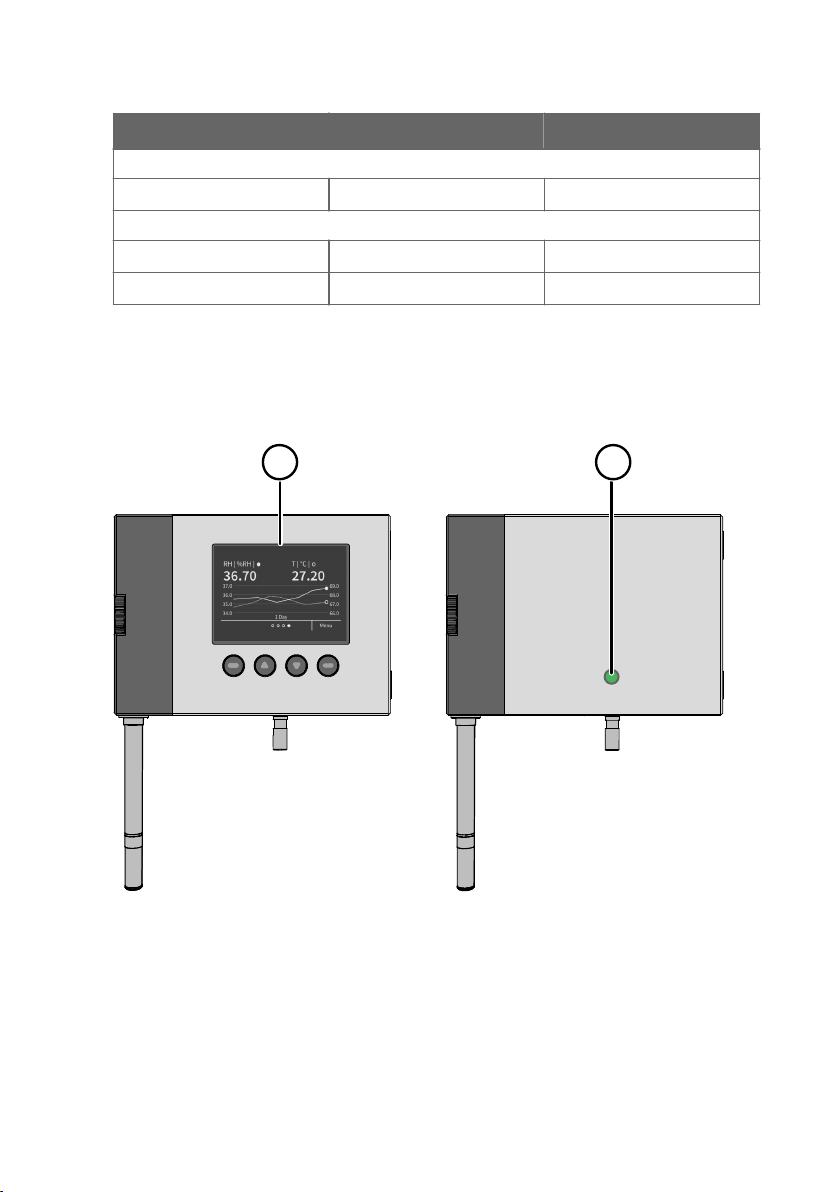
2.5 Display options
The HMT370EX transmitter can be ordered either with a graphical LCD display, or alternatively
without a display. The display options are shown in Figure 1 (page 11).
Figure 1 HMT370EX transmitter display options
Transmitter with display: LCD display with 4-button interface
1
2 Transmitter without display: LED status indicator
11
Page 14

HMT370EX User Guide M212305EN-A
In the display model, probe and transmitter configuration can be carried out either using the
4-button interface of the display, or by connecting the probe or transmitter to Vaisala Insight
PC software. In the model without display, all configuration must be carried out with Vaisala
Insight PC software.
For information on Vaisala Insight PC software, see Vaisala Insight PC software (page 55).
For information on the display interface, see Local display overview (page 46).
2.5.1 LED states in transmitter with no display
In the transmitter model with no display, the status LED indicator on the front of the
transmitter provides a visual indication of the transmitter's status. If the transmitter LED status
indicates that notifications or error messages exist, connect to Vaisala Insight PC software to
view status information and carry out any required configuration.
For instructions on connecting to Insight, see Connecting to Insight PC software (page 55).
For an overview of the Insight software, see Vaisala Insight PC software (page 55).
Table 5 LED status indicator states
LED color Meaning
Not lit Power o.
Green, fast blinking Starting up.
Green, not blinking Power on, normal measurement.
Green, slow blinking Notification or warning, normal measurement. Connect to Insight
Red Error. Connect to Insight to view status information and
Red and blinking Critical error. Connect to Insight to view status information and
to view status information and configure.
configure.
configure.
2.6 Connectivity to Vaisala Insight software
The HMT370EX transmitter and HMT370EX series probes can be connected to Vaisala Insight
software either together as one unit or separately with a Vaisala USB cable (see Spare parts
and accessories (page 93)). With the Insight software, you can:
• Calibrate and adjust the measurement.
• Test and adjust the analog outputs.
• Configure analog output parameter selection, scaling, error, and clipping settings.
• Configure environmental compensations, measurement settings, and local display
settings.
• View real-time measurements and device and status information.
12
Page 15
1 2
3
10
7
54
9
8
6
Chapter 2 – Product overview
More information
‣
Connecting to Insight PC software (page 55)
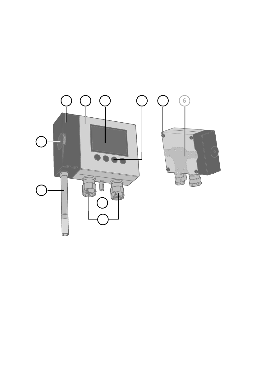
2.7 Transmitter parts
The external parts of the transmitter are shown in Figure 2 (page 13), and the internal parts of
the transmitter are shown in Figure 3 (page 14).
Figure 2 HMT370EX transmitter external parts
Detachable probe body
1
2 Transmitter body (for internal parts, see Figure 3 (page 14))
3 Graphical LCD display (see Display options (page 11))
4 Display interface buttons (see Local display overview (page 46))
5 Wall pads (4 pcs)
6 Retrofit mounting plate for replacing HMT360 installations (optional)
7 Probe body locking wheel
8 Probe head (for information on dierent probe options, see HMT370EX probe options
overview (page 21))
9 Grounding terminal
10 Lead-throughs for wiring (for lead-through accessory options, see Cable gland and
conduit options (page 14))
13
Page 16
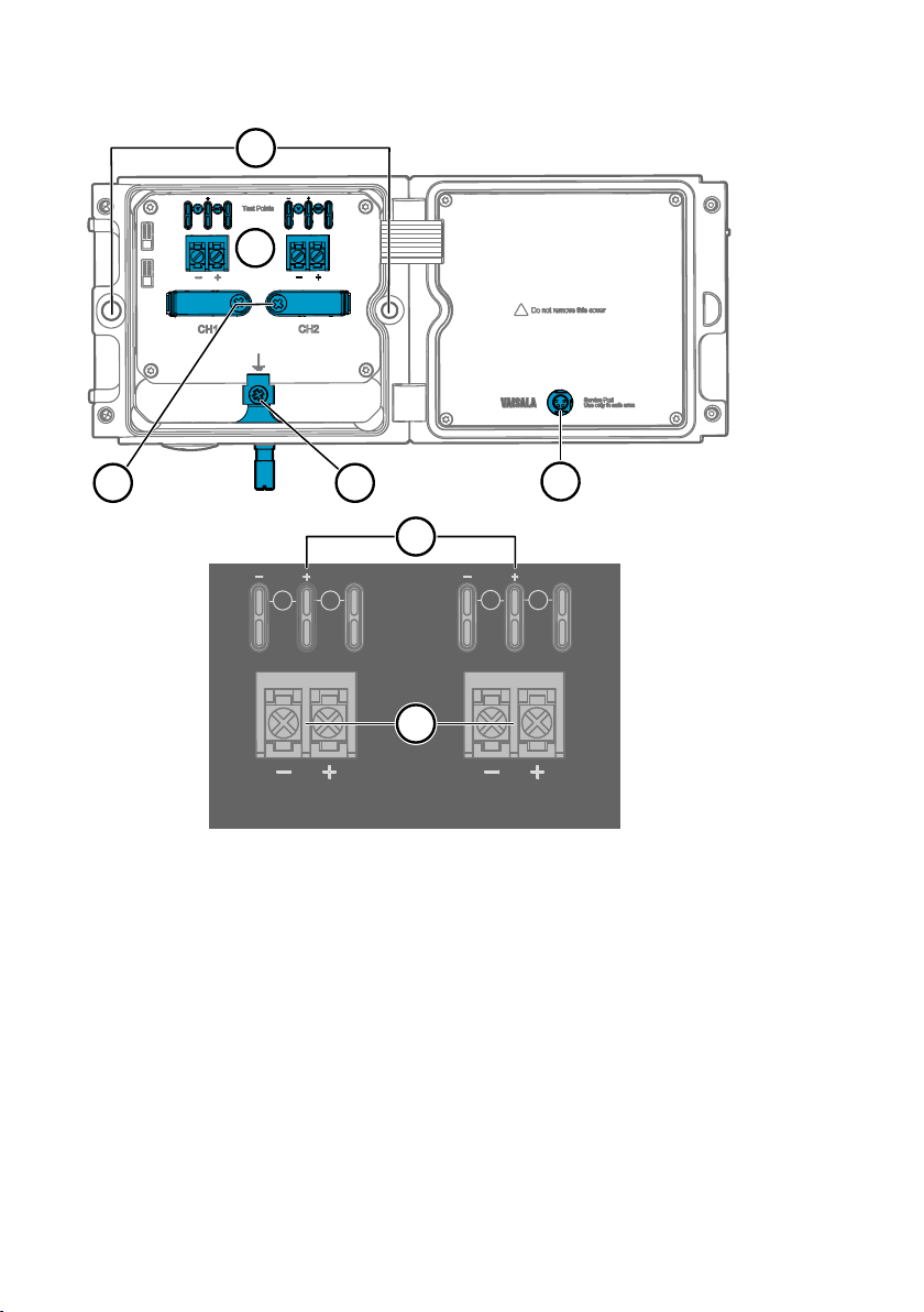
2
mA
Test Points
CH1
CH2
mA
V
V
2a
2b
3 4
1
5
HMT370EX User Guide M212305EN-A
Figure 3 HMT370EX transmitter internal parts
Holes for mounting screws
1
2 Screw terminals and output test points: see 2a and 2b
2a Analog output channel 1 and 2 multimeter test points for current and voltage
2b Screw terminals for wiring analog output channels 1 and 2
3 Cable fastening clamps
4 Transmitter grounding terminal
5 Transmitter service port (M8, requires Vaisala USB cable accessory)
2.7.1 Cable gland and conduit options
The HMT370EX transmitter body has two M20x1.5 lead-throughs that can be fitted with cable
glands, conduit fittings, and plugs, as required by your application. By default, the transmitter
comes delivered with 2 dierent plug types on the transmitter lead-throughs as shown in
Figure 4 (page 15).
14
Page 17
1
2
Chapter 2 – Product overview
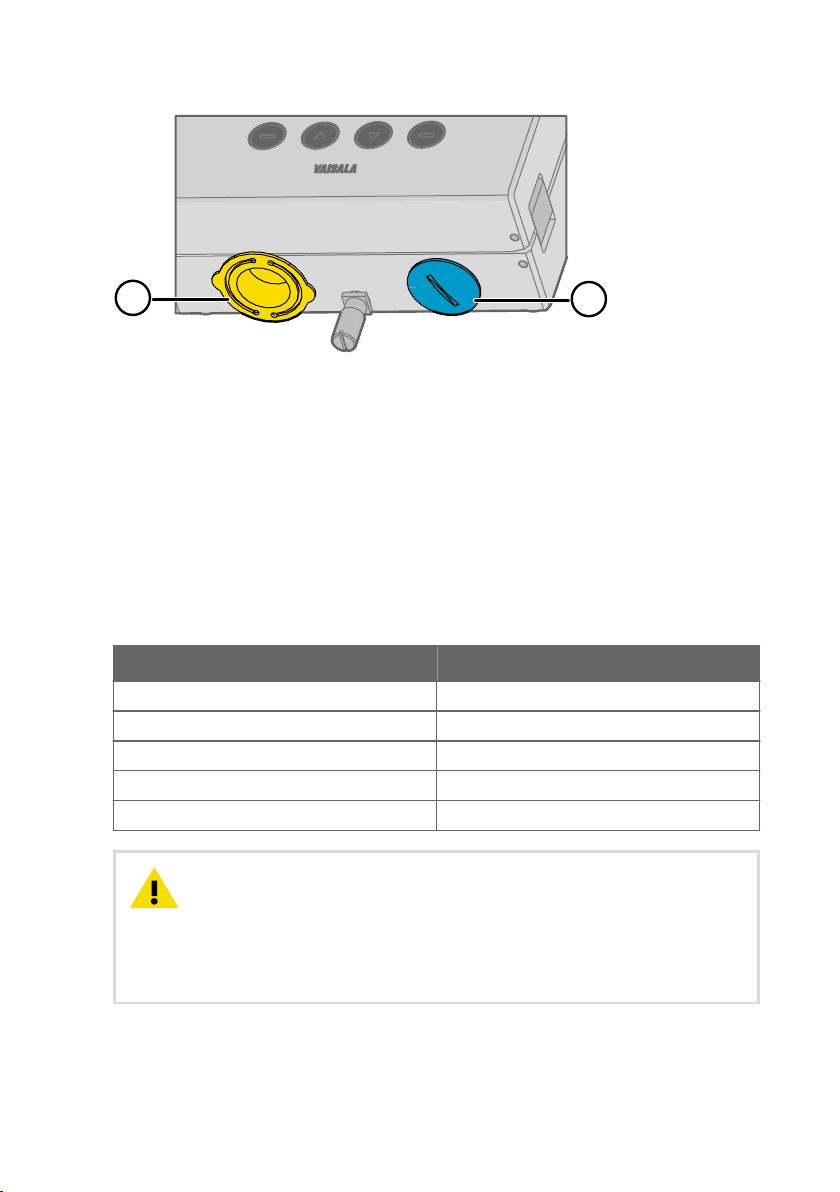
Figure 4 Default plugs in HMT370EX lead-throughs
1 Removable plastic transport cover: must be replaced (fold sides of transport cover
together and pull out)
2 Metal sealing plug: can be used in final installation
The plastic transport cover (1) must always be replaced with an Ex compliant cable gland,
conduit, or seal when wiring HTM370EX. The metal sealing plug (2) can be left in place and
used in the final installation, if the right-hand lead-through is not used.
Cable glands, conduits, and plugs are available from Vaisala as accessories (listed in Table 6
(page 15)).
Table 6 Cable lead-through accessories
Accessory Vaisala item code
Cable gland M20 x 1.5 for Ø 5 … 11 mm cable 265207SP
Cable gland M20 x 1.5 for Ø 10 … 14 mm cable 265208SP
Conduit fitting M16 265243SP
Conduit fitting NPT1/2" 265240SP
Dummy plug (Ex, 2 pcs) 254931SP
CAUTION!
If you use lead-through accessories not ordered from Vaisala, note
the following requirements:
• The cable glands and cables used for wiring the device must not impair the Ex
protection.
• Unused lead-throughs must be sealed using Ex compliant plugs.
• The glands and plugs must be water and dust tight (minimum IP rating: IP54).
15
Page 18
HMT370EX User Guide M212305EN-A
2.8 Using HTM370EX Series transmitters in hazardous locations
WARNING!
Protected installation using galvanic isolators or Zener barriers is
mandatory in a hazardous environment.
In hazardous environments, always connect the transmitters via galvanic isolators or Zener
barriers. A galvanic isolator or Zener barrier must also be used when the transmitter and probe
body are in a safe area, but the probe head is installed in a hazardous environment. For wiring
information, see the galvanic isolator and Zener barrier wiring diagrams included in this
document.
HMT370EX does not include a galvanic isolator or a Zener barrier. They can be ordered as
optional accessories from Vaisala.
WARNING!
HMT370EX series transmitters have been designed for use in
hazardous locations as specified by the product classification. The personnel
installing, using, or maintaining HMT370EX transmitters are responsible for
determining the appropriate protection concept for the specific application
HMT370EX is used in, and that the hazardous area classification of the device
meets the requirements of the application.
WARNING!
If the equipment is used in a manner not specified by Vaisala, the
protection provided by the equipment may be impaired.
HMT370EX series transmitters are certified for use in hazardous areas as defined by the
following classifications:
Table 7 HMT370EX series hazardous area classifications
Certification HMT370EX classification
IECEx 1) / ATEX
1) International certification
2) EU certification
16
2)
II 1 G Ex ia IIC T4 Ga
II 1 D Ex ia IIIC T
-40 °C ≤ T
≤ +60 °C
amb
200
85 °C Da
Page 19
HMT370EX
1 2 31a
M20x1.5 M20x1.5
Chapter 2 – Product overview
CAUTION!
transmitters must have the required competencies for working in the hazardous
location, as defined by the applicable standards.
For information on the standards that apply to using HMT370EX based on the classification of
the device, see HMT370EX certification documentation and the declarations of conformity
related to HMT370EX at www.vaisala.com/declarationofconformity.
The personnel installing, operating, and maintaining HMT370EX
2.8.1 Guidelines for safe use in hazardous conditions
HMT370EX Series parts overview
Figure 5 HMT370EX parts overview
HMT370EX Series transmitters consist of 3 main parts: the transmitter body, a detachable
probe body, and a probe head attached to the probe body, either directly or using a cable.
Figure 5 (page 17) shows the main parts.
Probe heads (for variant descriptions, see HMT370EX User Guide)
1
1a Probe head filters
2 Probe body
3 Transmitter body
17
Page 20
HMT370EX User Guide M212305EN-A
The dierent probe head variants are designed for a range of applications, and have their own
specifications. Ensure that the transmitter body, probe body, and probe head are each placed
in an environment that matches the specification of the part. For allowed ambient temperature
ranges, see Table 8 (page 18).
Table 8 Allowed ambient temperature ranges
Equipment part Allowed ambient temperature range
Transmitter body -40 °C … +60 °C (-40 … +140 °F)
Probe body -40 °C … +60 °C (-40 … +140 °F)
Probe heads HMP374, HMP375, HMP377, and
HMP378
Probe head HMP371 Temperature class T4:
Probe head HMP373 Temperature class T4:
Temperature class T4:
-70 °C … +120 °C (-94 … +248 °F)
Temperature class T3:
-70 °C … +180 °C (-94 … +356 °F)
-40 °C … +60 °C (-40 … +140 °F)
Rubber cable version:
-40 °C … +80 °C (-40 … +176 °F)
FEP cable version:
-40 °C … +120 °C (-40 … +248 °F)
2.8.1.1 Specific conditions of use
CAUTION!
With the installation of the equipment in Zone 0 Group II area it has
to be ensured that sparks due to impact or friction do not occur.
Wiring requirements
• The cable glands and cables used for wiring the device must not impair the Ex protection.
• Unused lead-throughs must be sealed using Ex compliant plugs.
• Select a strain relief option that suits the application (either use cable glands that include
strain relief or install separate clamps: see IEC 60079-14).
CAUTION!
Connect only de-energized wires. Never switch on the power supply
input before completing the wiring and closing the transmitter body.
18
Page 21
mA
V
mA
V
CH1
CH2
A
Service Port
Use only in safe area
!
Do not remove this cover
1
2
Test Points
Chapter 2 – Product overview
Intrinsic safety
The overvoltage category of HMT370EX transmitters is I (non-mains equipment), and ambient
pollution degree is 4, as specified in IEC 60664-1. For intrinsically safe input parameters, see
Table 9 (page 19) .
Table 9 Intrinsically safe input parameters
Parameter Value Associated apparatus entity
parameters
U
i
I
i
P
i
C
i
L
i
28 VDC Uo ≤ U
100 mA Io ≤ I
700 mW Po ≤ P
i
i
i
12.1 nF Co ≥ Ci + C
16 µH Lo ≥ Li+ L
cable
cable
Using analog output test points
There are test points for measuring the voltages and currents of the analog outputs, located
above each screw terminal block as shown in Figure 6 (page 19). Accessing the test points on
the component board requires opening the transmitter enclosure.
Figure 6 Location of test points and service port
Multimeter test points for analog output channels 1 and 2
1
2 Service port for PC connection
19
Page 22
HMT370EX User Guide M212305EN-A
CAUTION!
The transmitter body enclosure must not be opened in an explosion
hazardous area, unless a safe work permit has been issued in accordance with
the standard IEC 60079-14. Either remove the transmitter from the hazardous
area before opening the enclosure, or ensure that an IEC 60079-14 compliant
safe work procedure has been implemented in the hazardous area.
Use an intrinsically safe multimeter that won't cause the intrinsically safe input parameters
listed in Table 9 (page 19) to be exceeded when it is connected in series (current
measurement) or parallel (voltage measurement) to the associated apparatus.
Using the service port
The service port (see Figure 6 (page 19)) must only be used in a safe area. Either remove the
transmitter from the hazardous area or ensure that a safe work procedure has been
implemented in the hazardous area. Only use the Vaisala accessory PC connection cable with
the service port.
Maintenance
The probe (includes probe body and head) can be detached and replaced by the user. The
probe head filter (see Figure 5 (page 17)) is also user-replaceable. For other maintenance
requirements, contact Vaisala.
CAUTION!
The probe can be detached and changed when HMT370EX is
powered. Any other live maintenance, including changing the probe head filter,
is not allowed.
The content in this chapter is maintained in the following separately tracked document:
Document ID: M212506EN Revision: A (25 Feb 2021)
20
Page 23
1 2 3 4 5 6
Chapter 3 – Probe options
3. Probe options
3.1 HMT370EX probe options overview
Figure 7 (page 21) shows the dierent probe options available for HMT370EX series
transmitters. The HMP371 fixed probe option uses a probe head that attaches directly to the
probe body. In the other probe options (HMP373, HMP374, HMP375, HMP377, and HMP378),
the probe head is attached to the probe body with a cable.
Figure 7 HMT370EX probe options
HMP371 fixed probe (page 23)
1
2 HMP373 probe for confined spaces (page 23)
3 HMP374 probe for high pressure applications (page 25)
4 HMP377 probe for high humidity applications (page 27)
5 HMP375 probe for high temperature applications (page 26)
6 HMP378 probe for pressurized pipelines (page 28)
6a HMP378 variant: HMP378F probe option for measuring oil moisture and temperature
(page 31)
6b HMP378 variant: HMP378H probe option for measuring fuel moisture and temperature
(page 31)
21
Page 24

HMT370EX User Guide M212305EN-A
More information
‣
Probe installation overview (page 35)
3.1.1 HMT370EX probe accessories
Table 10 (page 22) lists the available accessories for each probe option.
Table 10 HMT370EX probe accessories
Accessory Vaisala item code Models
M12 Indigo USB Adapter cable
accessory for connecting HMT370EX
probes to Insight
Ball valve ISO 1/2 with welding joint
• Pressure range at +20 °C (+68 °F)
0 … 20 bar (0 … 290 psia) (during
installation max. 10 bar (145 psia)
Duct installation kit 210697 HMP373, HMP377
Mounting flange 210696 HMP375
Cable gland M20 x 1.5 with split seal HMP247CG HMP373, HMP375, HMP377
Fitting body M22 x 1.5 17223SP HMP374
Fitting body NPT1/2 17225SP HMP374
Fitting body ISO1/2 solid structure DRW212076SP HMP378
Fitting body NPT1/2 solid structure 212810SP HMP378
Swagelok fitting for 12 mm probe, 1/2"
NPT thread
Swagelok fitting for 12 mm probe, 3/8"
ISO thread
Swagelok fitting for 12 mm probe, 1/2"
ISO thread
Thread adapter ISO 1/2" to NPT 1/2" 210662SP All models
Manual press HM36854SP HMP378/F/H
USB2 All models
BALLVALVE-1 HMP378
SWG12NPT12 HMP377
SWG12ISO38 HMP377
SWG12ISO12 HMP377
22
Page 25
[1.61]
ø12 [0.47]
86 (3.39)
55.5 [2.19]
53 [2.09]
127 [5]
41
ø 12 (0.47)
37.5 (1.48)
98.5 (3.88)
Chapter 3 – Probe options
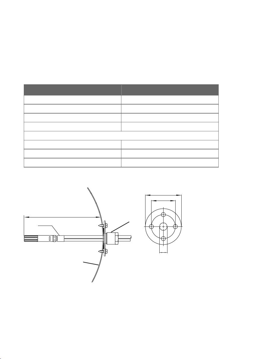
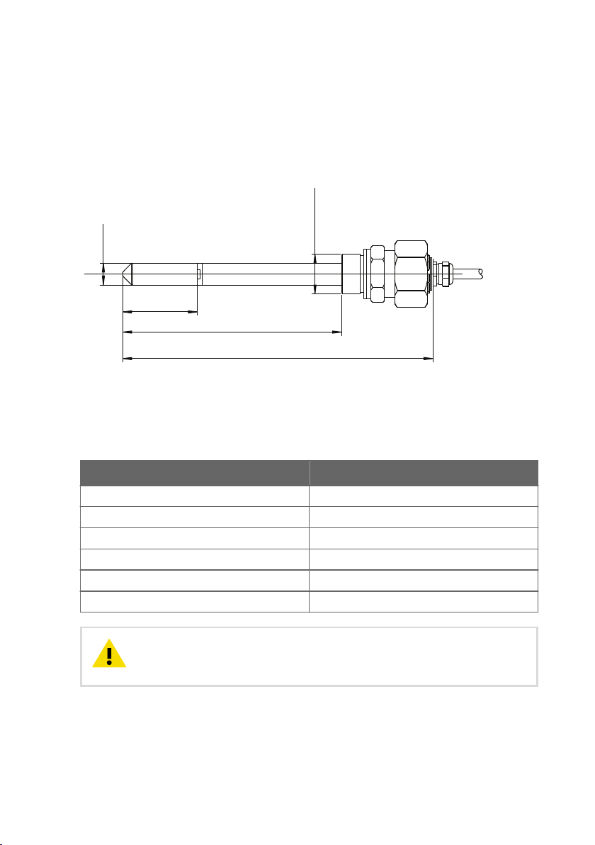
3.2 HMP371 fixed probe
Dimensions
The HMP371 fixed probe option has a probe head that attaches directly on the probe body,
making it suitable for wall mounting applications.
Figure 8 Dimensions in mm (inches)
Specifications
Table 11 HMP371 for wall mounting
Property Description/value
Temperature range -40 … +60 °C (-40 … +140 °F)
Probe diameter 12 mm (0.47 in)
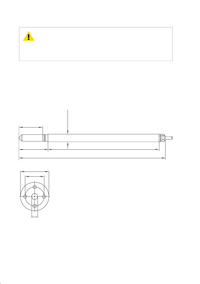
3.3 HMP373 probe for confined spaces
Dimensions
HMP373 is a small size (ø = 12 mm) general-purpose probe that is suitable for installation into
confined spaces such as ducts and channels using the duct installation kit available from
Vaisala (item code 210697: see Figure 10 (page 24)).
Figure 9 Dimensions in mm (inches)
23
Page 26
Ø12 (0.47)
adjustable
duct wall
flange
drilling 16...22
50 (1.97)
75 (2.96)
(0.63...0.87)
HMT370EX User Guide M212305EN-A
Specifications
The HMP373 probe option has 2 operating temperature range options depending on the cable
selected for the probe. The rubber cable option has a temperature range of -40 … +80 °C
(-40 … +176 °F). With the Teflon cable option, the temperature range is -40 … +120 °C
(-40 … +248 °F).
Table 12 HMP373 for confined spaces
Property Description/value
Temperature range with teflon cable -40 … +120 °C (-40 … +248 °F)
Temperature range with rubber cable -40 … +80 °C (-40 … +176 °F)
Probe cable length 2, 5 or 10 meters (6 ft 7 in, 16 ft 5 in, 32 ft 10 in)
Probe diameter 12 mm (0.47 in)
Installation
Duct installation kit 210697
Cable gland M20x1.5 with splitting seal HMP247CG
Swagelok for 12mm probe, 1/2" NPT thread SWG12NPT12
Duct installation kit 210697
Figure 10 Left: Installation kit for duct mounting. Right: Installation flange. Aluminum or stainless
steel.
24
Page 27
M22×1.5 or
NPT 1/2"
120 (4.72)
170 (6.69)
41 (1.61)
ø12 (0.47)
Chapter 3 – Probe options
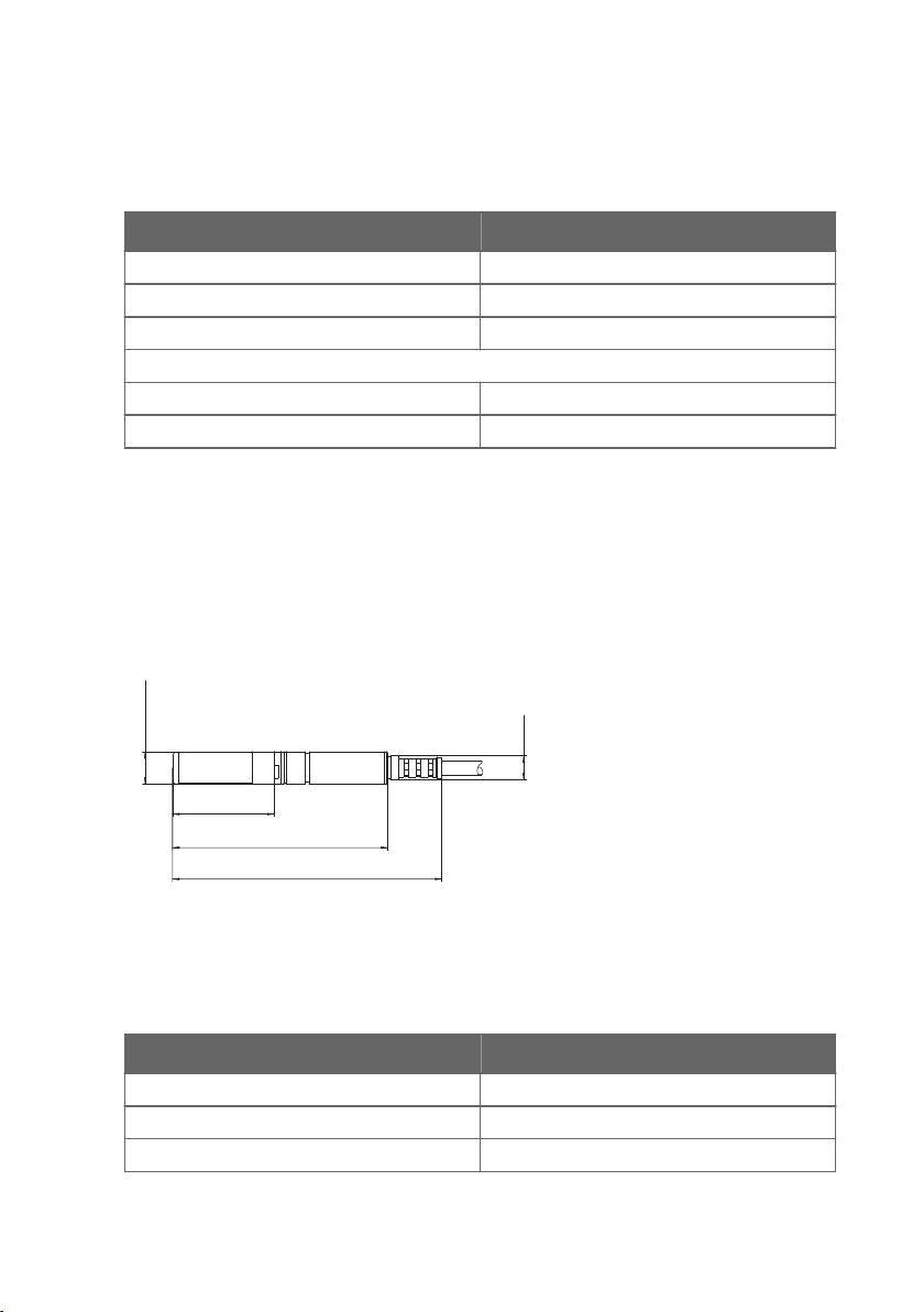
3.4 HMP374 probe for high pressure applications
Dimensions
The HMP374 probe option is designed for measurement in pressurized spaces or vacuum
chambers.
Figure 11 Dimensions in mm (inches)
Specifications
Table 13 HMP374 for high pressure
Property Description/value
Temperature range -70 … +180 °C (-94 … +356 °F)
Pressure range 0 … 10 MPa
Probe cable length 2, 5 or 10 meters (6 ft 7 in, 16 ft 5 in, 32 ft 10 in)
Probe diameter 12 mm (0.47 in)
Fitting body M22x1.5 17223
Fitting body NPT1/2 17225
CAUTION!
carefully when installing to prevent the loosening of the probe by the action of
pressure.
In pressurized processes it is essential to tighten the probe very
25
Page 28
41 (1.6)
51 (2.0)
ø13.5 (0.53)
192 (7.56)
253 (9.96)
drilling 16...22 (0.63...0.87)
50 (1.97)
75 (2.96)
HMT370EX User Guide M212305EN-A
CAUTION!
from normal atmospheric pressure, you must enter the pressure value of the
process as an environmental compensation in order to receive accurate
measurement results. For information on entering environmental compensations
with the transmitter display interface or Vaisala Insight PC software, see
Environmental compensation and measurement settings overview (page 66).
When HMP374 is installed in a process with a pressure diering
3.5 HMP375 probe for high temperature applications
The HMP375 probe option is designed for measurement in high temperature environments.
Dimensions
Figure 12 HMP375 probe and stainless steel installation flange. Dimensions in mm (inches).
26
Page 29
ø 12 (0.47)
37.5 (1.48)
79.5 (3.13)
99.5 (3.92)
M9×1
Chapter 3 – Probe options
Specifications
Table 14 HMP375 for high temperature
Property Description/value
Temperature range -70 … +180 °C (-94 … +356 °F)
Probe cable length 2, 5 or 10 meters (6 ft 7 in, 16 ft 5 in, 32 ft 10 in)
Probe diameter 13.5 mm (0.53 in)
Installation
Mounting flange 210696
Cable gland M20x1.5 with splitting seal HMP247CG
3.6 HMP377 probe for high humidity applications
The HMP377 probe option is constructed to be installed in environments with high humidities.
The same duct installation kit that is used with HMP373 can be used with HMP377: see Figure
10 (page 24).
Dimensions
Figure 13 Dimensions in mm (inches)
Specifications
Table 15 HMP377 for high humidities
Property Description/value
Temperature range -70 … +180 °C (-94 … +356 °F)
Probe cable length 2, 5 or 10 meters (6 ft 7 in, 16 ft 5 in, 32 ft 10 in)
Probe diameter 12 mm (0.47 in)
27
Page 30

HMT370EX User Guide M212305EN-A
Property Description/value
Installation
Duct installation kit 210697
Cable gland M20x1.5 with splitting seal HMP247CG
Swagelok for 12 mm probe, 3/8" ISO thread SWG12ISO38
Swagelok for 12 mm probe, 1/2" NPT thread SWG12NPT12
3.7 HMP378 probe for pressurized pipelines
The HMP378 probe option is especially suitable for measurements inside pipelines. Due to its
sliding fit (available probe lengths: 226 mm and 448 mm (8.90 in/17.6 in)), HMP378 is easy to
install into and remove from a pressurized process. A ball valve kit (Vaisala item code:
BALLVALVE-1) is available for connecting the probe to a pressurized process or pipeline: see
Attaching ball valve kit to process (page 30).
HMP378F and HMP378H probe variants for measuring oil and
fuel moisture
The HMP378F and HMP378H probe options are variants of the standard HMP378, designed for
measurements in oil (HMP378F) and fuel (HMP378H). They provide a specialized selection of
measurement parameters (see Table 4 (page 10)) intended specifically for oil and fuel
measurements. With HMP378F, oil-specific calculation coecients can be configured into use
to customize the measurement for a specific oil type: see Configuring calculation coecients
(page 69).
For more information on HMP378F, see HMP378F probe option for measuring oil moisture and
temperature (page 31).
For more information on HMP378H, see HMP378H probe option for measuring fuel moisture
and temperature (page 31).
28
Page 31

R1/2”ISO7/1 or NPT1/2”
Ø 13.5 (0.53)
35 (1.37)
Ø 12 (0.47)
14 (0.55)
35 - 157/379 (1.37 - 6.2/14.9) (user adjustable)
188/410 (7.40/16.1)
226/448 (8.90/17.6)
Length for standard/optional probes
Chapter 3 – Probe options
Dimensions
Figure 14 Dimensions in mm (inches)
Specifications
Table 16 HMP378 for pressurized pipelines
Property Description/value
Temperature range -70 … +180 °C (-94 … +356 °F)
Pressure range 0 … 4 MPa
Probe cable length 2, 5 or 10 meters (6 ft 7 in, 16 ft 5 in, 32 ft 10 in)
Probe diameter 13.5 mm/12 mm (0.53 in/0.47 in)
Available probe lengths 226 mm/448 mm (8.90 in/17.6 in)
Installation
Fitting body ISO1/2 solid structure DRW212076SP
Fitting body NPT1/2 solid structure NPTFITBODASP
Ball valve ISO 1/2 with welding joint BALLVALVE-1
29
Page 32

G1/2
ISO 228/1
Ø21.5 (drilling)
Ø14
Ø14
Ø14
2
3
4
5
1
HMT370EX User Guide M212305EN-A
3.7.1 Attaching ball valve kit to process
1 Ball valve handle: must point to the same direction as the ball valve body when installing.
2 Extension nipple, threads G1/2 ISO228/1 and R1/2 ISO7/1.
3 Ball valve body. When tightening the assembly, turn only from the ball valve body.
4 Ball of the ball valve.
5 Welding joint, threads R1/2 ISO7/1.
30
Page 33

Chapter 3 – Probe options
1. Attach the welding joint to the process pipe or chamber.
2. Apply a sealant (MEGA-PIPE EXTRA No. 7188 or LOCTITEâ No. 542 with activator No.
7649) on the threads of the welding joint and screw the bottom of the ball valve onto the
welding joint.
3. Tighten the ball valve assembly by turning from the ball valve body.
CAUTION!
Tightening the ball valve kit by turning the extension nipple
can break the sealing. Tighten the ball valve assembly only from the ball
valve body.
4. If you need to cap the ball valve assembly before installing or after removing the probe,
attach a blanking nut to close the top of the valve.
3.7.2 HMP378F probe option for measuring oil moisture and temperature
The HMP378F probe option is a variant of the standard HMP378, designed for measurements
in oil. The mechanics of the probe are the same as in the standard HMP378 probe option (see
HMP378 probe for pressurized pipelines (page 28)).
HMP378F uses the HUMICAPâ L2 sensor designed specifically for oil and fuel measurements.
For L2 sensor specifications, see Table 20 (page 85).
If required, oil-specific calculation coecients can be configured into use to customize
HMP378F measurements. For instructions, see Configuring calculation coecients (page 69).
The following measurement parameters are available for HMP378F:
Table 17 HMP378F measurement parameters
Parameter Abbreviation Unit
Temperature T °C (°F)
Relative saturation RS %RS
Water activity a
Water concentration in oil H2O (oil) ppm
w
w
3.7.3 HMP378H probe option for measuring fuel moisture and temperature
The HMP378H probe option is a variant of the standard HMP378, designed for measurements
in fuel. The mechanics of the probe are the same as in the standard HMP378 probe option (see
HMP378 probe for pressurized pipelines (page 28)).
31
Page 34

HMT370EX User Guide M212305EN-A
HMP378H uses the HUMICAPâ L2 sensor designed specifically for oil and fuel measurements.
For HUMICAP L2 sensor specifications, see Table 20 (page 85).
The following measurement parameters are available for HMP378H:
Table 18 HMP378H measurement parameters
Parameter Abbreviation Unit
Temperature T °C (°F)
Relative saturation RS %RS
Water activity a
w
Water concentration in fuel H2O (fuel) ppm
Saturation temperature T
s
w
°C (°F)
32
Page 35

A
Chapter 4 – Installation
4. Installation
4.1 HMT370EX installation overview
Figure 15 (page 33) shows an example HMT370EX installation using the HMP373 probe with
the probe head mounted with a bracket, and with both lead-throughs fitted with cable glands.
Figure 15 Example wall installation with HMP373 probe
CAUTION!
requirements in this installation overview and the hazardous area safety section
Guidelines for safe use in hazardous conditions (page 17).
WARNING!
ensure that an IEC 60079-14 compliant safe work procedure has been
implemented in the hazardous area.
Before starting the installation, review the equipment and safety
The installation must be carried out in a safe area, or you must
33
Page 36

HMT370EX User Guide M212305EN-A
WARNING!
be opened in a hazardous area. The probe can be detached and changed
when HMT370EX is powered. Any other live maintenance, including changing
the probe head filter, is not allowed.
• Screws for mounting the transmitter:
• Installation directly through the transmitter body: 2 pcs Ø 5.5 mm screws
• Installation with optional mounting plate: 4 pcs Ø 5.5 mm screws and 2 pcs
• Crosshead screwdriver for transmitter cover captive screws and wiring screw
terminals
• Flathead screwdriver for the grounding terminal
• Cable glands, conduits, and plugs as required in your application, and suitable
tools for attaching and tightening them
• Wire-cutting pliers
Optional:
• Crimping tool and wire ferrules
• Allen key (5 mm) for probe body locking wheel
• Ex-compliant multimeter for testing analog outputs
When HMT370EX is powered, the transmitter enclosure must not
M6 Allen screws
4.1.1 Installation preparations
Before starting the installation, check the following:
• Make sure that your installation site suits the Ex classification of the transmitter: see Table
7 (page 16).
• Review the hazardous area information in Guidelines for safe use in hazardous conditions
(page 17) for further information on Ex safety requirements related to HMT370EX and
specific conditions of use.
• When selecting the cable glands and plugs for your application, review the information in
Cable gland and conduit options (page 14).
• Review the wiring diagrams included in this document for information on wiring using
either a galvanic isolator or a Zener barrier.
• Wiring with galvanic isolators (page 40)
• Wiring with Zener barriers (page 41)
34
WARNING!
mandatory in a hazardous environment.
CAUTION!
(CH1) must always be wired. The transmitter receives power through the
Channel 1 screw terminals, and does not power on if only Channel 2 (CH2) is
wired.
Protected installation using galvanic isolators or Zener barriers is
When planning the wiring of your application, note that Channel 1
Page 37

A
mm
[in]
160 [6.3]
35.5
[1.4]
124.5 [4.9]
115 [4.53]
59 [2.3]
56.5 [2.2]
141 [5.5]
115 [4.53]
141 [5.5]
Chapter 4 – Installation
4.1.2 Probe installation overview
Figure 16 Duct installation example with HMP373 probe and duct installation kit
HMT370EX transmitters can be used with 6 dierent probe options that are designed for a
variety of applications. The installation options vary from wall mounting (fixed HMP371 probe
option) to, for example, duct installations (as shown in the HMP373 example in Figure 16
(page 35)) and ball valve installations (HMP378 probe option for pressurized pipelines).
The dierent probe options have varying operating environment specifications, installation
methods, and installation accessories depending on their intended applications. For more
information on each option, see HMT370EX probe options overview (page 21). Also review the
safety information related to allowed ambient temperature ranges for probes before
installation: see Table 8 (page 18).
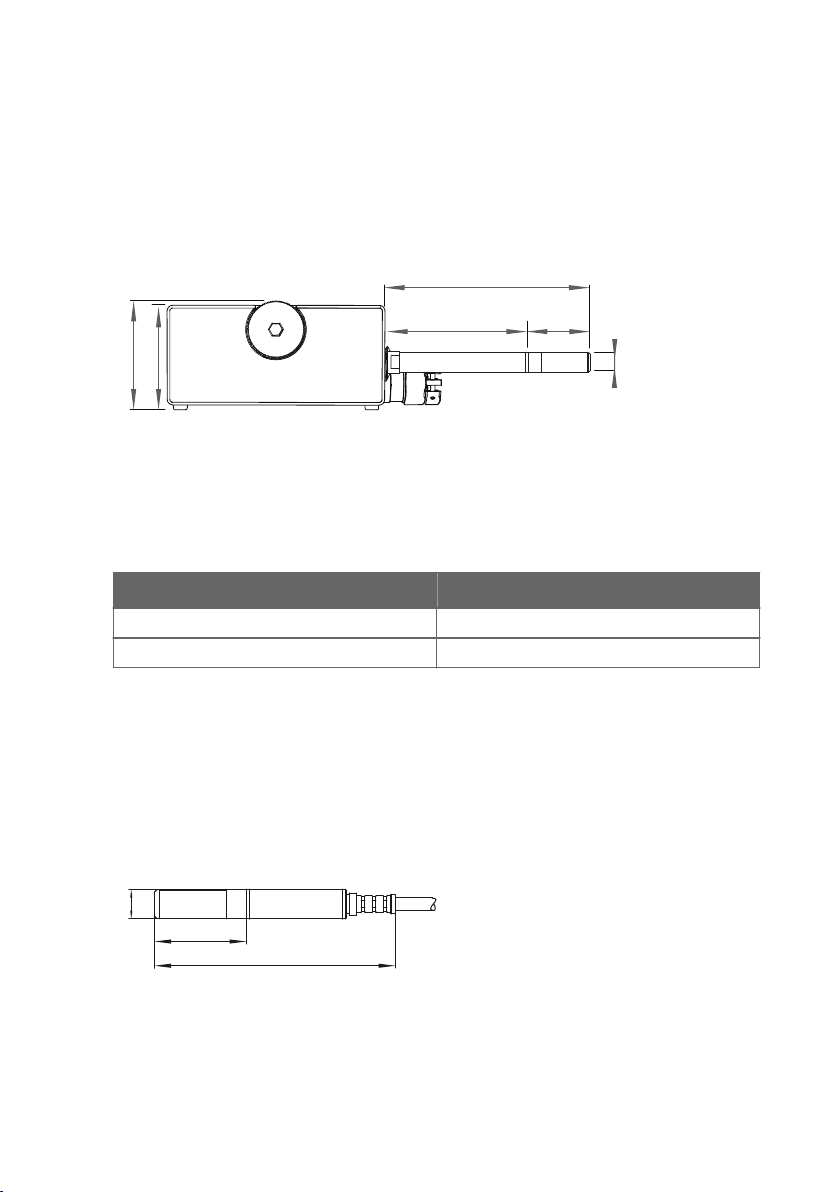
4.1.3 HMT370EX transmitter dimensions
Figure 17 HMT370EX transmitter dimensions
35
Page 38

2 ×
Ø 5 mm
[0.2 in]
HMT370EX User Guide M212305EN-A
4.2 Mounting
Figure 18 Mounting HMT370EX directly through the transmitter body
Select a surface (for example, a wall) for installing the transmitter. You can mount the
transmitter directly to the installation surface with 2 screws, or use an optional mounting plate
that attaches to the back of the transmitter.
1. Detach the probe body from the transmitter body, loosen the captive screws on the
transmitter cover, and open the cover.
36
Page 39

M6
4 ×Ø 5.5 mm
M6
Chapter 4 – Installation
2. Mount the transmitter body on the installation surface either directly through the
transmitter body, or using the optional HMT360 retrofit mounting plate:
a. Installation without mounting plate: attach the transmitter body directly to the
installation surface with 2 Ø 5.5 mm screws as shown in Figure 18 (page 36). The lefthand screw hole has extra vertical space for adjusting the position of the transmitter
after you have attached the right-hand screw.
b. Installation with mounting plate: attach the mounting plate to the installation surface
with 4 Ø 5.5 mm screws, and then attach the transmitter to the mounting plate with 2
M6 Allen screws.
4.3 Attaching cable glands and conduit fittings
The HMT370EX transmitter body has 2 lead-throughs (M20x1.5) for wiring. The combination of
cable glands, conduit fittings, and plugs used in the lead-throughs is application-specific, and
must be determined by the customer. For information on lead-through accessories available
from Vaisala and lead-through accessory requirements, see Cable gland and conduit options
(page 14).
CAUTION!
the following requirements:
• The cable glands and cables used for wiring the device must not impair the Ex
protection.
• Unused lead-throughs must be sealed using Ex compliant plugs.
• The glands and plugs must be water and dust tight.
If you use lead-through accessories not ordered from Vaisala, note
37
Page 40

M20×1.5
M20×1.5
HMT370EX User Guide M212305EN-A
1. Install the application-specific lead-through accessories and lead the wiring cables
through them into the transmitter body: an example is shown below.
4.4 Wiring
38
WARNING!
mandatory in a hazardous environment.
Galvanic isolators and Zener barriers are available from Vaisala as accessories. See
Spare parts and accessories (page 93).
CAUTION!
minimum voltage in all conditions, measured at the transmitter screw terminals.
If the supply voltage is less than 12 V DC, the analog output current can be
erroneous.
It is recommended to use ferrules on the stripped wires to help ensure a secure
connection with the screw terminals.
Protected installation using galvanic isolators or Zener barriers is
Ensure that the transmitter is powered correctly. 12 V DC is the
Page 41

4 – 20 mA
−
+
−
+
CH 1
4 – 20 mA
CH 2
12 – 28 V
Chapter 4 – Installation
Figure 19 Wiring example using one cable
1. Prepare the cabling wires as required in your application (cabling either through 1 or 2
lead-throughs).
a. Strip the cable wires: it is recommended to attach ferrules to the contact ends of the
wires.
b. Open the cable gland and insert a suitable length of the cable inside the transmitter
through the cable gland.
c. Tighten the cable gland: refer to the instructions of the glands used in your
application for maximum tightness.
d. If your installation does not require using both lead-throughs, plug the unused lead-
through with an Ex compliant seal.
2. Connect the screw terminal wiring as required in your application. For protected
installation wiring diagrams, see Wiring with galvanic isolators (page 40) and Wiring
with Zener barriers (page 41).
a. Open the cable fastening clamps below the screw terminals and lead the cables to the
terminals through the clamps.
b. Connect the wires to the screw terminals: for an example, see Figure 19 (page 39).
Note that Channel 1 (CH1) must always be wired. The transmitter receives
power through the CH1 screw terminals, and does not power on if only
Channel 2 (CH2) is wired.
c. Adjust the length of the wires and close the cable fastening clamps so that they hold
the cables in place.
39
Page 42

mA
Test Points
mA
V
V
HAZARDOUS AREA
External
grounding
terminal
SAFE AREA
4 ... 20
mA
+
-
+
-
4 ... 20
mA
+
-
+
-
L
L
+
-
L
L
+
-
Intrinsically
safe certified
galvanic isolators
Controller
DC power supply
+
-
If the controller
uses voltage input,
use a shunt resistor:
+
-
4 ... 20 mA
Controller
U = I*RI
RI
+
-
+
-
HMT370EX User Guide M212305EN-A
4.4.1 Wiring with galvanic isolators
Figure 20 Wiring diagram with galvanic isolators
40
Page 43

4.4.2 Wiring with Zener barriers
mA
Test Points
mA
V
V
HAZARDOUS AREA SAFE AREA
4 ... 20
mA
+-+
-
4 ... 20
mA
Intrinsically
safe certified
Zener barriers
Controller
DC power supply
+
-
+
-
If the controller
uses voltage input,
use a shunt resistor:
+
-
4 ... 20 mA
Controller
U = I*RI
RI
+-+
-
4 ... 20
mA
+
-
External
grounding
terminal
Chapter 4 – Installation
Figure 21 Wiring diagram with Zener barriers
41
Page 44

3.5 Nm
HMT370EX User Guide M212305EN-A
4.5 Finalizing installation: closing transmitter and attaching grounding
1. Close the transmitter body cover and tighten the captive screws. Tighten the screws to
approximately 3.5 Nm: ensure that there is no gap between the covers.
Ensure that the cover has been tightened suciently so that there is no gap
between the covers in the area highlighted in the illustration.
2. Attach the probe body to the transmitter.
42
It is sucient to tighten the probe body to finger tightness with the locking
wheel. To prevent detaching the probe body without tools, you can tighten
the locking wheel further with an Allen key (5 mm).
Page 45

4 mm2
Chapter 4 – Installation
3. Connect the grounding terminal on the bottom of the transmitter to the grounding
element of the installation site with a 4 mm2 grounding wire.
4. After grounding the transmitter, switch on the power supply input.
4.6
Optional: testing analog output level with a
multimeter
CAUTION!
hazardous area, unless a safe work permit has been issued in accordance with
the standard IEC 60079-14. Either remove the transmitter from the hazardous
area before opening the enclosure, or ensure that an IEC 60079-14 compliant
safe work procedure has been implemented in the hazardous area.
Always use an Ex compliant multimeter. The output parameters of the multimeter
must be compatible with the input parameters of the transmitter.
The transmitter body enclosure must not be opened in an explosion
43
Page 46

mA
Test Points
CH1
CH2
mA
V
V
20.0 mA
HMT370EX User Guide M212305EN-A
Figure 22 Multimeter test point overview
If you you want to verify the output level of the analog output channels, test the connection as
follows:
1. Detach the probe body and open the transmitter cover.
2. Connect a multimeter to the mA testing points located above the output screw terminals
on the transmitter component board.
3. Start the output test mode either by using the transmitter display interface, or, if using a
transmitter without a display, by connecting the transmitter to Insight PC software.
a. For instructions on using the output test mode with Insight PC software, see Testing
analog output level with Insight (page 64).
b. To start the output test mode with the display interface, open the Settings > Analog
outputs > Test outputs menu.
c. Select an output level to force the output to (4, 12, or 20 mA) and select Start. Verify
the output with the multimeter.
4. After verifying the output, remove the multimeter, close the transmitter cover, and
reattach the probe body.
44
Page 47

Chapter 4 – Installation
5. If the output is incorrect and requires adjustment, see Analog output adjustment overview
(page 74).
CAUTION!
The service port (see Figure 3 (page 14)) must only be used in
a safe area. Either remove the transmitter from the hazardous area or
ensure that a safe work procedure has been implemented in the hazardous
area. Only use the Vaisala accessory PC connection cable with the service
port.
45
Page 48

A
1 2
3 4
HMT370EX User Guide M212305EN-A
5. HMT370 local display interface
5.1 Local display overview
Figure 23 HMT370EX local display examples: measurement graph view and main menu screen
The display version of the HMT370EX transmitter has graphical LCD display with a 4-button
interface. The local display can be used to view measurement information, configure settings,
and calibrate and adjust measurements and outputs.
Using local display interface buttons
The display interface has 4 buttons for operating the display menus.
Figure 24 HMT370EX display interface buttons
Back: press to move back in the menu tree or cancel a selection.
1
2 Up: move up in the menu tree or increase a value.
3 Down: move down in the menu tree or decrease a value.
4 Select: press to open a menu or confirm a selection.
46
Page 49

Chapter 5 – HMT370 local display interface
Press and hold Back to return directly to the main menu.
Press and hold the Up or Down button to increase or decrease a value faster.
Measurement information views
The home view of the display has several options for showing the measurement information of
the connected probe. You can switch between the dierent views (for example, numerical
parameters or graph view) using the Up and Down buttons. The parameter display settings
can be configured in the Settings > Display menu.
Figure 25 2 parameter view example
Figure 26 Graph view example
47
Page 50

UP
SELECT
BACK
BACK
HMT370EX User Guide M212305EN-A
Figure 27 Parameter list view example
Configuration options
You can configure the following settings with the local display:
• Analog output settings (parameters, scaling, fault indication, output test and adjustment)
• Measurement settings (environmental compensation and filtering factor)
• Display settings (displayed parameters, units, graph visualization options, general display
settings such as timeout and PIN code)
In addition to configuration, you can also calibrate and adjust the measurement of the
connected probe with dierent references (1-point or 2-point adjustment), view device and
measurement status information, and reset the transmitter back to factory settings.
5.1.1 Local display PIN code
You can enable a (non-configurable) PIN code in the Settings > Display menu to prevent using
the display menus without entering the code.
The PIN code is the following 4 button presses: Up > Select > Back > Back
Figure 28 Display PIN code button presses
48
Page 51

Chapter 5 – HMT370 local display interface
5.1.2 Light and dark display themes
Figure 29 Dark (left) and light (right) display theme examples
You can select either a Light or Dark display theme to match the lighting conditions of your
environment.
The Light theme has a light background and dark text and graphics, and the Dark theme has a
dark background and light text and graphics.
5.1.3 Sleep mode
Figure 30 Transmitter display in sleep mode
You can define a timeout after which the display goes to sleep mode when not used with the
Settings > Display > Timeout selection (1, 5, 15, 30, 60 minutes or disabled). Pressing any
button returns the display back to normal operation from the sleep mode.
49
Page 52

HMT370EX User Guide M212305EN-A
5.2 HMT370EX display main menu
Figure 31 HMT370EX display interface main
menu
The first view of the display interface menu contains 4 submenus for dierent configuration
options. See the following sections for more information on each submenu:
• Settings menu (page 50)
• Calibration menu (page 53)
• Status menu (page 53)
• Maintenance menu (page 54)
5.3
Settings menu
Figure 32 Settings menu
The Settings menu contains the following configuration options:
Display
Analog outputs Analog output 1 and 2 parameter selection, scaling, error output
Measurement
settings
50
Selections for which parameters are displayed, display interface
language, graph settings, display PIN code protection, timeout (sleep
mode), and theme.
selection, and output test mode.
Environmental compensation and filtering factor configuration.
Page 53

Chapter 5 – HMT370 local display interface
5.3.1 Display menu
Figure 33 Display menu
In the Display menu, you can select which parameters are shown on the display, change the
local display interface language, and configure graph, unit, display timeout, menu access PIN
code, and color theme options.
Displayed
parameters
Language Set the local display interface language. The available options are English,
Graph Set the measurement parameters shown as graphs and the time period
Units Set the display interface to show units either as metric or non-metric.
Menu PIN
code
Timeout Define the time after which the screen enters power saving mode (sleep
Theme Set the display interface to use either a Light or Dark color theme.
Select which measurement parameters are shown on the display. Up to 4
parameters can be shown simultaneously.
German, French, Japanese, and Chinese.
visualized in the graph.
Enable or disable using the fixed PIN code to restrict access to configuration
menus.
mode) if not used.
If you have selected a wrong language and need to change the display language,
see the instructions in Problems and their possible solutions (page 80). You can
also change the display language by connecting the transmitter to the Insight PC
software.
51
Page 54

HMT370EX User Guide M212305EN-A
5.3.2 Analog outputs menu
Figure 34 Analog output settings
In the Analog outputs menu, you can select the measurement parameters that are sent on
analog output channels 1 and 2, select the output scaling and error indication level, and test
the accuracy of the outputs.
Output 1 Select which measurement is sent on analog output channel 1 and how the
Output 2 The same configuration options as for Output 1.
Test outputs You can force the analog output to a fixed value (options: 4, 12, and 20 mA)
For more information on analog output configuration using the local display or Vaisala Insight
PC software, see Analog output configuration overview (page 61).
measurement value is scaled on the 4 – 20 mA output range. You can also set
the current level that is output to indicate an error state (either 3.6 mA or 21
mA).
and read the fixed output to verify that the transmitter outputs are working
correctly.
5.3.3 Measurement settings menu
In the Measurement settings menu, you can set environmental compensations and configure
the filtering factor.
CAUTION!
accurately measure calculated parameters that require pressure data. By default,
the pressure compensation value is set as 1013.25 hPa.
Pressure Enter the pressure of the current measurement environment (in hPa).
Filtering on/o Enable or disable measurement output filtering using the default
Extended filtering
on/o
Filtering factor Enter a custom filtering factor value (requires enabling the Extended
52
You must enter the pressure compensation value in order to
filtering factor.
Enable or disable measurement output filtering using a custom filtering
factor value (entered in the Filtering factor selection).
filtering factor selection).
Page 55

Chapter 5 – HMT370 local display interface
5.4 Calibration menu
Figure 35 Calibration menu
In the calibration menu, you can adjust the RH or T measurement of the connected probe
using 1 or 2 reference points. You can also view information about the currently existing
adjustments and reset the adjustment of the connected probe back to default.
RH adjustment Relative humidity calibration and adjustment using 1 or 2 reference
T adjustment Temperature calibration and adjustment using 1 or 2 reference points.
Calibration
information
Reset probe Selections for resetting probe measurement adjustments to factory
points.
Shows information on the adjustments made to the measurement.
default settings.
5.5 Status menu
Figure 36 Status menu
53
Page 56

HMT370EX User Guide M212305EN-A
The Status menu contains options for viewing information about the operation of the device:
transmitter and probe status messages, output and measurement status, and general
information on the device.
Device status Device operation information such as notifications and errors.
Output status Shows the current statuses of analog output 1 and 2 (output level and
Measurement status Shows the current status or statuses of each measurement parameter
About Device information (software version and manufacturing date).
measurement).
(for example, OK or Measurement not ready).
5.6 Maintenance menu
Figure 37 Maintenance menu
In the maintenance menu, you can restart the transmitter and restore transmitter settings back
to factory defaults.
Adjustments made to probe measurement will remain in place also after a
transmitter factory reset, as probe adjustments are stored in probe memory.
54
Page 57

Chapter 6 – Operating with Insight PC software
6. Operating with Insight PC software
6.1 Vaisala Insight PC software
Vaisala Insight PC software is a configuration software for Indigo compatible devices. The
supported operating systems are Windows 7 (64-bit), Windows 8.1 (64-bit), and Windows 10
(64-bit).
With the Insight software, you can:
• See device information and status.
• See real-time measurement data.
• Calibrate and adjust device measurement.
• Configure analog output settings such as parameters, scaling and error level, and test and
adjust analog output level.
• Configure environmental compensations and measurement settings such as filtering
factor and calculation coecients.
Download Vaisala Insight software at www.vaisala.com/insight.
The probe body can be detached from the transmitter and connected to Insight separately
using the probe body service port. You can also connect the transmitter and probe body to
Insight together as one unit by using the transmitter service port.
Connecting the probe body separately to Insight software requires the M12 Indigo USB
Adapter accessory (Vaisala item USB2). Connecting the transmitter service port to Vaisala
Insight software requires the M8-4F USB cable accessory (Vaisala item 219690).
6.1.1 Basic and Advanced user modes
You can switch between the Basic Mode and Advanced Mode user modes with the selections
in the Settings menu.
Certain functionalities are only available in Advanced Mode. The options enabled by switching
to Advanced Mode are often intended for administrative users: set the user mode according to
the requirements of the personnel that use the device.
6.2
Connecting to Insight PC software
• Computer with Vaisala Insight PC software installed
• M12 Indigo USB Adapter accessory (Vaisala item USB2) for connecting the
probe body to Insight, or the USB connection cable for transmitter service port
(M8-4F, Vaisala item 219690).
55
Page 58

mA
V
mA
V
CH1
CH2
A
Service Port
Use only in safe area
!
Do not remove this cover
Test Points
M12 (USB2)
M8 (219690)
HMT370EX User Guide M212305EN-A
CAUTION!
The transmitter body enclosure must not be opened in an explosion
hazardous area, unless a safe work permit has been issued in accordance with
the standard IEC 60079-14. Either remove the transmitter from the hazardous
area before opening the enclosure, or ensure that an IEC 60079-14 compliant
safe work procedure has been implemented in the hazardous area.
CAUTION!
When connecting several devices at the same time, note that your
computer may not be able to supply enough power through its USB ports. Use
an externally powered USB hub that can supply >2 W for each port.
Figure 38 Connecting to Insight: probe body and transmitter service port locations
1. If you want to configure the probe by itself:
a. Open the Insight PC software.
b. Connect the M12 USB cable (Vaisala item USB2) to a free USB port on the PC.
c. Detach the probe body from the transmitter: see Mounting (page 36) for an example.
CAUTION!
The probe can be detached and changed when HMT370EX
is powered. Any other live maintenance, including changing the probe
head filter, is not allowed.
d. Move the probe body to the space you are using to connect the probe to a computer.
e. Connect the M12 USB cable (Vaisala item USB2) to the service port of the probe.
f. Wait for Insight to detect the probe.
56
Page 59

Chapter 6 – Operating with Insight PC software
2. If you want to configure the transmitter and probe together as one unit:
a. Open the Insight PC software.
b. Connect the the M8 USB cable (Vaisala item 219690) to a free USB port on the PC.
c. Open the transmitter cover: see Mounting (page 36) for an example.
d. Reconnect the probe body to the transmitter cover.
e. Connect the M8 USB cable (Vaisala item 219690) to the service port on inside of the
the transmitter cover.
f. Wait for Insight to detect the probe.
6.2.1 Installing driver for the USB service cable
Only Windowsâ operating systems are supported by the driver of the USB
service cable.
1. Connect the USB service cable to a USB port on your computer. Windowsâ detects the
new device and installs the appropriate driver.
2. Open Devices and Printers from the Windowsâ Start menu. Use search to find it if
necessary (search for "devices").
3. Locate the cable in the list of devices:
• If the device is listed as Vaisala USB Device with a COM port number in brackets, the
cable is ready for use. Note the COM port number, you will need it later.
• If the device is listed as Vaisala USB Instrument Cable without a COM port number
listed, you must install the driver manually.
57
Page 60

HMT370EX User Guide M212305EN-A
4. To install the driver manually:
a. Disconnect the USB service cable from the computer.
b. Download the Vaisala USB driver at http://www.vaisala.com/software (select the
appropriate USB Instrument Driver Setup for your cable).
c. Run the USB driver installation program Vaisala USB Device Driver
Setup.exe. Accept the installation defaults.
d. Go back to step 1 and verify that the driver installation works as expected.
58
Page 61

1
2
3 4
Chapter 6 – Operating with Insight PC software
6.3 Insight main view with transmitter
Figure 39 Insight main menu and settings: transmitter view
1 Select to access Insight main menu.
• Configure Device: environmental compensation settings, analog output settings,
display and graph settings, measurement coecients, filtering factor, and general
settings.
• Export Settings: creates a text file export of the device settings.
• Calibrate: options for calibrating and adjusting RH and T measurement, adjusting
analog outputs, viewing adjustment data, and restoring factory adjustments.
• Restart device: quick access selection for restarting the device.
• Restore factory settings: restores default settings, clears any user adjustments,
and restores the latest factory calibration.
• Probe: selections for restarting the connected probe and restoring factory settings
to the probe.
• About Device: general device information such as serial number and software
2 Select Settings to switch between the Basic Mode and Advanced Mode user modes,
3 Monitoring provides options for monitoring and recording selected parameters, and
4 Device information menu with the following tabs:
version.
change the units of parameters (metric/non-metric), enter a factory code to access
restricted functionalities, or view information about the Insight software.
exporting the monitoring data as a CSV (comma-separated values) file.
• Measurements: measurement graph view with parameter drop-down selection.
• Calibration information: read-only information about the latest stored calibration.
59
Page 62

HMT370EX User Guide M212305EN-A
• Diagnostics: troubleshooting and administrative information about the device
status. Also includes options for exporting the device error log and other
diagnostics information as files (CSV/ZIP). When contacting Vaisala support, it is
recommended to include an up-to-date export of the error log with the support
request.
6.4 Insight main view with probe
Figure 40 Insight main menu and settings: probe view
When you detach a probe from the transmitter and connect it separately to Insight, the
configuration view is otherwise similar as when connecting a transmitter and a probe together
(see Insight main view with transmitter (page 59)), but the configuration options are limited to
probe functionalities.
60
Page 63

Chapter 7 – Analog output configuration
7. Analog output configuration
7.1 Analog output configuration overview
HMT370EX has 2 scalable 4 – 20 mA analog output channels. Each output has the following
configuration options:
• Output parameter selection
• Output scale low end and high end
• Error output level and clipping limits
• Output testing (force output to a specified level for multimeter testing)
Note that the clipping and error limit configuration can only be carried out with
Insight PC software.
configuration of the outputs can be changed with the transmitter display interface or by
The
connecting the transmitter to Vaisala Insight PC software.
Figure 41 Analog output configuration options in Insight PC software
61
Page 64

HMT370EX User Guide M212305EN-A
7.2 Configuring analog outputs with Insight
Using the Insight PC software, you can configure the measurement parameter sent on each
analog output, the scaling of the parameter, clipping and error limits, and the error output
level. In addition to configuration, you can also carry out an output test where the output is
forced to a fixed level so it can be verified with a multimeter. Both output channels have the
same configuration options.
The analog output configuration view in Insight also shows the status and output mode of the
analog output channel: see Figure 41 (page 61).
1. Connect to Insight (see Connecting to Insight PC software (page 55)).
2. Select > Configure Device, and then one of the 2 analog outputs.
3. Select the measurement parameter that is sent on the output channel you are configuring,
set the scaling for the output, and define the output level that indicates an error.
4. Define the clipping and error limits.
5. Store the selections with Save and exit with Close.
6. Repeat the configuration for each output (analog outputs 1, 2, and 3) as required.
7. If you want to test the output, see the instructions in Analog output level test (page 63).
7.3
Configuring analog outputs with local display
interface
Using the local display interface of the transmitter, you can configure the measurement
parameter sent on each analog output, the scaling of the parameter, and the error output level.
In addition to configuration, you can also carry out an output test where the output is forced to
a fixed level so it can be verified with a multimeter. Both output channels have the same
configuration options.
To view the status of the outputs, select Menu > Status > Output status.
Note that clipping and error limit configuration for the analog outputs can only be
carried out with Insight PC software.
1. Select Menu > Settings > Analog outputs.
2. Select the measurement parameter that is sent on the output channel you are configuring,
set the scaling for the output, and define the output level that indicates an error.
3. Repeat the configuration for each output as required.
4. If you want to test the output, see the instructions in Analog output level test (page 63).
62
Page 65

mA
Test Points
CH1
CH2
mA
V
V
20.0 mA
Chapter 7 – Analog output configuration
7.4 Analog output level test
If you need to verify that the signal from the HMT370EX transmitter's analog output channel is
correct, you can force the output of the channel to a specific value and measure the output
level with a multimeter.
The analog output level tested can be carried out either with the local display interface or
using Vaisala Insight PC software.
Figure 42 Multimeter test point overview
CAUTION!
The transmitter body enclosure must not be opened in an explosion
hazardous area, unless a safe work permit has been issued in accordance with
the standard IEC 60079-14. Either remove the transmitter from the hazardous
area before opening the enclosure, or ensure that an IEC 60079-14 compliant
safe work procedure has been implemented in the hazardous area.
Always use an Ex compliant multimeter. The output parameters of the multimeter
must be compatible with the input parameters of the transmitter.
7.4.1 Testing analog output level with local display interface
If you you want to verify the output level of an analog output channel, test the connection as
follows:
1. Detach the probe body and open the transmitter cover.
2. Connect a multimeter to the mA testing points located above the output screw terminals
on the transmitter component board (see Figure 42 (page 63)).
63
Page 66

HMT370EX User Guide M212305EN-A
3. To start the output test mode with the local display interface, open the Settings > Analog
outputs > Test outputs menu.
4. Select an output level to force the output to (4, 12, or 20 mA) and select Start. Verify the
output with the multimeter and select Finish when done.
5. If the output is incorrect and requires adjustment, see Analog output adjustment overview
(page 74).
6. Remove the multimeter, close the transmitter cover, and reattach the probe body.
7.4.2 Testing analog output level with Insight
1. Detach the probe body and open the transmitter cover.
2. Connect a multimeter to the mA testing points located above the output screw terminals
on the transmitter component board (see Figure 42 (page 63)).
3. Connect to Insight (see Connecting to Insight PC software (page 55)).
4. Select
5. Enter a test output value in the Test output level and select Save.
> Configure Device, and then the analog output channel you want to test.
6. The Output mode field will show that the Test mode is now active.
7. Verify that the multimeter reading matches the Test output level value.
8. If the output is incorrect and requires adjustment, see Analog output adjustment overview
(page 74).
64
Page 67

Chapter 7 – Analog output configuration
9. After verifying the output, clear the value from the Test output level field and select Save.
This switches the Test mode o.
CAUTION!
The Test mode must always be switched o after verifying the
output level to return to normal measurement mode.
10. Remove the multimeter, close the transmitter cover, and reattach the probe body.
65
Page 68

HMT370EX User Guide M212305EN-A
8. Environmental compensation and measurement settings
8.1 Environmental compensation and measurement settings overview
Pressure compensation
You can configure a pressure compensation value to HMT370EX using either the local display
interface or Vaisala Insight PC software.
CAUTION!
accurately measure calculated parameters that require pressure data. By default,
the pressure compensation value is set as 1013.25 hPa.
You must enter the pressure compensation value in order to
Filtering factor
If the measuring environment produces occasional exceptionally high or low readings that
need to be averaged out in the output, you can apply a filtering factor to the measurement
output. The filtering factor defines the speed at which the latest measurement is integrated
into the transmitter's output. For example, setting the filtering factor to 0.500 means that the
displayed output is a 50%+50% combination of the previous measurement and the most
recent measurement. To show the latest measurement directly in the output, set the filtering
factor to 1.000 (no filtering).
HMT370EX has 2 alternative filtering factor options: either a default filtering factor that uses a
13 second moving average (T90), or a custom filtering factor defined by the user.
The filtering factor can be configured using the local display interface or Vaisala Insight PC
software.
Calculation coecients
When required, you can define the molar mass of the ambient gas (default value: 28.965 g/
mol) and oil-specific calculation coecients. The oil-specific calculation coecients
(selections Oil A and Oil B) are applicable only for the HMP378F oil probe model.
CAUTION!
calculating gas dependent humidity parameters.
The molar mass of the ambient gas must be defined when
66
Page 69

Chapter 8 – Environmental compensation and measurement settings
Note that calculation coecients (molar mass of the ambient gas and oil-specific
calculation coecients) can only be entered with Vaisala Insight PC software.
For more information on the oil calculation coecients for HMP378F, see HMP378F calculation
model with average oil coecients (page 69) and HMP378F calculation model with oil-
specific coecients (page 70).
8.2 Configuring pressure compensation
You can configure a pressure compensation value to HMT370EX using either the local display
interface or Vaisala Insight PC software.
Note that configuring these settings requires using Insight in Advanced Mode.
To set a pressure compensation value:
1. If you are using the local display interface:
a. Select Menu > Settings > Measurement settings > Pressure.
b. Use the Up and Down buttons to enter a value for each digit of the pressure value.
Move to the next digit with Select.
c. After the final digit, pressing Select saves the pressure value.
2. If you are using Insight PC software:
a. Connect to Insight PC software: see Connecting to Insight PC software (page 55).
b. Select
c. Enter the pressure compensation value into the Pressure field and select Save.
> Configure Device > Compensation setpoints.
67
Page 70

1
2
3
HMT370EX User Guide M212305EN-A
8.3 Configuring filtering factor
Figure 43 Filtering factor configuration in Insight PC software
1 Enable Filtering on/o to use the default filtering factor.
2 Enable Extended filtering on/o if you want to enter a custom filtering factor value.
3 After enabling the Extended filtering on/o selection, enter the custom value into the
Filtering factor field.
You can apply a filtering factor to the measurement output to average out measurement
output over time (for more information, see Environmental compensation and measurement
settings overview (page 66)). A default or custom filtering factor can be set using either the
local display interface or Vaisala Insight PC software.
To set a filtering factor:
1. If you are using the local display interface:
a. Select Menu > Settings > Measurement settings > Filtering.
b. To enable the default filtering factor (13 second moving average (T90)), set the
Filtering on/o selection to ON.
c. If you want to enter a custom filtering factor, set the Extended filtering on/o
selection to ON, select Filtering factor and enter the custom value with the Up and
Down buttons.
d. After the final digit, pressing Select saves the pressure value.
68
Page 71

Chapter 8 – Environmental compensation and measurement settings
2. If you are using Insight PC software:
a. Connect to Insight PC software: see Connecting to Insight PC software (page 55).
Note that configuring these settings requires using Insight in Advanced
Mode.
b. Select > Configure Device > Filtering.
c. To enable the default filtering factor (13 second moving average (T90)), set the
Filtering on/o selection to ON and select Save.
d. If you want to enter a custom filtering factor, set the Extended filtering on/o
selection to ON, enter the custom value into the Filtering factor field, and select Save.
8.4 Configuring calculation coecients
You can configure a compensation value for the molar mass of the ambient gas and oil-specific
coecients to HMT370EX with Vaisala Insight PC software. The oil-specific coecients (Oil A
and Oil B) are only applicable for the HMP378F oil measurement probe option.
Note that configuring these settings requires using Insight in Advanced Mode.
Note that calculation coecients can only be configured with Insight PC software.
To enter calculation coecient values with Insight:
1. Connect to Insight PC software: see Connecting to Insight PC software (page 55).
2. Select
3. Enter the calculation coecients (Molar mass of gas, Oil A, or Oil B) as applicable in their
respective fields and select Save.
> Configure Device > Calculation coecients.
8.4.1 HMP378F calculation model with average oil coecients
The oil moisture calculation model in HMP378F probes is based on average water solubility
behavior in oils. The ppmw output is calculated as follows:
ppmw = aw × 10
a
w
A, B coecients (average or oil specific)
T temperature (°C)
(A/(T+273.15)+B)
water activity
69
Page 72

HMT370EX User Guide M212305EN-A
Generally, moisture in oil measurement with HMP378F has an accuracy of ±2 ... 3 % of the
reading. If additional accuracy is needed, see HMP378F calculation model with oil-specific
coecients (page 70).
8.4.2 HMP378F calculation model with oil-specific coecients
For additional accuracy, an oil-specific calculation model can be used in HMP378F. An oil
sample has to be sent to Vaisala for modeling. As a result, the specific coecients (A and B:
see formula in HMP378F calculation model with average oil coecients (page 69)) for the oil
are determined by Vaisala. Using these coecients increases measurement accuracy.
You can configure the determined coecients of the oil into use with Insight PC software, or
contact Vaisala about setting the coecients. For configuration instructions, see Configuring
calculation coecients (page 69).
70
Page 73

Chapter 9 – Calibration and adjustment
9. Calibration and adjustment
9.1 Calibration and adjustment overview
Figure 44 Insight PC software calibration view example
Figure 45 Local display calibration menu
The RH and T measurement of the probe used in the HMT370EX transmitter can be calibrated
and adjusted (1-point or 2-point adjustments) using one of the following alternative
configuration options:
• Detaching the probe body from the transmitter and connecting the probe to Insight PC
software (requires M12 Indigo USB Adapter cable accessory (Vaisala item USB2)).
• Calibrating and adjusting the probe with Insight PC software when the probe is attached
to the transmitter (requires M8 USB cable accessory 219690).
• Calibrating and adjusting the probe with the local display interface of the transmitter
when the probe is attached to the transmitter.
71
Page 74

HMT370EX User Guide M212305EN-A
9.2 Adjusting measurements with Insight
You can carry out RH and T adjustments with Insight PC software in 2 ways:
• Detach the probe body from the transmitter and connect the probe body to Insight.
• Connect the probe body and transmitter to Insight together as one unit using the
transmitter service port.
For instructions on connecting to Insight using either option, see Connecting to Insight PC
software (page 55).
CAUTION!
enclosure. Do not open the transmitter enclosure without reviewing the
information in Connecting to Insight PC software (page 55).
1. Connect the probe body or transmitter to Insight (see Connecting to Insight PC software
(page 55)).
2. Select > Calibrate > Yes.
3. Select either RH adjustment or T adjustment
4. Follow the instructions in the Insight interface.
5. After completing the adjustment:
a. If you configured the probe body separately, reattach the probe body to the
transmitter.
b. If you connected to the transmitter service port, remove the cable and see the
instructions in Finalizing installation: closing transmitter and attaching grounding
(page 42).
9.3
Adjusting measurements with HMT370EX
Using the transmitter service port requires opening the transmitter
local display interface
The probe connected to HMT370EX can be calibrated and adjusted using the local display
interface and a reference device or a calibrator with a known reference concentration. Both RH
and T adjustments can be carried out either as 1-point or 2-point adjustments.
To carry out a 1-point or 2-point adjustment with the local display interface:
1. Prepare a reference source that you can compare to the measurement of the probe.
2. Select Menu > Calibration and either RH adjustment or T adjustment.
72
Page 75

Chapter 9 – Calibration and adjustment
3. Select the number of points you want to adjust and press Select.
4. When you select either 1 or 2 points, the transmitter shows a notification about starting
the adjustment and information about the task. Place the probe near the reference point.
5. When you are ready to begin the adjustment, select Start. To cancel the adjustment and
return to the previous menu, select Back.
The analog outputs are set to error state during calibration and adjustment.
73
Page 76

HMT370EX User Guide M212305EN-A
6. After you start the adjustment, the stabilization view is shown. Wait until the display
shows a notification about the stabilization being complete.
You can also select Next to continue before the notification about
stabilization being complete is shown. If the stabilization is not yet ready, a
message is shown.
7. After the stabilization has completed, continue with Next.
8. The display shows the value measured by the probe. Enter the known value of your
reference using the Up and Down buttons, and then select Next.
Press and hold the Up or Down button to change the value faster.
9. If you are calibrating multiple points, repeat the steps for the next point.
10. After the last point has been adjusted, an information view shows the adjustments that
were made. Confirm the adjustments by selecting Apply. If you do not want to use the
adjustments, select Discard to return back without taking the adjustments into use.
11. After applying the adjustment, you can view information about the calibration from the
Calibration information selection in the Calibration menu.
12. If you need to restore factory adjustments, select Reset probe in the Calibration menu.
9.4
Analog output adjustment overview
If the output level of the HMT370EX transmitter's analog channels appears to be incorrect, you
can test and adjust the output level using either Insight PC software or the local display
interface.
Note that testing and adjusting the analog output requires opening the transmitter enclosure
and connecting a multimeter to the test points on the transmitter component board.
74
Page 77

Chapter 9 – Calibration and adjustment
CAUTION!
The transmitter body enclosure must not be opened in an explosion
hazardous area, unless a safe work permit has been issued in accordance with
the standard IEC 60079-14. Either remove the transmitter from the hazardous
area before opening the enclosure, or ensure that an IEC 60079-14 compliant
safe work procedure has been implemented in the hazardous area.
The output parameters of the multimeter must be compatible with the input
parameters of the transmitter.
For instructions on connecting the multimeter to the test points and testing the analog output
level, see Analog output level test (page 63).
75
Page 78

1
2
3
4
5
HMT370EX User Guide M212305EN-A
9.4.1 Adjusting analog output level with Insight
Figure 46 Analog output level adjustment in Insight PC software
Enable the adjustment mode with this selection.
1
2 Start sending a low level test output (4 mA) with this selection. Enter the value measured
with the multimeter in the Measured value, low point field.
3 Start sending a high level test output (20 mA) with this selection. Enter the value
measured with the multimeter in the Measured value, high point field.
4 After adjusting both low and high points, activate the adjustment with this selection.
5 The corrections made to the output level are shown here. Enter information about the
calibration and the calibration date.
1. Detach the probe body and open the transmitter cover.
2. Connect a multimeter to the mA testing points located above the output screw terminals
on the transmitter component board (see Figure 42 (page 63)).
3. Connect to Insight (see Connecting to Insight PC software (page 55)).
76
Page 79

Chapter 9 – Calibration and adjustment
4. Select > Calibrate > Yes and then either Analog output 1 adjustment or Analog
output 2 adjustment.
5. Follow the instructions in the Insight interface to carry out the adjustment.
6. Remove the multimeter, close the transmitter cover, and reattach the probe body.
9.4.2 Adjusting analog output level with local display interface
To adjust the output level of analog output channel 1 or 2 with the local display interface:
1. Detach the probe body and open the transmitter cover.
2. Connect a multimeter to the mA testing points located above the output screw terminals
on the transmitter component board (see Figure 42 (page 63)).
3. Select Menu > Calibration > Adjust outputs, and then select either Analog output 1 or
Analog output 2.
4. The display shows information about the analog output level adjustment. Select Next to
start sending the low level (4 mA) test output from the transmitter analog channel.
5. Verify that the output reading of the multimeter matches 4 mA. If the multimeter reading
diers from 4 mA, enter the required change to the transmitter output level with the Up
and Down buttons. Select Next after the correction.
6. The transmitter starts to send the high level (20 mA) test output. Verify that the output
reading of the multimeter matches 20 mA. If the multimeter reading diers from 20 mA,
enter the required change to the transmitter output level. Select Next after the correction.
7. In the next view, select Apply to take the adjustment into use. If you do not want to save
the adjustment, select Back.
8. Remove the multimeter, close the transmitter cover, and reattach the probe body.
77
Page 80

HMT370EX User Guide M212305EN-A
10. Maintenance
10.1 Overview
Inspect the condition of the transmitter, probe body, and probe head periodically.
The probe (includes probe body and head) can be detached and replaced by the user. The
probe head filter (see Figure 5 (page 17)) is also user-replaceable. For other maintenance
requirements, contact Vaisala.
CAUTION!
powered. Any other live maintenance, including changing the probe head filter,
is not allowed.
The probe can be detached and changed when HMT370EX is
10.1.1 Technical support
Contact Vaisala technical support at helpdesk@vaisala.com. Provide at least the
following supporting information as applicable:
• Product name, model, and serial number
• Software/Firmware version
• Name and location of the installation site
• Name and contact information of a technical person who can provide further
information on the problem
For more information, see www.vaisala.com/support.
10.2 Cleaning
You can clean the transmitter, probe, and probe body by wiping with a moist cloth. Standard
cleaning agents can be used.
Avoid exposing the transmitter, probe body, or probe to chemicals for
unnecessarily long periods of time. Do not immerse them in liquid when cleaning,
and wipe chemicals o the surfaces after cleaning.
10.3 Changing probe filter
Replace the probe filter if it is contaminated. New filters are available from Vaisala.
CAUTION!
sensor when the filter is removed.
78
Be careful when changing the filter, since it is easy to break the
Page 81

1
2
Chapter 10 – Maintenance
When replacing the filter, wear clean gloves to avoid depositing dirt or oil on the filter.
Replace the filter as follows:
1. Turn the filter counterclockwise until it is loose.
2. Pull the filter straight out carefully.
Do not damage the sensor.CAUTION!
3. Take the new filter, and insert it to the filter thread.
4. Tighten the new filter firmly by turning it clockwise (recommended force 5 Nm).
79
Page 82

HMT370EX User Guide M212305EN-A
11. Troubleshooting
11.1 Problems and their possible solutions
If you have a problem with using HMT370EX, check the following tables before contacting
Vaisala. If the problem you have is not listed in the tables, or if the proposed solution does not
fix the problem, contact Vaisala technical support.
Problem: Analog output level appears incorrect
Possible cause: Solution:
Insucient supply voltage Ensure that the transmitter is powered correctly.
Problem: Transmitter does not power on when power supply is switched on
Possible cause: Solution:
Analog output channel 1 (CH1) not wired Analog output channel 1 (CH1) must always be
12 V DC is the minimum voltage in all conditions,
measured at the transmitter screw terminals.
If the supply voltage is less than 12 V DC, the
analog output current can be erroneous.
For information on testing and adjusting analog
output level, see Analog output level test
(page 63) and Analog output adjustment
overview (page 74)
wired. The transmitter receives power through
the Channel 1 screw terminals, and does not
power on if only Channel 2 (CH2) is wired.
For wiring instructions, see Wiring (page 38).
Incorrect supply voltage Ensure that the transmitter is powered correctly
Incorrect polarity Check that the screw terminal connections have
using a supply voltage range of 12 – 28 V DC.
12 V DC is the minimum voltage in all conditions,
measured at the transmitter screw terminals.
been made correctly.
For wiring instructions, see Wiring (page 38).
80
Page 83

Chapter 11 – Troubleshooting
Problem: PIN code prevents opening transmitter local display menus
Possible cause: Solution:
PIN code required Access to transmitter local display menus can be
Problem: Transmitter local display interface has wrong language selected
Possible cause: Solution:
Local display configuration mistake If the transmitter local display interface has been
restricted by taking a PIN code into use. For
instructions on unlocking the display menus
with the PIN code, see Local display PIN code
(page 48).
set to a wrong language, you can access the
language selection menu with the following
button presses:
1. Press and hold Back to return to the home
view.
2. Press Select 3 times to open the Display
menu.
3. Press Down once to move to the language
selection menu item.
4. Press Select to open the language
selections.
5. Move to the correct language with the Up
and Down buttons, and start using the
language by pressing Select.
Problem: Cannot locate Insight PC software configuration options
Possible cause: Solution:
Wrong user mode Certain functionalities are only available in
Advanced Mode. Change between the Basic
Mode and Advanced Mode in the Settings
menu.
See Figure 39 (page 59) for the location of the
Settings menu.
11.2 Error messages
HMT370EX can display error messages either in Vaisala Insight PC software or in the
transmitter's local display.
The messages are categorized according to the severity of the status:
• Critical errors are fatal to the operation of the device. It may not be able to respond to
communication at all, and will not measure correctly.
81
Page 84

HMT370EX User Guide M212305EN-A
• Errors prevent normal operation of the device. Depending on the problem, errors may
resolve themselves. For example, a completely wet humidity sensor may cause a humidity
measurement error.
• Warnings do not prevent normal operation but may indicate possible problems.
• Status indicates a known state of the device.
Error message Description Recommended action
Critical errors
Firmware checksum mismatch Firmware is corrupted Contact Vaisala technical
Factory default settings
corrupted
Device settings corrupted
Errors
Temperature sensor failure Readings from sensors missing
Humidity sensor failure
Supply voltage out of range Supply voltage too high or low Check supply voltage
Warnings
Calibration has expired Shown by calibration reminder
Unexpected device restart Device has automatically
Status messages
Calibration is about to expire Shown by calibration reminder
Parameter memory is
corrupted
or out of range
functionality
restarted itself
functionality
support
Inspect probe head and
sensors visually. If the probe is
completely wet, allow it to dry
out.
If the sensors are damaged or
missing and the error
message(s) stay active, contact
Vaisala to have the probe
repaired.
Calibrate the probe and update
the calibration date information
Check that supply voltage is
stable and operating
environment is within
specification
Calibrate the probe and update
the calibration date information
11.3 Restoring factory default settings
You can restore the transmitter and the connected probe back to their factory default settings
using Insight software or the local display interface. Doing this will also clear any user
adjustment and restore the latest adjustment performed by Vaisala.
82
Page 85

Chapter 11 – Troubleshooting
Note that restoring the factory default settings of the probe can only be done
using Vaisala Insight PC software. Transmitter factory default settings can be
restored also with the local display interface.
1. To restore transmitter factory default settings with the local display interface:
a. Select Menu > Maintenance > Restore factory settings and confirm with Restore.
2. To restore transmitter factory default settings with Vaisala Insight PC software:
a. Connect the transmitter to Insight. See Connecting to Insight PC software (page 55).
b. Select
> Restore Factory Settings > Yes.
3. To restore probe factory default settings with Vaisala Insight PC software:
a. Connect the probe body, or transmitter and probe body together as one unit, to
Insight. See Connecting to Insight PC software (page 55).
b. When the probe body is connected to Insight without the transmitter: select
Restore Factory Settings > Yes.
c. When the probe body is connected to the transmitter: select > Probe > Restore
Factory Settings > Yes.
>
83
Page 86

HMT370EX User Guide M212305EN-A
12. Technical data
12.1 Specifications
Table 19 Measurement performance
Property Description/value
Relative humidity
Measurement range 0 … 100 %RH
Accuracy at +23 °C (+73.4 °F)
Factory calibration uncertainty
T63 response time 15 s
Sensor options HUMICAPâ R2
Temperature
Measurement range −70 … +180 °C (−94 … +356 °F)
Accuracy at +23 °C (+73.4 °F) ±0.1 °C (±0.18 °F)
Factory calibration uncertainty ±0.1 °C (±0.18 °F) at +23 °C (+73.4 °F)
Sensor Pt1000 RTD Class F0.1 IEC 60751
Other available measurement parameters
Dew point temperature, wet-bulb temperature, absolute humidity, mixing ratio, water
concentration, water mass fraction, water vapor pressure, and enthalpy
1)
2)
±0.8 %RH (0 … 90 %RH)
±0.5 %RH (0 … 40 %RH)
±0.8 %RH (40 … 95 %RH)
HUMICAPâ L2
3)
1) Defined against calibration reference. Including non-linearity, hysteresis, and repeatability.
2) Defined as ±2 standard deviation limits. Small variations possible; see calibration certificate.
3) The HUMICAPâ L2 sensor is used in the HMP378F and HMP378H probe variants that are
intended for oil and fuel measurements. For specifications, see Table 20 (page 85).
84
Page 87

0.0
0.5
1.0
1.5
2.0
2.5
3.0
-40
-30
-20
-10
0
10
20
30
40
50
60
70
80
90
100
110
120
Accuracy [+/- % RH]
Temperature [°C]
3.5
130
140
150
160
170
180
4.0
90 ... 100 %RH
0 ... 90 %RH
0
0.1
0.2
0.3
0.4
Accuracy [+/-
°C]
Temperature [°C]
-40
-30
-20
-10
0
10
20
30
40
50
60
70
80
90
100
110
120
130
140
150
160
170
180
0.5
-70
-60
-50
Chapter 12 – Technical data
Figure 47 Humidity measurement accuracy as function of temperature
Humidity measurement accuracy specified for dew point temperature of max. 95 °C ( 203 °F).
Figure 48 Temperature measurement accuracy over full range
HUMICAPâ L2 sensor option
The HUMICAPâ L2 sensor is used in the HMP378F and HMP378H probe variants that are
intended for oil and fuel measurements.
Table 20 HUMICAPâ L2 measurement performance
Property Description/Value
Water activity
Measurement range
T90 response time
2)
0 … 1 aw
10 min
1)
85
Page 88

000.1
±0.01
0.2
±0.02
0.3
±0.03
0.4 0.5 0.6 0.7 0.8
0.9
1.0
±0.04
a
w
reading accuracy
aw reference
T = 0 … +80 °C
T = −40 … 0 °C, +80 ... +180 °C
HMT370EX User Guide M212305EN-A
Property Description/Value
Sensor HUMICAPâ L2
Accuracy
3)
±0.01 aw (±1 %RS)
Factory calibration uncertainty ±0.6 %RH (0 … 40 %RH)
±1.0 %RH (40 … 95 %RH)
Temperature
Measurement range −40 … +180 °C (−40 … +356 °F)
Accuracy at +20 °C (+68 °F) ±0.2 °C (0.36 °F)
1) 0 … 1 aw corresponds to 0 … 100 %RH
2) At +20 °C (+68 °F) in still oil.
3) In range 0 … 0.5 aw, including non-linearity, hysteresis, and repeatability. See accuracy graph
below.
Figure 49 Aw measurement accuracy
Table 21 Operating environment
Property Description/value
Operating temperature for electronics -40 … +60 °C (-40 … +140 °F)
Operating temperature with display -20 … +60 °C (-4 … +140 °F)
Storage temperature -40 … +70 °C (-40 … +158 °F)
Pressure range See probe specifications
Table 22 Compliance
Property Description/value
EMC compatibility EN 61326‑1, industrial environment
Compliance marks CE, China RoHS, RCM, WEEE
86
Page 89

Chapter 12 – Technical data
Table 23 Inputs and outputs
Property Description/value
Operating voltage 12 – 28 V
Analog outputs 2 outputs (two-wire, 4 – 20 mA)
Connection via safety barriers
Typical accuracy of analog outputs at +20 °C ±0.0625 % full scale
Typical temperature dependence of analog
0.005 % / °C (0.005 % / °F) full scale
outputs
Service port connection USB cable 219690
Display Graphical LCD display
Table 24 Mechanical specifications
Property Description/value
Connections
Screw terminals, 0.33 … 2.0 mm2 wires
(AWG 14-22)
Cable glands M20 x 1.5
Conduit fitting NPT 1/2" and M16
Housing material EN AW-6082
Housing weight Transmitter: 1500 g (3.3 lb)
HMP371 fixed probe: 320 g (0.7 lb)
IP rating IP66: Dust-tight. Protected from powerful water
jets from any direction.
NEMA rating NEMA 4: Dust-tight. Protected from powerful
water jets from any direction.
87
Page 90

mm
[in]
160 [6.3]
35.5
[1.4]
124.5 [4.9]
115 [4.53]
59 [2.3]
56.5 [2.2]
141 [5.5]
115 [4.53]
141 [5.5]
[1.61]
ø12 [0.47]
86 (3.39)
55.5 [2.19]
53 [2.09]
127 [5]
41
HMT370EX User Guide M212305EN-A
Figure 50 HMT370EX transmitter dimensions
12.2
HMP371 specifications
Table 25 HMP371 for wall mounting
Property Description/value
Temperature range -40 … +60 °C (-40 … +140 °F)
Probe diameter 12 mm (0.47 in)
The HMP371 fixed probe option has a probe head that attaches directly on the probe body,
making it suitable for wall mounting applications.
Figure 51 Dimensions in mm (inches)
12.3
HMP373 specifications
Table 26 HMP373 for confined spaces
Property Description/value
Temperature range with teflon cable -40 … +120 °C (-40 … +248 °F)
88
Page 91

ø 12 (0.47)
37.5 (1.48)
98.5 (3.88)
Chapter 12 – Technical data
Property Description/value
Temperature range with rubber cable -40 … +80 °C (-40 … +176 °F)
Probe cable length 2, 5 or 10 meters (6 ft 7 in, 16 ft 5 in, 32 ft 10 in)
Probe diameter 12 mm (0.47 in)
Installation
Duct installation kit 210697
Cable gland M20x1.5 with splitting seal HMP247CG
Swagelok for 12mm probe, 1/2" NPT thread SWG12NPT12
Figure 52 Dimensions in mm (inches)
12.4
HMP374 specifications
Table 27 HMP374 for high pressure
Property Description/value
Temperature range -70 … +180 °C (-94 … +356 °F)
Pressure range 0 … 10 MPa
Probe cable length 2, 5 or 10 meters (6 ft 7 in, 16 ft 5 in, 32 ft 10 in)
Probe diameter 12 mm (0.47 in)
Fitting body M22x1.5 17223
Fitting body NPT1/2 17225
89
Page 92

M22×1.5 or
NPT 1/2"
120 (4.72)
170 (6.69)
41 (1.61)
ø12 (0.47)
HMT370EX User Guide M212305EN-A
Figure 53 Dimensions in mm (inches)
12.5 HMP375 specifications
Table 28 HMP375 for high temperature
Property Description/value
Temperature range -70 … +180 °C (-94 … +356 °F)
Probe cable length 2, 5 or 10 meters (6 ft 7 in, 16 ft 5 in, 32 ft 10 in)
Probe diameter 13.5 mm (0.53 in)
Installation
Mounting flange 210696
Cable gland M20x1.5 with splitting seal HMP247CG
90
Page 93

41 (1.6)
51 (2.0)
ø13.5 (0.53)
192 (7.56)
253 (9.96)
drilling 16...22 (0.63...0.87)
50 (1.97)
75 (2.96)
Chapter 12 – Technical data
Figure 54 HMP375 probe and stainless steel installation flange. Dimensions in mm (inches).
12.6
HMP377 specifications
Table 29 HMP377 for high humidities
Property Description/value
Temperature range -70 … +180 °C (-94 … +356 °F)
Probe cable length 2, 5 or 10 meters (6 ft 7 in, 16 ft 5 in, 32 ft 10 in)
Probe diameter 12 mm (0.47 in)
Installation
Duct installation kit 210697
Cable gland M20x1.5 with splitting seal HMP247CG
Swagelok for 12 mm probe, 3/8" ISO thread SWG12ISO38
Swagelok for 12 mm probe, 1/2" NPT thread SWG12NPT12
91
Page 94

ø 12 (0.47)
37.5 (1.48)
79.5 (3.13)
99.5 (3.92)
M9×1
HMT370EX User Guide M212305EN-A
Figure 55 Dimensions in mm (inches)
12.7 HMP378 specifications
Table 30 HMP378 for pressurized pipelines
Property Description/value
Temperature range -70 … +180 °C (-94 … +356 °F)
Pressure range 0 … 4 MPa
Probe cable length 2, 5 or 10 meters (6 ft 7 in, 16 ft 5 in, 32 ft 10 in)
Probe diameter 13.5 mm/12 mm (0.53 in/0.47 in)
Available probe lengths 226 mm/448 mm (8.90 in/17.6 in)
Installation
Fitting body ISO1/2 solid structure DRW212076SP
Fitting body NPT1/2 solid structure NPTFITBODASP
Ball valve ISO 1/2 with welding joint BALLVALVE-1
92
Page 95

R1/2”ISO7/1 or NPT1/2”
Ø 13.5 (0.53)
35 (1.37)
Ø 12 (0.47)
14 (0.55)
35 - 157/379 (1.37 - 6.2/14.9) (user adjustable)
188/410 (7.40/16.1)
226/448 (8.90/17.6)
Length for standard/optional probes
Figure 56 Dimensions in mm (inches)
12.8
Spare parts and accessories
Information on spare parts, accessories, and calibration products is available
online at www.vaisala.com and store.vaisala.com.
Table 31 Accessory availability
Chapter 12 – Technical data
Accessory Part number Models
Probe accessories
M12 Indigo USB Adapter cable
accessory for connecting HMT370EX
probes to Insight
Ball valve ISO 1/2 with welding joint
• Pressure range at +20 °C (+68 °F)
0 … 20 bar (0 … 290 psia) (during
installation max. 10 bar (145 psia)
Duct installation kit 210697 HMP373, HMP377
Mounting flange 210696 HMP375
Cable gland M20 x 1.5 with split seal HMP247CG HMP373, HMP375, HMP377
Fitting body M22 x 1.5 17223SP HMP374
Fitting body NPT1/2 17225SP HMP374
Fitting body ISO1/2 solid structure DRW212076SP HMP378
Fitting body NPT1/2 solid structure 212810SP HMP378
USB2 All models
BALLVALVE-1 HMP378
93
Page 96

HMT370EX User Guide M212305EN-A
Accessory Part number Models
Swagelok fitting for 12 mm probe, 1/2"
NPT thread
Swagelok fitting for 12 mm probe, 3/8"
ISO thread
Swagelok fitting for 12 mm probe, 1/2"
ISO thread
Thread adapter ISO 1/2" to NPT 1/2" 210662SP All models
Manual press HM36854SP HMP378/F/H
Cable lead-through accessories
Cable gland M20 x 1.5 for Ø 5 … 11 mm
cable
Cable gland M20 x 1.5 for Ø 10 … 14 mm
cable
Conduit fitting M16 265243SP All models
Conduit fitting NPT1/2" 265240SP All models
Dummy plug (Ex, 2 pcs) 254931SP All models
Transmitter accessories
HMT360 retrofit mounting plate DRW253246SP All models
USB service cable for transmitter 219690 All models
Zener barrier for 1 channel (for 2
channels, order 2 pcs)
Galvanic isolator for 1 channel 212483 All models
Galvanic barrier for 1 channel MTL5541 All models
Galvanic barrier for 2 channels (1 pc
double channel)
Calibration adapter for HMK15 211302 HMP371, HMP373, HMP374,
SWG12NPT12 HMP377
SWG12ISO38 HMP377
SWG12ISO12 HMP377
265207SP All models
265208SP All models
210664 All models
MTL5544 All models
HMP377
12.9 Recycling instructions
These recycling instructions guide you on the end-of-life treatment of this Vaisala product. As
waste regulations and infrastructure vary in each country, these instructions only indicate the
dierent components to be separated and common ways to handle them. Always follow local
requirements when disposing of the product. Vaisala encourages to use the best available
recycling practices to minimize related environmental impacts.
94
Page 97

mA
V
mA
V
CH1
CH2
A
Service Port
Use only in safe area
!
Do not remove this cover
Test Points
Electrical and electronic waste
Silicone
Plastic
Metal
Chapter 12 – Technical data
Vaisala is committed to meeting the requirements of the EU Waste Electrical and
Electronic Equipment (WEEE) Directive. This directive aims to minimize the
impact of electrical and electronic goods on the environment, by increasing reuse
and recycling, and reducing the amount of WEEE going to landfill. This symbol
indicates that the product should be collected separately from other waste
streams and treated appropriately.
HMT370EX series transmitters and probes have have metal and plastic parts that can be
removed for recycling. The gasket of the transmitter body is made of silicone. With the
transmitter model with no display, the transmitter body can be recycled as metal after
removing the detachable electronics. With the LCD display model, the transmitter body must
be disposed of as electrical and electronic waste.
Recycling instructions for transmitters with no display
Figure 57 Recyclable and non-recyclable parts in transmitters with no display
• Probe body and probe head: dispose of as electrical and electronic waste.
• Transmitter component board, flat cable, and inside cover: remove metal screws and
dispose of as electrical and electronic waste.
• Transmitter body and screws: recycle as metal.
• Service port and lead-through plugs: recycle as plastic.
• Transmitter cover gasket: dispose of or recycle as silicone according to local regulations.
95
Page 98

Silicone
Plastic
Metal
Electrical and electronic waste
HMT370EX User Guide M212305EN-A
Figure 58 Recyclable and non-recyclable parts in transmitters with no display after disposing of
electronics and probe
The transmitter body and screws can be recycled as metal after the electronics have been
removed. Remove the wall pads on the bottom of the transmitter before recycling.
96
Page 99

mA
V
mA
V
CH1
CH2
A
Service Port
Use only in safe area
!
Do not remove this cover
Test Points
Electrical and electronic waste
Silicone
Plastic
Metal
SiliconePlastic
Metal
Chapter 12 – Technical data
Recycling instructions for transmitters with display
Figure 59 Recyclable and non-recyclable parts in transmitters with display
• Probe body and probe head: dispose of as electrical and electronic waste.
• Transmitter body, component board, flat cable, and inside cover: remove metal screws
and dispose of as electrical and electronic waste.
• Service port and lead-through plugs: recycle as plastic.
• Transmitter cover gasket: dispose of or recycle as silicone according to local regulations.
Figure 60 Recyclable and non-recyclable parts in transmitters with display after disposing of
electrical and electronic waste
97
Page 100

 Loading...