

Page 1

USER'S GUIDE
Vaisala HUMIC AP ® Humi dit y and
Temperature Transmitter S eries
HMT330
M210566EN-K
Page 2

PUBLISHED BY
Vaisala Oyj Phone (int.): +358 9 8949 1
P.O. Box 26 Fax: +358 9 8949 2227
FI-00421 Helsinki
Finland
Visit our Internet pages at http://www.vaisala.com/
© Vaisala 2013
No part of this manual may be reproduced, published or publicly displayed in any form
or by any means, electronic or mechanical (including photocopying), nor may its
contents be modified, translated, adapted, sold or disclosed to a third party without prior
written permission of the copyright holder. Translated manuals and translated portions
of multilingual documents are based on the original English versions. In ambiguous
cases, the English versions are applicable, not the translations.
The contents of this manual are subject to change without prior notice.
This manual does not create any legally binding obligations for Vaisala towards
customers or end users. All legally binding obligations and agreements are included
exclusively in the applicable supply contract or the General Conditions of Sale and
General Conditions of Service of Vaisala.
Page 3

_________________________________________________________________________________
Table of Contents
CHAPTER 1
GENERAL INFORMATION .......................................................................... 11
About This Manual ................................................................. 11
Contents of This Manual ..................................................... 11
Version Information ............................................................. 12
Documentation Conventions ............................................... 12
Safety ....................................................................................... 13
ESD Protection .................................................................... 13
Recycling ................................................................................ 14
Regulatory Compliances ....................................................... 14
EU Declaration of Conformity .............................................. 14
DNV Type Approval ............................................................ 15
Transmitters with LAN or WLAN Interface .......................... 16
Transmitters with WLAN Interface ...................................... 16
Patent Notice .......................................................................... 17
Trademarks ............................................................................. 17
Software License .................................................................... 17
Warranty .................................................................................. 17
CHAPTER 2
PRODUCT OVERVIEW ................................................................................ 19
Introduction to HMT330 ......................................................... 19
Basic Features and Options ................................................ 20
Structure of the Transmitter ................................................ 21
Probe Options ..................................................................... 23
Warmed Probe HMT337 ..................................................... 25
Filter Options .......................................................................... 25
Catalytic VHP Filter ............................................................. 25
CHAPTER 3
INSTALLATION ............................................................................................ 27
Mounting the Housing ........................................................... 27
Standard Mounting without Moun t ing Pla te ........................ 27
Wall Mounting with Wall Mounting Kit ................................. 28
Mounting with DIN Rail Installation Kit ................................ 30
Pole Installation with Installation Kit for Pole or Pipeline .... 30
Mounting Rain Shield with Installation Kit ........................... 32
Panel Mounting Frame ........................................................ 33
Wiring ...................................................................................... 34
Cable Bushings ................................................................... 34
Grounding the Cables ......................................................... 35
Grounding the Transmitter Housing .................................... 36
Signal and Power Supply W iring ......................................... 37
Connections to a 24 VAC Power Supply ............................ 38
Probe Mounting ...................................................................... 40
VAISALA _________________________________________________________________________ 1
Page 4

User's Guide _______________________________________________________________________
General Instructions for Probes with a Cable ...................... 41
HMT333 for Ducts and Tight Spaces .................................. 43
HMT334 for High Pressure and Vacuum Applications ........ 43
HMT335 for High Temperatures .......................................... 45
HMT337 for High Humidity Applications .............................. 46
Temperature Probe (Optional) ....................................... 46
HMT338 for Pressurized Pipelines ...................................... 46
Tightening the Clasp Nut ................................................ 48
Optional Modules.................................................................... 49
Power Supply Module.......................................................... 49
Installation ...................................................................... 50
Warnings ........................................................................ 51
Galvanic Isolation of the Power Supply ............................... 54
Third Analog Output ............................................................ 54
Installation and Wiring .................................................... 55
Relays .................................................................................. 56
Installation and Wiring .................................................... 56
Selecting the Activation State of the Relay .................... 56
RS-422/485 Interface .......................................................... 57
Installation and Wiring .................................................... 58
LAN Interface ....................................................................... 62
WLAN Interface ................................................................... 63
Attaching the WLAN Antenna......................................... 64
Data Logger Module ............................................................ 64
8-Pin Connector ................................................................... 66
CHAPTER 4
OPERATION ................................................................................................. 67
Getting Started ........................................................................ 67
Display/Keypad (Optional) ..................................................... 67
Basic Display ....................................................................... 67
Graphic History .................................................................... 68
Menus and Navigation ......................................................... 70
Changing the Language ................................................. 71
Rounding Setting ............................................................ 71
Display Backlight Setting ................................................ 71
Display Contrast Setting ................................................. 72
Using Display/Keypad ............................................... 72
Using Serial Line ....................................................... 72
Keypad Lock (Keyguard) ................................................ 73
Menu PIN Lock ............................................................... 73
Factory Settings ............................................................. 74
Configuring Display Alarms ................................................. 74
Using Display/Keypad .................................................... 75
Using Serial Line ............................................................ 77
MI70 Link Program for Data Handling .................................. 78
Serial Line Communication ................................................... 79
User Port Connection .......................................................... 80
User Port Operating Modes ............................................ 80
Service Port Connection ...................................................... 81
Connection Cables ......................................................... 81
Installing the Driver for the USB Cable .......................... 81
Using the Service Port .................................................... 82
LAN Communication .............................................................. 82
IP Configuration ................................................................... 83
Using Display/Keypad .................................................... 84
2 ____________________________________________________________________ M210566EN-K
Page 5

_________________________________________________________________________________
Using Serial Line ............................................................ 85
Wireless LAN Configuration ................................................ 86
Using Display/Keypad .................................................... 87
Using Serial Line ............................................................ 88
Communication Protoco l ..................................................... 89
Web Configuration for LAN and WLAN ............................... 89
Terminal Program Settings ................................................. 90
Opening a Serial/USB connection ................................. 90
Opening a Telnet session (LAN/WLAN) ........................ 91
List of Serial Commands ....................................................... 93
Getting Measurement Message from Serial Line ................ 95
Starting Continuous Outputting ...................................... 95
Stopping Continuous Outputting .................................... 96
Outputting Reading Once .............................................. 96
Assign an Alias for the SEND Command ...................... 96
Outputting Reading Once From All Transmitters ........... 97
Communicating with a Transmitter in POLL Mode ............. 97
OPEN .................................................................................. 97
CLOSE ................................................................................ 97
Formatting Serial Line Message ........................................... 98
FTIME and FDATE .............................................................. 98
FST ...................................................................................... 99
General Settings ................................................................... 100
Changing Quantities and Units ......................................... 100
Using Display/Keypad .................................................. 100
Using Serial Line .......................................................... 101
FORM...................................................................... 101
UNIT ........................................................................ 103
Pressure Compensation Setting ....................................... 104
Using Display/Keypad .................................................. 104
Using Serial Line .......................................................... 104
PRES and XPRES .................................................. 104
Limit RH Output Range ..................................................... 105
Date and Time ................................................................... 106
Using Display/Keypad .................................................. 106
Using Serial Line .......................................................... 106
Data Filtering ..................................................................... 107
Using Display/Keypad .................................................. 107
Using Serial Line .......................................................... 107
Device Information ............................................................ 108
? ................................................................................... 109
LIGHT ........................................................................... 109
HELP ............................................................................ 110
ERRS ........................................................................... 110
MODS .......................................................................... 110
VERS ........................................................................... 111
Resetting Transmitter Using Serial Line ........................... 111
RESET ......................................................................... 111
Locking Menu/Keypad Using Serial Line .......................... 111
LOCK ........................................................................... 111
Serial Output Settings .......................................................... 112
Using Display/Keypad ....................................................... 112
Using Serial Line ............................................................... 113
SERI ............................................................................. 113
SMODE ........................................................................ 114
ADDR ........................................................................... 114
VAISALA _________________________________________________________________________ 3
Page 6

User's Guide _______________________________________________________________________
INTV ............................................................................. 115
SDELAY ....................................................................... 115
ECHO ........................................................................... 115
Data Recording ..................................................................... 116
Selecting Data Recording Quantities ................................ 116
DSEL ............................................................................ 116
View Recorded Data .......................................................... 116
DIR ............................................................................... 116
PLAY ............................................................................ 118
Deleting the Recorded Files .............................................. 119
UNDELETE .................................................................. 119
Analog Output Settings ....................................................... 120
Changing Output Mode and Range ................................... 120
Analog Output Quantities .................................................. 121
AMODE/ASEL .............................................................. 122
Analog Output Tests .......................................................... 123
ITEST ........................................................................... 123
Analog Output Fault Indication Setting .............................. 124
AERR ............................................................................ 124
Extend Analog Output Range ............................................ 125
Operation of Relays .............................................................. 125
Quantity for Relay Output .................................................. 125
Measurement-Based Relay Output Modes ....................... 125
Relay Setpoints ............................................................ 125
Hysteresis ..................................................................... 127
Relay Indicating Transmitter Error Status ......................... 127
Enabling/Disabling Re lays ................................................. 129
Setting Relay Outputs........................................................ 129
RSEL ............................................................................ 130
Testing Operation of Relays .............................................. 132
RTEST .......................................................................... 132
Sensor Functions ................................................................. 133
Chemical Purge (Optional) ................................................ 133
Automatic Chemical Purge (Interval Purge) ................. 134
Manual Chemical Purge ............................................... 134
Chemical Purge in Power Up ....................................... 134
Starting and Configuring Chemical Purge ......................... 135
Using Buttons on Motherboard..................................... 135
Using Display/Keypad (Optional) ................................. 135
Using Serial Line .......................................................... 136
PURGE .................................................................... 136
PUR ......................................................................... 136
RGLIMIT .................................................................. 137
Sensor Heating .................................................................. 138
Setting Humidity Sensor Heating ................................. 138
XHEAT .................................................................... 138
CHAPTER 5
MODBUS .................................................................................................... 141
Overview of Modbus Protocol Support .............................. 141
Taking Modbus into Use .................................................... 142
Enabling Serial Modbus ....................................................... 143
Using Display/Keypad (Optional) ...................................... 143
Using Serial Line ............................................................... 143
Enabling Ethernet Modbus .................................................. 144
4 ____________________________________________________________________ M210566EN-K
Page 7

_________________________________________________________________________________
Using Display/Keypad (Optional) ...................................... 144
Using Serial Line ............................................................... 146
Diagnostic Modbus Counters ............................................. 147
Viewing Counters Using Display/Keypad .......................... 147
Viewing Counters Using Service Port ............................... 148
Disabling Modbus ................................................................ 148
CHAPTER 6
MAINTENANCE ......................................................................................... 149
Periodic Maintenance .......................................................... 149
Cleaning ............................................................................ 149
Changing the Probe Filter ................................................. 149
Changing the Sensor ........................................................... 150
Error States ....................................................................... 151
Technical Support ................................................................ 153
Product Returns ................................................................... 153
CHAPTER 7
CALIBRATI O N AND AD JUSTMENT ......................................................... 155
Opening and Closing the Adjustment Mode ..................... 155
Relative Humidity Adjustment ............................................ 157
Using Push Buttons ........................................................... 157
Using Display/Keypad ....................................................... 158
Using Serial Line ............................................................... 159
Multipoint Adjustment Using Serial Line ........................... 161
MPC Command Syntax ............................................... 161
Example Multipoint Adjustment Procedure .................. 162
Relative Humidity Adjustment after Sensor Change ........ 164
Using Display/Keypad ....................................................... 164
Using Serial Line ............................................................... 164
FCRH ........................................................................... 164
Temperature Adjustment ..................................................... 165
Using Display/Keypad ....................................................... 165
Using Serial Line ............................................................... 165
Analog Output Adjustment.................................................. 167
Using Display/Keypad ....................................................... 167
Using Serial Line ............................................................... 167
ACAL ............................................................................ 167
Feeding Adjustment Information ........................................ 168
Using Display/Keypad ....................................................... 168
Using Serial Line ............................................................... 168
CTEXT ......................................................................... 168
CDATE ......................................................................... 168
CHAPTER 8
TECHNICAL DATA .................................................................................... 169
Specifications ....................................................................... 169
Performance ...................................................................... 169
Relative Humidity ......................................................... 169
Temperature (+ Operating Pressure Ranges) ............. 170
Optional Temperature Probe ....................................... 170
Calculated Variables .................................................... 171
VAISALA _________________________________________________________________________ 5
Page 8

User's Guide _______________________________________________________________________
Accuracies of Calculated Variables ................................... 171
Accuracy of Dewpoint Temperature °C ........................ 171
Accuracy of Mixing Ratio g/kg (Ambient Pressure 1013
mbar) ............................................................................ 171
Accuracy of Wet Bulb Temperature °C ........................ 172
Accuracy of Absolute Humidity g/m³ ............................ 172
Dewpoint Temperature (HMT337 Warmed Probe Option) 173
Operating Environm ent...................................................... 173
Inputs and Outputs ............................................................ 174
Mechanics ......................................................................... 175
Technical Specifications of Optional Modules ................... 176
Power Supply Module .................................................. 176
Analog Output Module .................................................. 176
Relay Module ............................................................... 176
RS-485 Module ............................................................ 177
LAN Interface Module ................................................... 177
WLAN Interface Module ............................................... 177
Data Logger Module ..................................................... 177
Spare Parts and Accessories .............................................. 178
Dimensions (mm/inch) ......................................................... 180
HMT331 ............................................................................. 182
HMT333 ............................................................................. 183
HMT334 ............................................................................. 183
HMT335 ............................................................................. 183
HMT337 ............................................................................. 184
HMT338 ............................................................................. 184
Temperature Probe ........................................................... 184
APPENDIX A
PROBE INSTALLATION KITS AND INSTALLATION EXAMPLES ......... 185
Duct Installation Kits (for HMT333/337/335) ....................... 185
Duct Installation Kit for Temper ature Probe (for HMT337)
................................................................................................ 186
Pressure Tight Swagelok Install ation Kits (for HMT337) .. 187
RH Probe Installation ......................................................... 187
Temperature Probe Installation ......................................... 187
Examples of Vapor Tight Installations with Cable Gland . 188
RH-Probe Installations (for HMT333/337) ......................... 188
T- Probe Installations (HMT337) ....................................... 189
Example of Climate Chamber Installation ......................... 190
Example of Installation Through Roof ............................... 191
Ball Valve Installation Kit for HMT338 ................................ 192
Meteorological Installa tion Kit (for HMT337) ..................... 194
APPENDIX B
CALCULATION FORMULAS ..................................................................... 195
APPENDIX C
MODBUS REFERENCE ............................................................................. 199
Function Codes..................................................................... 199
Register Map ......................................................................... 200
Data Encoding ................................................................... 200
32-Bit Floating Point Format ......................................... 200
6 ____________________________________________________________________ M210566EN-K
Page 9

_________________________________________________________________________________
16-Bit Integer Format ................................................... 201
Measurement Data (Read-Only) ....................................... 202
Status Registers (Read-Only) ........................................... 202
Configuration Registers ..................................................... 203
Exception Status Outputs ................................................... 204
Diagnostic Sub-Functions ................................................... 204
Device Identification Objects .............................................. 205
Exception Responses .......................................................... 206
VAISALA _________________________________________________________________________ 7
Page 10

User's Guide _______________________________________________________________________
List of Figures
Figure 1 Transmitter Body ...................................................................... 21
Figure 2 Inside the Transmitter ............................................................... 22
Figure 3 HMT331 Fixed Probe ............................................................... 23
Figure 4 HMT331 Short Cable Probe ..................................................... 23
Figure 5 Probe Options ........................................................................... 24
Figure 6 Standard Mounting ................................................................... 27
Figure 7 Mounting with Wall Mounting Kit .............................................. 28
Figure 8 Dimensions of the Plastic Mounting Plate (mm/inch) ............... 28
Figure 9 Dimensions of the Probe Holder Plate (mm/inch) .................... 29
Figure 10 Mounting with the DIN Rail Installat ion Kit ............................... 30
Figure 11 Vertical Pole .............................................................................. 30
Figure 12 Horizontal Pole ......................................................................... 31
Figure 13 Mounting with Metal Wall Mounting Plate ................................ 31
Figure 14 Dimensions of the Metal Mounting Plate (mm/inch) ................. 32
Figure 15 Mounting the Rain Shield with the Installation Kit .................... 32
Figure 16 Panel Mounting Frame ............................................................. 33
Figure 17 Panel Mounting Dimensions (mm/inch) .................................... 34
Figure 18 Cable Bushings......................................................................... 34
Figure 19 Grounding the Screen of Electrical Cable ................................ 35
Figure 20 Screw Terminal Block on Motherboard .................................... 37
Figure 21 Connections to 24 VAC Power Supply ..................................... 39
Figure 22 Measurement Error at 100 %RH .............................................. 40
Figure 23 Horizontal Mounting of Probe ................................................... 41
Figure 24 Vertical Mounting of Probe ....................................................... 42
Figure 25 HMT344 Probe ......................................................................... 44
Figure 26 Tightening the Nut .................................................................... 44
Figure 27 Cleaning of Tightening Cone .................................................... 45
Figure 28 HMT338 Probe ......................................................................... 47
Figure 29 Sealing of Fitting Body into Process ......................................... 47
Figure 30 Tightening the Clasp Nut .......................................................... 48
Figure 31 Power Su pp l y Module ............................................................... 49
Figure 32 Galvanic Isolation Module ........................................................ 54
Figure 33 Third Analog Output ................................................................. 54
Figure 34 Third Analog Output Selection .................................................. 55
Figure 35 Relay Module ............................................................................ 57
Figure 36 RS-422/485 Module .................................................................. 58
Figure 37 4-Wire RS-485 Bus ................................................................... 60
Figure 38 2-Wire RS-485 Bus ................................................................... 61
Figure 39 LAN Interface Module ............................................................... 62
Figure 40 WLAN Interface Module ........................................................... 63
Figure 41 Data Logger Module ................................................................. 65
Figure 42 Pinout of the Optional 8-Pin Connector .................................... 66
Figure 43 Basic Display ............................................................................ 67
Figure 44 Graphical Display...................................................................... 68
Figure 45 Graphical Display with Data Logger ......................................... 69
Figure 46 Main Menus .............................................................................. 70
Figure 47 Alarm Limits Shown on Graph Screen ..................................... 75
Figure 48 Display Alarm Active ................................................................. 75
Figure 49 Disp lay A l arms .......................................................................... 76
Figure 50 Modifying an Alarm Limit .......................................................... 76
Figure 51 Service Port Connector and User Port Terminal on
Motherboard ............................................................................. 79
Figure 52 Connection Example between PC Serial Port and User Port .. 80
8 ____________________________________________________________________ M210566EN-K
Page 11

_________________________________________________________________________________
Figure 53
Figure 54 IP Configuration Menu .............................................................. 84
Figure 55 Wireless LAN Settings .............................................................. 87
Figure 56 Entering Network SSID ............................................................ 87
Figure 57 Selecting the Wireless Network Type ...................................... 87
Figure 58 Web Configuration Interface for LAN ....................................... 90
Figure 59 Opening a Serial Connection ................................................... 91
Figure 60 Opening a Telnet Connection .................................................. 92
Figure 61 Device Information on Display ............................................... 108
Figure 62 Current/Voltage Switches of Output Modules ........................ 120
Figure 63 Measurement-Based Relay Output Modes ............................ 126
Figure 64 FAULT/ONLINE STATUS Relay Output Modes .................... 128
Figure 65 Relay Indicators on Display .................................................... 130
Figure 66 Decrease of Sensor Gain ....................................................... 133
Figure 67 Purge Buttons on Motherboar d .............................................. 135
Figure 68 Chemical Purge Settings ........................................................ 135
Figure 69 Performing Chemical Purge ................................................... 136
Figure 70 Serial Interface Settings ......................................................... 143
Figure 71 IP Configuration ...................................................................... 145
Figure 72 Wireless LAN Settings ............................................................ 145
Figure 73 Communication Protoco l ........................................................ 145
Figure 74 Modbus Counters ................................................................... 147
Figure 75 Changing the Sensor .............................................................. 150
Figure 76 Error Indicator and Error Message ......................................... 151
Figure 77 Adjustment and Purge Buttons .............................................. 156
Figure 78 Adjustment Menu ................................................................... 156
Figure 79 Selecting Point 1 Reference Type .......................................... 158
Figure 80 Accuracy over Temperature Range ....................................... 170
Figure 81 Accuracy in Dewpoint Measurement ...................................... 173
Figure 82 Transmitter Body Dimensions ................................................ 180
Figure 83 WLAN Antenna Dimensions ................................................... 181
Figure 84 HMT331 Fixed Probe Dimensions ......................................... 182
Figure 85 HMT331 Short Cable Probe Dimensions ............................... 182
Figure 86 HMT333 Probe Dimensions ................................................... 183
Figure 87 HMT334 Probe Dimensions ................................................... 183
Figure 88 HMT335 Probe Dimensions ................................................... 183
Figure 89 HMT337 Probe Dimensions ................................................... 184
Figure 90 HMT338 Probe Dimensions ................................................... 184
Figure 91 Optional Temperature Probe Dimensions .............................. 184
Figure 92 Duct Mounting Installation Kit ................................................. 185
Figure 93 Duct Mounting Installation Kit for T-Probe ............................. 186
Figure 94 Swagelok Installation Kit for RH-probe .................................. 187
Figure 95 Swagelok Installation Kit for T-Probe ..................................... 187
Figure 96 Cable Installation with Cable Gland ....................................... 188
Figure 97 Probe Installation with Cable Gland ....................................... 188
Figure 98 Vapor Tight Installation ........................................................... 189
Figure 99 Wall Mounting Installation ...................................................... 189
Figure 100 Climate Chamber Installation (not Available from Vaisala) .... 190
Figure 101 Example of Installation through Roof ..................................... 191
Figure 102 Installing the HMT338 Probe Through a Ball Valve
Figure 103 Meteorological Installation Kit for Outdoor Installation ........... 194
Network Interface Menu ........................................................... 84
Assembly ................................................................................ 192
VAISALA _________________________________________________________________________ 9
Page 12

User's Guide _______________________________________________________________________
List of Tables
Table 1 Manual Revisions ..................................................................... 12
Table 2 Application, Location Classes ................................................... 15
Table 3 Quantities Measured by HMT330 ............................................. 19
Table 4 Optional Quantities Measured by HMT330 .............................. 19
Table 5 HMT338 Probe Dimensions ..................................................... 47
Table 6 Connecting the Twisted Pair Wires to the Screw Terminals .... 59
Table 7 4-Wire (Switch 3: On) ............................................................... 60
Table 8 2-Wire (Switch 3: Off) ............................................................... 61
Table 9 Observation Periods and Res olut io n ........................................ 64
Table 10 Wiring of the Optional 8-Pin Connector .................................... 66
Table 11 Periods for Trend and Max/Min Calculations ........................... 68
Table 12 Graph Information Messages in Cursor Mode ......................... 69
Table 13 ALSEL Parameters ................................................................... 77
Table 14 Default Serial Communication Settings for the User Port ........ 80
Table 15 Communication Settings for the Service Port ........................... 82
Table 16 IP Settings for the LAN and WLAN Interfaces .......................... 83
Table 17 Wireless LAN Settings .............................................................. 86
Table 18 Measurement Commands ........................................................ 93
Table 19 Communication Commands ..................................................... 93
Table 20 Formatting Commands ............................................................. 93
Table 21 Data Recording Commands ..................................................... 94
Table 22 Chemical Purge Commands ..................................................... 94
Table 23 Calibration and Adjustment Commands ................................... 94
Table 24 Setting and Testing the Analog Outputs ................................... 94
Table 25 Setting and Testing the Relays ................................................. 94
Table 26 Other Commands ..................................................................... 95
Table 27 FORM Command Modifiers .................................................... 102
Table 28 Conversion Factors for Pressure Units .................................. 105
Table 29 Filtering Levels ........................................................................ 107
Table 30 Selection of Output Modes ..................................................... 114
Table 31 Relay State Examples ............................................................ 129
Table 32 Supported Modbus Variants ................................................... 141
Table 33 Error Messages ...................................................................... 152
Table 34 Indicator Led Functions .......................................................... 156
Table 35 Example List for Multipoint Correction .................................... 162
Table 36 Calculated Variables (Typical Ranges) .................................. 171
Table 37 Standard Probe Cable Lengths and Approximate
Transmitter Weight (in kg/lb) .................................................. 175
Table 38 Spare Parts and Accessories ................................................. 178
Table 39 Supported Function Codes ..................................................... 199
Table 40 HMT330 Modbus Register Blocks .......................................... 200
Table 41 Measurement Data Registers ................................................. 202
Table 42 Status Registers ..................................................................... 202
Table 43 Configuration Parameter Registers ........................................ 203
Table 44 Configuration Flag Registers .................................................. 203
Table 45 HMT330 Exception Status Outputs ........................................ 204
Table 46 HMT330 Modbus Diagnostics ................................................ 204
Table 47 HMT330 Modbus Device Identification ................................... 205
Table 48 HMT330 Modbus Exception Responses ................................ 206
10 ___________________________________________________________________ M210566EN-K
Page 13

Chapter 1 _________________________________________________________ General Information
CHAPTER 1
GENERAL INFORM ATION
This chapter provides general notes for the manual and the product.
About This Manual
This manual provides information for installing, operating, and
maintaining Vaisala HUMICAP® Humidity and Temperature
Transmitter Series HMT330.
Contents of This Manual
This manual consists of the following chapters:
- Chapter 1, Gen er al In for m ati on , provides general notes for the manual
and the product.
- Chapter 2, Product Overview, introduces the features, advantages, and
the product nomenclature of HMT330.
- Chapter 3, Installation, provides you with information that is intended
to help you install the product.
- Chapter 4, Operation, contains information that is needed to operate
this product.
- Chapter 5, Modbus, contains information that is needed when
operating the transmitter using the Modbus protocol.
- Chapter 6, Maintenance, contains information that is needed in basic
maintenance of the product.
- Chapter 7, Calibration and Adjustment, provides information and
instructions concerning calibration and adjustment of HMT330.
- Chapter 8, Technical Data, provides the technical data of the product.
- Appendix A, Probe Installation Kits and Installation Examples,
presents the installation kits available for HMT330 and provides some
installation examples.
- Appendix B, Calculation Formulas, presents the equations used in
HMT330 to calculate values of dewpoint, mixing ratio, absolute
humidity and enthalpy in normal pressure.
- Appendix C, Modbus Reference, describes the Modbus functions and
data of the transmitter.
VAISALA ________________________________________________________________________ 11
Page 14

User's Guide _______________________________________________________________________
Manual Code
Description
M210566EN-K
December 2013. This manual. Applicable from
description. Various small corrections.
M210566EN-J
Previous version. Updated Chapter 2 Product
Overview. Updated Appendix C Modbus Reference.
M210566EN-I
Applicable from transmitter software version 5.10
temperature range.
Warning alerts you to a serious hazard. If you do not read and follow
instructions very carefully at this point, there is a risk of injury or even
death.
Caution warns you of a potential hazard. If you do not read and follow
instructions carefully at this point, the product could be damaged or
important data could be lost.
Note highlights important information on using the product.
Version Information
Table 1 Manual Revisions
transmitter software version 5.14 onward. Added
description of VHP filter option. Added new
command descriptions: ALSEL, AOVER, CON,
DSEND, MODS, RGLIMIT, RHLIMIT, and MPC
(multipoint RH calibration). Updated FILT command
onward. Added Modbus protocol. Updated serial line
command descriptions. Updated storage
Documentation Conventions
WARNING
CAUTION
NOTE
Throughout the manual, important safety considerations are highlighted
as follows:
12 ___________________________________________________________________ M210566EN-K
Page 15

Chapter 1 _________________________________________________________ General Information
Ground the product, and verify outdoor installation
periodically to minimize shock hazard.
Do not modify the unit. Improper modification can damage the product,
lead to malfunction, or make the product noncompliant with applicable
legislation.
Safety
The Vaisala HUMICAP® Humidity and Temperature Transmitter Series
HMT330 delivered to you has been tested for safety and approved as
shipped from the factory. Note the following precautions:
WARNING
CAUTION
grounding
ESD Protection
Electrostatic Discharge (ESD) can cause immediate or latent damage to
electronic circuits. Vaisala products are adequately protected against
ESD for their intended use. However, it is possible to damage the product
by delivering electrostatic discharges when touching, removing, or
inserting any objects inside the equipment housing.
To make sure you are not delivering high static voltages yourself:
- Handle ESD sensitive components on a properly grounded and
protected ESD workbench. When this is not possible, ground yourself
to the equipment chassis before touching the boards. Ground yourself
with a wrist strap and a resistive connection cord. When neither of the
above is possible, touch a conductive part of the equipment chassis
with your other hand before touching the boards.
- Always hold the boards by the edges and avoid touching the
component contacts.
VAISALA ________________________________________________________________________ 13
Page 16

User's Guide _______________________________________________________________________
Recycle all applicable material.
Dispose of the unit according to statutory regulations. Do not dispose of
with regular household refuse.
Recycling
Regulatory Compliances
EU Declaration of Conformity
Vaisala HUMICAP® Humidity and Temperature Transmitter Series
HMT330 is in conformity with the provisions of the following EU
directives:
- Low Voltage Directive
- EMC-Directive
- ROHS Directive
Conformity is shown by compliance with the following standards:
- EN 60950-1: Information technology equipment – Safety – Part 1:
General requirements.
- EN 61326-1: Electrical equipment for measurement, control, and
laboratory use – EMC requirements – for use in industrial locations.
- EN 550022: Information technology equipment – Radio disturbance
characteristics – Limits and methods of measurement.
- EN 61000-3-2: Limits for harmonic current emissions.
- EN 61000-3-3: Limitation of voltage changes, voltage fluctuations
and flicker in public low-voltage supply systems.
14 ___________________________________________________________________ M210566EN-K
Page 17

Chapter 1 _________________________________________________________ General Information
Type
HMT330
Temperature
B
Humidity
B
Vibration
A
EMC
B
Enclosure
B/IP65
DNV Type Approval
The Vaisala HUMICAP® Humidity and Temperature Transmitter Series
HMT330 is found to comply with Det Norske Veritas' Rules for
Classification of Ships, High Speed & Light Craft and Det Norske
Veritas' Offshore standards.
Applicable tests carried out according to Standard for Certification
No. 2.4, April 2006.
Table 2 Application, Location Classes
TYPE APPROVED PRODUCT
CERTIFICATE NO.: A-13529
VAISALA ________________________________________________________________________ 15
Page 18

User's Guide _______________________________________________________________________
Transmitters with LAN or WLAN Interface
This equipment has been tested and found to comply with the limits for a
Class B digital device, pursuant to Part 15 of the FCC Rules. These limits
are designed to provide reasonable protection against harmful
interference in a residential installation. Operation is subject to the
following two conditions: (1) this device may not cause interference, and
(2) this device must accept any interference, including interference that
may cause undesired operation of the device.
This equipment generates, uses and can radiate radio frequency energy
and, if not installed and used in accordance with the instructions, may
cause harmful interference to radio communications. However, there is
no guarantee that interference will not occur in a particular installation. If
this equipment does cause harmful interference to radio or television
reception, which can be determined by turning the equipment off and on,
the user is encouraged to try to correct the interference by one or more of
the following measures:
- Reorient or relocate the receiving antenna.
- Increase the separation between the equipment and receiver.
- Connect the equipment into an outlet on a circuit different from that to
which the receiver is connected.
- Consult the dealer or an experienced radio/TV technician for help.
Transmitters with WLAN Interface
This equipment has been designed to operate with a 2 dBi half-wave
antenna. Antennas with a gain greater than 2 dBi are prohibited for use
with this device. The antenna impedance is 50 ohms.
To reduce potential radio interference to other users, the antenna type and
its gain should be so chosen that the equivalent isotropically radiated
power (EIRP) is not more than that permitted for successful
communication.
This Class [B] digital apparatus complies with Canadian ICES-003.
Cet appareil numérique de la classe [B] est conforme à la norme
NMB-003 du Canada.
16 ___________________________________________________________________ M210566EN-K
Page 19

Chapter 1 _________________________________________________________ General Information
Patent Notic e
The Vaisala HUMICAP® Humidity and Temperature Transmitter Series
HMT330 is protected by, for example, the following patents and their
corresponding national rights:
Finnish patents 98861 and 99164, French patents 6650303 and 9504397,
German patents 69418174 and 19513274, Japanese patents 3585973 and
2801156, UK patents 0665303 and 2288465, and U.S. patent 5607564.
Trademarks
HUMICAP® is a registered trademark of Vaisala Oyj.
All other trademarks are the property of their respective owners.
Software License
Warranty
This product contains software developed by Vaisala. Use of the software
is governed by license terms and conditions included in the applicable
supply contract or, in the absence of separate license terms and
conditions, by the General License Conditions of Vaisala Group.
Visit our Internet pages for standard warranty terms and conditions:
www.vaisala.com/warranty.
Please observe that any such warranty may not be valid in case of
damage due to normal wear and tear, exceptional operating conditions,
negligent handling or installation, or unauthorized modifications. Please
see the applicable supply contract or Conditions of Sale for details of the
warranty for each product.
VAISALA ________________________________________________________________________ 17
Page 20

User's Guide _______________________________________________________________________
This page intentionally left blank.
18 ___________________________________________________________________ M210566EN-K
Page 21

Chapter 2 ___________________________________________________________ Product Overview
Quantity
Abbreviation
Metric Unit
Non-Metric Unit
Relative humidity (RH)
RH
%RH
%RH
Temperature (T)
T
ºC
ºF
Quantity
Abbreviation
Metric Unit
Non-Metric Unit
Dewpoint / Frostpoint
Temperature (T
d/f
)
TDF
ºC
ºF
Dewpoint Temperature (Td)
TD
ºC
ºF
Absolute humidity (a)
A
g/m3
gr/ft3
Mixing ratio (x)
X
g/kg
gr/lb
Wetbulb temperature (Tw)
TW
ºC
ºF
Humid air volume / dry air
weight) (H2O)
H2O
ppmv/ppmw
ppmv/ppmw
Water vapor pressure (Pw)
PW
hPa
lb/in2
Water vapor saturation
pressure (Pws)
PWS
hPa
lb/in2
Enthalpy (h)
H
kJ/kg
Btu/lb
Difference of T and T
d/f
(∆T)
DT
ºC
ºF
CHAPTER 2
PRODUCT OVERVIE W
This chapter introduces the features, advantages, and the product
nomenclature of the Vaisala HUMICAP® Humidity and Temperature
Transmitter Series HMT330.
Introduction to HMT330
The HMT330 transmitter provides reliable humidity measurement in a
wide range of applications. Analog outputs can be chosen between
current and voltage signals. Alternatively, digital outputs RS-232
(standard) or RS-422/485 (optional) can be selected.
The quantities measured and calculated by HMT330 are presented in
Table 3 below. The quantities available as an option are presented in
Table 4 below.
Table 3 Quantities Measured by HMT330
Table 4 Optional Quantities Measured by HMT330
volume (by volume or by
VAISALA ________________________________________________________________________ 19
Page 22

User's Guide _______________________________________________________________________
Basic Features an d Options
- Several probes for various applications
- User-friendly display and keypad interface (optional)
- Calculated output quantities available
- Different probe mounting kits, sensor protection options and probe
cable lengths
- Transmitter mounting kits for multiple installation purposes
- Chemical purge for applications where interfering chemicals in the
measuring environment pose a risk
- Warmed probe and sensor heating for high humidity conditions
(HMT337)
- Additional temperature sensor (HMT337)
- Support for Modbus serial communications protocol
- USB connectivity for service connections via the optional
USB-RJ45 cable
- Optional modules:
- Isolated power supply
- Power supply module for AC mains power
- RS-422/485-module
- LAN and WLAN interfaces
- Data logger module with real time clock
- Additional analog output module
- Relay module
20 ___________________________________________________________________ M210566EN-K
Page 23
Chapter 2 ___________________________________________________________ Product Overview
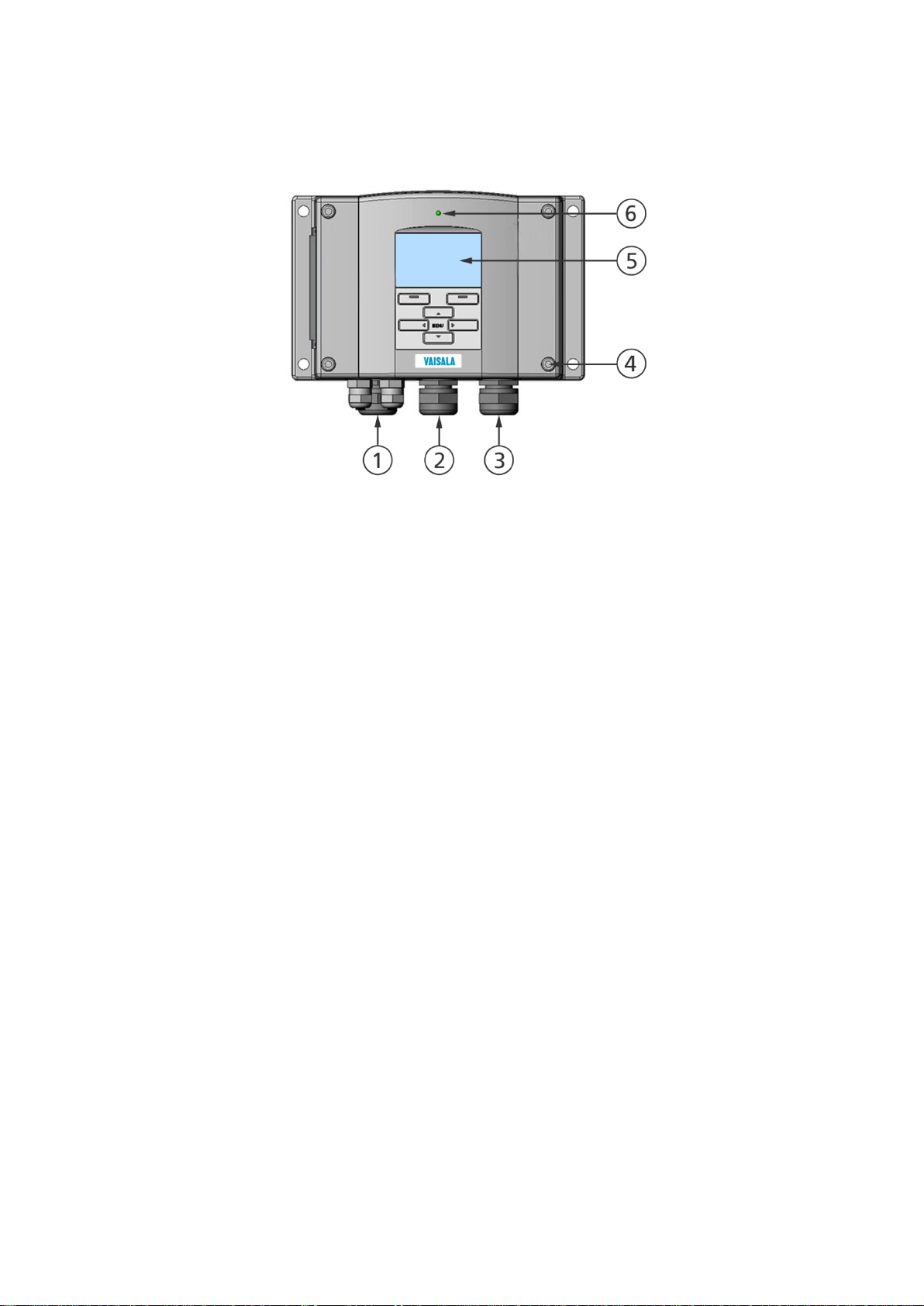
The following numbers refer to Figure 1 above:
1 = Signal + powering cable gland
2 = Cable gland for optional module, or WLAN antenna
connector
3 = Cable gland for optional module or AC mains cable
4 = Cover screw (4 pcs)
5 = Display with keypad (optional)
6 = Cover LED
Structure of the Transmitter
1104-001
Figure 1 Transmitter Body
VAISALA ________________________________________________________________________ 21
Page 24
User's Guide _______________________________________________________________________
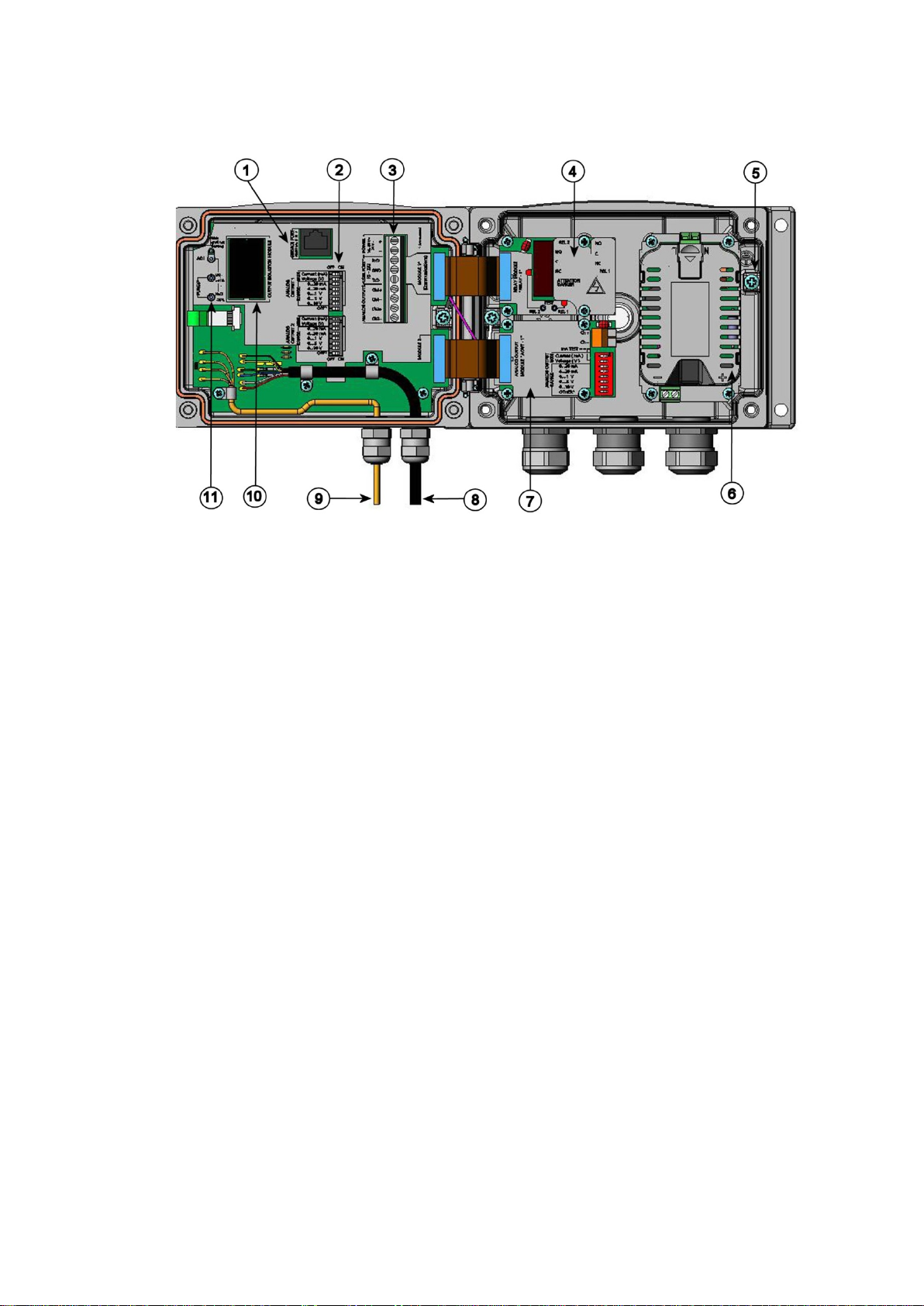
The following numbers refer to Figure 2 above:
1 = Service port (RS-232)
2 = DIP switches for analog output settings
3 = Power supply and signal wiring screw terminals
4 = Relay, data logger, RS-422/485, LAN, or WLAN module
(optional)
5 = Grounding connector
6 = Power supply module (optional)
7 = Relay, data logger, or analog output module (optional)
8 = Humidity probe cable
9 = Temperature probe cable (optional)
10 = Galvanic isolation module (optional)
11 = Adjustment buttons (chemical purge buttons) with indicator
LED
0508-010
Figure 2 Inside the Transmitter
22 ___________________________________________________________________ M210566EN-K
Page 25

Chapter 2 ___________________________________________________________ Product Overview
Probe Options
The HMT331 is intended for demanding wall-mounted applications. The
standard version has a fixed probe.
1102-025
Figure 3 HMT331 Fixed Pro be
The HMT331 short cable probe is a special version for use with the
WLAN module and when LAN module and power supply module are
simultaneously installed. It has the HMT333 probe on a short cable
(21 cm), and a mounting plate with a probe holder.
1102-024
Figure 4 HMT331 Short Cable Probe
VAISALA ________________________________________________________________________ 23
Page 26
User's Guide _______________________________________________________________________
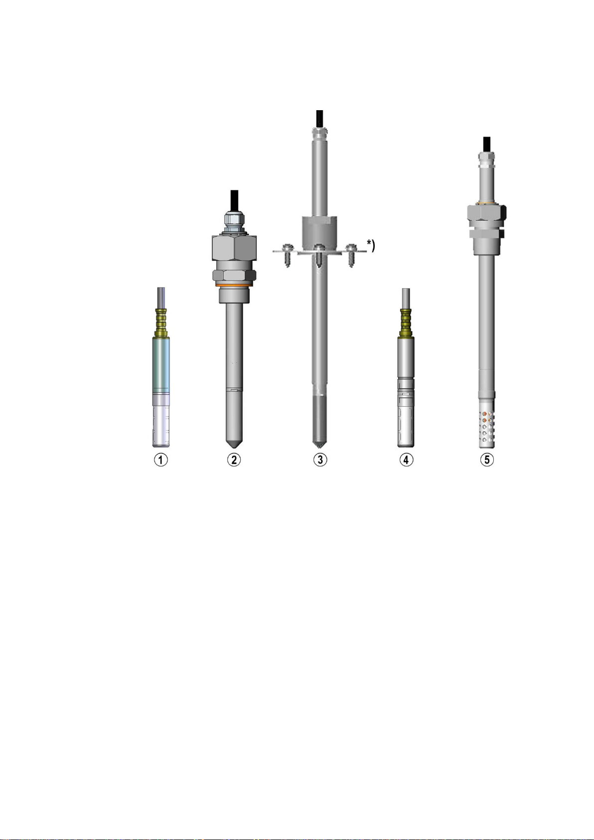
The following numbers refer to Figure 5:
1 = HMT333 for ducts and tight spaces
2 = HMT334 for high pressure and vacuum applications
(up to 100 bars)
3 = HMT335 for high temperatures (up to 180 ºC, vapor tight)
*) Flange available as an opti on
4 = HMT337 for high humidity applications
(optional warmed probe)
5 = HMT338 for pressurized pipelines (up to 40 bar)
Figure 5 Probe Options
For probe cable lengths, see Table 37 on page 175.
0911-066
24 ___________________________________________________________________ M210566EN-K
Page 27

Chapter 2 ___________________________________________________________ Product Overview
Warmed Probe HMT337
Temperature difference between the probe and external environment can
cause a risk of condensation on the sensor. A wet probe cannot observe
the actual humidity in the ambient air. If the condensed water is
contaminated, the life span of the probe may shorten and calibration may
change.
HMT337 probe shall be used in applications where condensation can
occur due to high humidity and rapid humidity changes. The warmed
probe is heated continuously so that its temperature is always higher than
in environment. This prevents condensation on the probe. The power
consumption of the warmed probe is slightly higher than other probes.
Filter Options
There are several filter types for HMT330. All filters are 12 mm in
diameter with a female thread, and are compatible with all HMT330
probe models. The filters recommended for a probe type can be selected
on the corresponding HMT330 order form.
Fore more information, see section Spare Parts and Accessories on page
178
Catalytic VHP Filter
Vaporized hydrogen peroxide (VHP) is a gaseous form of hydrogen
peroxide that is commonly used in decontamination and sterilization.
Hydrogen peroxide has relatively low saturation pressure which increases
the possibility of saturation when used in humid conditions. When
saturation conditions occur, liquid hydrogen peroxide will form on
surfaces in the decontaminated space.
Vaisala HUMICAP® sensor is compatible with direct VHP exposure
even at high concentrations and hundreds of VHP cycles up to saturation.
The long term performance is very good at concentrations higher than
typically used for sterilization. However, for the applications where full
saturation is possible, Vaisala recommends using the catalytic VHP filter
to protect the sensor and extend the calibration interval.
The catalytic filter is based on a generally known method where the H2O2
is split to H2O and O2. This reaction is produced by the catalyst layer that
has been applied to the filter. As the filter prevents the VHP from
reaching the humidity sensor, the sensor responds to humidity only. The
catalytic filter affects the reading approximately +1 %RH at 300 pmm
VHP, or +3 %RH at 900 ppm VHP (at 23 °C / 73.4 °F).
VAISALA ________________________________________________________________________ 25
Page 28

User's Guide _______________________________________________________________________
This page intentionally left blank.
26 ___________________________________________________________________ M210566EN-K
Page 29
Chapter 3 ________________________________________________________________ Installation
CHAPTER 3
INSTALLATION
This chapter provides you with information that is intended to help you
install the product.
Mounting the Housing
The housing can be mounted either without the mounting plate or with
optional mounting plates.
Standard Mounting witho ut Mount ing Plate
Mount the housing by attaching the transmitter to a wall with 4 screws,
for example, M6 (not provided).
0804-066
Figure 6 Standard Mounting
VAISALA ________________________________________________________________________ 27
Page 30
User's Guide _______________________________________________________________________
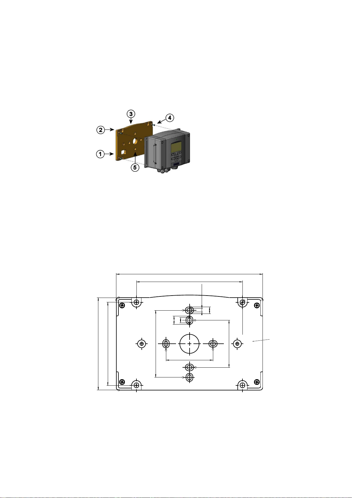
The following numbers refer to Figure 7 above:
1 = Plastic mounting plate
2 = Mount the plate to wall with 4 screws M6 (not provided)
3 = Arched side up
4 = Attach the HMT330 to the mounting plate with 4 fixing
screws M3 (provided)
5 = Holes for wall/junction box mounting
183 (7.20)
133 (5.24)
116 (4.57)
104 (4.09)
84 (3.30)
59 (2.32)
59 (2.32)
Ø6.2 (0.24)
4.5 (0.18)
10.5 (0.41)
6.5 (0.26)
8.5 (0.33)
Thickness
9.5 (0.37)
Wall Mounting with Wall Mounting Kit
When mounting with wall mounting kit the mounting plate (Vaisala
order code 214829) can be installed directly on wall or onto a standard
wall box (also US junction box). When wiring through back wall, remove
the plastic plug from the wiring hole in the transmitter before mounting.
0503-004
Figure 7 Mounting with Wall Mounting Kit
Figure 8 Dimensions of the Plastic Mounting Plate (mm/inch)
28 ___________________________________________________________________ M210566EN-K
0804-065
Page 31

Chapter 3 ________________________________________________________________ Installation
The HMT331 short cable probe is designed to be wall mounted with the
probe holder plate (Vaisala order code 226252). The probe holder plate is
similar to the standard mounting plate, except for the probe holder at the
bottom.
0911-061
Figure 9 Dimensions of the Probe Holder Plate (mm/inch)
VAISALA ________________________________________________________________________ 29
Page 32

User's Guide _______________________________________________________________________
The following numbers refer to Figure 11 above:
1 = Fixing brackets (2 pcs) M8 (provided) for 30 ... 102 mm poles
2 = Mounting nuts M8 (4 pcs)
Mounting with DIN Rail Installation Kit
DIN rail installation kit includes a wall mounting kit, 2 clip-fasteners and
2 screws M4 × 10 DIN 7985 (Vaisala order code: 215094).
1. Attach two spring holders to the plastic mounting plate by using the
screws provided in the installation kit.
2. Attach the HMT330 to the plastic mounting plate with 4 screws
(provided).
3. Press the transmitter onto the DIN rail so that the clip-fasteners
snap into the rail.
0503-002
Figure 10 Mounting with the DIN Rail Installation Kit
Pole Installation with Installation Kit for Pole or Pipeline
Installation kit for pole or pipeline (Vaisala order code: 215108) includes
the metal mounting plate and 4 mounting nuts for pole mounting. When
mounting, the arrow in the metal mounting plate must point upward; see
Figure 13 on page 31.
0503-006
Figure 11 Vertical Pole
30 ___________________________________________________________________ M210566EN-K
Page 33

Chapter 3 ________________________________________________________________ Installation
The following number refers to Figure 12 above:
1 = Mounting nuts M8 (4 pcs)
The following numbers refer to Figure 13 above:
1 = Mount the plate to wall with 4 screws M8 (not provided)
2 = Attach the HMT330 to the mounting plate with 4 fixing
screws M6 (provided)
3 = Note the position of the arrow when mounting. This side
must be up when mounting.
0503-007
Figure 12 Horizontal Pole
Metal mounting plate is included in rain shield with installation kit and
installation kit for pole or pipeline.
0503-041
Figure 13 Mounting with Metal Wall Mounting Plate
VAISALA ________________________________________________________________________ 31
Page 34

User's Guide _______________________________________________________________________
The following numbers refer to Figure 15 above:
1 = Fasten the rain shield with the installation kit (Vaisala order
code: 215109) to the metal mounting plate with 2 (M6) mounting
screws (provided)
2 = Fasten the mounting plate with rain shield with installation kit to
the wall or to the pole (see pole installation)
3 = Fasten the transmitter to the mounting plate with 4 fixing screws
(provided)
0509-151
Figure 14 Dimensions of the Metal Mounting Plate (mm/inch)
Mounting Rain Shield with Installa tion Kit
The rain shield is highly recommended for outdoor installations,
especially for transmitters with the display/keypad option.
0503-008
Figure 15 Mounting the Rain Shield with the Installation Kit
32 ___________________________________________________________________ M210566EN-K
Page 35

Chapter 3 ________________________________________________________________ Installation
The following numbers refer to Figure 16 above:
1 = Panel (not included)
2 = Panel mounting frame
Panel Mounting Frame
To enable a neat and dirt free embedded installation of the transmitter, a
panel mounting frame is available as an option (Vaisala order code:
216038). The frame is a thin, flexible plastic frame for the transmitter,
with adhesive tape on one side.
The frame is used to hide any rough edges of the installation hole, and
provide a more finished look. Note that the panel mounting frame is not
intended to bear the weight of the transmitter, and does not include any
mounting supports.
Use the panel mounting frame as follows:
1. Use the frame as a template to mark the required size for the
installation hole in the panel.
2. Cut the hole in the panel.
3. Mount the transmitter through the panel with suitable supports.
4. Remove the paper protecting the adhesive tape on the frame, and
attach the frame around the transmitter. Refer to Figure 16 below.
0704-002
Figure 16 Panel Mounting Frame
VAISALA ________________________________________________________________________ 33
Page 36

User's Guide _______________________________________________________________________
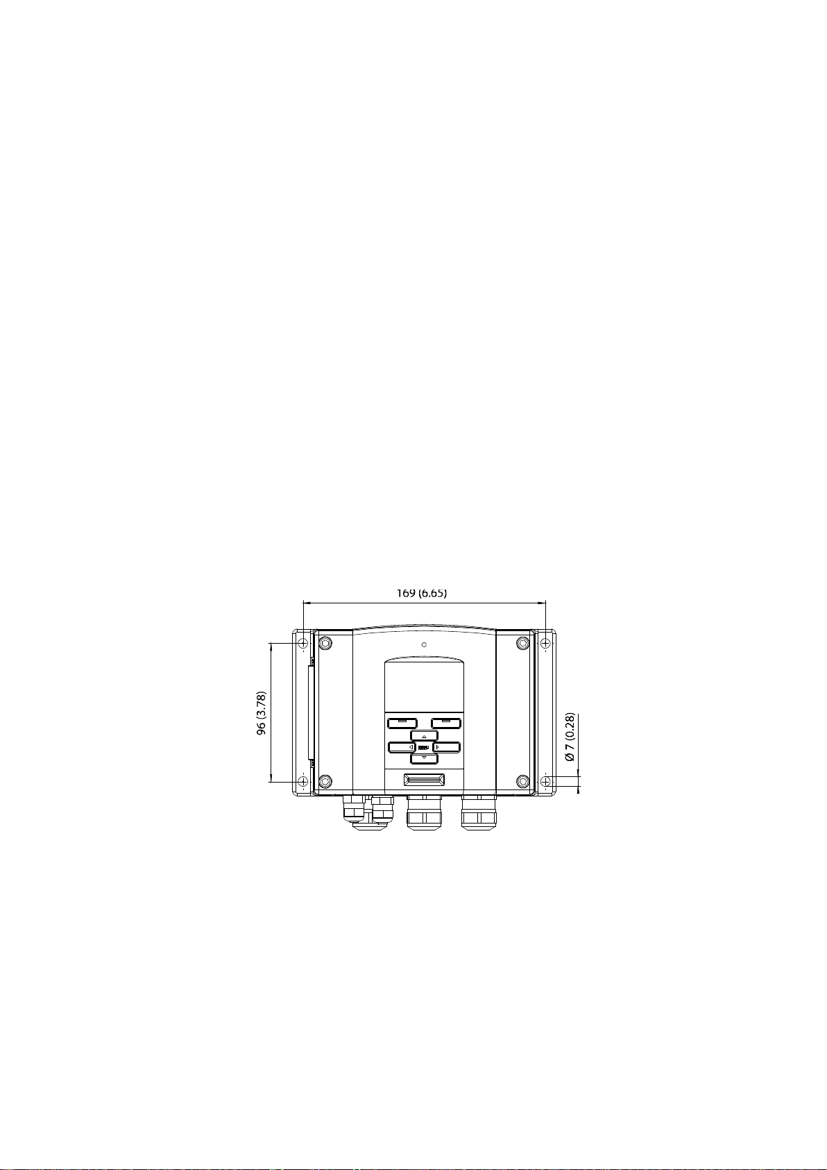
The following numbers refer to Figure 18 above:
1 = Cable for signal/powering Ø8 ... 11 mm
2 = Cable for optional module Ø8 ... 11 mm
3 = Cable for optional power supply module Ø8 ... 11 mm
0804-083
Figure 17 Panel Mounting Dimensions (mm/inch)
Wiring
Cable Bushings
A single electrical cable with screen and three to ten wires is
recommended for power and analog/serial connections. The cable
diameter should be 8 ... 11 mm. The number of cable bushings depends
on the transmitter options. See the following recommendations for the
cable bushings:
0503-010
Figure 18 Cable Bushings
34 ___________________________________________________________________ M210566EN-K
Page 37

Chapter 3 ________________________________________________________________ Installation
When there is high electric noise
electric motor) in the operating environment it is recommended to use
shielded cable or take care that the signal cables are separated from other
cables.
NOTE
level (for example, near a powerful
Grounding the Cables
Ground the screen of the electrical cable properly to achieve the best
possible EMC performance.
Figure 19 Grounding the Screen of Electrical Cable
VAISALA ________________________________________________________________________ 35
0605-027
Page 38

User's Guide _______________________________________________________________________
Refer to Figure 19 on page 35 when performing the procedure below.
1. Cut back outer sheath to desired length.
2. Cut back screen braiding or screen foil to dimension X.
3. Push the domed cap nut (item 1) and the seal insert with contact
socket of the gland (item 2+3) onto the cable as shown in the
diagram.
4. Bend over the screen braiding or screen foil by about 90º
(item 4).
5. Push the seal insert with the contact socket of the gland
(item 2+3) up to the screen braiding or screen foil.
6. Mount the lower part (item 5) on the housing.
7. Push the seal with the contact socket of the gland (item 2+3)
into the lower part (item 5).
8. Attach the domed cap nut (item 1) onto the lower part (item 5).
Grounding the Transmitter Housing
In case you need to ground the transmitter housing, the grounding
connector is found inside the housing; see Figure 2 on page 22. Note that
the probe is connected to the same potential as the housing. Make sure
that different groundings are made to the same potential. Otherwise
harmful ground currents may be generated.
If it is needed to have galvanic isolation of the power supply line from
the output signals, the HMT330 can be ordered with an optional galvanic
isolation module. This module prevents harmful grounding loops.
36 ___________________________________________________________________ M210566EN-K
Page 39

Chapter 3 ________________________________________________________________ Installation
The following numbers refer to Figure 20 above:
1 = Power supply terminals 10 ... 35 VDC, 24 VAC
2 = User port (RS-232 terminals)
3 = Analog signal terminals
Make sure that you connect only de
Signal and Power Supply Wiring
When connecting the transmitter with 8-pin connector, see section
8-Pin Connector on page 66. When wiring the power supply module, see
section Power Supply Module on page 49.
0506-028
WARNING
Figure 20 Screw Terminal Block on Motherboard
-energized wires.
1. Unfasten the four cover screws and open the transmitter cover.
2. Insert the power supply wires and signal wires through the cable
bushing in the bottom of the transmitter; see the grounding
instructions in the previous sections.
3. Connect the analog output cables to terminals: Ch1+, Ch1-, Ch2+,
Ch2-. Connect the RS-232 user port cables to terminals RxD, GND
and TxD. For more information about the RS-232 connection refer
to section Serial Line Communication on page 79.
4. When wiring the optional modules, see the corresponding section
for instructions:
- RS-422/485 Interface on page 57
- Relays on page 56
- Third Analog Output on page 54
- LAN Interfac e on page 62
- WLAN Interface on page 63
VAISALA ________________________________________________________________________ 37
Page 40

User's Guide _______________________________________________________________________
24
To prevent fire and/or damage, if either 24
connected to a "
must connect the same wire on the "
5. Connect the power supply wires to the connectors: POWER
10 ... 35V+ 24V~ (+) and (-) terminals. If you are using 24 VAC
power supply, see the note below before connecting the supply
wires.
6. Turn on the power. The indicator LED on the cover is lit
continuously during normal operation.
7. Close the cover and fasten the cover screws. The transmitter is
ready for use.
Connections to a 24 VAC Power Supply
Separate floating supply for each transmitter is recommended (see the
upper part of Figure 21 on page 39). If you have to connect several
transmitters or other instruments to one AC supply, the phase (~) must
always be connected to the (+) connector of each transmitter (see the
lower part of Figure 21).
CAUTION
VAC POWER SUPPLY USE
VAC wire is grounded or
-", "0", or "GND" terminal of any other device, you
-" terminal also on this instrument.
38 ___________________________________________________________________ M210566EN-K
Page 41

Chapter 3 ________________________________________________________________ Installation
Figure 21 Connections to 24 VAC Power Supply
0703-041
VAISALA ________________________________________________________________________ 39
Page 42

User's Guide _______________________________________________________________________
Probe Mounting
In humidity measurement and especially in calibration it is essential that
temperature of the probe and measuring environment is the same. Even a
small difference in temperature between the environment and the probe
causes an error. As the curve below shows, if the temperature is +20 °C
and the relative humidity 100 %RH, a difference of ±1 °C between the
environment and the probe causes an error of ±6 %RH.
The graph below illustrates the measurement error at 100 %RH when the
difference between the ambient and sensor temperature is 1 °C.
Figure 22 Measurement Error at 100 %RH
0507-023
40 ___________________________________________________________________ M210566EN-K
Page 43

Chapter 3 ________________________________________________________________ Installation
The following numbers refer to Figure 23 above:
1 = To be sealed
2 = To be insulated
3 = Insulate the cable
4 = Let the cable hang loosely. This prevents condensed water
running to the probe along the cable.
General Instruct ions for Probes with a Cable
Mount the probes with a cable horizontally; this way, any water
condensing on the tube cannot flow onto the sensor.
0507-024
Figure 23 Horizontal Mounting of Probe
VAISALA ________________________________________________________________________ 41
Page 44

User's Guide _______________________________________________________________________
The following numbers refer to Figure 24 above:
1 = To be sealed
2 = Insulate the cable
3 = To be insulated
4 = Let the cable hang loosely. This prevents condensed water
running to the sensor along the cable.
Please do not attach a heated probe (HMT337) to metal structures to
avoid condensation problems caused by heat conduction along the metal.
When there is no alternative but to install the probe in the process
vertically, the point of entry must be carefully insulated. The cable must
also be allowed to hang loosely as this prevents any condensed water
from running onto the probe along the cable.
0507-022
NOTE
Figure 24 Vertical Mounting of Probe
If the process temperature is much higher than that of the environment,
the whole probe and preferably plenty of cable must be inside the
process. This prevents measuring inaccuracy caused by heat conduction
along the cable.
When mounted on the side of a duct or channel, the probe must be
inserted from the side of the duct. If this is not possible and the probe
must be inserted from the top, the point of entry must be carefully
insulated.
For Vaisala probe installation kits and some installation examples, see
Appendix A on page 185.
42 ___________________________________________________________________ M210566EN-K
Page 45

Chapter 3 ________________________________________________________________ Installation
HMT333 for Ducts an d Tight Spaces
The HMT333 is a small size (ø = 12mm) general-purpose probe suitable
for ducts and channels with the installation kit available from Vaisala.
The HMT333 provides for two measuring range options. The first probe
version is equipped with a flexible cable and can be used when
measuring in environments up to 80 ºC. The second version is suitable
for measuring in environments up to 120 ºC.
See Appendix A on page 185 for the following probe installation kits for
HMT333 and installation examples.
- Duct mounting kit
- Cable gland
HMT334 for High Pressure and Vacuum Applications
The HMT334 probe is for the dewpoint measurements in pressurized
rooms and industrial processes. The probe is provided with a nut, a fitting
screw and a sealing washer. Keep the fitting screw and the nut in place
on the body of the probe during handling to prevent damage to the highly
polished surface of the probe. Follow the instructions below to achieve a
leak-tight assembly:
1. Remove the fitting screw from the nut and the probe.
2. Attach the fitting screw to the chamber wall with a sealing washer.
Tighten the fitting screw into the threaded sleeve with a torque
wrench. The tightening torque is 150 ± 10 Nm (110 ± 7 ft-lbs).
3. Insert the body of the probe into the fitting screw and attach the nut
manually to the fitting screw so that the connection feels tight.
4. Mark both the fitting screw and the nut hex.
VAISALA ________________________________________________________________________ 43
Page 46

User's Guide _______________________________________________________________________
The following numbers refer to Figure 25 above:
1 = Tightening cone
2 = Nut
3 = Fitting screw, M22x1.5 or NPT 1/2"
4 = Sealing washer
5 = Probe; Ø12 mm
0506-029
Figure 25 HMT344 Probe
NOTE
5. Tighten the nut a further 30º (1/12) turn or if you have a torque
wrench tighten it with a torque of 80 ± 10 Nm (60 ± 7 ft-lbs).
0503-034
Figure 26 Tightening the Nut
When re-tightening the nut after detachment the nut must be tightened
without increased effort.
6. Clean and grease the tightening cone of the fitting screw after every
tenth detachment. Change the sealing washer every time the fitting
screw is detached. Use high-vacuum gr ease (fo r e x am pl e Dow
Corning) or similar grease.
44 ___________________________________________________________________ M210566EN-K
Page 47

Chapter 3 ________________________________________________________________ Installation
The following numbers refer to Figure 27 above:
1 = Fitting screw
2 = Sealing washer
3 = Tightening cone
4 = Clean cotton stick
In pressurized processes it is essential to tighten the supporting nuts and
screws very
pressure.
When installed in a process with a pressure differing from normal
atmospheric pressure, please enter the pressure value of the process
(in
option, using the serial line (see section
or using the
0503-033
Figure 27 Cleaning of Tightening Cone
CAUTION
NOTE
carefully to prevent loosening of the probe by the action of
hPa or mbar) into the transmitter memory using the display/keypad
PRES and XPRES on page 104),
Modbus protocol (see Configuration Registers on page 203).
HMT335 for High Temperatures
HMT335 is installed similarly as the HMT333 probe but without the
supporting bar. Refer to Appendix A on page 185 for more information
on the duct installation kit for HMT335.
To avoid incorrect humidity readings, the temperature differences
between inside and outside of the duct must not be remarkable.
VAISALA ________________________________________________________________________ 45
Page 48

User's Guide _______________________________________________________________________
HMT337 for High Humidity Applications
The HMT337 is designed for environments where relative humidity is
very high, near saturation. The warmed probe prevents the saturation of
the sensor. An additional temperature probe is also available.
See Appendix A on page 185 for a presentation of the following probe
installation kits for HMT337 with installation examples:
- Duct mounting kit
- Cable gland
- Pressure tight Swagelok connector
- Vaisala's Meteorological Installation Kit
The installation kits are available for both humidity and temperature
probe.
Temperature Probe (Opti ona l)
An additional temperature probe is available to measure the ambient
temperature when the HMT337 (with probe warming) is used. The
additional temperature probe allows you to measure other humidity
quantities apart from dewpoint and mixing ratio. The temperature probe
must be connected to the transmitter at the factory. Do not cut and reconnect the cable yourself.
You must install the additional temperature probe in the same
measurement environment as the HMT337 probe. Make sure that heat
does not transfer from the warmed probe to the temperature probe. For an
example installation, refer to section Example of Installation Through
Roof on page 191.
HMT338 for Pressuri zed Pipelines
Due to the sliding fit the HMT338 is easy to install into and remove from
the pressurized process. The probe is especially suitable for the
measurements in pipelines. See section Ball Valve Installation Kit for
HMT338 on page 192.
46 ___________________________________________________________________ M210566EN-K
Page 49

Chapter 3 ________________________________________________________________ Installation
The following numbers refer to Figure 28 above:
1 = Clasp nut, 24 mm hex nut
2 = Fitting body, 27 mm hex head
Probe type
Probe Dimension
Adjustment Range
Standard
178 mm
120 mm
Optional
400 mm
340 mm
0508-077
Figure 28 HMT338 Probe
The following two fitting body options are available:
- Fitting Body ISO1/2 solid structure
- Fitting Body NPT1/2 solid structure
Table 5 HMT338 Probe Dimensions
Figure 29 Sealing of Fitting Body into Process
VAISALA ________________________________________________________________________ 47
0507-025
Page 50

User's Guide _______________________________________________________________________
The following numbers refer to Figure 30 above:
1 = Probe
2 = Clasp nut
3 = Fitting screw
4 = Pen
Take care not to damage the probe body. A damaged body makes the
probe less tight and may prevent it from going through the clasp nut.
In pressurized processes it is essential to tighten the supporting nuts and
screws very carefully to
pressure.
Take care not to over tighten the clasp nut to avoid difficulties when
opening it.
Tightening the Clasp Nut
1. Adjust the probe to a suitable depth according to the type of
installation.
2. Tighten the clasp nut first manually.
3. Mark the fitting screw and the clasp nut.
4. Tighten the nut a further 50 -60º (ca. 1/6 turn) with a wrench. If
you have suitable torque wrench, tighten the nut to max 45 ± 5 Nm
(33 ± 4 ft-lbs).
CAUTION
CAUTION
NOTE
0505-276
Figure 30 Tightening the Clasp Nut
prevent loosening of the probe by the action of
48 ___________________________________________________________________ M210566EN-K
Page 51

Chapter 3 ________________________________________________________________ Installation
When installed in a process with a pressure differing from normal
atmospheric pressure, please enter the pressure value of the process (in
hPa or mbar) into the transmitter memory
the display/keypad option, using
XPRES
Registers
The following numbers refer to Figure 31 above:
1 = Connect AC (mains) voltage wires to these terminals
2 = Grounding terminal
3 = In case the module is not installed in the factory: Connect
wires from these terminals to the POWER 10
terminals of the motherboard.
4 = + 5 =
-
NOTE
. You can enter the value using
the serial line (see section PRES and
on page 104), or using the Modbus protocol (see Configuration
on page 203).
Optional Modules
Power Supply Module
The AC (mains) power connection may be connected to the power supply
module only by an authorized electrician. A readily accessible disconnect
device shall be incorporated in the fixed wiring.
0506-027
Figure 31 Power Supply Module
VAISALA ________________________________________________________________________ 49
... 35V 24V
Page 52

User's Guide _______________________________________________________________________
Do not detach the power supply module from the transmitter when the
power is on.
Do not connect the mains power to power supply module when it is not
ins
Always connect the protective ground terminal.
Installation
1. Disconnect the power and open the transmitter cover.
2. Remove the protective plug from the cable gland and thread the
wires. In case the power supply module is installed in the factory,
continue with the step 5.
3. Attach the power module to the bottom of the housing with four
screws. See the position in Figure 2 on page 22.
4. Connect the wires from the terminals of the power supply module
marked with + and - to the terminals POWER 10 ... 35 V 24V on
the motherboard of the transmitter.
5. Connect the AC mains voltage wires to the power supply module
terminals marked with N and L.
6. Attach the grounding wire to the grounding terminal on the righthand side of the transmitter.
7. Connect the power. The LED on the cover of the transmitter is lit
continuously during normal operation.
WARNING
WARNING
WARNING
talled in the transmitter.
50 ___________________________________________________________________ M210566EN-K
Page 53

Chapter 3 ________________________________________________________________ Installation
Warnings
Dieses Produkt entspricht der Niederspannung srichtlinie (2006/95/EWG).
- Das Netzmodul darf nur von einem dazu befugten Elektriker angeschlossen werden.
- Trennen Sie das Netzmodul nicht vom Messwertgeber , wenn der Strom eingeschaltet ist.
- Verbinden Sie das Netzmodul nur mit der Spannungsquelle, wenn es im Messwertgeber
HMT330 montiert ist.
- Das Erdungskabel muss zum Schutz immer angeschlo s sen sein.
Ce produit est conforme à la Directive relative à la Basse Tension (2006/95/EEC).
- Seul un électricien compétent est habilité à raccorder le module d’alimentation au secteur.
- Ne pas détacher le module d’alimentation du transmetteur lorsqu’il est en service.
- Ne pas raccorder le secteur au module d’alimentatio n lorsque celui-ci n’est pas installé dans le
transmetteur HMT330.
- Toujours raccorder un bornier de protection à la terre.
Tämä tuote on pienjännitedirektiivin (2006/95/EEC) mukainen.
- Vaihtovirtaliitännän saa kytkeä tehonsyöttömoduuliin ainoastaan valtuutettu sähköasentaja
- Älä irrota tehonsyöttömoduulia lähettimestä, kun virta on kytkettynä.
- Älä kytke verkkovirtaa tehonsyöttömoduuliin, jos kyseistä moduulia ei ole asennettu
HMT330 lähettimeen.
- Kytke aina maadoitusliittimet.
Denna produkt uppfyller kraven i direktivet om lågspänning (2006/95/EEC).
- Nätanslutningen (växelströmsanslutningen) får bara anslutas till strömförsörjningsmodulen av
en behörig elektriker.
- Ta inte loss strömförsörjningsmodulen från mätaren när strömmen är på.
- Anslut inte strömförsörjningsmodulen till nätet när den inte är installerad i HMT330-mätaren
- Anslut alltid en skyddande jordningsplint.
Questo prodotto è conforme alla Direttiva sul basso voltaggio (2006/95/CEE).
- La conduttura elettrica può essere coll egat a al modulo di alimentazione elettrica soltanto da
un elettricista au to r izzato.
- Non staccare l’al imentazione elettrica dal trasmettitore quando è acceso.
- Non collegare la corrente elettrica al modulo di alimentazione elet trica se non è installato nel
trasmettitore HMT330.
- Collegare sempre il morsetto protettivo a terra!
VAISALA ________________________________________________________________________ 51
Page 54

User's Guide _______________________________________________________________________
Dette produkt er i overensstemmelse med direktivet om lavspænding
(2006/95/EØS).
- Netstrømskoblingen til må kun tilsluttes strømforsyningsmodulet af en autoriseret elinstallatør
- Strømforsyningsmodulet må ikke løsgøres fra senderen, mens spændingen er sluttet til.
- Slut ikke netspændingen til strømforsyningsmodulet, når det ikke er installeret i HMT330-
senderen
- Forbind altid den beskyttende jordklemme!
Dit product voldoet aan de eisen van de richtlijn 2006/95/EEG
(Laagspanningsrichtlijn).
- De stroom kan aan de stroomtoevoer module aangesloten worden alleen door een bevoegde
monteur.
- Het is niet toegestaan de stroomtoevoer module van de transmitter los te koppelen wanneer de
stroom aan is.
- Het is niet toegestaan de stroom aan de stroomtoevoer mod ule aan te sluiten al s deze niet in
een HMT330-transmitter is gemonteerd.
- Altijd beschermend aard contact aansluiten!
Este producto cumple con la directiva de bajo voltaje (2006/95/EEC).
- La conexión de la alimentación principal al módulo de alimentación sólo puede realizarla un
electricista autorizado.
- No desenchufe el módulo de alimentación del transmisor cuando esté encendido.
- No conecte la alimentación principal al módulo de alimentación cuando no est é instalado en
el transmisor HMT330.
- Conecte siempre el terminal de protección de conexión a tierra.
See toode vastab madalpinge direktiivile (2006/95/EEC).
- Voolukaabli võib vooluallika mooduli külge ühendada ainult volitatud elektrik.
- Ärge ühendage vooluallika moodulit saatja küljest lahti, kui vool on sisse lülitatud.
- Ärge ühendage voolukaablit vooluallika mooduli külge, kui seda pole HMT330-tüüpi
saatjasse paigaldatud.
- Ühendage alati kaitsev maandusklemm!
Ez a termék megfelel a Kisfeszültségű villamos termékek irányelvnek
(2006/95/EGK).
- A hálózati feszültséget csak feljogosított elektrotechnikus csatlakoztathatja a
tápegységmodulra.
- A bekapcsolt távadóról ne csatolja le a tápegységmodult.
- Ne csatlakoztassa a háló zati feszültséget a tápegységmodulhoz, ha az nincs beépítve a
HMT330 távadóba.
- Feltétlenül csatlakoztasson földelő védőkapcsot!
52 ___________________________________________________________________ M210566EN-K
Page 55

Chapter 3 ________________________________________________________________ Installation
Šis produktas atitinka direktyvą dėl žemos įtampos prietaisų (2006/95/EB).
- Elektros tinklą su energijos tiekimo moduliu sujungti gali tik įgaliotas elektrikas.
- Niekada neišimkite energijos tiekimo modulio iš siųstuvo, kai maitinimas yra įjungtas.
- Jei energijos tiekimo modulis nėra įmontuotas HMT330 siųstuve, nejunkite jo į elektros
tinklą.
- Visada prijunkite prie apsauginės įžeminimo jungties!
Šis produkts atbilst Zemsprieguma direktīvai (2006/95/EEC).
- Strāvas pieslēgumu var pieslēgt pie barošanas avota moduļa tikai autorizēts elektriķis.
- Neatvienot barošanas avota moduli no raidītāja, kad pieslēgta strāva.
- Nepievienot strāvu barošanas avota modulim, ja tas nav uzstādēts HMT330 raidītājā
- Vienmēr pievienot aizsargājošu iezemētu terminālu !
Ten produkt spełnia wymogi Dyrektywy niskonapięciowej (2006/95/EEC).
- Napięcie zasilające powinno zostać podłączone do modułu zasilacza tylko przez
wykwalifiko w a nego elektryka .
- Nie wolno odłączać modułu zasilacza od nadajnika, kiedy zasilanie jest włączone.
- Nie wolno podłączać napięcia zasilającego do modułu zasilacza, kiedy nie jest on
zamontowany w nadajniku HMT330.
- Zawsze należy podłączać zabezpieczający zacisk uziemiający!
Tento výrobek vyhovuje Směrnici pro nízké napětí (2006/95/EEC).
- Připojení síťového napájení k napájecímu modulu smí provádět pouze oprávněný elektrikář.
- Neodpojujte napájecí modul od snímače při zapnutém napájení.
- Nepřipojujte síťové napájení k napájecímu modulu, pokud není instalován ve snímači
HMT330.
- Vždy zapojte ochrannou zemnící svorku!
VAISALA ________________________________________________________________________ 53
Page 56

User's Guide _______________________________________________________________________
Galvanic
supply module.
incompatible to be installed at the same time. If both modules are
installed, there is no room to close the transmitter cover completely.
The following number refers to Figure 32 above:
1 = Galvanic isolation module
The following numbers refer to Figure 33 above:
1 = Flat cable pins
2 = Screw terminals for signal line
3 = DIP switches to select the output mode and range
Galvanic Isolation of the Power Supply
If galvanic isolation of the power supply line from the output signals is
needed, HMT330 can be ordered with optional galvanic isolation
module. This module prevents harmful grounding loops.
NOTE
isolation module is not needed when using the AC power
Note also that these two modules are physically
0506-030
Figure 32 Galvanic Isolation Module
Third Analog Output
Figure 33 Third Analog Output
54 ___________________________________________________________________ M210566EN-K
0503-030
Page 57

Chapter 3 ________________________________________________________________ Installation
Installation and Wiring
1. Disconnect the power. In case the analog output module is installed
in the factory, continue with the step 4.
2. Open the transmitter cover and fasten the analog output module to
the position for MODULE 2 with four screws. Refer to Figure 2 on
page 22.
3. Connect the flat cable between the analog output module and the
motherboard's connector for MODULE 2.
4. Take out the protective plug from the cable gland and thread the
wires.
5. Connect the wires to the screw terminals marked with Ch+ and
Ch- .
6. Select the current/voltage output by setting ON either of the
switches 1 or 2.
7. Select the range by setting ON one of the switches 3 ... 7.
NOTE
Only one of the switches 1 ... 2 can be ON at a time.
Only one of the switches 3 ... 7 can be ON at a time.
0508-029
Figure 34 Third Analog Output Selection
8. Connect the power.
9. Select the quantity and scale the channel via the serial line or
display/keypad, see section Analog Output Quantities on page 121.
For testing the analog output, see section Analog Output Tests on
page 123. For fault indication setting, see section Analog Output
Fault Indication Setting on page 124.
VAISALA ________________________________________________________________________ 55
Page 58

User's Guide _______________________________________________________________________
For installations in the USA: If your transmitter has both the relay
module and a LAN or WLAN module, the maximum voltage you are
allowed to con
NO
Normally open
C Common relay
NC Normally closed
Relay NOT activated:
C and NC outputs are closed, NO is open
Relay IS activated:
C and NO outputs are closed, NC is open.
For instructions on how to operate the relay (for example,
quantity for the relay output and set
Operation of Relays
Relays
HMT330 can be equipped with one or two configurable relay modules.
Each module contains two configurable relays. See the contact ratings in
section Technical Specifications of Optional Modules on page 176.
Installation and Wiring
1. Disconnect the power and open the transmitter cover. In case the
relay-module is installed in the factory, continue with step 5.
2. Attach the relay module to the bottom of the housing with four
screws. See the position in Figure 2 on page 22.
3. When the mains power is in use attach the grounding wire to the
grounding terminal.
4. Connect the flat cable between the relay module and the
MODULE 1 or MODULE 2 pins of the motherboard.
5. Take out the protective plug from the cable gland and thread the
relay wires.
CAUTION
6. Connect the wires to the screw terminals: NO, C, and NC. Refer to
section Selecting the Activation State of the Relay below.
nect to the relay module is 50 V.
7. Connect the power and close the cover.
Selecting the Activation State of the Relay
The middlemost C terminal and either one of the terminals NO/NC must
be connected. The polarity can be freely selected.
NOTE
ting the relay setpoints), see section
on page 125.
56 ___________________________________________________________________ M210566EN-K
selecting
Page 59

Chapter 3 ________________________________________________________________ Installation
The following numbers refer to Figure 35 above:
1 = Indication led for the relay 1 or 3
2 = Relay test buttons
3 = Flat cable pins
4 = Indication led for relay 2 or 4
The relay module may contain dangerous voltages even if the
transmitter power has been disconnected. Before opening the transmitter
you must switch off
the relay terminals.
Do not connect the main
transmitter.
RS
connected when RS
normally.
0503-037
Figure 35 Relay Module
WARNING
WARNING
both the transmitter and the voltage connected to
s power to relay unit without grounding the
RS-422/485 Interf ace
The RS-422/485 interface enables communication between an RS-485
network and the HMT330 transmitter. The RS-485 interface is isolated
and offers a maximum communications rate of 115 200 bits/s. (For
maximum bus length of 1 km, use bit rate 19200 b/s or less.)
When selecting an RS-232 to RS-485 converter for the network, avoid
self-powered converters, as they do not necessarily support the needed
power consumption.
NOTE
VAISALA ________________________________________________________________________ 57
-232 User Port on HMT330 main board cannot be used and
-485 module is connected. Service port operates
Page 60

User's Guide _______________________________________________________________________
The following numbers refer to Figure 36 above:
1 = Flat cable pins
2 = Selection switches
3 = Screw terminals for wiring
The data lines on earlier versions of the
A and B instead of D1+ and D0
voltage compared to D0
When connecting the module, be prepared to swap the
wires if you have a communication problem.
1
2
3
1102-023
Figure 36 RS-422/485 Module
NOTE
RS-422/485 module are marked
-. When the line is idle, D1+ has positive
-.
D1+ and D0-
Installation and Wiring
1. Disconnect the power. In case the RS-422/485-module is installed
in the factory, continue with the item 4.
2. Open the transmitter cover and attach the RS-422/485 module to
the bottom of the housing with four screws.
3. Connect the flat cable between the RS-422/485 module and the
motherboard's pins MODULE1 (Communications).
4. Pull the network wirings through the cable gland.
58 ___________________________________________________________________ M210566EN-K
Page 61

Chapter 3 ________________________________________________________________ Installation
Screw Terminal
Data Line
(2-wire RS-485)
Data Line
(4-wire RS-422/485)
1
(not connected)
Rx D0-
2
(not connected)
Rx D1+
3
Common
Common
4
D0-
Tx D0-
5
D1+
Tx D1+
If you use the internal termination of the transmitter at the end of the
RS
transmitter will block the bus operation.
5. Connect the twisted pair wires (1 or 2 pairs) to the screw terminals
as presented in Table 6 below:
Table 6 Connecting the Twisted Pair Wires to the Screw
Terminals
To avoid problems in the RS-422/485 network, the Common
terminal should be wired to the corresponding terminals of the
other devices.
6. If you use RS-422 or RS-485 to connect just one HMT330 to a
master computer, enable the internal termination of HMT330 by
switching switches 1 and 2 ON. Make sure that the master's end of
the line is also terminated (by using master's internal termination or
with a separate terminator).
NOTE
If you are connecting many transmitters to the same RS-485 bus,
make sure that switches 1 and 2 are OFF and terminate the bus with
separate terminators at both ends. This allows removing any
transmitter without blocking the bus operation.
-485 bus (instead of using separate terminators) removing that
7. Use the bus type (4-wire/2-wire) to select the selection switch 3.
In 4-wire mode RS-485 master sends data to the HMT330 through
terminals Rx D1+ and Rx D0- and receives data from HMT330
through terminals Tx D1+ and Tx D0-.
VAISALA ________________________________________________________________________ 59
Page 62

User's Guide _______________________________________________________________________
RS-485 master
Data
HMT330
Tx D1+
→
Rx D1+
Tx D0-
→
Rx D0-
Rx D1+
←
Tx D1+
Rx D0-
←
Tx D0-
Stub
Termination Termination
Termination Termination
Twisted pair
120R
120R
120R
120R
Twisted pair
Stub
Stub
Baud > 19.2K Stub < 10ft, 3m
Baud >112K Stub < 1ft, 0.3m
Rx D0Rx D1+
Common
Tx D0Tx D1+
Switch
Term off
Term off
2/4 wire on
RS422 off
Tx D0Tx D1+
Common
Rx D0Rx D1+
Switch
Term off
Term off
2/4 wire on
RS422 off
Tx D0Tx D1+
Common
Rx D0Rx D1+
RS485-1
RS485-1
Address MM
Address NN
RS485 bus master
Junction
box
Junction
box
Junction
box
Common
line
Common
line
1102-028
Figure 37 4-Wire RS-485 Bus
Table 7 4-Wire (Switch 3: On)
60 ___________________________________________________________________ M210566EN-K
Page 63

Chapter 3 ________________________________________________________________ Installation
RS-485 master
Data
HMT330
D1+
↔
D1+
D0- ↔ D0-
Termination
Termination
Junction
box
Junction
box
Junction
box
120R
D0D1+
Common
Switch
Term off
Term off
2/4 wire off
RS422 off
Stub
Stub
Stub
RS485-1
RS485-1
RS485 bus master
Twisted pair Common line
Address NN
Address MM
Common
D0D1+
Switch
Term off
Term off
2/4 wire off
RS422 off
Common
D0D1+
120R
Twisted pair Common line
Figure 38 2-Wire RS-485 Bus
Table 8 2-Wire (Switch 3: Off)
8. When operating in communication mode RS-422, set both switches
3 and 4 to ON position (4-wire wiring is required for RS-422
mode).
9. Connect the power and close the cover.
1102-027
VAISALA ________________________________________________________________________ 61
Page 64

User's Guide _______________________________________________________________________
1 =
Flat cable connector
2 =
RJ45 connector with
indicator LEDs for
link and activity
LAN Interface
The optional LAN interface enables an Ethernet connection to the
transmitter. The user can establish a virtual terminal session using a
Telnet client program such as PuTTY or by using Modbus TCP protocol.
When the LAN interface is in use, serial communication using the RS232 User Port is disabled.
The LAN interface module must be installed at the factory (when
ordering the transmitter), or by a Vaisala Service Center. Once installed,
the module is automatically used by the transmitter. The physical
connection to the network is made to the RJ45 connector on the LAN
interface module, using a standard twisted pair Ethernet cable
(10/100Base-T). Transmitters with the optional LAN interface are
delivered pre-installed with a suitable cable and cable gland.
The LAN interface can use both static and dynamic network settings. If
the interface is configured to use dynamic settings, the network where the
LAN interface is connected must have a DHCP server that provides the
settings.
CAUTION
The network configuration can be done using the optional display and
keypad, or by using the service port. For instructions, see section LAN
Communication on page 82. The LAN interface also provides a web
configuration interf ace , whi ch you can acc ess b y entering the IP address
of the LAN interface in the address field of a web browser. See section
Web Configuration for LAN and WLAN on page 89.
The LAN interface is designed to be used in trusted network
environments (trusted corporate LAN or VPN-based connection over
internet). Avoid connecting the transmitter directly to a public network
because the device can be attacked by a malicious user through the
network.
62 ___________________________________________________________________ M210566EN-K
0709-003
Figure 39 LAN Interface Module
Page 65

Chapter 3 ________________________________________________________________ Installation
1 =
Flat cable connector
2 =
Connector for antenna
cable (connected to
transmitter cover)
The WLAN interface is designed to be used in trusted network
environments (trusted corporate LAN or VPN
internet). Avoid connecting the
because the device can be attacked by a malicious user through the
network.
The default
which limits the operation to WLAN channels 1 ... 11. To enable
additional channels (12 ... 14), you can change the country setting using
the
WLAN Interface
The optional WLAN interface enables a wireless Ethernet connection
(IEEE 802.11b) to the transmitter. The user can establish a virtual
terminal session using a Telnet client program such as PuTTY or by
using Modbus TCP protocol. When the WLAN interface is in use, serial
communication using the RS-232 User Port is disabled.
The interface supports Wired Equivalent Privacy (WEP) and Wi-Fi
Protected Access (WPA, WPA2). For WEP, 64 and 128 bit encryption is
supported, with open system or shared key authentication. WPA is used
in the Pre-Shared Key (PSK) mode, with either TKIP or CCMP (also
known as AES) encryption.
Similarly to the LAN interface, the WLAN interface can use both static
and dynamic network settings. If the interface is configured to use
dynamic settings, the network where the WLAN interface is connected
must have a DHCP server that provides the settings.
The WLAN interface also provides a web configuration interface, which
you can access by entering the IP address of the WLAN interface in the
address field of a web browser. See section Web Configuration for LAN
and WLAN on page 89.
Figure 40 WLAN Interface Module
CAUTION
transmitter directly to a public network
NOTE
web configuration interface.
VAISALA ________________________________________________________________________ 63
country setting for the WLAN interface is United States,
0802-103
-based connection over
Page 66

User's Guide _______________________________________________________________________
The WLAN interface is not recommended for use with the HMT331
fixed probe
cable probe is designed to be used with the WLAN interface.
Observation Period
Period for Trend/Max/Min
Calculations (Resolution)
20 minutes
10 seconds
3 hours
90 seconds
1 day
12 minutes
10 days
2 hours
2 months
12 hours
1 year
3 days
4 years
12 days
NOTE
model (for wall-mounted applications). The HMT331 short
Attaching the WLAN Antenna
The WLAN interface module must be installed at the factory (when
ordering the transmitter), or by a Vaisala Service Center. Before taking
the transmitter into use, you must attach the antenna of the WLAN
interface into the RP-SMA connector on the transmitter cover. The
location of the antenna is shown in Figure 83 on page 181.
Data Logger Module
The optional data logger module extends the data storage for the
measurement data. When the data logger is present, this storage is
automatically used by the transmitter. The stored data can be browsed
using the optional display module, and accessed through the serial
connections. See sections Graphic History on page 68 and Data
Recording on page 116.
The data logger module contains non-volatile flash memory providing
4 years and 5 months of storage for 4 parameters at a 10-second sampling
interval. When the memory is full, the data recording will not stop.
Instead, the oldest data is overwritten. For each parameter and
observation period, the module stores the minimum and maximum values
during the interval, as well a data trend value that is averaged from
samples taken during the interval (see Table 9 on page 64).
Table 9 Observation Periods and Resolution
The quantities that are logged are the same that have been selected for
measurement using the display/keypad or the serial line. When taking the
transmitter into use, verify that the desired quantities are selected. If you
change the quantities later, the transmitter will start logging the new
quantities, and stop logging the quantities that are no longer selected.
Changing the quantities does not delete any measurement data that is
64 ___________________________________________________________________ M210566EN-K
Page 67

Chapter 3 ________________________________________________________________ Installation
1 =
Flat cable pins
2 =
Battery
already in memory. However, the data of any removed quantity cannot be
accessed unless the quantity is re-activated first.
The data logger module has a real time clock with a battery back-up. The
clock has been set to the Coordinated Universal Time (UTC) at the
factory, and its time cannot be set by the user. The data that is stored in
the logger's memory is timestamped using the logger's clock.
When date and time are set on the transmitter, they are stored to the
transmitter's memory as an offset from the time on the logger's clock.
When browsing the stored data, the time offset is applied to the
timestamps shown in the graphical history, and data outputted from the
serial port. The timestamps in the data logger's memory remain as they
were originally stored.
You can compensate for the clock drift (less than ±2 min/year) by setting
the time on the transmitter. This updates the time offset used on the
display and the serial port. You can set the time by using the
keypad/display or the serial commands.
0706-068
Figure 41 Data Logger Module
After a reset or a power up, it will usually take at least 10 seconds before
the data logger module is initialized. The instrument will not start up
before the data logger module is ready.
The indicator LED on the module will blink green during normal
operation. If the LED is lit in red color, there is a problem with the
module. The transmitter will also indicate the problem by activating the
"Internal error on add-on module" error. If the module is not operating
correctly, the transmitter must be sent to Vaisala for maintenance.
The data logger module must be installed at the factory (when ordering
the transmitter), or by a Vaisala Service Center. Once installed, the
module is automatically used by the transmitter. When the module
requires a new battery, the transmitter must be sent to Vaisala for
maintenance.
VAISALA ________________________________________________________________________ 65
Page 68

User's Guide _______________________________________________________________________
Pin
Wire
Serial Signal
Analog Signal
RS-232 (EIA-232)
RS-485 (EIA-485)
1
White
Data out TX
D1+
-
2
Brown
(Serial GND)
(Serial GND)
Signal GND (for
both channels)
3
Green
-
-
Ch 2+
4
Yellow
-
-
Ch 1 +
5
Grey
Supply -
Supply -
Supply -
6
Pink
Supply +
Supply +
Supply +
7
Blue
Data in RX
D0-
- 8 Shield/Red
Cable shield
Cable shield
Cable shield
8-Pin Connector
1104-126
Figure 42 Pinout of the Optional 8-Pin Connector
Table 10 Wiring of the Optional 8-Pin Connector
66 ___________________________________________________________________ M210566EN-K
Page 69

Chapter 4 _________________________________________________________________ Operation
1=
INFO shortcut button; see
section
page
2 =
GRAPH shortcut button;
see
on page 68
3 =
Quantities selected for display
CHAPTER 4
OPERATION
This chapter contains information that is needed to operate this product.
Getting Started
Within a few seconds after power-up the LED on the cover of the
transmitter is lit continuously indicating normal operation. If the data
logger module is installed, the startup may take up to 18 seconds.
When using the optional display and turning the transmitter on the first
time, the language selection menu window opens. Select the language
with ▼▲ arrow buttons and press the SELECT button (the left-hand
button).
Pressure has an effect on humidity calculations and accuracy. Therefore,
accurate calculations can be achieved only when the ambient pressure is
taken into consideration. For instructions on how to set the pressure, see
section Pressure Compensation Setting on page 104.
Display/Keypad (Optional)
Basic Display
Display shows you the measurement values of the selected quantities in
the selected units. You can select 1 ... 4 quantities for the numerical basic
display (see section Changing Quantities and Units on page 100.)
Device Information on
108
section Graphic History
VAISALA ________________________________________________________________________ 67
0705-209
Figure 43 Basic Display
Page 70

User's Guide _______________________________________________________________________
From any view,
press on the right
display.
Observation Period
Period for Trend/Max/Min
Calculations (Resolution)
20 minutes
10 seconds
3 hours
90 seconds
1 day
12 minutes
10 days
2 hours
2 months
12 hours
1 year
3 days
4 year*
12 days
NOTE
even in the absence of an EXIT button, a four-second
-hand function button takes you directly to the basic
Graphic History
The graphical display shows the data trend or min/max graph of the
selected quantities, one at a time. The graph is updated automatically
while measuring.
0705-210
Figure 44 Graphical Display
Trend graph: Shows you a curve of average values. Each value is a
calculated average over a period. See Table 11 below.
Max/min graph: Shows you the minimum and maximum values in a
form of curve. Each point shows the absolute minimum and maximum
observed during the time period represented by the data point. See Table
11 on page 68.
Table 11 Periods for Trend and Max/Min Calculations
* The maximum logging period of the data logger module (available
when data logger module is installed)
Use the following functions in the graphical display:
- Press the NEXT button to change between the trend graph and
max/min graph for the quantities selected for display.
68 ___________________________________________________________________ M210566EN-K
- Press the EXIT button to return to the basic display.
- Press the ▼▲ arrow buttons to zoom in and out in the graph window.
Page 71

Chapter 4 _________________________________________________________________ Operation
Message
Interpretation
Power outage
Power failure (marked also with dashed
vertical line)
No data
Quantity has not been selected for the display
System error
General device or power supply problem
T meas. error
Temperature measurement/sensor failure
RH meas. error
Humidity measurement/sensor failure
Adj. mode active
Adjustment mode active (data recorded in the
adjustment mode is not displayed)
- Press the ◄► arrow buttons move the cursor (vertical bar) along the
time axis. The cursor mode allows you to observe individual
measuring points. The numerical value at the cursor position is shown
at the left upper corner. The right upper corner shows the time from
the present to the chosen moment (without the logger module), or the
date and time at the cursor position (when the logger module is
installed).
- If the optional data logger module is installed, you can scroll the
cursor off the screen to move to a new point on the time axis. The new
date will be displayed, and the cursor will be centered at the date
where the cursor scrolled off the screen.
0706-030
Figure 45 Graphical Display with Data Logger
If the data logger module is installed, you can move quickly on the time
axis: zoom out, move the cursor, and zoom back in.
The time that is shown below the graph is adjusted with the current time
offset of the transmitter. If you change the transmitter's date and time
setting, the displayed timestamps in the history graph change
accordingly. For an explanation of the effect of changing the date and
time manually, see section Data Logger Module on page 64.
Table 12 Graph Information Messages in Cursor Mode
A question mark after time tells you that at least one power failure
(dashed vertical line) has occurred after the chosen moment. In this case,
the exact time difference between the present and the cursor position is
not exactly known. If the data logger module is installed, the time is
known and the question marks are not present.
VAISALA ________________________________________________________________________ 69
Page 72

User's Guide _______________________________________________________________________
Menus and Navigation
You can change settings and select functions in the menus.
1. Open the Main Menu by pressing any of the ▼▲◄► arrow
buttons in the basic (numeric) display mode.
2. Move in the menus by using the ▲▼ arrow buttons.
3. Open a submenu with ► button.
4. Press ◄ to return to the previous level.
5. Function button EXIT returns you back to the basic display.
0705-208, 0802-040
Figure 46 Main Menus
Some menu items, such as Purge in the Measuring menu, are only
shown if supported by the transmitter and the installed options.
70 ___________________________________________________________________ M210566EN-K
Page 73

Chapter 4 _________________________________________________________________ Operation
Changing the Language
1. Go back to the basic display by keeping the right-hand button
pressed for four seconds.
2. Open the Main Menu by pressing any of the ▼▲◄► buttons.
3. Scroll to the System menu option, and press the ► button. The
menu option is indicated with the wrench symbol.
4. Scroll to the Language menu option, and press the left-hand
button. The menu option is indicated with the flag symbol.
5. Select the language with the ▼▲ buttons, and confirm the
selection by pressing the left-hand button.
6. Press the right-hand button to exit to the basic display.
Rounding Setting
Round off one decimal by using the Rounding function. The default
setting is rounding on. Rounding has no effect on quantities without
decimals.
1. Open the Main Menu by pressing any of the ▼▲◄► arrow
buttons.
2. Select Display and confirm by pressing the ►arrow button.
3. Select Rounding and press ON/OFF button.
4. Press EXIT to return to the basic display.
Display Backlight Setting
As a default the display backlight is always on. In the automatic mode
the backlight stays on for 30 seconds from the last press of any button.
When pressing any button, the light turns on again.
1. Open the Main Menu by pressing any of the ▼▲◄► arrow
buttons.
2. Select Display, press the ►arrow button.
3. Select Backlight, press the CHANGE button.
4. Select On/Off/Automatic, press the SELECT button.
5. Press EXIT to return to the basic display.
VAISALA ________________________________________________________________________ 71
Page 74

User's Guide _______________________________________________________________________
where
xxx
=
Contrast value for display. Recommended range -9 ... 9,
default 0. Negative values make screen lighter, positive
values make it darker.
Display Contrast Sett ing
Display contrast is automatically adjusted based on the ambient
temperature. However, depending on the installation location and
viewing direction, it may be necessary to fine-tune the contrast manually.
Using Display/Keypad
1. Open the Main Menu by pressing any of the ▼▲◄► arrow
buttons.
2. Select Display, press the ►arrow button.
3. Select Contrast, press the ADJUST button.
4. Adjust the contrast by pressing the ◄► arrow buttons.
5. Press OK and EXIT to return to the basic display.
Using Serial Line
Use the serial line command CON to view or set the display contrast.
CON [xxx]<cr>
Example (view current contrast setting):
>con
Contrast : 0
>
Example (set contrast to 5):
>con 5
Contrast : 5
>
72 ___________________________________________________________________ M210566EN-K
Page 75

Chapter 4 _________________________________________________________________ Operation
You can also disable the keypad completely with serial command
LOCK
111
Keypad Lock (Keyguard)
This function locks the keypad and prevents unintentional key presses.
1. Keep pressing the left-hand function button for 4 seconds to lock
the keypad (at any display).
2. To unlock the keypad, press the OPEN button for 4 seconds.
Menu PIN Lock
You can prevent unauthorized changes of the device settings by
activating the menu PIN lock. When this function is activated, the basic
display, graphical view, and device information displays are available,
but access to the menus is locked. The key symbol indicates the
activation of this feature.
1. Open the Main Menu by pressing any of the ▼▲◄► arrow
buttons.
2. Select System, press the ►arrow button.
NOTE
3. Select Menu PIN, press the ON button.
4. Enter a PIN code by using the ▼▲arrow buttons. Press OK to
confirm the setting. Now the PIN lock is on and a key symbol is
shown in a display.
5. Press EXIT to return to the basic display. Returning to the menu is
possible only by entering the correct PIN code.
When you want to turn off the PIN lock, go to the menu by giving the
PIN code and select System, Menu PIN, press OFF button.
In case you have forgotten the PIN code, open the transmitter cover and
press the ADJ button once. Wait for a few seconds and the adjustment
menu opens. Select Clear menu PIN, press CLEAR.
. See section Locking Menu/Keypad Using Serial Line on page
.
VAISALA ________________________________________________________________________ 73
Page 76

User's Guide _______________________________________________________________________
Factory Settings
Use the display/keypad to restore the factory settings. This operation
does not affect the adjustments. Only settings available in the menus are
restored.
1. Press any of the arrow buttons to open the Main Menu.
2. Select System by pressing the ► arrow button.
3. Select Factory settings and press the REVERT button to confirm
your selection. Press the YES button to reset all settings to the
factory defaults.
See section General Settings on page 99 for a description of the other
menu options.
Configuring Display Alarms
The Display Alarm feature provides two independently configurable
alarms for transmitters with the display/keypad option. Each alarm tracks
a selected quantity, with freely configurable limit values. Each alarm also
has a configurable hysteresis value to prevent unnecessary triggering
when the measurement fluctuates around an alarm limit. The alarms can
be configured for any quantity supported by the transmitter. The
configuration of the Display Alarms can only be done using the
display/keypad option.
You can have the alarm activate inside or outside the specified range by
setting the limits correctly:
- To have the alarm activate when the measured quantity is outside the
specified range, set the Act. above limit higher than the Act. below
limit.
- To have the alarm activate when the measured quantity is inside the
range, set the Act. above limit lower than the Act. below limit.
The alarm limits are shown on the graph display as thicker dotted lines.
When a display alarm is activated, the automatic scaling of the graph
display always keeps the limits in view.
74 ___________________________________________________________________ M210566EN-K
Page 77

Chapter 4 _________________________________________________________________ Operation
1102-012
Figure 47 Alarm Limits Shown on Graph Screen
When an alarm is activated, an alarm note is displayed on the display,
and the lights of the display will blink. If the data logger module is
installed, the alarm note includes the time and date of the alarm.
0802-041
Figure 48 Display Alarm Active
Multiple alarms can be active at the same time; the alarm that was
triggered first will be shown on the display. The next active alarm is
revealed when the currently shown alarm is acknowledged by pressing
the OK button.
Activated alarms are only shown on the screen; there are no alarm
messages output to the serial line. After an alarm has been
acknowledged, you must refer to the data graphs to see when the
measured quantities have exceeded the limits. You may use the optional
relay outputs as alarm outputs by configuring them separately; see
section Setting Relay Outputs on page 129.
Using Display/Keypad
1. Enter the Main Menu by pressing an arrow key on the keypad.
2. Use the arrow keys to select Display, followed by Alarms, to open
the Display Alarms menu. The Display Alarms menu shows the
currently enabled and disabled alarms.
VAISALA ________________________________________________________________________ 75
Page 78

User's Guide _______________________________________________________________________
Changes you do on the alarm editing page will take effect immediately,
and may cause an alarm to appear on the screen.
0802-069
Figure 49 Display Alarms
3. Use the arrow keys to select an alarm to configure. The alarm
editing page opens.
NOTE
4. To select a quantity for the alarm, press the Change button and
select the quantity from the list.
5. To modify or remove the alarm limit values, move the selection
over the Act. above or Act. below field and press th e Set button.
You will be prompted to Modify or Remove the value.
0802-070
Figure 50 Modifying an Alarm Limit
When modifying the value, use the arrow up and down buttons to
change the value under the cursor. Left and right arrow buttons
move the cursor. Select the OK button to accept the modified
value, or Cancel to undo the modification.
6. Set a suitable Hysteresis value to prevent the alarm from being
triggered unnecessarily by small measurement changes that pass
the alarm limit repeatedly.
7. Set or clear the Alarm enable checkbox to enable or disable the
alarm.
8. Press the Exit button to leave the alarm configuration screen and
return to the basic view.
76 ___________________________________________________________________ M210566EN-K
Page 79

Chapter 4 _________________________________________________________________ Operation
where
quantity1
=
Quantity for display alarm 1. You can set any quantity
available on your transmitter; see
Table
In addition to quantities, you can also
select the following:
FAULT
ONLINE
measurement output (for example, chemical purge).
quantity2
=
Quantity for display alarm 2. Options are the same as for
quantity1.
Name
Description
above
If specified, the alarm goes off when the quantity value rises above
Cannot be set for fault and online alarms.
below
If specified, the alarm goes off when the quantity value decreases
Cannot be set for fault and online alarms.
hyst
Distance from setpoint amount of extra retractment needed in order
Cannot be set for fault and online alarms.
enabl
Enable (ON) or disable (OFF) the display alarm.
Using Serial Line
Use the serial line command ALSEL to view or set the display alarms.
ALSEL [quantity1 quantity2]<cr>
Table 3 on page 19 and
4 on page 19.
– Alarm for device errors
– Alarm for sensor operations that freeze the
Example (view current display alarm settings):
>alsel ?
Al1 RH above: 80.00 %RH
Al1 RH below: Al1 RH hyst : 1.00 %RH
Al1 RH enabl: ON
Al2 T above: 40.00 'C
Al2 T below: Al2 T hyst : 1.00 'C
Al2 T enabl: ON
>
Table 13 ALSEL Parameters
the exact value of this setpoint. However, if above < below, the
alarm goes off at (above + hyst) and (below – hyst) instead.
below the exact value of this setpoint. However, if above < below,
the alarm goes off at (above + hyst) and (below – hyst) instead.
to regenerate alarm on the next crossing of the setpoint.
VAISALA ________________________________________________________________________ 77
Page 80

User's Guide _______________________________________________________________________
Example (set Tdf and T as display alarm quantities and configure the
alarms as prompted):
>alsel tdf t
Al1 Tdf above: 80.00 'C ? 0
Al1 Tdf below: - ?
Al1 Tdf hyst : 1.00 'C ?
Al1 Tdf enabl: ON ?
Al2 T above: 40.00 'C ? 30
Al2 T below: - ?
Al2 T hyst : 1.00 'C ?
Al2 T enabl: ON ?
>
MI70 Link Program for Data Handling
MI70 Link is a support program that enables you to handle the
measurement data of your Vaisala transmitter using a Windows PC.
Using the MI70 Link you can, for example:
- Monitor the transmitter’s measurement readings directly using the
real-time window function.
- Transfer recorded data from the main transmitter memory in numeric
or graphical format, for further use in a spreadsheet program (such as
Microsoft Excel) or virtually any other application. Note that the
maximum amount of data points that can be downloaded in one
transfer is 65000.
To use the MI70 Link program, you must connect your Windows PC to
the service port of the transmitter with a serial or USB cable. The MI70
Link program, and the optional connection cables, are available from
Vaisala. See section Spare Parts and Accessories on page 178.
Follow the steps below to connect your transmitter and start using the
MI70 Link:
1. Connect your PC to the service port of the transmitter. Refer to
section Service Port Connection on page 81.
2. Check that the HMT330 is powered.
3. Start the MI70 Link program.
4. Start using the program. There is usually no need to select a COM
port manually, the MI70 Link software can detect it automatically.
NOTE
For instructions on using the MI70 Link, see the program’s online help.
78 ___________________________________________________________________ M210566EN-K
Page 81

Chapter 4 _________________________________________________________________ Operation
The following numbers refer to Figure 51 above:
1 = Service port connector
2 = User port terminals
Serial Line Communication
Connect the serial interface by using either the User Port or the Service
Port.
For permanent interfacing to host system, use the User Port. You can
change the serial settings and operate in RUN, STOP, SEND, POLL, and
Modbus modes.
For temporary connections, use the Service Port. The Service Port is
always available with fixed serial settings.
0605-039
Figure 51 Service Port Connector and User Port Terminal on
Motherboard
VAISALA ________________________________________________________________________ 79
Page 82

User's Guide _______________________________________________________________________
Parameter
Value
Bauds
4800
Parity
Even
Data bits
7
Stop bits
1
Flow control
None
RS
(LAN, WLAN, or RS
1 2 3 4 5
6 7 8 9
+
–
RxD
GND
TxD
Ch1+
Ch1–
Ch2+
Ch2–
ANALOG OUTPUTS USER PORT POWER
RS-232 10…36 V=
24 V~
IOIOI
User Port Connection
Use a suitable serial cable between the user port RxD, GND and TxD
screw terminals and the PC serial port, see Figure 52 below.
Table 14 Default Serial Communication Settings for the User Port
NOTE
80 ___________________________________________________________________ M210566EN-K
0506-033
Figure 52 Connection Example between PC Serial Port and User
Port
Connections to pins 4, 6, 7 and 8 on PC serial port are required only if
you are using software requiring hardware handshaking.
User Port Operating Modes
When the transmitter is powered up, it will behave according to its
configured operating mode:
- In STOP mode, the transmitter outputs the software version and the
command prompt (if echo is on).
- In RUN mode a measurement output starts immediately.
- In SEND mode one measurement message is printed and command
prompt is displayed (if echo is on).
- In POLL or Modbus mode, the transmitter does not output anything
after power-up.
For a description of the modes, see section SMODE on page 114.
-232 User Port cannot be used when a communication module
-422/485 interface) has been installed.
Page 83

Chapter 4 _________________________________________________________________ Operation
Service Port Connection
Connection Cables
To connect to the service port, you need a suitable cable with an RJ45
connector. Depending on the connections of your PC, you can either use
the Serial Connection Cable (optional accessory 19446ZZ) or the
USB-RJ45 Serial Connection Cable (optional accessory 219685). The
USB cable enables you to connect the transmitter to a PC via a standard
type A USB port. Note that the USB cable does not enable high speed
data transfer, since the bit rate is limited by the serial interface of the
service port.
Installing the Driver f or t he USB Cable
If you have not used the Vaisala USB cable before, install the driver
before attempting to use the cable. When installing the driver, you must
acknowledge any security prompts that may appear.
1. Check that the USB service cable is not connected. Disconnect the
cable if you have already connected it.
2. Insert the media that came with the cable, or download the latest
driver from www.vaisala.com.
3. Execute the USB driver installation program (setup.exe), and
accept the installation defaults.
4. After the driver has been installed, connect the USB service cable
to a USB port on your PC. Windows will detect the new device,
and use the driver automatically.
5. The installation has reserved a COM port for the cable. Verify the
port number, and the status of the cable, using the Vaisala USB
Instrument Finder program that has been installed in the
Windows Start menu.
Windows will recognize each individual cable as a different device, and
reserve a new COM port. Remember to use the correct port in the
settings of your terminal program.
VAISALA ________________________________________________________________________ 81
Page 84

User's Guide _______________________________________________________________________
Parameter
Value
Bauds
19200
Parity
None
Data bits
8
Stop bits
1
Flow control
None
Using the Service Port
1. Unfasten the screws on the transmitter cover, and open the
transmitter.
2. Connect the desired cable (serial interface cable or USB cable) to
your PC and the service port connector on the transmitter. For the
location of the service port, refer to Figure 51 on page 79.
3. Open a terminal program and set the communication settings as
follows:
Table 15 Communication Settings for the Service Port
For a detailed explanation of using a terminal program, see section
Terminal Program Settings on page 90.
4. Power-up the HMT330.
LAN Communication
To enable LAN communication, a LAN or WLAN interface must be
physically connected to the network, and the networking settings must be
suitable for your network. For a description of interfaces, see sections
LAN Interface on page 62 and WLAN Interface on page 63.
The LAN and WLAN interfaces both operate by accessing the serial
interface (User Port) of the transmitter. All commands and protocols that
are available using the serial interface are available through the LAN and
WLAN interfaces; refer to section List of Serial Commands on page 93.
For instructions on how to connect using a terminal program, see section
Terminal Program Settings on page 90.
82 ___________________________________________________________________ M210566EN-K
Page 85

Chapter 4 _________________________________________________________________ Operation
Parameter
Description
Automatic configuration
If enabled, the transmitter will retrieve its network
used instead.
Web configuration
If enabled, the settings of the interface can be
address of the transmitter.
IP Address
The four part network ID of the transmitter. Must
Example value: 192.168.0.222
Netmask
Used together with the IP address to determine
A common netmask is 255.255.255.0
Gateway
IP address of the server that enables the
Example value: 192.168.0.1
MAC
The MAC address is the unique hardware address
changed.
IP Configuration
The IP settings of the LAN and WLAN interfaces are described in Table
16. The current settings can be viewed on the serial line or using the
device information display; see section Device Infor mat io n on page 108.
Table 16 IP Settings for the LAN and WLAN Interfaces
(DHCP)
settings (including the IP Address) from a server in
the network. If disabled, static network settings are
changed using a web browser. The configuration
page can be accessed by browsing to the IP
be set manually if automatic configuration is not
used.
which network the transmitter is a part of. Must be
set manually if automatic configuration is not used.
transmitter to access other networks. Must be set
manually if automatic configuration is not used.
of the LAN or WLAN interface. Cannot be
VAISALA ________________________________________________________________________ 83
Page 86

User's Guide _______________________________________________________________________
Using Display/Keypad
You can configure the IP settings of the LAN and WLAN interfaces
using the display/keypad as follows:
1. Press any of the arrow buttons to open the Main Menu.
2. Press the ► arrow button to select Interfaces.
3. Press ► arrow button to select Network settings. There will be a
delay as the transmitter refreshes the network information.
4. You are now in the Network Interface menu. Selecting the IP
configuration option opens the IP configuration menu.
1102-015
Figure 53 Network Interface Menu
The Network Interface menu also allows you to configure the
Communication Protocol, enable or disable the Web
configuration option, or Disconnect all users that are currently
accessing the LAN or WLAN interface.
5. In the IP configuration menu, select Automatic configuration
(DHCP), or enter the IP address, Netmask and Gateway
manually. If automatic configuration is enabled, manual
configuration cannot be done.
0709-004
Figure 54 IP Configuration Menu
To enter a value manually, use the ▲▼ arrow buttons to select the
parameter to change, and press Change. A cursor will appear in the
first digit. Move the cursor using the ◄► arrow buttons, and
change the value under the cursor using the ▲▼ arrow buttons.
Confirm the selection by pressing OK.
6. After configuring the desired parameters, press EXIT to apply the
changes and return to the basic display.
84 ___________________________________________________________________ M210566EN-K
Page 87

Chapter 4 _________________________________________________________________ Operation
where
REFRESH
=
Updates the network information and displays it
DISCONNECT
=
Disconnects all current sessions
DHCP
=
ON or OFF. Enables or disables the automatic IP
configuration.
WEB
=
ON or OFF. Enables or disables the Web
Configuration page.
IP = The four part network ID of the transmitter. Must
be set manually if automatic configuration is not
used.
SUBNET
=
Used together with the IP address to determine
which network the transmitter is a part of. Must be
set manually if automatic configuration is not used.
GATEWAY
=
IP address of the server that enables the transmitter
to access other networks. Must be set manually if
automatic configuration is not used.
Using Serial Line
Use the serial line command NET to view or set the network settings for
the LAN and WLAN interfaces. You can also refresh the network
information or disconnect all active connections.
NET [REFRESH] [DISCONNECT] [DHCP WEB] [DHCP IP SUBNET
GATEWA Y WE B]<cr>
Examples:
>net refresh
OK
DHCP : OFF
IP address : 192.168.0.101
Subnet mask : 255.255.255.0
Default gateway: 192.168.0.1
Web config. : OFF
MAC address : 00:40:9d:2c:d2:05
Status : Not connected
>
>net on off
DHCP : ON
IP address : 192.168.0.104
Subnet mask : 255.255.255.0
Default gateway: 192.168.0.1
Web config. : OFF
MAC address : 00:40:9d:2c:d2:05
Status : Connected
OK
>
VAISALA ________________________________________________________________________ 85
Page 88

User's Guide _______________________________________________________________________
Parameter
Description
SSID
The service set identifier (that is, network
… 32 characters.
Security ty pe
The security type of the wireless network. The
security key; see below.
Security key
The encryption key or passphrase that is used
with an encrypted network.
>net off 192.168.0.101 255.255.255.0 192.168.0.1 off
DHCP : OFF
IP address : 192.168.0.101
Subnet mask : 255.255.255.0
Default gateway: 192.168.0.1
Web config. : OFF
MAC address : 00:40:9d:2c:d2:05
Status : Connected
OK
>
Wireless LAN Co nfiguration
The settings of the WLAN interface are described in Table 17. The
current settings can be viewed on the serial line or using the device
information display; see section Device Informati on on page 108.
- CCMP encryption is called AES in some networking products.
- The WLAN interface supports both WPA and WPA2 (also known as
802.11i) security when either WPA-PSK mode is selected.
- If your WLAN network is using some other security method than
listed below, you must set up a temporary WLAN network with any of
these settings and then use the web configuration to set WLAN
security settings for the actual network. See section Web
Configuration for LAN and WLAN on page 89.
Table 17 Wireless LAN Settings
name) of the wireless network to connect to. 1
options are:
OPEN
OPEN/WEP
WPA-PSK/TKIP
WPA-PSK/CCMP
All other choices except OPEN require a
86 ___________________________________________________________________ M210566EN-K
Page 89

Chapter 4 _________________________________________________________________ Operation
Using Display/Keypad
You can configure the Wireless LAN settings using the display/keypad
as follows:
1. Press any of the arrow buttons to open the Main Menu.
2. Press the ► arrow button to select Interfaces.
3. Press the ► arrow button to select Network settings. There will be
a delay as the transmitter refreshes the network information.
4. Press the ► arrow button to select Wireless LAN settin gs .
0802-111
Figure 55 Wireless LAN Settings
5. The Name entry on the page shows the SSID of the currently
selected wireless network. To change the SSID, press the SET
button. Use the ▲▼ arrow buttons to change the character under
the cursor, and ◄► arrow buttons to more the cursor. Press the
OK button when done.
0802-110
Figure 56 Entering Network SSID
6. To change the currently selected Network type, select the Type
entry and press the Change button. Select the new type from the
list and press the Select button.
0802-112
Figure 57 Selecting the Wireless Network Type
VAISALA ________________________________________________________________________ 87
Page 90

User's Guide _______________________________________________________________________
where
SSID
=
Network name in 1 … 32 characters
TYPE
=
Security type of the wireless network. The options are:
OPEN
OPEN/WEP
WPA
WPA-PSK/CCMP
7. If you have selected an encrypted network type (WEP or WPA),
you must enter the security key to be used. Select the
Key/passphrase entry and press the Set button. Enter the key in
the same way as the SSID, and press the OK button. With the WEP
encryption you must enter the encryption key in hexadecimal (10
hexdecimals for 64-bit encryption or 26 hexadecimals for 128-bit
encryption). A WPA key must be 8 … 63 ASCII characters.
8. After setting the wireless network parameters, press the Exit button
in the Wireless LAN Settings menu. You will be asked to confirm
the new settings. Note that when new settings are saved, all
currently active WLAN connections are disconnected.
Using Serial Line
Use the serial line command WLAN to view or set the wireless network
settings. If you set an encrypted network type, you will be asked to enter
the security key. With the WEP encryption you must enter the encryption
key in hexadecimal (10 hexdecimals for 64-bit encryption or 26
hexadecimals for 128-bit encryption) or with plain ASCII characters (5
characters for 64-bit encryption or 13 characters for 128-bit encryption).
A WPA key must be 8 … 63 ASCII characters.
WLAN [SSID TYPE]<cr>
-PSK/TKIP
Examples:
>wlan ?
Network SSID : WLAN-AP
Type : OPEN
>
>wlan accesspoint wpa-psk/tkip
Network SSID : accesspoint
Type : WPA-PSK/TKIP
WPA-PSK phrase ? thequickbrownfox
Save changes (Y/N) ? y
OK
>
88 ___________________________________________________________________ M210566EN-K
Page 91

Chapter 4 _________________________________________________________________ Operation
Communication Protocol
When a connection is established via the LAN or WLAN interface, the
session has the same communication mode, run interval, poll address and
echo settings as the serial port (User Port) session would have.
These settings can be changed using the display/keypad, using the serial
line (User Port or Service Port), or on-the-fly during a Telnet session.
The display menu path to the Communication Protocol settings is:
Main Menu ► Interfaces ► Network Interface ► Communication
Protocol.
The commands for changing the settings are SMODE, INTV, ADDR,
and ECHO.
Web Configuration for LAN and WLAN
The LAN and WLAN interfaces both have a web configuration page that
is accessible using a browser. If you have not disabled the page from the
network settings, you can access it with a web browser at the IP address
of the interface. You can check the currently assigned IP address of the
interface from the device information screens (see Device Information on
page 108), or from the serial line by issuing the net ? command.
When accessing the web configuration page, you must first log in.
Username: user
Password: vaisala
The web configuration page provides similar network configuration
options as the serial line and the display/keypad. It also has additional
options for advanced users. For example, there are more options for
securing the wireless network.
If these additional options are used, they will appear as custom
configurations when viewed from the serial line or the display/keypad.
VAISALA ________________________________________________________________________ 89
Page 92

User's Guide _______________________________________________________________________
1102-017
Figure 58 Web Configuration Interface for LAN
Terminal Program Settings
NOTE
The instructions below describe how to connect to the HMT330 using the
PuTTY terminal application for Windows. Perform the necessary cabling
and configuration of the transmitter before following the instructions.
PuTTY is available for download at www.vaisala.com.
PuTTY cannot be used to access the transmitter through the User Port if
the transmitter is configured to use the Modbus protocol. However, you
can always use PuTTY to access the transmitter through the Service Port.
Opening a Serial/USB connection
1. Power up the HMT330 and start the PuTTY application.
2. Select the Serial & USB settings category, and check that the
correct COM port is selected in the Serial or USB line to connect
to field. Change the port if necessary.
If you are using a Vaisala USB cable, you can check the port that it
uses by clicking the USB Finder... button. This opens the Vaisala
USB Instrument Finder program that has been installed along with
the USB drivers.
3. Check that the other serial/USB line settings are correct for your
connection, and change if necessary. The default settings (shown in
Figure 59 on page 91) are used by the Service Port of the HMT330.
90 ___________________________________________________________________ M210566EN-K
Page 93

Chapter 4 _________________________________________________________________ Operation
The instructions below assume that the LAN/WLAN interface on the
transmitter is correctly configured and the network connection is already
done.
NOTE
0810-070
Figure 59 Opening a Serial Connection
4. Click the Open button to open the connection window and start
using the serial line.
If PuTTY is unable to open the serial port you selected, it will show
you an error message instead. If this happens, restart PuTTY and
check the settings.
Opening a Telnet session (LAN/WLAN)
1. Power up the instrument and start the PuTTY application. If your
transmitter acquires a network address using DHCP, wait for a
minute for this to complete, then verify the address from the
transmitter.
2. In the Session window, select the Telnet connection type.
3. Enter the IP address of your transmitter in the Host Name (or IP
address) field. Use the default Telnet port 23.
VAISALA ________________________________________________________________________ 91
Page 94

User's Guide _______________________________________________________________________
0810-071
Figure 60 Opening a Telnet Connection
4. Click the Open button to open the connection window and start
using the Telnet session.
If PuTTY is unable to connect the IP address you entered, it will
show you an error message instead. If this happens, check the
IP address and the connections, restart PuTTY, and try again.
92 ___________________________________________________________________ M210566EN-K
Page 95

Chapter 4 _________________________________________________________________ Operation
Command
Description
R
Start the continuous outputting
S
Stop the continuous outputting
SEND [0 ... 255]
Output the reading once
DSEND
Output the reading once from all connected
transmitters (in STOP or POLL mode)
Command
Description
INTV [0 ... 255 S/MIN/H]
Set the continuous output interval
(for RUN mode)
SMODE [STOP/SEND/RUN/
POLL/MODBUS]
Set the serial interface mode
SDELAY
View or set user port (RS232 or RS485)
answer minimum delay
SERI [baud p d s]
User Port settings (Default: 4800 E 7 1)
baud: 300 ... 115200
ADDR [0 ... 255]
Set the transmitter address (for POLL and
MODBUS modes)
NET
View or set networking parameters for LAN
and WLAN interfaces
WLAN
View or set wireless network parameters
for WLAN interface
OPEN [0 ... 255]
Open a temporary connection to a POLL
mode device
CLOSE
Close the temporary connection (Back to
POLL mode)
Command
Description
FORM
Set the output format of SEND and R
commands
TIME
Set the time
DATE
Set the date
FTIME [ON/OFF]
Add time to SEND and R outputs
FDATE [ON/OFF]
Add date to SEND and R outputs
FST [ON/OFF]
Add the state of probe heating and
and R commands
SCOM
Assign a new command name that works
like the SEND command
UNIT
Select the metric or non-metric output units
List of Serial Commands
All commands can be issued either in uppercase or lowercase. In the
command examples, the keyboard input by the user is in bold type.
The notation <cr> refers to pressing the carriage return (Enter) key on
your computer keyboard. Enter a <cr> to clear the command buffer
before starting to enter commands.
In the tables below, the bold text in the brackets is the default setting.
Table 18 Measurement Commands
Table 19 Communication Commands
Table 20 Formatting Commands
VAISALA ________________________________________________________________________ 93
chemical purge in connection with SE ND
Page 96

User's Guide _______________________________________________________________________
Command
Description
DIR
Display recorded files
PLAY [0 ... 28] [START END]
Output recorded data file. Start and end
yyyy-mm-dd hh:mm:ss
DSEL
Select data recording and display
quantities (1 ... 4).
DELETE
Delete all data files, including the memory
of the optional data logger module
UNDELETE
Recover the deleted files that have not
been overwritten
Command
Description
PUR
Set the automatic chemical purge
PURGE
Start the manual chemical purge
RGLIMIT [ON/OFF]
Prevent chemical purge if sensor
temperature is below 0 °C
Command
Description
CRH
Relative humidity calibration
CT
Temperature calibration
CTA
Additional temperature probe calibration
FCRH
Relative humidity calibration after sensor
change
CTEXT
Give the text to calibration information field
CDATE
Set the calibration date
ACAL
Analog output calibration
MPC
Multipoint relative humidity calibration
Command
Description
AMODE
View the analog output modes
ASEL
Select the parameters for the analog
outputs
ITEST
Test the analog outputs
AERR
Change the analog error output values
AOVER [ON/OFF]
Extend analog output range by 10%
Command
Description
RSEL
Set and view the relays
RTEST
Test the relays
Table 21 Data Recording Commands
times can only be specified if the data
logger module is installed. The times must
be given in the following format:
Table 22 Chemical Purge Commands
Table 23 Calibration and Adjustment Commands
Table 24 Setting and Testing the Analog Outputs
Table 25 Setting and Testing the Relays
94 ___________________________________________________________________ M210566EN-K
Page 97

Chapter 4 _________________________________________________________________ Operation
Command
Description
?
Output information about the device
??
Output information about the device in
POLL mode
ALSEL
Set display alarms
CON
Set display contrast
ECHO [ON/OFF]
Turn the serial interface echo ON/OFF
ERRS
List present transmitter errors
FILT
Set the result filtering
FIND
All devices in POLL mode send their
addresses
HELP
List the currently availa bl e commands
LIGHT
Set the display backlight mode
LOCK
Lock the menu or disable the keypad
MODBUS
View Modbus diagnostic counters
MODS
View information about connected modules
PRES [hPa]
Set the value for pressure compensations
RHLIMIT [ON/OFF]
Limit highest value of RH output to 100%
VERS
Display the software version information
XHEAT
Sensor heating
XPRES [hPa]
Set the value for pressure compensations,
temporarily
Table 26 Other Commands
Getting Measurement Message from Serial Line
Starting Continuous Out put t ing
Use the R command to start the continuous output of measurements.
R<cr>
The default output format depends on the quantities your transmitter
supports. You can change the output message format and interval with
the FORM and INTV commands. See sections FORM on page 101 and
INTV on page 115.
Example:
>r
RH= 60.5 %RH T= 23.7 'C Tdf= 15.6 'C Td= 15.6 'C a= 13.0
g/m3 x= 11.1 g/kg Tw= 18.5 'C H2O= 17889 ppmV pw=
17.81 hPa pws= 29.43 hPa h= 52.3 kJ/kg dT= 8.1 'C
If a value is too long to fit to the allocated space in the output, or if there
is an error in outputting the quantity, the value is displayed with stars ‘*’.
Example:
>r
RH=***.* %RH T= 31.0 'C
VAISALA ________________________________________________________________________ 95
Page 98

User's Guide _______________________________________________________________________
Stopping Continuous Outputt ing
Use the S command to end the RUN mode. After this command all other
commands can be used. You can also press the Esc button or reset the
transmitter to stop the outputting.
S<cr>
See command SMODE to change the default (power-up) operation
mode.
Outputting Reading Once
Use the SEND command to output the reading once in STOP mode.
SEND<cr>
Examples:
>send
RH= 98.4 %RH T= 31.1 'C
>send
RH= 98.4 %RH T= 31.1 'C Td= 36.0 'C Tdf= 36.0 'C a= 42.4
g/m3 x= 38.8 g/kg Tw= 30.8 'C ppm= 62414 pw= 59.53 hPa
pws= 60.52 hPa h= 130.7 kJ/kg
Assign an Alias for the SEND Command
Use the SCOM command to assign a new command that works like the
SEND command. The standard SEND command of the transmitter will
always function normally whatever the SCOM definition may be.
Command names are case-insensitive.
SCOM<cr>
Example (assigning the command MEASURE as an alias for the SEND
command):
>scom
Send command : ? measure
>measure
RH= 23.8 %RH T= 21.4 'C
>
You can remove the SCOM definition by pressing Esc when entering the
command name:
>scom
Send command : measure ? <esc>
>
96 ___________________________________________________________________ M210566EN-K
Page 99

Chapter 4 _________________________________________________________________ Operation
The total execution time of the
of the serial
amount of time for devices with large address number to
delay will be the same even if there are no other devices at all.
where
aa = Address of the transmitter (0 ... 255)
Outputting Reading Once Fr om All Trans m it t e rs
Use the DSEND command to output the reading once from all connected
transmitters that are in STOP or POLL modes. In order to avoid data
collisions, the transmitters will send their response after a suitable delay.
The response includes the transmitters’s address, followed by their
measurement message.
NOTE
port connection. At slow speeds, it will take a considerable
DSEND<cr>
Example (transmitters with addresses 3 and 25 responding):
>dsend
3 RH= 98.4 %RH T= 31.1 'C
25 RH= 71.1 %RH T= 34.0 'C
>
DSEND command depends on the bit rate
respond. The
Communicating with a Transmitter in POLL Mode
OPEN
When all transmitters on the RS-485 bus are in POLL mode the OPEN
command sets one transmitter temporarily to STOP mode so that other
commands can be entered.
OPEN [aa]
CLOSE
The CLOSE command switches the transmitter back to the POLL mode.
Example:
>OPEN 2 (opens the line to transmitter 2, other
transmitters stay in POLL mode)
>CRH (for example, calibration performed)
...
>CLOSE (line closed)
VAISALA ________________________________________________________________________ 97
Page 100

User's Guide _______________________________________________________________________
where
x = ON or OFF
Formatting Serial Line Message
NOTE
Instead of using the FTIME, FDATE and FST commands described in
this section, you can use the FORM command with modifiers TIME,
DATE, and STAT. See section FORM on page 101.
FTIME and FDATE
FTIME and FDATE commands will enable/disable output of time and
date to the serial line. To add time to R and SEND outputs enter:
FTIME [x]<cr>
To add date to R and SEND outputs enter:
FDATE [x]<cr>
Examples:
>send
RH= 98.4 %RH T= 31.0 'C
>ftime on
Form. time : ON
>send
03:47:59 RH= 98.4 %RH T= 31.0 'C
>fdate on
Form. date : ON
>send
2004-07-05 03:48:03 RH= 98.4 %RH T= 31.0 'C
>
98 ___________________________________________________________________ M210566EN-K
 Loading...