

Page 1
r
USER'S GUIDE
Vaisala Humidity Calibrato
HMK15
M210185EN-C
Page 2

PUBLISHED BY
Vaisala Oyj Phone (int.): +358 9 8949 1
P.O. Box 26 Fax: +358 9 8949 2227
FIN-00421 Helsinki
Finland
Visit our Internet pa ge s at http://www.vaisala.com/
© Vaisala 2006
No part of this manual may be reproduced in any form or by any means,
electronic or mechanical (including photocopying), nor may its contents be
communicated to a third par ty withou t pri o r writ ten perm iss i on of the
copyright holder.
The contents are subject to change without prior notice.
Please observe that this manual does not create any legally binding
obligations for Vaisala towards the customer or end user. All legally
binding commitments and agre ements are included exclusively in the
applicable supply contract or Conditions of Sale.
Page 3

___________________________________________________________________
Table of Contents
CHAPTER 1
GENERAL INFORMATION.......................................................3
About This Manual..................................................3
General Safety Considerations.............................3
Feedback..............................................................4
Product Related Safety Precautions.....................4
Recycling.................................................................5
Warranty..................................................................6
CHAPTER 2
PRODUCT OVERVIEW ............................................................7
Introduction to Vaisala Humidity Calibrator
HMK15 .....................................................................7
General.................................................................7
Salt Package Calibration Certificates...................9
CHAPTER 3
PREPARING THE SALT SOLUTIONS...................................11
General Instructions.............................................11
Preparing the Solutions......................................12
CHAPTER 4
INSTRUCTIONS FOR THE CALIBRATION OF HUMIDITY
INSTRUMENTS.......................................................................19
General Instructions.............................................19
hermometer......................................................21
T
Calibrat
Greenspan's Calibration Table1...........................25
On-Site Calibrations and Transportation............26
ion.............................................................23
VAISALA _____________________________________________________________________ 1
Page 4

User's Guide________________________________________________________
CHAPTER 5
MAINTENANCE ..................................................................... 31
CHAPTER 6
SPARE PARTS AND ACCESSORIES................................... 33
CHAPTER 7
TECHNICAL DATA................................................................ 35
2 _________________________________________________________________M210185EN-C
Page 5

Chapter 1 ___________________________________________ General Information
CHAPTER 1
GENERAL INFORMATION
This chapter provides general notes for the manual and the
product.
About This Manual
This manual provides information for operating, and
maintaining Vaisala Humidity Calibrator HMK15.
General Safety Considerations
Throughout the manual, important safety considerations are
highlighted as follows:
WARNING
CAUTION
Warning alerts you to a serious hazard. If you do not read
and follow instructions very carefully at this point, there is
a risk of injury or eve n death.
Caution warns you of a potential hazard. If you do not read
and follow instructions carefully at this point, the product
could be damaged or im porta nt da ta cou ld be lost.
NOTE
VAISALA _____________________________________________________________________ 3
Note highlights important inform ati on on us ing the pr od uc t.
Page 6

User's Guide________________________________________________________
Feedback
Vaisala Customer Documentation T eam welcomes your
comments and s uggestions on t he quality and usefulness of
this publication. If you find errors or have other suggestions
for improvement, please indicate the chapter, section, and
page number. You can send comments to us by e-mail:
manuals@vaisala.com
Product Related Safety Precautions
Note the following precautions:
CAUTION
CAUTION
NOTE
NOTE
Do not modify the unit. Improper modification can damage
the product o r lead to malfunct ion.
Remember to check fr om the user's guide of y our device if
the adapter fitti ng is needed. If sensor accidently soaks in
salt liquid, remove it quickly and rinse with clean water.
Let it dry before taking into use again.
Never add water to dry LiCl salt; the salt may heat up so
rapidly that it splashes out of the chamber.
LiCl is harmful w hen swallowed; the solution is also
corrosive.
4 _________________________________________________________________ M210185EN-C
Page 7

Chapter 1 ___________________________________________ General Information
Recycling
Recycle all applicable material.
Dispose of batteries and the unit according to sta tutory
regulations. Do not dispose of with regular household
refuse.
VAISALA _____________________________________________________________________ 5
Page 8

User's Guide________________________________________________________
Warranty
Vaisala hereby represents and warrants all Products
manufactured by Vaisala and sold hereunder to be
free from defects in workmanship or material
during a period of twelve (12) months from the date
of delivery save for products for which a special
warranty is gi ven. If any Product p ro ve s ho we ve r to
be defective in workmanship or material within the
period herein provided Vaisala undertakes to the
exclusion of any other remedy to repair or at its
own option replace the defective Product or part
thereof free of charge and otherwise on the same
conditions as for the original Product or part
without extension to original warranty time.
Defective parts replaced in accordance with this
clause shall be placed at the disposal of Vaisala.
Vaisala also warrants the quality of all repair and
service works performed by its employees to
products sold by it. In case the repair or service
works should appear inadequate or faulty and
should this cause malfunction or nonfunction of the
product to which the service was performed Vaisala
shall at its free option either repair or have repaired
or replace the product in question. The working
hours used by employees of Vaisala for such repair
or replacement shall be free of charge to the client.
This service warranty shall be valid for a period of
six (6) mont hs from the date the service measure s
were completed.
This warranty does not however apply when the
defect has been caused through
a) normal wear and tear or accident;
b) misu se or other unsuitable o r unauthorized use
of the Product or negligence or error in storing,
maintaining or in handling the Product or any
equipment thereof;
c) wrong installation or assembly or failure to
service the Product or otherwise follow
Vaisala's service instructions including any
repairs or installation or assembly or service
made by unauthorized personnel not approved
by Vaisala or replacements with parts not
manufactured or supplied by Vaisala;
d) modifications or changes of the Product as well
as any adding to it without Vaisala's prior
authorization;
e) other factors depending on the Customer or a
third party.
Notwithstanding the aforesaid Vaisala's liability
under this clause shall not apply to any defects
arising out of materials, designs or instructions
provided by the Customer.
This warranty is however subject to following
conditions:
a) A substantiated written claim as to any alleged
defects shall have been received by Vaisala
within thirty (30) days after the defect or fault
became known or occurred, and
b) The allegedly defective Product or part shall,
should Vaisala so require, be sent to the works
of Vaisala or to such other place as Vaisala may
indicate in writing, freight and insurance
prepaid and properly packed and labelled,
unless Vaisala agrees to inspect and repair the
Product or replace it on site.
This warrant y is expressly in lieu of and excludes
all other conditions, warranties and liabilities,
express or implied, whether under law, statute or
otherwise, including without li mitation any implied
warranties of merchantability or fitness for a
particular purpose and all other obligations and
liabilities of Vaisala or its representatives with
respect to any defect or deficiency applicable to or
resulting directly or indirectly from the Products
supplied hereunder, which obligations and
liabilities are hereby expressly cancelled and
waived. Vaisala's liability shall under no
circumstances exceed the invoice price of any
Product for which a warranty claim is made, nor
shall Vaisala in any circumstances be liable for lost
profits or other consequential loss whether direct or
indirect or for special damages.
6 _________________________________________________________________ M210185EN-C
Page 9

Chapter 2 _____________________________________________Product Overview
CHAPTER 2
PRODUCT OVERVIEW
Introduction to Vaisala Humidity Calibrator HMK15
General
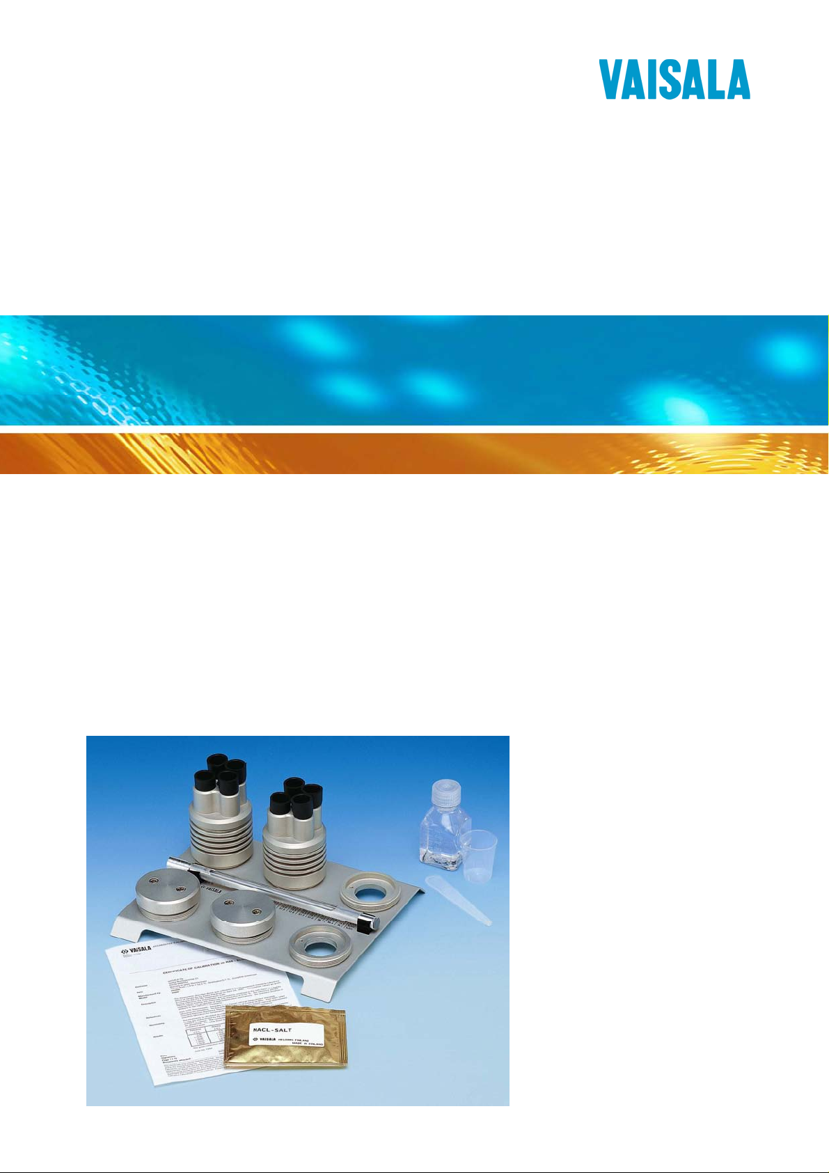
The HMK15 humidity calibrator has been developed for
calibration and checking of humidity probes and
transmitters. The functioning of the calibrator is based on
the fact that certain salt solutions generate a certain relative
humidity in the air above them.
The four holes in the chamber cover are designed for
Vaisala probe s and transmitters with 12 mm , 13.5 mm (2
holes) and 18.5 mm diameters.
The salt solutions suitable for the HMK15 calibrator are for
example lithium chloride LiCl (11 %RH), magnesium
chloride MgCl
and potassium sulphate K
In calibration, the sensor head is inserted into a salt chamber
containing a saturated salt solution. The probe/transmitter
reading is then adjusted to the correct value, that is to the
humidity that the specific salt solution generates at that
particular temperature.
(33 %RH), sod ium chloride NaCl (75 %RH)
2
(97 %RH).
2SO4
VAISALA __________________________________________________________7
Page 10
User's Guide________________________________________________________
Calibration is usually performed at least at two different
humidities to ensure the sensor accuracy over the entire
humidity range (0 … 100 %RH).
The HMK15 calibrator is suitable for both laboratory and
field usage. Du ring transportation, the chambers can be
tightly closed with specially designed transit covers. The
optional transit bag (order code HM27032) helps to
transport the calibrator in the vertical position. F urthermore,
the bag can be used for housing the calibrator also during
calibration.
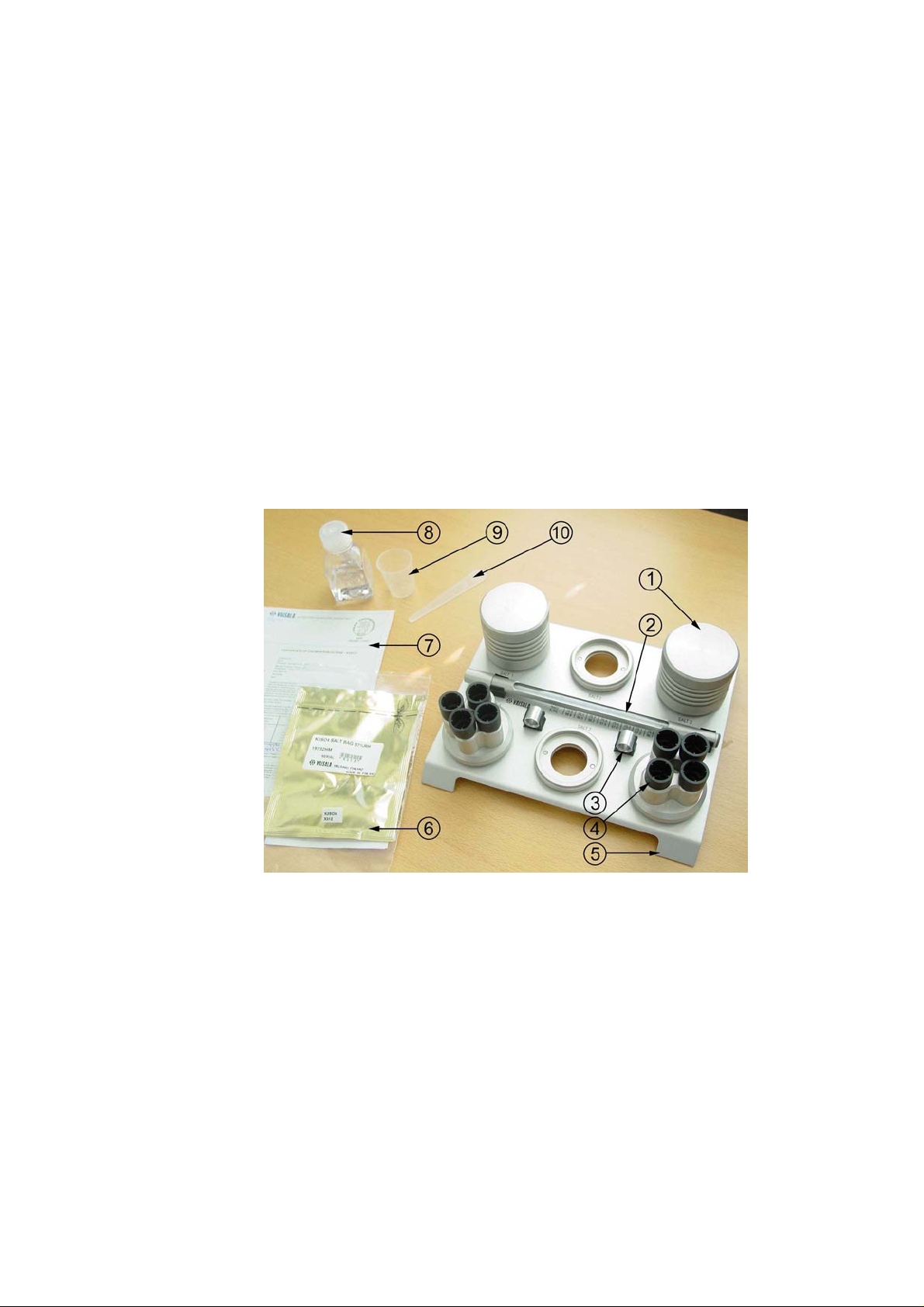
The following photo shows the HMK15 calibrator with
some accessories (marked with *):
0606-164
Figure 1 The HMK15 calibrator with some
accessories (*)
The following numbers refer to Figure 1 above:
1 =
Salt chamber
2 = Thermometer
3 = Adapter fitting
4 = Plugs
5 = Base plate
8 ______________________________________________________M210185EN-C
Page 11

Chapter 2 _____________________________________________Product Overview
6 = * Ready-dosed salt package with calibration
certificate
7 = Calibration certificate for thermometer
8 = * Ion-exchanged water
9 = Measurement cup
10 = Measurement spoon
Accessories include additional salt chambers, ion exchanged
water, transit ba g and ready-dosed salt packages (LiCl
11 %RH, MgCl
33 %RH, NaCl 75 %RH, K2SO4 97 %RH).
2
Salt Package Calibration Certificates
Vaisala's ready-dosed salt packages are delivered with
calibration certificates given on the basis of a batch check.
In other words, a sample of packages are taken from a batch
and salts are prepared according to the instructions given in
this manual. These salt solutions are then checked at Vaisala
Oy's Measurement St andards Laboratory (this calibration
laboratory is accredited by FINAS, a member of the
European Cooperation for Accreditation of Laboratorie s).
The calibration certificate certif ies th at the eq ui libr ium
humidities generated by these salt solutions correspond to
Greenspan's ca libration table within the specified accuracy
(see
Chapter 7 Technical Data on pa ge 35) .
VAISALA __________________________________________________________9
Page 12

User's Guide________________________________________________________
This page intentionally left blank.
10 _____________________________________________________M210185EN-C
Page 13

Chapter 3 _____________________________________Preparing the Salt Solutions
CHAPTER 3
PREPARING THE SALT SOLUTIONS
General Instructions
- Prepare the salts using the equipment provided with the
calibrator or make sure that all accessories used are
suitable for preparing salt solutions and are absolutely
clean. If necessary, wash them carefully and rinse several
times before preparing the salt solutions. The last rinse
must be made with distilled or ion exchange d water.
- The salts are quick and easy to prepare with Vaisala's
ready-dosed sa lt packages. If you do not use ready-dosed
salt packages, measure the salts using the measurement
cup provided. Make sure that the cup is clean before
measuring the salts. In the following instructions, the
required amounts are given in grammes and millilitres.
The salt solutions must be prepared from salts of pro
analysis grade; these are available in agencies selling
industrial chemicals. Note that the water must be distilled
or ion exchanged (conductivity < 0.25 µS/cm). Ion
exchanged water can also be ordered as an accessory for
the HMK15 calibrator (order code 19767HM).
- Handle the salts and equipment carefully and keep them
absolutely clean so that the salts are not contaminated.
Make sure that the salts do not mix.
VAISALA _________________________________________________________11
Page 14

User's Guide________________________________________________________
- At the bott om of the salt chamber there must not be more
than 1 cm of undissolved salt and liquid. Otherwise, the
sensor to be calibrated can be immersed into the solution.
If necessary, verify the amount for example with the
measurement spoon.
- Various standards (ASTM E104-8 5, DIN 50008, JIS
Z8806) include recommendations and instructions on
how to prepare and store salt solutions.
Preparing the Solutions
Lithium chloride ge nerates a reference humidity of
approximately 11 %RH. It is normally used as the dry end
(offset) reference.
NOTE
NOTE
NOTE
Never add water to dry LiCl salt; the salt may heat up so
rapidly that it splashes out of the chamber.
LiCl is harmful w hen swallowed; the solution is also
corrosive.
If the LiCl soluti on is used or stored in temperatures below
+18°C, its equil ibrium humidity changes permanently.
Magnesium chloride generates a reference humidity of
approximately 33 %RH. It is often used as a check point if
calibration is performed at more than two points.
Sodium chloride generates a reference humidity of
approximately 75 %RH. It is used as the wet end reference
(gain) for probes measuring in applications with normal
humidities.
12 _____________________________________________________M210185EN-C
Page 15

Chapter 3 _____________________________________Preparing the Salt Solutions
Potassium sulphate generates a reference humidity of
approximately 97 %RH. Potassium sulphate is used as the
wet end reference (ga in) for probes measuring in
applications with very high humidities (90 … 100 %RH, for
example outdoor and concrete measurements).
Prepare the salt solutions according to the following
instructions. Measure the salts carefully if you do not use
the ready-dosed packages.
1. Take the calibrat or out of the box. Open the transit
cover of the chamber. Remove the measurement cover
from the chamber holder a nd press the transit cover on
the holder (see
Figure 2).
0606-165
Figure 2 Press the transit cover on a chamber
holder
2. Pour ion exchanged water into the chamber; the
required amounts are given in the tab le:
LiCl 12 ml of water
MgCl2 3 ml of water
NaCl 10 ml of water
K2SO4 10 ml of water
VAISALA _________________________________________________________13
Page 16

User's Guide________________________________________________________
0606-166
Figure 3 Pour a correct dose of ion exchanged
water into the chamber; dry the
measurement cup
3. Sprinkle the contents of a salt package (or measure the
salt according to the table) in small quantities into the
chamber, stirrin g constantly. When measuring wi th the
measurement cup, make sure that the cup is clean and
dry. Rinse and dry the cup after every use.
LiCl 15 g or 18 ml
MgCl2 30 g or 30 ml
NaCl 20 g or 15 ml
K2SO4 30 g or 20 ml
14 _____________________________________________________M210185EN-C
Page 17

Chapter 3 _____________________________________Preparing the Salt Solutions
0606-167
Figure 4 Sprinkle a correct dose of salt into the
chamber stirring constantly
4. When all salt has been sprinkled into the chamber, the
saturated salt solution should have the ratio of
60 … 90 % undissolved salt to 10 … 40 % liquid.
5. Close the chamber with the cham ber cover (Figure 5).
VAISALA _________________________________________________________15
Page 18

User's Guide________________________________________________________
NOTE
0606-168
Figure 5 Close the chamber with the chamber
cover
6. Fasten the salt chamber on the holder in the base plate
and close the measurement hol es w ith rubber plugs.
The chambers can also be used as individual checkers
without the base plate.
The plugs have three steps, each of which is suitable for a
certain hole diameter: the first step for the 12 mm, the
second step for the 13.5 mm and the third step for the 18.5
mm hole. Keep the holes always closed when not
calibrating.
7. Write the preparation date on a sticker and mark the
chamber with it. If you use a ready-dosed salt package,
use the sticker with the batch code. Mark all parts of
the salt chamber (chamber, chamber cover and transit
cover) with stic kers. This way, various covers and
different salts do not get mixed.
16 _____________________________________________________M210185EN-C
Page 19

Chapter 3 _____________________________________Preparing the Salt Solutions
0606-169
Figure 6 Mark the chamber and covers with
stickers
8. Allow approximately 24 hours for stabilization before
use so that the salt solution reaches the equilibrium
humidity.
NOTE
9. See
Chapter 5 Maintenance on page 31 on how to
mai
ntain the salt solutions.
If you do not use the instrument for a longer period of time,
close the chambers with transit covers.
VAISALA _________________________________________________________17
Page 20

User's Guide________________________________________________________
This page intentionally left blank.
18 _____________________________________________________M210185EN-C
Page 21

Chapter 4 ________________Instructions for the Calibration of Humidity Instruments
CHAPTER 4
INSTRUCTIONS FOR THE CALIBRATION OF HUMIDITY INSTRUMENTS
General Instructions
Usually, the errors during humidity calibration are due to
temperature differences. A temperature difference of ±1 °C
at +20 °C between the air in the chamber and the sensor
causes an error of ±3 %RH at 50 %RH and an error of
±6 %RH at 97 %RH. The more the transportation or process
temperatures differ from the temperature at the calibration
site, the longer the stabilization time required. In laboratory
use, the calibrator should be store d in that part of the ro om
where the temperature is most stable. The calibrator must be
kept out of direct sunlight and away from localized heat
sources, such as spot lights, heaters and soldering irons. If
the probe/transm itt er is chec ke d agai nst se vera l humidity
references, the checking must first be made at the dry end.
More detailed instructions are given in individual manuals
of transmitter s and probes.
Handle the probe as little as possible. Do not hold the salt
chamber or other parts of the calibrator in ha nd du ring
calibration as they warm up and cause errors in the readings.
VAISALA _________________________________________________________19
Page 22

User's Guide________________________________________________________
NOTE
Even the smallest water drop on t he probe near th e sens or s
distorts the readings. Make sure that chamber covers and
plugs are carefully closed.
0606-170
Figure 7 Salt chamber
The following numbers refer to Figure 7 above
1 =
HMP233 probe
2 = O-rings
3 = Sensors
4 = Max. 1 cm
5 = Thermometer
6 = Saturated salt solution
7 = Undissolved salt
20 _____________________________________________________M210185EN-C
Page 23

Chapter 4 ________________Instructions for the Calibration of Humidity Instruments
Thermometer
The calibrator includes a thermometer which can contain
either mercury or red capillary liquid. If the thermom e ter
contains mercury, it is deliver e d with a calibration
certificate. The accuracy of the mercury thermometer is
sufficient for checking the transmitter's temperature channel
if desired. The mercury thermometer has been calibr ated at
five points and the result is traceable to the Measurement
Standards Laboratory of the Centre for Metrology and
Accreditation in Finland. For more accurate re sults, use the
corrections given in the calibration certificate or their
interpolated values. Consider also the parallax error which
may occur while reading the res ults. The mercury
thermometer should be recalibrated within three years in
order to maintain the traceability.
The manufacturer of the therm ometer with red capillary
liquid provides it with a factory calibration certificate. As
the accuracy and stability of this kind of a thermom eter are
inferior to those of a mercury thermometer, it is not
recommended to be used for checking the temperature
channel of the transmitter.
The sleeve at the end of the thermome ter's protective tube
can be used in two different positions. The thermometer is
delivered with the sleeve in such a position that it protects
the part contain ing the capillary liquid. When turned the
other way round, it acts as an adapter when the thermometer
is inserted into the 13.5 mm hole (see
Figure 8).
0606-171
Figure 8 The sleeve protects the part with capillary
liquid (on the left) or acts as an adapter (on
the right)
VAISALA _________________________________________________________21
Page 24

User's Guide________________________________________________________
During calibration, the thermometer is inserted into the
13.5 mm hole of a salt chamber. Press it downwards until it
passes the O-rings. The thermometer is correctly in place
when you can feel a resistance while pressing it dow nwards.
0606-172
Figure 9 During calibration, the thermometer is
inserted into the 13.5 mm hole
When the thermometer is not in use or the calibr at or is
transferred from one place to another, place the thermometer
in holders (Figure 10).
22 _____________________________________________________M210185EN-C
Page 25

Chapter 4 ________________Instructions for the Calibration of Humidity Instruments
0606-173
Figure 10 Place the thermometer in holders when not
in use
Calibration
Perform the calibra tion according to the following
instructions:
NOTE
- Leave the HMK15 calibra tor and the probe at the
calibration si te for at least 30 m inutes before starti ng the
calibration in order to let the prob e temperature stabilize
to the room temperature.
- With lithium chloride it i s not necessary to use the
thermometer as the humidity reading changes only very
slightly in the temperature range of +25 ... +30 °C.
However, if you use it make sure that the sleeve is in the
correct position and insert it into the 13.5 mm hole of the
LiCl salt chamber.
Handle the thermometer as little as possible and do not
handle it by the measuring end. Press the thermometer
downwards until it passes the O-rings. The thermometer is
correctly in place when you feel a resistance while pressing
it downwards.
VAISALA _________________________________________________________23
Page 26

User's Guide________________________________________________________
- Take off the g r id or filter protect ing the sensor. Ta ke care
not to damage the sensor.
- Some 12 mm probes need a adapter fitting to fit into the
13.5 mm hole. Adapter fitting prevents sensor f rom
soaking in the salt liqui d. In case y ou nee d an adapter
fitting, take off the grid or filter and replace it with the
adapter fitting. Two adapter fittings are attached on the
base plate of the HMK15, see
Figure 1 on page 8.
CAUTION
Remember to check fr om the user's guide of y our device if
the adapter fitti ng is needed. If sensor accidently soaks in
salt liquid, remove it quickly and rinse with clean water.
Let it dry before taking into use again.
- Insert the probe into a suitable hole of the LiCl salt
chamber. Press it downwards until it passes the O-rings.
The shorter the time the hole stays open before inserting
the probe, the shorter the stabiliz ation time required.
- Wait until the humidity reading stab ilize s; th is ta ke s
about 10 … 30 m inutes.
- Read the salt chamber temperature from the thermometer
and then read the closest humidity value from the
calibration table (Greenspan's Calibration Table
5, LiCl solution).
2
on page
- Adjust the dry end (DRY, offset) to correspond to the
value given in the calibration table.
- Insert the thermometer into the 13.5 mm hole of the NaCl
salt chamber.
NOTE
When calibrating probes that are being used for long term
measurements (over 1 hour) in high humidities
(90 … 100 %RH), use the K
salt as the high end
2SO4
reference.
24 _____________________________________________________M210185EN-C
Page 27

Chapter 4 ________________Instructions for the Calibration of Humidity Instruments
- Insert the probe into a suitable hole of the NaCl (or
K
) salt chamber. The shorter the time the hole stays
2SO4
open before inserting the probe, the shorter the
stabilization time required.
- Wait until the humidity reading stab ilize s; th is ta ke s
about 10 … 30 minutes. Note that in high humidities the
risk for errors increases. Therefor e, the stabilization time
should be longer (approximately 20 … 40 minutes).
- Read the salt chamber temperature from the thermometer
and then read the closest humidity value from the
calibration table (Greenspan's Calibration Table below,
NaCl
or K
2SO4
solution).
- Adjust the wet end (WET, gain) to correspond to the
value given in the calibration table.
Greenspan's Calibration Table
C LiCl MgCl2 NaCl K2SO4
0 * 33.7 ± 0.3 75.5 ± 0.3 98.8 ± 1.1
5 * 33.6 ± 0.3 75.7 ± 0.3 98.5 ± 0.9
10 * 33.5 ± 0.2 75.7 ± 0.2 98.2 ± 0.8
15 * 33.3 ± 0.2 75.6 ± 0.2 97.9 ± 0.6
20 11.3 ± 0.3 33.1 ± 0.2 75.5 ± 0.1 97.6 ± 0.5
25 11.3 ± 0.3 32.8 ± 0.2 75.3 ± 0.1 97.3 ± 0.5
30 11.3 ± 0.2 32.4 ± 0.1 75.1 ± 0.1 97.0 ± 0.4
35 11.3 ± 0.2 32.1 ± 0.1 74.9 ± 0.1 96.7 ± 0.4
40 11.2 ± 0.2 31.6 ± 0.1 74.7 ± 0.1 96.4 ± 0.4
45 11.2 ± 0.2 31.1 ± 0.1 74.5 ± 0.2 96.1 ± 0.4
50 11.1 ± 0.2 30.5 ± 0.1 74.4 ± 0.2 95.8 ± 0.5
The numbers on the right in each column indicate the uncertainty of the reference humidity of
the salt in that temperature.
1) Greenspan, L.: Journal of Research of the National Bureau of Standards - A Physis and
Chemistry Vol. 81A, No. 1 January-February 1977, pp. 89-95
1
VAISALA _________________________________________________________25
Page 28

User's Guide________________________________________________________
On-Site Calibrations and Transportation
The HMK15 calibrator is easily trasferred from one place to
another. Two O-rings seal the transit cover on the chamber.
The optional transit bag helps to transport the calibrator so
that chambers stay in the vertical posit ion. Fur thermore, the
bag can be used for housing the calibrator during
calibration.
0606-174
Figure 11 Optional Transit Bag for HMK15
When transferring the calibrator from one place to another,
follow the instructions below:
- Turn the protective sleeve on the thermometer and place
the thermometer in the holder.
- Replace chamber covers with transit covers. Press
chamber covers on vacant chamber holders for
transportation.
- During transportation, keep the calibrator so that the
chambers stay as upright as possible. This way, very litt le
salt solution gets on transit covers and cleaning is easier.
The closer the transportation temperature is to the
temperature of the calibration site, the shorter the time
required for temperature stabilization. If the
26 _____________________________________________________M210185EN-C
Page 29

Chapter 4 ________________Instructions for the Calibration of Humidity Instruments
transportation temperature is below +18 °C, the LiCl salt
chamber should be transported separately to keep the
solution warm.
- When the calibrator is at the calibration site, remove
transit covers and fasten c hamber covers on salt
chambers. Close the holes with plugs.
NOTE
The plugs have three steps each of which is suitable for a
certain hole diameter: the first step for the 12 mm, the
second step for the 13.5 mm and the third step for the
18.5 mm hole.
- Clean the transit covers with a damp cloth and pres s them
on vacant chamber holders.
- Take the thermometer off the holder, turn the sleeve the
other way round a nd perform the calibration according to
section Calibration on page 23.
on-site calibrations it is important to allow enough time
In
for the calibrator and probe temperatures to stabilize.
Depending on the temperature differences between the
transportation and the calibration site or between the probe
removed from the process and the calibr ation site, a two
point calibration takes about 0.5 … 2 hours. If there are
several frequently calibrated instruments at the same site,
knowing the stabilization times is useful.
VAISALA _________________________________________________________27
Page 30

User's Guide________________________________________________________
The following figure illustrates an example of temperature
and humidity stabilization. In this example, an HMP233
probe has been transferred from a temperature of 75 °C
(oven) to a suitable hole of the NaCl salt chamber; the
calibrator is at room temperature. The figure shows that
after 40 minutes, the humidity reading differs 0.2 % RH
from the final reading.
0606-175
Figure 12 An example of RH and T stabilization when
the probe is removed from a process
28 _____________________________________________________M210185EN-C
Page 31

Chapter 4 ________________Instructions for the Calibration of Humidity Instruments
In the following example, the tran sportation temperature of
the calibrator (without the LiCl) is +5 °C; the calibrator is
then transferred into room temperature. After this, an
HMP233 probe that has been stored at room temperature, is
inserted into a suitable hole of the NaCl salt chamber. The
figure shows that after 40 minutes, the reading differs
1.4 %RH from the final reading.
0606-177
Figure 13 An example of the RH and T s t abilization
when the transportation and calibration site
temperatures are different
VAISALA _________________________________________________________29
Page 32

User's Guide________________________________________________________
This page intentionally left blank.
30 _____________________________________________________M210185EN-C
Page 33

Chapter 5 ________________________________________________ Maintenance
CHAPTER 5
MAINTENANCE
Depending on the frequency of use and the general
operating conditions, the salt solutions maintain their
characteristic s for 6 … 12 months. After that, they must be
replaced. A visual c heck should be performed at intervals of
2 … 3 months. There must be a minimum of approximately
10% of undisso lved salt at the bo ttom of the chamber
(max. 90 %) a nd the salt must be clean, otherwise it must be
reprepared. Please, note that the LiCl solution may
crystallize on the surface. However, there may still be
solution under the surface. Therefore, in such cases stir the
solution and check it again the next day. It is advisable to
keep a maintenance log which shows the dates of salt
replacements and other maintenance procedures.
For correct calibration it is essential that salt chambers are
tightly closed. Check the O-rings at each salt re placement. If
they are damaged, replace them with new ones. The O-rings
used are of the fo llowing types:
O-ring location dimensions type
measurement hole
12 mm
measurement hole
13.5 mm
measurement hole
18.5 mm
transit cover 41.2 v 3.0 mm NBR70
chamber 50.0 × 2.0 mm NBR70
VAISALA _________________________________________________________31
12 × 2.5 mm NBR70
13.5 × 2.5 mm NBR70
18.3 × 2.4 mm NBR70
Page 34

User's Guide________________________________________________________
This page intentionally left blank.
32 _____________________________________________________M210185EN-C
Page 35

Chapter 6 ____________________________________Spare Parts and Accessories
CHAPTER 6
SPARE PARTS AND ACCESSORIES
Order code Description
19728HM Mercury thermometer with
calibration certificate
25130HM Thermometer with red
capillary liquid
19729HM Ready-dosed LiCl salt
package with calibration
certificate
19730HM Ready-dosed MgCl2 salt
package with calibration
certificate
19731HM Ready-dosed NaCl salt
package with calibration
certificate
19732HM Ready-dosed K2SO4 salt
package with calibration
certificate
19746HM Plug set
19766HM Salt chamber
19767HM Ion exchanged water
211302SP Adapter fitting for 12 mm
probes (spare part)
HM27032 Transit bag
VAISALA _________________________________________________________33
Page 36

User's Guide________________________________________________________
This page intentionally left blank.
34 _____________________________________________________M210185EN-C
Page 37

Chapter 7 _______________________________________________Technical Data
CHAPTER 7
TECHNICAL DATA
Operating temperature range +0 ... +50 ºC
NOTE
If the LiCl soluti on is used or stored in temperatures below
+18 ºC, its equil ibrium humidity changes permanently.
Accuracy:
lithium chlor ide LiCl ±1.0 %RH +
Greenspan's
uncertainty*
magnesium chloride MgCl
±1.0 %RH +
2
Greenspan's
uncertainty*
natrium chloride NaCl ±1.4 %RH +
Greenspan's
uncertainty*
potassium sulphate K
±1.5 %RH +
2SO4
Greenspan's
uncertainty*
*) The uncertainty given in Greenspan's calibration table (on page 25) at the calibration
temperature, for example the accuracy of LiCl salt at +20 °C is ±(1.0 + 0.3) %RH
= ±1.3 %RH
VAISALA _________________________________________________________35
Page 38

User's Guide________________________________________________________
Response time (probe and calibrator
at the same temperature) with Vaisala sensors
typically 10 min
(deviation of the final
value < ±1 %RH)
Accuracy of the thermometer:
with mercury ±0.3 °C
with red capillary liquid ±1 °C
Dimensions 0 × 9 × 23 cm
Materials metal parts: anodised
aluminium
Weight 1 kg without salt
solutions
36 _____________________________________________________M210185EN-C
Page 39

*M210185
EN
*
www.vaisala.com
 Loading...