

Page 1

r
OPERATING MANUAL
HMI41 Indicato
and HMP42 Probe
U323en-1.1
Page 2

© Vaisala Oy 1998
No part of this document may be reproduced in any form or by any
means, electronic or mechanical (including photocopying), nor may
its contents be communicated to a third party without a prior written
notice of the copyright holder.
The instruction manuals may be changed without prior notice.
Yleisjäljennös 3/1998
Page 3

HMI41 AND HMP42
U323en-1.1 Operating Manual
Contents
1. THE HMI41 INDICATOR AND PROBES..................................................................................1
2. TO BE NOTED IN THE M EASUREMENT OF HUM IDIT Y ......................................................... 3
3. GETTING STARTED................................................................................................................ 4
3.1 Inserting the batteries .................................................................................................. 4
3.2 Connecting the HMP42 probe ...................................................................................... 4
3.3 Starting the measurements..........................................................................................4
3.4 Using the HMP42 for measuring equilibrium humidity in structures.........................5
3.4.1 Example 1: measuring hum idity in a bathroom ................................................5
3.4.2 Example 2: measuring hum idity in a concrete floor..........................................6
3.4.3 Erroneous installations .................................................................................... 7
4. HOW TO USE THE HM I41 INDICATOR AND HMP42 PROBE ................................................. 8
4.1 Turning the indicator on............................................................................................... 8
4.2 Measurement readings on display ............................................................................... 9
4.3 HOLD-mode................................................................................................................. 10
4.3.1 MIN-mode ..................................................................................................... 10
4.3.2 MAX-mode .................................................................................................... 10
5. CALIBRATION....................................................................................................................... 11
5.1 How to use the HMP42 calibration adapter ............................................................... 11
5.2 Calibration with trimmer potentiometers .................................................................. 12
5.2.1 Humidity calibration....................................................................................... 12
5.3 Calibration with HMI41 software commands............................................................. 14
5.3.1 One point humidity calibration........................................................................ 16
5.3.2 Two point humidity calibration........................................................................ 18
5.3.3 One point temperature calibration.................................................................. 20
5.3.4 Two point temperature calibration.................................................................. 22
6. HMI41 AND DATA COLLECTING.......................................................................................... 25
6.1 Entering the data collecting mode............................................................................. 25
6.2 Manual data collecting ...............................................................................................26
6.3 Setting the measurement duration ............................................................................ 27
6.4 Setting the measurement interval.............................................................................. 27
6.5 Reading the measurement results............................................................................. 28
6.5.1 MIN and MAX in data collecting
REC READ mode............................................ 30
7. TRANSFERRING THE STORED READINGS TO A PC.......................................................... 31
7.1 Giving the communication parameters ..................................................................... 31
7.2 Transferring the data.................................................................................................. 34
7.2.1 PLAY Transferring the data ........................................................................... 34
7.2.2 CPLAY Setting characters between decimals and fields ................................ 35
7.2.3 HELP Outputting all available commands and their contents ..................... 36
7.3.4 ? Outputting the HMI41 settings .................................................................... 36
i
Page 4

HMI41 AND HMP42
Operating Manual U323en-1.1
8. SETUP PROCEDURE ............................................................................................................37
8.1 Entering the setup mode ............................................................................................37
8.2 Selecting the display units......................................................................................... 38
8.3 Setting the automatic power-off function..................................................................39
8.4 Selecting the display quantities.................................................................................39
8.5 Setting the pressure for mixing ratio and wet bulb temperature calculations .......40
8.6 Selecting the probe type.............................................................................................40
9. MAINTENANCE .....................................................................................................................41
9.1 Changing the filter and the sensor head set ............................................................. 41
9.2 Chemical tolerances of the HUMICAP
MINI sensor ..................................................41
9.3 Spare parts and accessories...................................................................................... 42
10. IN CASE OF ERROR............................................................................................................43
10.1 Trouble shooting .......................................................................................................43
10.2 Checking the settings............................................................................................... 44
11. TECHNICAL DATA............................................................................................................... 45
11.1 HMI41 indicator .........................................................................................................45
11.2 HMP42 probe .............................................................................................................46
11.2.1 Relative humidity........................................................................................... 46
11.2.2 Temperature................................................................................................ 46
11.2.3 General........................................................................................................47
11.4 Accuracy of the calculated quantities......................................................................48
11.4.1 Accuracies in metric units ............................................................................ 48
11.4.2 Accuracies in non-m etric units ..................................................................... 49
11.5 Electromagnetic compatibility..................................................................................51
11.5.1 Emissions....................................................................................................51
11.5.2 Immunity......................................................................................................51
APPENDIX 1: QUICK REFERENCE GUIDE ...............................................................................53
WARRANTY...................................................................................................................................
This manual is valid for programme versions 2.01 or greater.
ii
Page 5

HMI41 AND HMP42
U323en-1.1 Operating Manual
1. THE HMI41 INDICATOR AND PROBES
The HMI41 is an easy-to-use portable humidity and temperature indicator for
a variety of applications, including such as industrial monitoring and
inspections, occupational health and safety, laboratory and research use, spot
checking etc. When equipped with optional calibrati on cables, the HMI41 can
also be used as a field calibrator for most Vaisala transmitters.
The HMI41 has as many as six different probe types to choose from. The
indicator recognizes the probe type automatically, so there is no need to
change settings each time the probe is changed. However, please, note that this
feature is active only in indicators and probes with letters ID in the instrument
label. For previous versions, the probe type has to be set manually. The
HMP44 is an exception, as indicators marked with ID recognize automatically
all versions of this probe. All probe types are optimized for different
applications:
• HMP41 probe can be used for measuring humidity and temperature in
numerous applications, for example in spot checks.
• HMP42 probe head has a diameter of only 4 mm. The HMP42
consists of a handle a 23.5 cm long probe head. This remarkably small
and round probe structure is specially indicated for measurements in
very tight spaces, e.g. in joint spaces between tiles and in air
conditioning channels, as well as for measuring the equilibrium
humidity of e.g. timber; the operating temperature range is
-40 - +100 °C.
• HMP44 and HMP44L are used for measuring humidity in concrete
and other structures.
• HMP45 probe is indicated for measurements in channels and other
places that are difficult to reach and therefore require a probe head
with cable.
• HMP46 probe is optimized for measurements in relatively high
temperatures (up to +100 °C, temporarily even +180 °C), in dirty
processes and in general in applications that require a robust probe
structure.
The HMI41 indicator displays relative humidity, temperature and dewpoint
temperature readings. In addition to these, one of the following quantities can
also be chosen: absolute humidity, wet bulb temperature or mixing ratio.
The indicator also features an automatic power-off function which can be
disabled, and a continuously updated display. The display can be frozen to
1
Page 6

HMI41 AND HMP42
Operating Manual U323en-1.1
show the current readings, and it can be used for checking the minimum and
maximum readings measured during data collecting. The automatic power-off
function is not active during data collecting even if it was previously selected.
The versatile HMI41 indicator also includes a data collecting feature. Data
collecting can be either automatic or manual, and it can be optimized for each
application: both the measurement interval and duration can be set by the user.
During automatic data collecting, the probe takes measurements only just
before storing each measurement. In order to minimize the consumption and to
maximize the battery life, the power is automatically turned off for the
measurement interval and the display is dim except when the readi ngs on the
display are updated (once a minute). The stored readings can be transferred to
a PC via a serial interface (order code 19446ZZ) and then printed, if required.
The humidity measurement range is 0 - 100 %RH. The temperature measure-
ment range with the HMP42 probe is -40 - +100 °C. Relative humidity is
measured with the accurate and stable HUMICAPMINI humidity sensor
which uses an operating principle based on the changes in the capacitance of
the sensor as its thin polymer film absorbs water molecules.
2
Page 7
HMI41 AND HMP42
U323en-1.1 Operating Manual
2. TO BE NOTED IN THE MEASUREMENT OF HUMIDITY
In the measurement of humidity and especially in calibration it is essential that
temperature equilibrium is reached. Even a small difference in temperature
between the measured object and the sensor causes an error. If the t emperature
is +20 °C (+68 °F) and the relative humidity is 50 %RH, a difference of +1 °C
between the measured object and the sensor causes an error of +3 %RH. When
the humidity is 90 %RH, the corresponding error is + 5.4 %RH.
The error is at its greatest when the sensor is colder or warmer than the
surroundings and the humidity is high. Although the humidity sensor reacts
rapidly to changes in the amount of water vapour in the air, the probe
temperature changes more slowly. To avoid errors caused by temperature
differences the probe must always be left to stabilize to ambient temperature
before starting measurements: the bigger the temperature difference, the
longer the stabilization time.
Indoors relative humidity should be measured in a place where the temperature
is as close to the average temperature of the room as possible. Measurements
taken close to heat sources will not give a true picture of the relative humidity
in the whole room.
10
9
8
7
6
5
4
dRH (%RH)
3
2
1
0
-40-200 20406080100
Temperature (°C)
Figure 2.1 Measurement error at 100 %RH when the dif ference
between the ambient and the sen sor temperature is 1 °C
3
Page 8

HMI41 AND HMP42
Operating Manual U323en-1.1
3. GETTING STARTED
3.1 Inserting the batteries
When taking the HMI41 indicator into use, first insert the batteries (4 pcs of
size AA [LR6] batteries). Open the lid on back of the device and insert the
batteries as indicated in the housing. Then close the lid carefully.
3.2 Connecting the HMP42 probe
Connect the HMP42 probe cable to the connector marked 'PROBE' at the
bottom of the HMI41 indicator (see Figure 3.2.1).
NOTE
If the indicator does not have letters ID in the
instrument label (on the back of the indicator), you
must give the probe setting manually before starting the
measurements (see Chapter 8).
HMP42
cable
Figure 3.2.1 Connecting the HMP42 probe to the HMI41
3.3 Starting the measurements
Before starting the measurements with the HMP42, remember to allow enough
time for stabilization.
Turn the power on with the ON/OFF button and the following appears:
RH
Td
T
P
set min max hyst hold Lo bat Hi
%
°C °F
°C
°F
Pahg/m
Within a couple of seconds, the display changes to show the software version
and the probe type (42.46):
4
Page 9
HMI41 AND HMP42
U323en-1.1 Operating Manual
NOTE: if the following appears, check that the probe is correctly connected:
If the software version does not appear, it is smaller than 1.02 and the
indicator cannot be used with the HMP42 probe. If the probe type does not
appear, the indicator is of a previous version and does not recognize the probe
type automatically; give the setting manually (see Chapter 8).
In a couple of seconds, the battery charge appears and after that, the first
measurement readings:
RH
T°C
More detailed instructions of use are given in Chapter 4.
%
3.4 Using the HMP42 for measuring equilibrium humidity in structures
The HMP42 has been optimized for taking measurements in structures and
tight places. The following photos illustrate some examples of use in these
applications.
3.4.1 Example 1: measuring humidity in a bathroom
In this example, the screw of the shower holder is removed; no drilling is
needed as the HMP42 is small enough to enter this screw hole.
Figure 3.4.1 Taking measurements in a bathroom
5
Page 10

HMI41 AND HMP42
Operating Manual U323en-1.1
3.4.2 Example 2: measuring humidity in a concrete floor
Bore a hole and clean it thoroughly so that all drilling dust comes out; blowing
air is a good method for cleaning. However, please, note that if you clean
several holes, you should use a mask to protect yourself against dust. You can
also use a vacuum cleaner. Seal the hole e.g. with tape. Let stabilize (e.g. 24
hours in concrete). Cut the tape, insert the probe in the hole and take
measurements. See photos below for steps 1 - 6.
1. Bore a hole. 2. Clean it. 3. Seal it and let stabilize.
4. Cut the tape. 5. Insert the probe. 6. Take measurements.
Figure 3.4.2 Taking measurements in concrete floors
6
Page 11

HMI41 AND HMP42
U323en-1.1 Operating Manual
3.4.3 Erroneous installations
Please, note that although with a metal probe head, the HMP42 is a delicate
instrument and requires careful handling. The probe must never be strongly
bent or forced through anything; if necessary, use e.g. a sharp edged pin with a
diameter of 5 mm. The filter must not be twisted. When taking measurements
in structures, never leave the cable and indicator hanging down while leaving
the probe to stabilize (see photos below). Make sure that when mounted
horizontally, the probe is at least 4 cm inside the structure in order to avoid
bending. See the following photos and make sure that your installation is not
like the one on the right.
at least 4 cm
inside the
structure
Figure 3.4.3 Installation: correct way on the left,
erroneous on the right
7
Page 12
HMI41 AND HMP42
Operating Manual U323en-1.1
4. HOW TO USE THE HMI41INDICATOR AND HMP42 PROBE
4.1 Turning the indicator on
To start the measurements with the HMI41, just press the ON/OFF button and
the following text appears:
RH
Td
T
P
set min max hyst hold Lo bat Hi
%
°C °F
°C
°F
Pahg/m
After a few seconds, the software version and probe type indication appear:
If the software version does not appear, it is smaller than 1.02 and the HMI41
cannot be used with the HMP42. Contact Vaisala or a Vaisala representative
for further information.
Make sure that you can see the text 42.46 on the display. If not, the indicator
is of a previous version and does not recognize the probe type automatically.
Give the probe type setting manually (see Chapter 8).
After a couple of seconds, the battery voltage appears on the display with an
indication of the battery charge (high or low):
Hi
bat
If the battery voltage is higher than 4.75 V, the text on the lower righthand
corner is “bat HI” and after a few seconds, the HMI41 automatically displays
the RH and T readings. If the voltage is 4.65...4.75 V, the text is “Lo bat” and
the batteries should be replaced (see Chapter 3.1). If the voltage is lower than
4.65 V, the indicator turns itself off to prevent erroneous measurements and
readings. Should this happen, replace the batteries.
8
Page 13
HMI41 AND HMP42
U323en-1.1 Operating Manual
4.2 Measurement readings on display
Relative humidity and temperature readings appear automatically after the
battery charge indication:
RH
%
T°C
If MODE button is pressed, dewpoint temperature (Td) reading is displayed:
Td
T
When the MODE button is pressed again, one of the following is displayed or
°C
°C
the HMI41 returns to showing the RH and T readings according to what has
been chosen for the measurement quantities (see Chapter 4.4):
°C
g/m
Temperature and absolute humidity
T
abs
T
°C
°C
Temperature and wet bulb temperature; the
arrow in the lower righthand corner indicates that
wet bulb temperature has been chosen
T
°C
Temperature and mixing ratio; the arrow in the
lower righthand corner indicates that mixing ratio
has been chosen (the unit is g/kg or gr/lb).
9
Page 14
HMI41 AND HMP42
Operating Manual U323en-1.1
4.3 HOLD-mode
In any of the previously mentioned measurement reading displays, the HOLD
button freezes the display to show the current readings, e.g. RH & T readings:
RH
T
With MODE or ENTER, the display returns to the normal display mode.
If the indicator turns itself off with the automatic power-off function during
%
°C
hold
the HOLD-mode, it wakes up in the same mode when turned on again. The
'hold'-text is blinking and the indicator can be returned to the normal display
mode with any button except ON/OFF.
4.3.1 MIN-mode If you wish to know the minimum readings that have been measured after
power up, press HOLD when the indicator is in the HOLD-mode. The
minimum readings of the currently displayed quantities are shown (if the
‘hold’-text is blinking, the HMI41 must first be returned to the normal display
mode in order to activate the MIN-mode; see Chapter 4.3 above):
RH
T
min
With MODE or ENTER, the indicator returns to the normal display mode.
4.3.2 MAX-mode If you wish to know the maximum readings that have been measured after
%
°C
power up, press HOLD when the indicator is in the MIN-mode. The maximum
readings of the currently displayed quantities are shown:
RH
T
max
The indicator returns to the normal display mode with any button except
%
°C
ON/OFF.
10
Page 15

HMI41 AND HMP42
U323en-1.1 Operating Manual
5. CALIBRATION
5.1 How to use the HMP42 calibration adapter
As the HMP42 probe diameter is extremely small, the probe has a special
calibration adapter for inserting the probe into a salt chamber (e.g. in the
HMK15 calibrator).
NOTE
Be extremely careful when inserting the probe into the
calibration adapter: do not bend or break it.
The probe is inserted into the adapter with the steel grid on; this protects the
sensor and prevents it from breaking. Unlike other humidity probes, the
HMP42 is calibrated with the steel grid on and thus, the probe naturally
requires a slightly longer stabilization time (approx. 30 minutes).
Figure 5.1.1 HMI41, HMP42 and calibration accessories
Figure 5.1.2 Insert the probe head into the calibration adapter
11
Page 16
HMI41 AND HMP42
Operating Manual U323en-1.1
5.2 Calibration with trimmer potentiometers
5.2.1 Humidity calibration The HMI41 indicator and HMP42 probes are fully calibrated at the factory, so
there should be no immediate need for re-calibration. Calibration should be
performed only if there is a strong reason to believe that the adjustments have
changed.
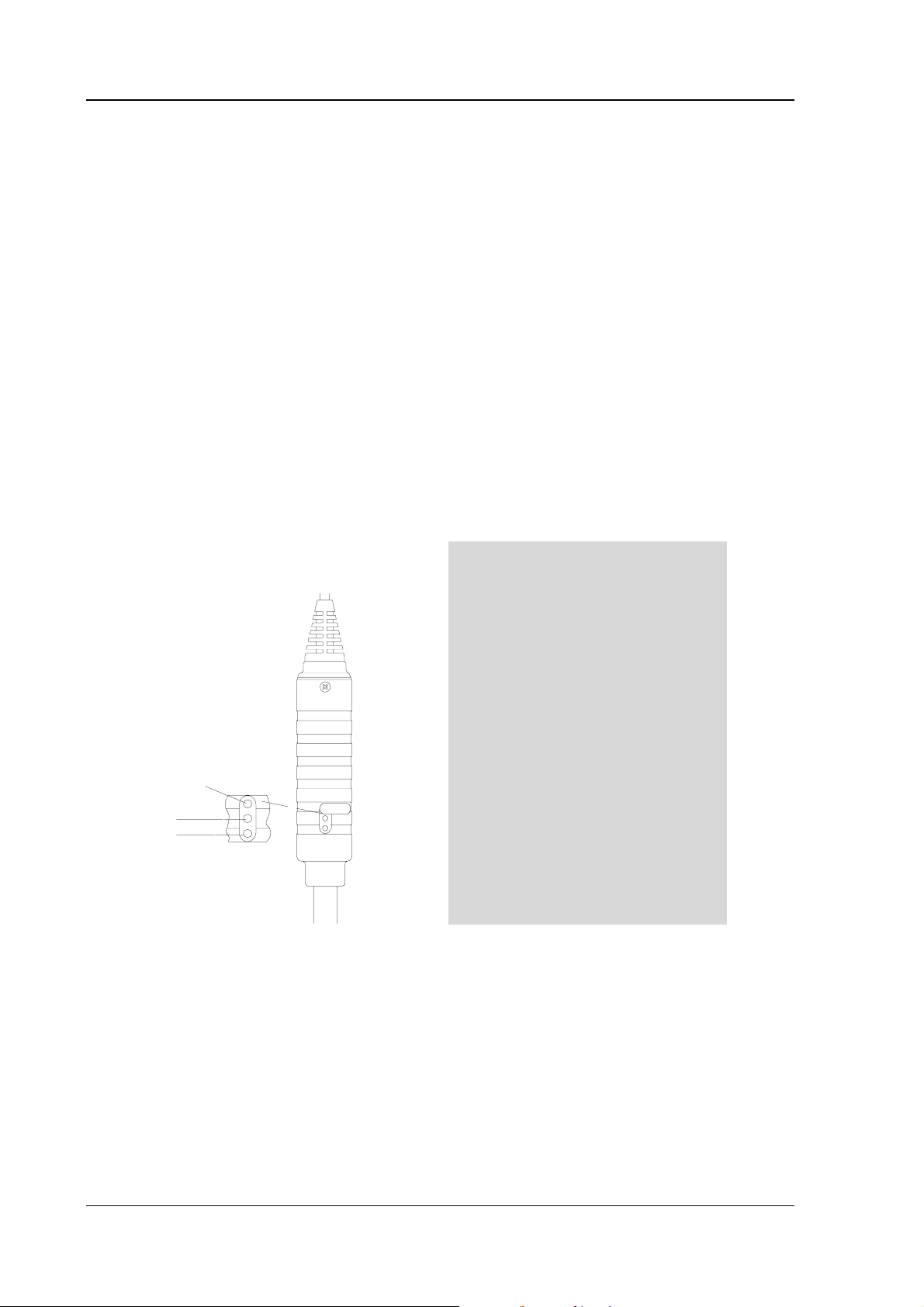
Humidity calibration of the HMP42 probe is done by adjusting trimmer
potentiometers. The potentiometers are located under a protective plug. The
potentiometer marked T (temperature) is for factory use only; DO NOT make
any adjustments. To make sure that this potentiometer is not accidentally
touched when adjusting the other two, turn the plastic plug aside without
removing it completely (see Figure 5.2.1).
For adjusting the potentiometers, use a trimming wrench provided with the
probe, or some other suitable tool, e.g. a ceramic 1.5 mm slot screwdriver.
12
T
wet
W
D
W
D
dry
Figure 5.2.1 Adjusting the trimmer potentiometers
A two point calibration is performed with the HMK15 or the HMK13B
Calibrator or the probe can be sent to Vaisala. The probes must always be recalibrated if the sensor head set is changed.
Page 17

HMI41 AND HMP42
U323en-1.1 Operating Manual
The calibration procedure is as follows (see also the calibrator manual):
• Leave the calibrator and the probe at the calibration site for at least 30
minutes before starting the calibration in order to let the probe
temperature stabilize to the room temperature.
• Insert the probe into a measurement hole of the LiCl salt chamber (see
Figure 5.2.2).
Figure 5.2.2 The HMP42 in a salt chamber of the
HMK15 calibrator
• Wait until the humidity reading stabilizes (approx. 30 minutes).
Check the temperature and read the closest humidity value in the
calibration table. Adjust the dry end reading with the potentiometer D
(dry) in the probe body to correspond to the value given in the
calibration table; use a suitable trimming screw wrench (see Figure
5.2.1).
• Insert the thermometer into the 13.5 mm hole of the NaCl salt
chamber and the probe into another hole of the NaCl chamber.
NOTE
When calibrating probes that are being used for long
term measurements (over 1 hour) in high humidities
(90 - 100 %RH), use the K2SO4 salt as the high end
reference.
• Wait until the humidity reading stabilizes. Read the salt chamber
temperature from the thermometer and then the closest humidity value
from the calibration table. Adjust the wet end reading with the
potentiometer W (wet) to correspond to the value given in the
calibration table.
13
Page 18

HMI41 AND HMP42
Operating Manual U323en-1.1
Table 5.2 Greenspan’s calibration table
°C
LiCl NaCl K2SO
4
0 * 75.5 98.8
5 * 75.7 98.5
10 * 75.7 98.2
15 * 75.6 97.9
20 11.3 75.5 97.6
25 11.3 75.3 97.3
30 11.3 75.1 97.0
35 11.3 74.9 96.7
40 11.2 74.7 96.4
45 11.2 74.5 96.1
50 11.1 74.4 95.8
* If the LiCl solution is used or stored in temperatures below +18°C, its equilibrium
humidity changes permanently
As the D (dry) and W (wet) adjustments may affect each other, check again
the humidity reading in the LiCl salt chamber: insert the probe into the
calibration hole and wait until the reading stabilizes. If necessary, repeat the
adjustments in both the LiCl and the NaCl (K2SO4) salt chambers until the
reading is correct.
5.3 Calibration with HMI41 software commands
Calibration can also be done with the HMI41 software commands by entering
the corrections in the indicator memory with pushbuttons. If only one probe is
being used, the HMI41 software calibration is useful. However, when several
probes are in use, it is recommended that calibration is done by adjusting the
probe potentiometers. Note that when the sensor head set is changed,
calibration must always be done by adjusting the potentiometers and it is
recommended that the HMI41 is reverted to factory settings by selecting
default calibration.
NOTE
If the factory calibration of the HMI41 is changed, the
correction data refers to the calibrated probe only.
Therefore, if you change the probe, always revert this
data to factory settings by selecting default calibration,
or perform a new calibration with the new probe.
14
Page 19
HMI41 AND HMP42
U323en-1.1 Operating Manual
The calibration procedure is included in the HMI41 setup mode. For entering
the setup mode, first press the ON/OFF button and the following appears:
RH
Td
T
P
set min max hyst hold Lo bat Hi
%
°C °F
°C
°F
Pahg/m
Then release the ON/OFF button and press within 1...2 seconds both ENTER
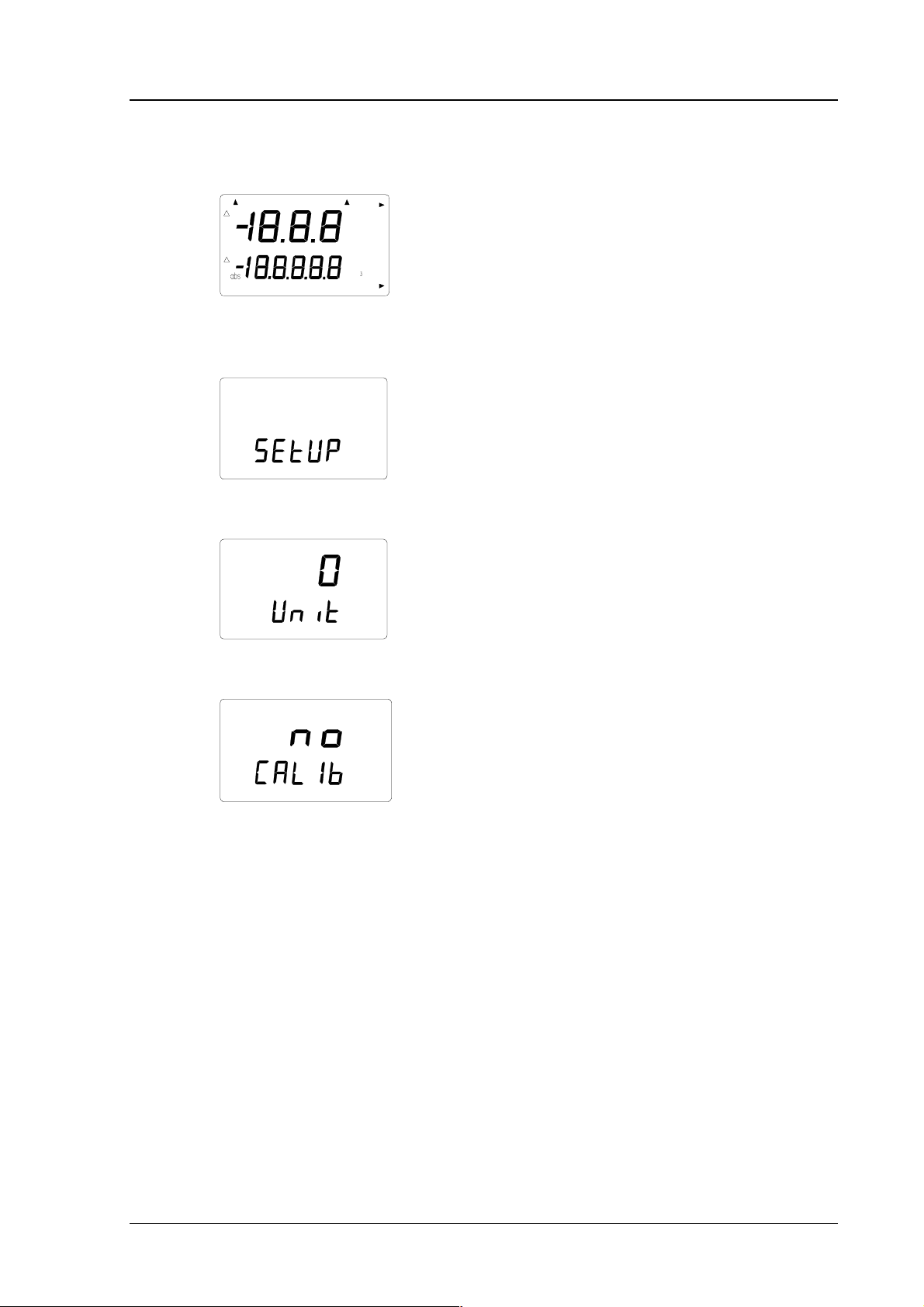
and MODE buttons until the following text appears on the display:
After a few seconds, the text changes automatically to show the following:
°C
set
Press ENTER eight times until the following text appears:
set
This indicates that no calibration has been selected. In addition to this, there
are five calibration types available. The desired type is selected with buttons
▲ or ▼.
15
Page 20
HMI41 AND HMP42
Operating Manual U323en-1.1
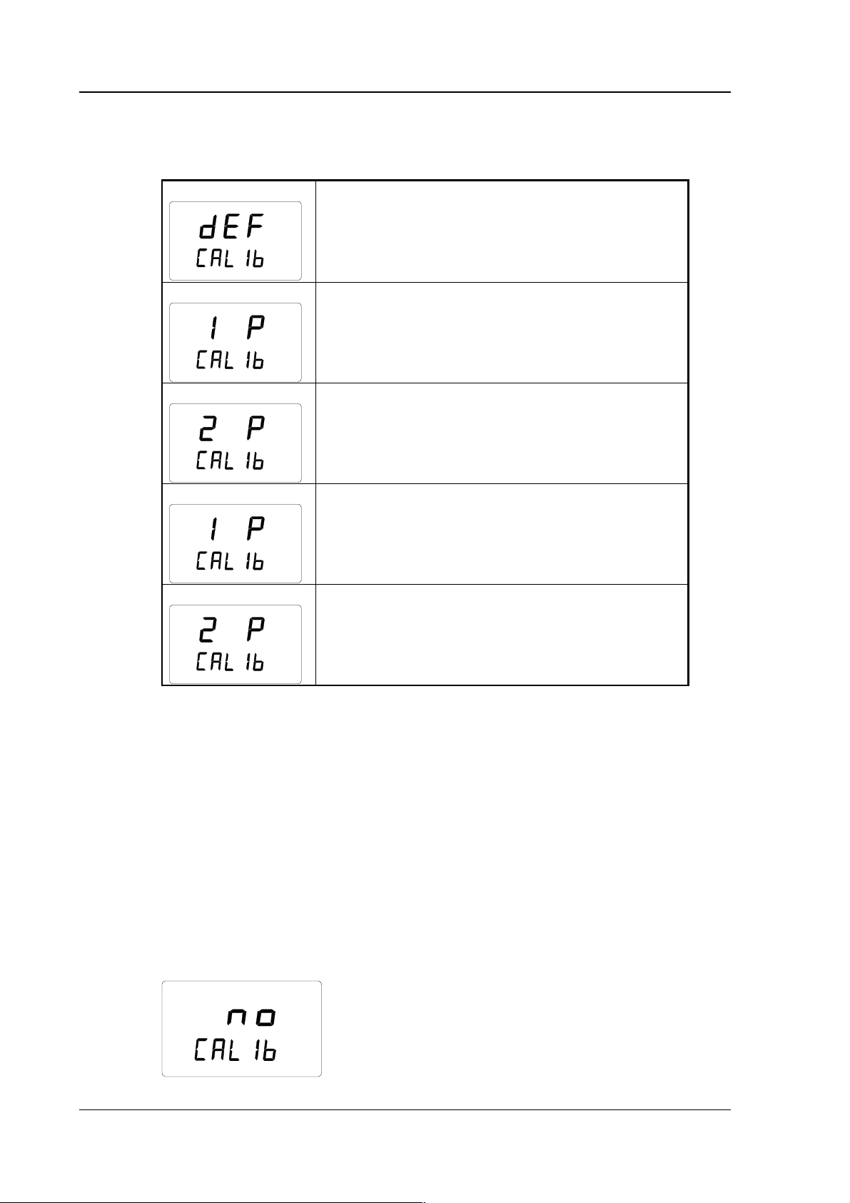
All selections are acknowledged with ENTER. In the following, you will find
a list of these calibration options.
RH
T
Default calibration restores the factory settings of
the humidity and temperature calibrations.
set
RH
One point humidity calibration; select this for
performing humidity calibration at one point. See
Chapter 5.3.1 for further details.
set
RH
Two point humidity calibration; select this for
performing humidity calibration at two points.
See Chapter 5.3.2 for further details.
set
T
One point temperature calibration; select this for
performing temperature calibration at one point.
See Chapter 5.3.3 for further details.
set
T
Two point temperature calibration; select this for
performing temperature calibration at two points.
See Chapter 5.3.4 for further details.
set
16
5.3.1 One point humidity calibration
In one point humidity calibration, one accurate humidity reference is
sufficient. However, note that after one point calibration, the humidity reading
is most accurate near the reference value. For a better accuracy over the whole
range, perform a two point calibration if possible.
Leave the reference instrument (HMK15 or HMK13B) and the probe at the
calibration site at least 30 minutes so that the probe temperature stabilizes to
the room temperature. Start the calibration by inserting the probe to the
reference humidity.
In setup mode, press ENTER repeatedly until the following is displayed:
set
Page 21
HMI41 AND HMP42
U323en-1.1 Operating Manual
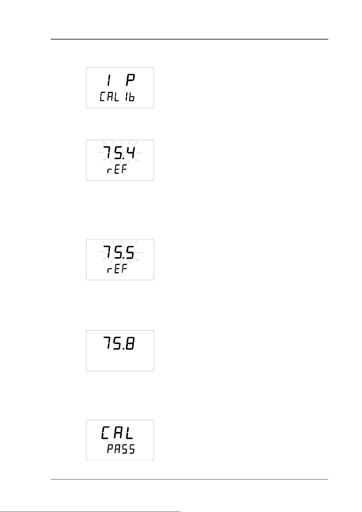
Then press MODE twice, and the following appears:
RH
set
Press ENTER to activate the one point calibration mode. A message similar to
the following appears with the first line blinking:
RH
set
%
The blinking number indicates the humidity reference value in the HMI41
memory. Check the salt chamber temperature, read the closest humidity value
in the calibration table and adjust the display with buttons ▲ and ▼ to
correspond to the value given in the table. For example, if the temperature in
the calibrator's NaCl salt chamber is 20.5 °C, adjust the value to 75.5 %RH:
RH
set
%
Each time the button is pressed, the value changes with 0.1 %. If you keep the
button pressed, the value changes in a faster mode. Press ENTER and the
HMI41 indicator shows the value that the probe is currently measuring,
displaying a message similar to the following:
RH %
Wait at least ten minutes for the reading to stabilize and press ENTER to
acknowledge the value. Press ENTER again to conclude the one point
calibration. If the calibration has been successful, the following message
appears:
17
Page 22
HMI41 AND HMP42
Operating Manual U323en-1.1
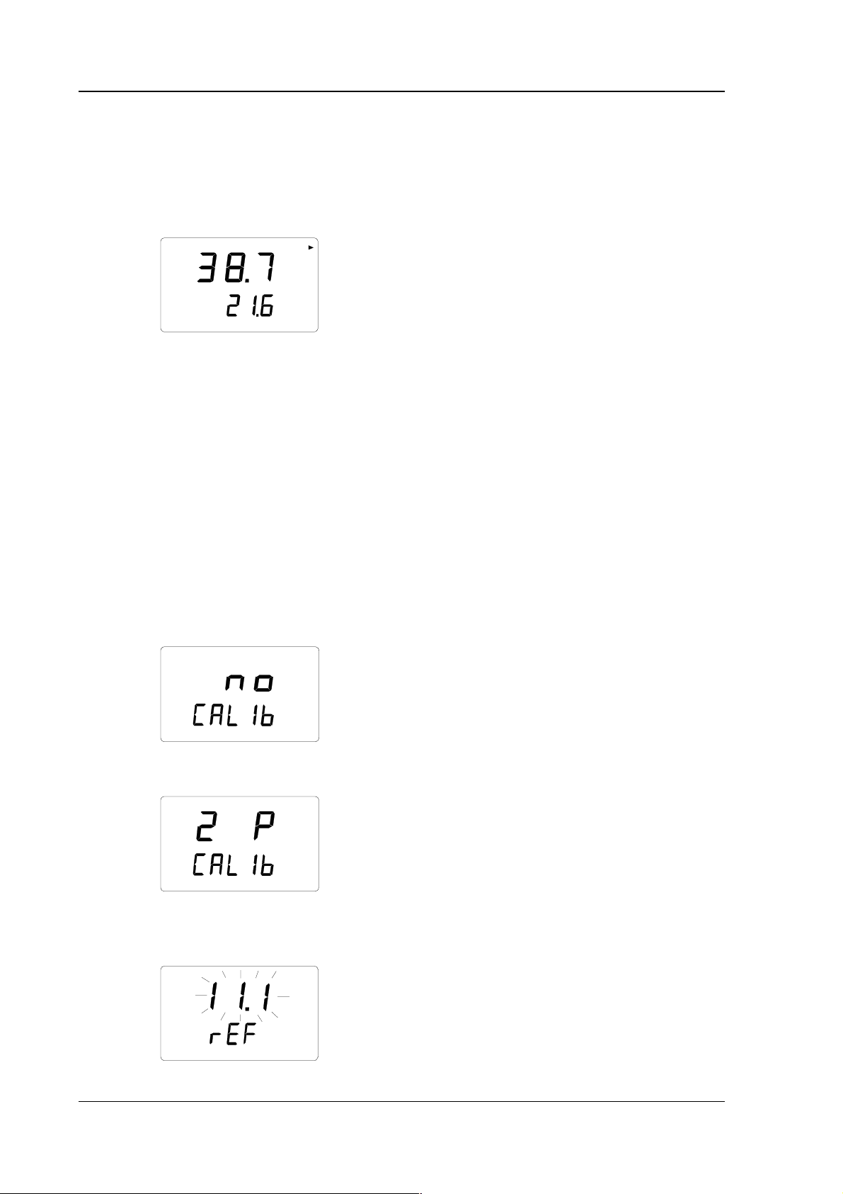
The correction data has now been calculated and stored in the HMI41 memory.
The HMI41 returns automatically to the selection of display units, and can be
turned off. When the indicator is used as a standard indicator and the
correction data differs from the factory settings, an arrow in the upper
righthand corner is displayed:
RH
T
%
°C
If the message “cal pass” does not appear (instead, some other text may
appear, e.g. “too close”, “err offst” or “err gain”), the correction has not been
stored in the memory. The error may be due to an incorrect reference value or
to measured values that are out of the range.
5.3.2 Two point humidity calibration
In two point humidity calibration, two accurate references (e.g. the HMK15 or
the HMK13B Calibrator) are needed. Leave the reference instrument and the
probe at the calibration site for at least 30 minutes so that the probe
temperature stabilizes to the room temperature.
Start the calibration by inserting the probe to the lower reference humidity. In
setup mode press ENTER repeatedly until the following is displayed:
18
set
Then press MODE three times, and the following appears:
RH
set
Press ENTER to activate the two point humidity calibration mode. A message
similar to the following appears with the first line blinking:
RH
set
%
Lo
Page 23

HMI41 AND HMP42
U323en-1.1 Operating Manual
The blinking number indicates the value of the lower humidity reference
stored in the HMI41 memory. Check the salt chamber temperature, read the
closest humidity value in the calibration table and adjust the display with
buttons ▲ and ▼ to correspond to the value given in the table. For example, if
the temperature of the LiCl salt chamber is 22 °C, adjust the value to
11.3 %RH:
RH
set
%
Lo
Press ENTER, and the HMI41 shows the value that the probe is currently
measuring, displaying a message similar to the following:
RH %
Lo
Wait at least ten minutes for the reading to stabilize and press ENTER to
acknowledge the value. Press ENTER again to conclude the lower point
calibration. A message similar to the following appears with the first line
blinking:
RH
%
set
Hi
The blinking number indicates the value of the higher humidity reference
stored in the HMI41 memory. Insert the probe to the higher reference
humidity. Check the salt chamber temperature, read the closest humidity value
in the calibration table and adjust the display with buttons ▲ and ▼ to
correspond to the value given in the table. For example, if the temperature in
the calibrator's NaCl salt chamber is 20.5 °C, adjust the value to 75.5 %RH:
RH
set
%
Press ENTER and the HMI41 indicator shows the value that the probe is
currently measuring, displaying a message similar to the following:
19
Page 24

HMI41 AND HMP42
Operating Manual U323en-1.1
RH %
Hi
Wait at least ten minutes for the reading to stabilize and press ENTER to
acknowledge the value. Press ENTER again to conclude the calibration. If the
calibration has been successful, the following message appears:
The correction data has now been calculated and stored in the HMI41 memory.
The HMI41 returns automatically to the selection of the display units, and can
be turned off. When the indicator is used as a standard indicator and the
correction data differs from the factory settings, an arrow in the upper
righthand corner is displayed:
RH
T
%
°C
If the message “cal pass” does not appear (instead, some other text may
appear, e.g. “too close”, “err offst” or “err gain”), the correction has not been
stored in the memory. The error may be due to an incorrect reference value or
to measured values that are out of the range.
5.3.3 One point temperature calibration
In one point temperature calibration, one accurate temperature reference is
sufficient.
Start the calibration by inserting the probe to the reference temperature.
In setup mode, press ENTER repeatedly until the following is displayed:
20
set
Then press MODE four times, and the following appears:
Page 25

HMI41 AND HMP42
U323en-1.1 Operating Manual
T
set
Press ENTER to activate the one point temperature calibration mode.
A message similar to the following appears with the first line blinking:
T°C
set
The blinking number indicates the temperature reference value stored in the
HMI41 memory. Check the actual temperature reference and change the
display with buttons ▲ and ▼ to correspond to the accurate value, for
example:
T°C
set
Press ENTER and the HMI41 indicator shows the value that the probe is
currently measuring, displaying a message similar to the following:
T°C
Wait at least ten minutes for the reading to stabilize and press ENTER to
acknowledge the value. Press ENTER again to conclude the calibration. If the
calibration has been succesful, the following message appears:
The correction data has now been calculated and stored in the HMI41 memory.
The HMI41 returns automatically to the selection of the display units, and can
be turned off. When the indicator is used as a standard indicator and the
correction data differs from the factory settings, an arrow in the upper
righthand corner is displayed:
21
Page 26

HMI41 AND HMP42
Operating Manual U323en-1.1
RH
T
%
°C
If the message “cal pass” does not appear (instead, some other text may
appear, e.g. “too close”, “err offst” or “err gain”), the correction has not been
stored in the memory. The error may be due to an incorrect reference value or
to measured values that are out of the range.
5.3.4 Two point temperature calibration
In two point temperature calibration, two accurate temperature references are
needed. Note that you must allow enough time for all instruments to stabilize
to the temperature equilibrium.
Start the calibration by inserting the probe to the lower reference temperature.
In setup mode, press ENTER repeatedly until the following is displayed:
set
Then press MODE five times, and the following appears:
T
set
Press ENTER to activate the two point temperature calibration mode. A
message similar to the following appears with the first line blinking:
T
set
°C
Lo
The blinking number indicates the value of the lower temperature reference
stored in the HMI41 memory. Insert the probe to the lower reference
temperature. Check the reference temperature and change the display with
buttons ▲ and ▼ to correspond to the accurate value, for example:
22
Page 27

HMI41 AND HMP42
U323en-1.1 Operating Manual
T
set
°C
Lo
Press ENTER and the HMI41 shows the value that the probe is currently
measuring, displaying a message similar to the following:
T
°C
Lo
Wait at least ten minutes for the reading to stabilize and press ENTER to
acknowledge the value. Press ENTER again to conclude the lower point
calibration. A message similar to the following appears with the first line
blinking:
T
°C
set
Hi
The blinking number indicates the value of the higher temperature reference
stored in the HMI41 memory. Insert the probe to the higher reference
temperature. Check the reference temperature and change the display with
buttons ▲ and ▼ to correspond to the accurate value, for example:
T
set
°C
Hi
Press ENTER and the HMI41 shows the value that the probe is currently
measuring, displaying a message similar to the following:
T°C
Hi
Wait at least ten minutes for the reading to stabilize and press ENTER to
acknowledge the value. Press ENTER again to conclude the calibration. If the
calibration has been successful, the following message appears:
23
Page 28

HMI41 AND HMP42
Operating Manual U323en-1.1
The correction data has now been calculated and stored in the HMI41 memory.
The HMI41 returns automatically to the selection of the display units, and can
be turned off. When the indicator is used as a standard indicator and the
correction data differs from the factory settings, an arrow in the upper
righthand corner is displayed:
RH
T
%
°C
If the message “cal pass” does not appear (instead, some other text may
appear, e.g. “too close”, “err offst” or “err gain”), the correction has not been
stored in the memory. The error may be due to an incorrect reference value or
to measured values that are out of the range.
24
Page 29

HMI41 AND HMP42
U323en-1.1 Operating Manual
6. HMI41 AND DATA COLLECTING
The HMI41 indicator can also be used for collecting the measurement data.
The data is stored in the indicator's non-volatile memory which means that it
is not lost when the indicator is turned off. P lease, note also that th e automatic
power-off function is not active during data collecting even if previously
selected (see Chapter 8.3). When the data collecting has ended, the automatic
power-off function becomes active again.
6.1 Entering the data collecting mode
To enter the data collecting mode, turn the indicator on with the ON/OFF
button and the following appears for a couple of seconds:
RH
Td
T
P
set min max hyst hold Lo bat Hi
Release the ON/OFF button and press immediately the button HOLD. The
%
°C °F
°C
°F
Pahg/m
software version and the probe type indication appear, after which the display
changes automatically to show the battery charge:
Hi
Within a couple of seconds the text REC AUTO appears on the display; release
bat
the HOLD button.
This is the main display of the data collecting mode. With the button MODE
you can enter the REC CATCH mode (manual data collecting, see Chapter 6.2)
and by pressing MODE again, the REC READ mode (reading the measurement
results, see Chapter 6.5). By pressing ENTER, you can set the measurement
duration and by pressing ENTER again, the measurement interval (Chapters
6.3 and 6.4). By pressing HOLD, you can always return to the previous
display.
25
Page 30

HMI41 AND HMP42
Operating Manual U323en-1.1
6.2 Manual data collecting
For manual data collecting, press the button MODE and the following appears:
Press ENTER and a text similar to the following appears:
RH
T°C
set
%
The probe is now taking measurements and you can store the readings at
appropriate intervals by pressing the button HOLD. The sequence number of
the reading in the indicator memory appears for a couple of seconds:
The indicator returns automatically to show the readings. You can store 199
measurement readings in the indicator memory (numbers 1 - 199). In
automatic data collecting, you can store 200 readings (0 - 199). Data
collecting is ended by turning the indicator off. The readings can be read in
the REC READ mode (see Chapter 6.5).
26
Page 31

HMI41 AND HMP42
U323en-1.1 Operating Manual
6.3 Setting the measurement duration
Turn the indicator on with the ON/OFF button, press immediately the button
HOLD and keep it pressed until the text REC AUTO appears on the display.
Press ENTER and a text similar to the following on the display:
In this mode, you can set the time between the first and the last measurement
bat
(previously set duration)
stored, e.g. 30 minutes or 3 days. When entering this mode, previously set
duration time appears on the display. If the previously set duration time is too
long for the current battery charge, the longest calculated duration time
possible for this battery charge appears instead. This is also indicated with the
text 'MAX'. The duration of the measurement can be set from 15 minutes to 7
days. The batteries last for 7 days during data collecting provided that they are
of the same type as those delivered with the indicator.
Set the duration with buttons ▲ and ▼. The duration time can be selected in
steps according to the following:
• 15 min; 30 min
• 1 - 6 h: each pressing = 1 h
• 12 h
• 1 - 7 d: each pressing = 1 d
If the duration selected is too long for the current battery charge, the text 'BAT'
appears. Select a shorter duration time.
By pressing ENTER, the indicator goes on to the setting of the measurement
interval.
6.4 Setting the measurement interval
min
In this mode, you can set the time that you wish to pass between two
(previously set interval)
measurements being stored, e.g. 5 minutes or 2 hours. When entering this
mode, previously set interval appears on the display. If the previously set
measurement interval is too short for the current memory capacity of the
indicator, the shortest calculated measurement interval appears instead. This is
also indicated with the text 'MIN'.
27
Page 32

HMI41 AND HMP42
Operating Manual U323en-1.1
Select the interval with buttons ▲ and ▼. The measurement interval can be
selected in steps according to the following:
• 1 - 5 min: each pressing = 1 minute
• 10 min; 15 min; 30 min
• 1 - 6 h: each pressing = 1 hour
• 12 h
The text 'LO' on the display indicates that there is not enough memory for the
chosen interval; select a longer interval. By pressing ENTER, a text similar to
the following appears:
RH
%
T°C
set
This is the measurement mode with the dat a collecting feature activ ated. It can
be distinguished from the normal measurement mode by the text 'SET' on the
lower lefthand corner of the display. The readings on the display are updated
once a minute, and the display is dim except during this updating in order
to minimize the consumption. If the indicator is turned off, the measurements
stored so far remain in the memory and they can be read by turning the
indicator on in the REC READ mode (see section 6.5).
You can end data collecting by pressing ON/OFF.
6.5 Reading the measurement results
The measurement results can be read in the REC READ mode. This mode can be
entered from the
REC AUTO mode by pressing twice the button MODE. The
following appears:
28
Press ENTER, and a text similar to the following appears on the display:
RH
T°C
Numbers on the first line indicate the reading of the quantity in question (in
%
this example, RH). The number on the left of the second line (in this example
Page 33

HMI41 AND HMP42
U323en-1.1 Operating Manual
number 0.) is the sequence number of the m easurement. This number helps to
estimate the time of the measurement during automatic data collecting
provided that the starting time and the measurement interval are known.
Numbers located on the right on the second line indicate the temperature
reading measured simultaneously with the reading on the first line; if you wish
to see the decimals, press ENTER. The reading appears on the display with
one decimal:
RH
T°C
In a couple of minutes the indicator returns to the previous display.
By pressing MODE, you can change the quantity on the first line:
d
T
T
By pressing ENTER (with any quantity on the first line), an arrow appears on
%
°C
°C
the upper righthand corner of the display:
RH
T°C
%
By pressing HOLD while the arrow is displayed, you can scroll the
measurement results (note that the sequence number changes):
RH
T°C
HOLD:
RH
T°C
If the buttons are pressed continuously, numbers change in a faster rate.
%
%
etc.
29
Page 34

HMI41 AND HMP42
Operating Manual U323en-1.1
6.5.1 MIN and MAX in data collecting REC READ mode When the data collecting REC READ mode has been activated, the HOLD
button brings four different modes on the display: MIN HI, MAX HI, MIN LO and
MAX LO. These modes indicate the maximum and minimum readings measured
for the quantities on the display. HI and LO tell you whether the reading
observed is the one on the first line (HI) or the one on the second line (LO).
MIN and MAX indicate whether the reading on the display is the minimum or
the maximum value. In other words, if the text is MIN HI it means that you are
now observing the minimum reading of the quantity on the first line.
By pressing HOLD repeatedly you can change from one display mode to
another, and by pressing MODE you can change the quantity on the first line.
In all these modes, the decimals of the second line reading are shown by
keeping the button ENTER pressed down.
Examples:
RH
%
RH
%
ENTER
T°C
min
Hi
returns automatically
T°C
min
Hi
(minimum reading of the 1st line quantity) (decimals of the 2nd line)
HOLD
RH
%
RH
%
ENTER
T°C
max Hi
returns automatically
(maximum reading of the 1st line quantity)
T°C
max
Hi
(decimals of the 2nd line)
HOLD
RH
%
RH
%
ENTER
T°C
min
Lo
returns automatically
(minimum reading of the 2nd line quantity)
T°C
min
Lo
(decimals of the 2nd line)
HOLD
30
RH
%
ENTER
T°C
max
(maximum reading of the 2nd line reading)
Lo
returns automatically
RH
T°C
max
%
Lo
(decimals of the 2nd line)
Page 35

HMI41 AND HMP42
U323en-1.1 Operating Manual
7. TRANSFERRING THE STORED READINGS TO A PC
The readings that have been stored in the HMI41 memory manually or
automatically in the data collecting mode, can be transferred to a computer
and then printed if desired. In order to do this, connect a serial connection
cable (order code 19446ZZ) to the appropriate connectors:
connect the
serial cable
to the EXT
connector
Figure 7.1 Connecting the cable
7.1 Giving the communication parameters
Give the communication parameters when using this terminal session for the
first time; save them for future use. See instructions in the following tables.
Table 7.1.1 Giving parameters in Windows 3.1
MENU DESCRIPTION
PROGRAM MANAGER
ò
ACCESSORIES
ò
TERMINAL
ò
Settings
ò
Communications
ò
File
ò
Save as
double click
double click
click
click and give parameters
(see figure 7.1.1 next page);
click OK
click and save settings: type
the name of the file (e.g.
HMI41) and click OK
Turn the HMI41 on and follow the instructions in Ch. 7.2
31
Page 36

HMI41 AND HMP42
Operating Manual U323en-1.1
NOTE: select the
connector
according to
your computer.
Select the
connector first
and then other
Figure 7.1.1 Giving the communication parameters in Windows 3.1
32
Page 37

HMI41 AND HMP42
U323en-1.1 Operating Manual
Table 7.1.2 Giving parameters in Windows 95 and Windows NT
WINDOWS 95 WINDOWS NT
MENU WHAT TO DO MENU WHAT TO DO
Start Start
ò
move the cursor to:
ò
move the cursor to:
Programs Programs
ò
move the cursor to:
ò
move the cursor to:
Accessories Accessories
ò
move the cursor to:
ò
move the cursor to:
HyperTerminal
ò
Hypertrm
òò
Connection
Description
ò
Phone Number
òò
click
move the cursor to:
double click
type the name of the
connection (e.g.
HMI41) in the
appropriate field
and select an icon if
available; click OK.
move the cursor to
the field CONNECT
USING
and select
'direct to COM x'
(x = serial port
available); click OK
HyperTerminal
ò
Hyperterminal
Connection
Description
Connect to
move the cursor to:
click
type the name of the
connection (e.g.
HMI41) in the
appropriate field and
select an icon if
available; click OK.
move the cursor to
the field CONNECT
and select
USING
'COM x' (x = serial
port available); click
OK
select parameters
COM x properties
according to the
COM x properties
screen in figure
7.1.2; click OK
Turn the HMI41 on and follow the instructions in Chapter 7.2
select parameters
according to the
screen in figure
7.1.2; click OK
33
Page 38

HMI41 AND HMP42
Operating Manual U323en-1.1
Figure 7.1.2 Selecting the parameters in Windows 95 and NT
7.2 Transferring the data
When you have given the communication parameters, you can start
transferring the data from the HMI41. Store the parameters for future use.
To start transferring the data, make sure that the HMI41 is connected to a
serial port of your computer and that the terminal session is open. Turn the
HMI41 on and a text similar to the following appears:
HMI41 / 2.01
>
7.2.1 PLAY Transferring the data
To transfer the data on your PC, type PLAY and press ENTER; an example of
outputting automatically collected data:
>play
Reading Log... OK
data hh:mm:ss RH T Td
0 00:00:00 12.54 21.53 -8.48
1 00:01:00 12.10 21.23 -9.16
2 00:02:00 12.18 21.18 -9.12
3 00:03:00 12.12 21.15 -9.21
4 00:04:00 12.16 21.14 -9.18
5 00:05:00 12.09 21.12 -9.27
6 00:06:00 12.09 21.09 -9.28
>
34
Page 39

HMI41 AND HMP42
U323en-1.1 Operating Manual
An example of outputting manually collected data:
>play
Reading Log... OK
data RH T Td
12.54 21.53 -8.48
1 12.10 21.23 -9.16
2 12.18 21.18 -9.12
3 12.12 21.15 -9.21
4 12.16 21.14 -9.18
5 12.09 21.12 -9.27
6 12.09 21.09 -9.28
>
If you know the starting time of the automatic data collecting, you can enter it
with the command and get an output showing the actual time of measurement.
For example:
>play 15:05
Reading Log... OK
data hh:mm:ss RH T Td
0 15:05:00 8.52 23.69 -11.70
1 15:06:00 9.58 23.66 -10.26
2 15:07:00 9.60 23.50 -10.35
3 15:08:00 9.61 23.30 -10.48
4 15:09:00 9.65 23.25 -10.47
5 15:10:00 11.22 23.41 -8.44
6 15:11:00 9.93 23.30 -10.08
7 15:12:00 9.92 23.22 -10.15
>
7.2.2 CPLAY Setting characters between decimals and fields
With the CPLAY command, you can select what you want to appear between
decimals and various fields. An example:
>cplay
Desimal separator : .
Field separator : TAB
example:
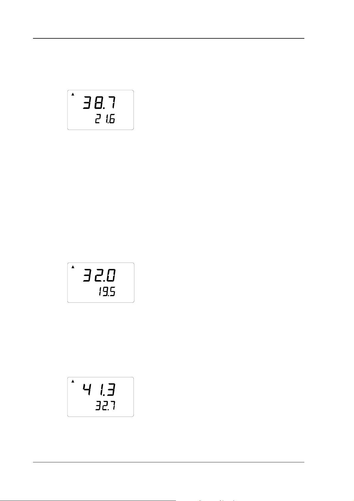
1 01:00:00 38.72 21.61 7.01
>
To change the output, type CPLAY, then the character you wish to appear
between decimals, then the character you wish to use between fields and then
<cr>. An example:
>cplay , <cr>
Desimal separator : ,
Field separator : TAB
example:
1 01:00:00 38,72 21,61 7,01
>
35
Page 40

HMI41 AND HMP42
Operating Manual U323en-1.1
7.2.3 HELP Outputting all available commands and their contents
If you wish to see which commands are available, type HELP and press
ENTER. The following list appears:
>help
Available commands :
HELP ? PLAY CPLAY
Type HELP <command_name> for more help
>
To see the contents of each command, type HELP, command name (e.g. PLAY)
and press ENTER; this brings an explanation of the command and its usage on
the display:
>help play
Command : PLAY
Purpose : Send recordings from memory to serial port
Usage : PLAY hh:mm <cr>, hh:mm = rec starting time (optional)
if command is used without parameters it uses default setting
>
7.3.4 ? Outputting the HMI41 settings
If you need to know which parameters and settings are currently stored in your
HMI41 indicator, type ? and press ENTER:
>?
HMI41 / 2.01
Serial number : A0000000
Output units : metric
Baud P D S : 4800 E 7 1 FDX
Pressure : 1013.25
Auto Off : 5
Probe : 2
Start-up mode : 1
4.th variable : none
>
To exit the terminal session, move the cursor to FILE menu and select EXIT.
Confirm that you wish to quit and then select whether you wish to store the
parameters of this session for future use or not (SAVE - YES/NO).
36
Page 41

HMI41 AND HMP42
U323en-1.1 Operating Manual
8. SETUP PROCEDURE
The indicator settings can be changed in the SETUP mode. Note that manual
setup procedure is necessary if some of the factory settings have to be changed
and if the indicator or the probe does not have letters ID in the instrument
label.
The factory settings of the HMI41 are the following:
• display units: 0 (metric)
• automatic power-off: 5 minutes
• display quantities: 0 (= RH, T, Td)
• pressure: 1013.25 hPa (1 hPa = 1 mbar)
(for wet bulb temperature and mixing ratio calculations)
• probe type AUT (or 1, see below)
• start 1
Indicators marked with letters ID have the automatic probe recognition as
default (AUT PROBE) and previous versions the probe type 1. If the indicator
does not recognize the probe type automatically, set th e type manually to
2 when using the HMP42. Note also that the HMP42 probe cannot be used
with the HMI41 unless the software version is 1.02 or greater. To check the
version, turn the HMI41 on with the ON/OFF button. The version appears on
the display in a couple of seconds if it is 1.02 or greater. If it does not appear,
contact Vaisala or a Vaisala representative for furt her informati on.
8.1 Entering the setup mode
For entering the setup mode, first press the ON/OFF button and the following
appears:
RH
Td
T
P
set min max hyst hold Lo bat Hi
%
°C °F
°C
°F
Pahg/m
Then release the ON/OFF button and within 1 - 2 seconds press simultaneously both ENTER and MODE buttons until the following text appears on the
display:
37
Page 42

HMI41 AND HMP42
Operating Manual U323en-1.1
After a few seconds, the text changes automatically to show the following:
°C
set
You can scroll the setup menu by pressing ENTER.
8.2 Selecting the display units
°C
set
You can now select the display units with buttons ▲ (number up) or ▼
(number down). Choose 0 for metric units or 1 for non-metric units (see Table
8.2). The temperature unit on the display changes accordingly. If you do not
wish to change any other settings, press the ON/OFF button. If you wish to
change some other settings, press ENTER; the display changes to show the
setting of the automatic power-off function.
Table 8.2 Metric and non-metric units
quantity metric non-metric
RH %RH %RH
T
Td
ag/m3gr/ft
°C °F
°C °F
3
x g/kg gr/lb
Tw
°C °F
38
Page 43

HMI41 AND HMP42
U323en-1.1 Operating Manual
8.3 Setting the automatic power-off function
set
The number (or text NO) on the first line of the display indicates in minutes
(1...60) the time that the HMI41 stays on before it automatically turns itself
off if no buttons are pressed. The number is changed with buttons ▲ (number
up) and ▼ (number down). If NO is chosen, the automatic power-off function
is not activated. If you do not wish to change any other settings, press the
ON/OFF button. If you wish to change some other settings, press ENTER; the
display changes to show the selection of the display quantities.
8.4 Selecting the display quantities
set
The HMI41 displays relative humidity, temperature and dewpoint temperature
readings. In addition to these, one of the following quantities can be chosen:
absolute humidity, wet bulb temperature and mixing ratio. The number on the
display indicates the following quantities:
0 = RH, T, Td
1 = RH, T, Td, abs
2 = RH, T, Td, Tw
3 = RH, T, Td, x
The number is changed with buttons ▲ (number up) and ▼ (number down). If
you do not wish to change other settings, press the ON/OFF button. If you
wish to change other settings, press ENTER; the display changes to show the
setting of the pressure for mixing ratio and wet bulb temperature calculations.
39
Page 44

HMI41 AND HMP42
Operating Manual U323en-1.1
8.5 Setting the pressure for mixing ratio and wet bulb temperature calculations
PPah
set
The pressure is changed (in steps of 0.25 hPa) with buttons ▲ (number up)
and ▼ (number down). Acknowledge the pressure setting with ENTER and a
text similar to the following appears:
set
or
Indicators marked with letters ID have the automatic probe recognition as
default (AUT PROBE) and previous versions the probe type 1. If the indicator
does not recognize the probe type automatically, set the type manually to 2
(see below) when using the HMP42.
8.6 Selecting the probe type
set
Change the setting with buttons ▲ (number up) and ▼ (number down). You
have now completed the setup procedure; turn your indicator off.
set
NOTE
40
The HMI41 setup contains further settings (start, baud,
seri and calib) that appear after probe type setting when
pressing ENTER. Start setting is changed only when
using the HMP44/44L probes (START 5, see the HM44
Operating Manual). For calib, see Chapter 5. Other
settings are meant for the HMI41 used as a field
calibrator for other Vaisala humidity transmitters. It is
recommended that these settings are not changed.
Page 45

HMI41 AND HMP42
U323en-1.1 Operating Manual
9. MAINTENANCE
9.1 Changing the filter and the sensor head set
For changing the filter, unscrew the steel grid, remove the membrane filter
(see Figure 9.1) and replace it with a new one. A set of membrane filters is
delivered with the probe. Screw the steel grid back on.
NOTE
Do not use the probe without the membrane filter in
order not to damage the sensors.
Figure 9.1 Changing the filter
If the steel grid looks dirty, remove it and clean the holes e.g. with a needle.
It is recommended that the sensor head set is changed by Vaisala authorized
maintenance personnel only. However, if for some reason it is necessary to do
this yourself, be careful not to break the sensor. Unscrew the sensor head set
and mount a new set in its place. Handle the sensor head with care. Calibrate
the probe using a two-point calibration procedure (see section 5.3.2).
9.2 Chemical tolerances of the HUMICAPMINI sensor
Long-term exposure of the HUMICAPMINI sensor to certain chemicals and
gases may affect the characteristics of the sensor and shorten its life. The
following table gives the recommended maximum ambient concentrations of
some chemicals:
ppm (typ.)
Organic solvents 1000...10 000
Aggressive chemicals (e.g. strong acids
1...10
such as SO2, H2SO4, H2S, HCl, Cl2, etc.)
Weak acids 100...1000
Bases 10 000...100 000
Detailed information on allowed concentrations can be requested from Vaisala
representatives.
41
Page 46

HMI41 AND HMP42
Operating Manual U323en-1.1
9.3 Spare parts and accessories
Order code Description
19809HM Rubber sleeve set (10 pcs)
HM37067 Calibration adapter
19858HM Membrane filter set, 5 pcs (AISI 316/PTFE)
19867HM Steel grid
HM27104 Carrying bag for HMI41 and HMP42
HM36959 Trimming screw wrench set 1.5 mm / 2.5 mm
HMP42P235SP Sensor head set: RH and T sensors, filters and installation
accessories
HMP41 RH & T probe; for fixed mounting
HMP42 RH & T probe; for tight places
HMP44/L RH & T probe; for measurements in structures
HMP45 RH & T probe; cable model
HMP46 RH & T probe; cable model, for dirty or hot processes
19446ZZ S erial interface cable for HMI41
19116ZZ C alibration cable (for HMD/W60/70, HMP140 series)
19164ZZ C alibration cable (for HMP230 series)
19165ZZ C alibration cable (for HMD/W20/30, HMP130 series)
HMK15 Humidity Calibrator
HMK13B Humidity Calibrator
42
Page 47

HMI41 AND HMP42
U323en-1.1 Operating Manual
10. IN CASE OF ERROR
The HMI41 goes through a continuous self-diagnostic procedure. If any
problems occur, it displays the corresponding error message:
where nn = the number indicating the error
Whenever you come across an error message or your indicator does not
function as it should, first check that the probe is correctly connected. Then
check that the filter and the steel grid are clean.
10.1 Trouble shooting
In the following, a short list for trouble shooting:
PROBLEM: WHAT TO DO:
the display is blank
the display is dim - during automatic data collecting, the display is dim
the readings seem to
be wrong
- check the batteries (see Chapters 3.1 and 9.1)
- if the batteries are ok, contact Vaisala or a Vaisala
representative
except when the readings are updated (once in a
minute)
- allow enough time for the probe to stabilize to
the ambient temperature
- check that the probe is correctly connected to the
indicator
- check that the steel grid and the membrane filter are
clean
- make sure that the measurement point is clean and
that there is no condensated water
- check that the settings are correct (see
Chapter 10.2)
you have accidentally
changed some settings
- enter the setup mode, select the setting with
ENTER and change it with buttons ▲ or ▼ (see
table on the next page). The pressure setting has to
be acknowledged with ENTER.
43
Page 48

HMI41 AND HMP42
Operating Manual U323en-1.1
10.2 Checking the settings
If these are in order, turn the HMI41 on and enter the setup mode (see Chapter
8). Make sure that the following settings are correct:
setting correct value
probe
start (*)
baud
seri
calib
AUT or 2 (with HMP42)
1
4.8
E.7.1
def (**)
(*) values 2, 3 and 4 are for calibration cables
(**) when the calib setting is entered, the value is always “no”; factory
settings for calibration correction data can be returned by selecting “def”
If the settings are not correct, change them: in the setup mode, select the
setting with ENTER, change it with buttons ▲ or ▼ and acknowledge with
ENTER. If the error message still appears, write it down and contact Vaisala
or a Vaisala representative for further instructions.
44
Page 49

HMI41 AND HMP42
U323en-1.1 Operating Manual
11. TECHNICAL DATA
11.1 HMI41 indicator
Maximum measurement error
caused by the indicator at 20 °C
(for system accuracy, see probes’ technical specifications)
humidity +0.1 %RH
temperature +0.1 °C
Calculated variables dewpoint temperature, absolute
humidity, wet bulb temperature,
mixing ratio
Resolution 0.1 %RH; 0.1 °C
Power supply 4 batteries, type AA (IEC LR6)
Battery operation time 72 h continuous use
Operating humidity range 0...100 %RH non-condensing
Operating temperature -20...+60 °C
Storage temperature -40...+70 °C
Display two line LCD
Housing material ABS plastic
Housing classification IP 53 (with connectors blocked)
Connector type modular connector
Weight (incl. batteries) 300 g
45
Page 50

HMI41 AND HMP42
Operating Manual U323en-1.1
11.2 HMP42 probe
11.2.1 Relative humidity
Measurement range 0...100 %RH non-condensing
Accuracy (at +20 °C)
when calibrated against
salt solutions (ASTM E104-85): ±2 %RH (0...90 %RH)
±3 %RH (90...100 %RH)
Temperature dependence
of electronics ±0.05 %RH/ °C
Typical long-term stability better than 1 %RH per year
Response time (90%) at 20 °C
in still air with 30 s
Humidity sensor HUMICAP®MINI
11.2.2 Temperature
Measurement range
(sensor head) -40...+100 °C
Accuracy at +20 °C ±0.2 °C
Accuracy:
0.6
0.4
0.2
0
-0.2
-0.4
-0.6
-40
-20
0
20
40
60 80
100
°C
Temperature sensor Pt 100 (IEC 751 1/3 Class B)
46
Page 51

HMI41 AND HMP42
U323en-1.1 Operating Manual
11.2.3 General
Cable length 1500 mm; extended spiral cable
Connector type modular connector
Operating temperature range
for electronics -20...+60 °C
Storage temperature range -40...+100 °C
Housing material ABS plastic
Housing classification (electronics) IP65 (NEMA 4)
Sensor protection steel grid with membrane filter
Weight 200 g
Dimensions (in mm):
38
ø4
V
ø18.5
bottom
view
235
13
ø21
30
13
106
47
Page 52

HMI41 AND HMP42
Operating Manual U323en-1.1
11.4 Accuracy of the calculated quantities
Dewpoint temperature, mixing ratio, absolute humidity and wet bulb temperature are calculated from the measured relative humidity and temperature
values. The accuracy of the calculated quantities depends on the calibration of
the probe and on performing the measurement correctly. In tables below the
accuracies of the measured values are ±2 %RH and ±0.2°C.
11.4.1 Accuracies in metric units
Accuracy of dewpoint temperature (°C)
RH/%
10 20 30 40 50 60 70 80 90 100
T/°C
-40
-20
20
40
60
80
100
120
140
160
1.82 1.00 0.74 0.61 0.53 0.48 0.44 0.42 - -
2.09 1.14 0.83 0.68 0.59 0.53 0.49 0.45 - -
2.51 1.37 1.00 0.81 0.70 0.63 0.57 0.53 0.50 0.48
0
2.87 1.56 1.13 0.92 0.79 0.70 0.64 0.59 0.55 0.53
3.24 1.76 1.27 1.03 0.88 0.78 0.71 0.65 0.61 0.58
3.60 1.96 1.42 1.14 0.97 0.86 0.78 0.72 0.67 0.64
4.01 2.18 1.58 1.27 1.08 0.95 0.86 0.79 0.74 0.70
4.42 2.41 1.74 1.40 1.19 1.05 0.95 0.87 0.81 0.76
4.86 2.66 1.92 1.54 1.31 1.16 1.04 0.96 0.89 0.84
5.31 2.91 2.10 1.69 1.44 1.27 1.14 1.05 0.97 0.91
5.80 3.18 2.30 1.85 1.57 1.38 1.24 1.14 1.06 0.99
T/°C
Accuracy of mixing ratio (g/kg) with
ambient pressure of 1013.25 mbar
RH/%
10 20 30 40 50 60 70 80 90 100
-40
-20
100
120
140
160
0.002 0.002 0.002 0.002 0.003 0.003 0.003 0.003 - -
0.014 0.015 0.017 0.018 0.019 0.020 0.022 0.023 - -
0.08 0.09 0.09 0.10 0.10 0.11 0.12 0.12 0.13 0.13
0
20
40
60
80
0.31 0.33 0.35 0.37 0.39 0.41 0.43 0.45 0.47 0.49
0.97 1.03 1.10 1.17 1.24 1.31 1.38 1.46 1.54 1.62
2.70 2.94 3.46 3.76 3.72 4.08 4.42 4.79 5.19 5.63
6.78 7.80 9.00 10. 4 12.2 14.3 16.9 20.2 24.4 29.7
16.4 21.6 29.2 41.3 62.0 101 190 462 - -
41.275.7176-------
- ---------
- ---------
48
Page 53

HMI41 AND HMP42
U323en-1.1 Operating Manual
Accuracy of absolute humidity (g/m3 )
RH/%
10 20 30 40 50 60 70 80 90 100
T/°C
-40
-20
100
120
140
160
0.003 0.003 0.003 0.003 0.004 0.004 0.004 0.005 - -
0.020 0.021 0.023 0.025 0.026 0.028 0.029 0.031 - -
0.10 0.11 0.12 0.13 0.13 0.14 0.15 0.15 0.16 0.17
0
20
40
60
80
0.37 0.39 0.41 0.43 0.45 0.47 0.49 0.51 0.53 0.55
1.08 1.13 1.18 1.24 1.29 1.34 1.39 1.44 1.49 1.54
2.73 2.84 2.95 3.07 3.18 3.29 3.40 3.52 3.63 3.74
6.08 6.30 6.51 6.73 6.95 7.17 7.39 7.61 7.83 8.05
12.2 12.6 13.0 13.4 13.8 14.2 14.6 15.0 15.3 15.7
22.6 23.3 23.9 24.6 25.2 25.8 26.5 27.1 27.8 28.4
39.1 40.0 41.0 42.0 43.0 44.0 45.0 45.9 46.9 47.9
63.5 64.9 66.4 67.8 69.2 70.7 72.1 73.5 75.0 76.4
Accuracy of wet bulb temperature (°C)
RH/%
10 20 30 40 50 60 70 80 90 100
T/°C
-40
-20
20
40
60
80
100
120
140
160
0.20 0.20 0.20 0.20 0.20 0.20 0.20 0.20 - -
0.21 0.21 0.21 0.21 0.22 0.22 0.22 0.22 - -
0.27 0.28 0.28 0.29 0.29 0.29 0.30 0.30 0.31 0.31
0
0.45 0.45 0.45 0.44 0.44 0.44 0.43 0.43 0.42 0.42
0.84 0.77 0.72 0.67 0.64 0.61 0.58 0.56 0.54 0.52
1.45 1.20 1.03 0.91 0.83 0.76 0.71 0.67 0.63 0.61
2.24 1.64 1.32 1.13 0.99 0.90 0.82 0.76 0.72 0.68
3.06 2.04 1.58 1.31 1.14 1.01 0.92 0.85 0.80 0.75
3.86 2.41 1.81 1.48 1.28 1.13 1.03 0.95 0.88 0.83
4.57 2.73 2.03 1.65 1.41 1.25 1.13 1.04 0.97 0.91
5.23 3.04 2.24 1.81 1.55 1.36 1.23 1.13 1.05 0.98
11.4.2 Accuracies in non-metric units
Accuracy of dewpoint temperature (°F)
RH/%
10 20 30 40 50 60 70 80 90 100
T/°F
-40
-4
32
68
104
140
176
212
248
284
320
3.28 1.80 1.33 1.10 0.96 0.86 0.80 0.75 - -
3.76 2.05 1.50 1.22 1.06 0.95 0.88 0.82 - -
4.52 2.47 1.80 1.46 1.26 1.13 1.03 0.96 0.90 0.86
5.16 2.81 2.04 1.65 1.42 1.26 1.15 1.06 1.00 0.95
5.83 3.16 2.29 1.85 1.58 1.40 1.27 1.18 1.10 1.04
6.48 3.53 2.55 2.05 1.75 1.55 1.41 1.30 1.21 1.14
7.22 3.93 2.84 2.28 1.95 1.72 1.55 1.43 1.33 1.26
7.95 4.34 3.13 2.52 2.15 1.89 1.71 1.57 1.46 1.38
8.75 4.78 3.45 2.77 2.36 2.08 1.88 1.72 1.60 1.50
9.56 5.24 3.78 3.04 2.59 2.28 2.05 1.88 1.75 1.64
10.4 5.73 4.14 3.33 2.83 2.49 2.24 2.05 1.90 1.79
49
Page 54

HMI41 AND HMP42
Operating Manual U323en-1.1
Accuracy of mixing ratio (gr/lb)
with ambient pressure of 1013.25 mbar
RH/%
10 20 30 40 50 60 70 80 90 100
T/°F
-40
104
140
176
212
248
284
320
0.013 0.014 0.015 0.016 0.018 0.019 0.020 0.021 - -
0.099 0.108 0.116 0.125 0.134 0.142 0.151 0.159 - -
-4
32
68
0.57 0.61 0.65 0.69 0.73 0.77 0.81 0.85 0.89 0.93
2.17 2.31 2.44 2.58 2.72 2.87 3.01 3.15 3.30 3.44
6.85 7.31 7.77 8.25 8.74 9.25 9.77 10.3 10.9 11.4
18.9 20.6 22.3 24.2 26.3 28.5 30.9 33.5 36.4 39.4
47.5 54.6 63.0 73.1 85.2 100 118 141 170 208
115 151 205 289 434 709 1329 3237 - 288 530 1235 - - -----
- ---------
- ---------
T/°F
T/°F
Accuracy of absolute humidity (gr/ft3 )
RH/%
10 20 30 40 50 60 70 80 90 100
-40
104
140
176
212
248
284
320
0.001 0.001 0.001 0.002 0.002 0.002 0.002 0.002 - -
0.009 0.009 0.010 0.011 0.011 0.012 0.013 0.014 - -
-4
0.046 0.049 0.052 0.055 0.058 0.060 0.063 0.066 0.069 0.072
32
68
0.16 0.17 0.18 0.19 0.20 0.21 0.21 0.22 0.23 0.24
0.47 0.49 0.52 0.54 0.56 0.58 0.61 0.63 0.65 0.67
1.19 1.24 1.29 1.34 1.39 1.43 1.48 1.53 1.58 1.63
2.65 2.74 2.84 2.94 3.03 3.13 3.22 3.32 3.41 3.51
5.33 5.50 5.67 5.84 6.01 6.18 6.35 6.52 6.69 6.86
9.87 10.2 10.4 10.7 11.0 11.3 11.5 11.8 12.1 12.4
17.0 17.5 17.9 18.3 18.7 19.2 19.6 20.0 20.5 20.9
27.7 28.3 28.9 29.6 30.2 30.8 31.4 32.1 32.7 33.3
Accuracy of wet bulb temperature (°F)
RH/%
10 20 30 40 50 60 70 80 90 100
-40
-4
32
68
104
140
176
212
248
284
320
0.36 0.36 0.36 0.36 0.36 0.36 0.36 0.37 - -
0.37 0.38 0.38 0.38 0.39 0.39 0.40 0.40 - -
0.49 0.50 0.51 0.51 0.52 0.53 0.54 0.55 0.55 0.56
0.82 0.81 0.81 0.80 0.79 0.78 0.78 0.77 0.76 0.76
1.51 1.39 1.29 1.21 1.15 1.09 1.05 1.00 0.97 0.94
2.62 2.16 1.86 1.64 1.49 1.37 1.28 1.20 1.14 1.09
4.03 2.96 2.38 2.03 1.79 1.61 1.48 1.38 1.29 1.22
5.52 3.68 2.84 2.36 2.05 1.83 1.66 1.54 1.44 1.36
6.94 4.33 3.26 2.67 2.30 2.04 1.85 1.70 1.59 1.49
8.23 4.92 3.65 2.97 2.54 2.25 2.03 1.87 1.74 1.63
9.41 5.48 4.03 3.26 2.78 2.45 2.21 2.03 1.89 1.77
50
Page 55

HMI41 AND HMP42
U323en-1.1 Operating Manual
11.5 Electromagnetic compatibility
11.5.1 Emissions
Radiated interference, test setup according to EN55022
11.5.2 Immunity
Test: Test setup according to: Performance:
Radiated interference IEC 1000-4-3 level 3
Electrical fast transients IEC 801-4 level 4
Electrostatic discharge IEC 801-2
51
Page 56

HMI41 AND HMP42
Operating Manual U323en-1.1
APPENDIX 1: QUICK REFERENCE TO COMMANDS
1. DISPLAY TEXTS AND OPERATING COMMANDS ................................................................53
2. CALIBRATION WITH T HE HM I41 SOFT WARE .....................................................................55
2.1 One-point humidity calibration............................................................................55
2.2 Two-point humidity calibration............................................................................56
2.3 One-point temperature calibration...................................................................... 57
2.4 Two-point temperature calibration...................................................................... 58
3. DATA COLLECTING MODE ..................................................................................................59
3.1 Manual data collecting ................................................................................................59
3.2 Setting the measurement duration for automatic data collecting ............................60
3.3 Setting the measurement interval for automatic data collecting ..............................60
3.4 Reading the measurement results ............................................................................. 61
3.4.1 MIN and MAX in the data collecting mode......................................................62
4. TRANSFERRING THE MEASURED DATA TO A PC..............................................................63
4.2 Using the serial commands........................................................................................65
4.2.1 PLAY Transferring the data............................................................................65
4.2.2 CPLAY Setting characters between decimals and fields.................................65
4.2.3 HELP Outputting available commands and their contents ..........................66
4.3.4 ? Outputting the HMI41 settings.....................................................................66
5. SETUP ...................................................................................................................................67
52
Page 57

HMI41 AND HMP42
U323en-1.1 Operating Manual
1. DISPLAY TEXTS AND OPERATING COMMANDS
The HMI41 is used by simply turning it on with the ON/OFF button. In the
following, you will find a summary of the display texts with explanations and
the operating commands.
ON/OFF: the HMI41 is turned ON or OFF
DISPLAY DESCRIPTION
RH
Td °C°F
T
Pabs Pa
set min max hyst hold Lo bat Hi
RH
T
bat
%
°C°F
%
°C
g/m
Hi
The HMI41 has been turned on.
’
The HMI41 software version and probe type
indication. If the software version does not
appear, it is less than 1.02 and the HMI41 cannot be used with the HMP46; contact Vaisala or
a Vaisala representative. If the probe type indication (42.46) does not appear, the indicator
does not recognize the probe type automatically;
give the setting manually (see Chapter 4 of this
appendix). If the probe type indication is
replaced with text NO PRB, check that t he probe
is correctly connected.
Indication of the battery voltage.
Relative humidity and temperature readings are
output.
53
Page 58

HMI41 AND HMP42
Operating Manual U323en-1.1
MODE: outputting of the selected quantities
RH
T
Td °C
T
T
abs
T
T
°C
°C
%
°C
Relative humidity and temperature readings are output
(automatically after power-up).
PRESS MODE (the following appears):
Dewpoint temperature and temperature readings are
output. PRESS MODE (return to the normal RH&T
°C
display or one of the following appears):
Absolute humidity and temperature readings are out-
put if absolute humidity has been selected during the
°C
g/m
setup procedure.
PRESS MODE (return to the RH&T display)
Wet bulb temperature and temperature readings are
output if wet bulb temperature has been selected
during the setup procedure.
PRESS MODE (return to the RH&T display)
Mixing ratio and temperature readings are output if
mixing ratio has been selected during the setup proce-
°C
dure.
PRESS MODE (return to the RH&T display)
HOLD:
freezes the display to show the current readings or outputs the minimum or
maximum values measured after power-up.
RH
T
%
°C
Relative humidity and temperature readings are
output in the normal display mode.
PRESS HOLD (the following appears):
The display is frozen to show the current
RH
T
%
°C
hold
readings. This mode is available for all
quantities.
PRESS HOLD for the second time:
The minimum readings after power-up are out-
RH
T
min
%
°C
put. This mode is available for all quantities.
PRESS HOLD for the third time:
The maximum readings after power-up are out-
RH
T
%
°C
max
put. This mode is available for all quantities.
Return to the normal RH&T display mode with
any button except ON/OFF.
54
Page 59

HMI41 AND HMP42
U323en-1.1 Operating Manual
2. CALIBRATION WITH THE HMI41 SOFTWARE
This quick reference is meant for those users who already know how to use the
HMI41 indicator. The operating manual gives more detailed instructions.
NOTE: it is recommended that the calibration is done with trimmer
potentiometers of the probe. However, if only one probe is being used, the
calibration can also be done according to the following instructions.
2.1 One-point humidity calibration
RH
Td
T
P
set min max hyst hold Lo bat Hi
set
set
RH
set
RH
set
%
°C °F
°C
°C
%
Turn the HMI41 indicator on. Within 1-2 seconds
°F
Pahg/m
press simultaneously buttons MODE and HOLD
until the text SEtUP appears.
Wait a few seconds.
Press ENTER eight times.
Press MODE twice.
Press ENTER to activate one point humidity
calibration.
The reference humidity reading stored in the HMI41
memory is blinking. Change it to the correct value
(see calibration table) with buttons ▲ or ▼. The
reading changes in steps of 0,1 %. Press ENTER.
RH %
The indicator shows the value that the probe is
measuring. Wait at least 10 minutes for the reading
to stabilize and acknowledge it by pressing ENTER.
Press ENTER again to conclude the calibration.
Calibration was successful. If it was not succesful,
some other text appears on the display (e.g. too
close, err offst or err gain). Perform the calibration
again.
55
Page 60

HMI41 AND HMP42
o
Operating Manual U323en-1.1
2.2 Two-point humidity calibration
RH
Td
T
P
set min max hyst hold Lo bat Hi
set
set
RH
set
RH
set
RH %
RH
set
RH %
%
°C °F
°C
°C
%
Lo
L
%
Turn the HMI41 indicator on. Within 1-2 seconds
°F
Pahg/m
press simultaneously buttons MODE and HOLD
until the text SEtUP appears.
Wait a few seconds.
Press ENTER eight times.
Press MODE three times.
Press ENTER to activate two point humidity
calibration.
The lower reference reading stored in the HMI41
memory is blinking. Change it to the correct value
(see calibration table) with buttons ▲ or ▼. Press
ENTER.
The indicator shows the value that the probe is
currently measuring. Wait at least10 minutes for
the reading to stabilize and acknowledge it with
ENTER. Press ENTER again to conclude the lower
point calibration.
The higher reference reading stored in the HMI41
memory is blinking. Change it to the correct value
(see calibration table) with buttons ▲ or ▼. Press
Hi
ENTER.
The indicator shows the value that the probe is
currently measuring. Wait at least 10 minutes for
the reading to stabilize and acknowledge it with
Hi
ENTER. Press ENTER again to conclude the
calibration.
Calibration was successful. If it was not succesful,
some other text appears on the display (e.g. too
close, err offst or err gain). Perform the calibration
again.
56
Page 61

HMI41 AND HMP42
U323en-1.1 Operating Manual
2.3 One-point temperature calibration
RH
Td
T
P
set min max hyst hold Lo bat Hi
%
°C °F
°C
Turn the HMI41 indicator on. Within 1-2 seconds
°F
Pahg/m
press simultaneously buttons MODE and HOLD
until the text SEtUP appears.
Wait a few seconds.
°C
set
Press ENTER eight times.
Press MODE four times.
set
Press ENTER to activate one point temperature
T
set
calibration.
The reference reading stored in the HMI41
memory is blinking. Change it to the correct value
T°C
with buttons ▲ or ▼. Press ENTER.
set
The indicator shows the value that the probe is
currently measuring. Wait at least 10 minutes for
T
°C
the reading to stabilize and acknowledge it with
ENTER. Press ENTER again to conclude the
calibration.
Calibration was successful. If it was not succesful,
some other text appears on the display (e.g. too
close, err offst or err gain). Perform the calibration
again.
57
Page 62

HMI41 AND HMP42
Operating Manual U323en-1.1
2.4 Two-point temperature calibration
RH
Td
T
P
set min max hyst hold Lo bat Hi
%
°C °F
°C
Turn the HMI41 indicator on. Within 1-2 seconds
°F
Pahg/m
press simultaneously buttons MODE and HOLD
until the text SEtUP appears.
Wait a few seconds.
Press ENTER eight times.
°C
set
Press MODE five times.
set
Press ENTER to activate two-point temperature
T
set
calibration.
The lower reference reading stored in the HMI41
memory is blinking. Change it to the correct value
with buttons ▲ or ▼. Press ENTER.
set
T
°C
Lo
The indicator shows the value that the probe is
T
°C
Lo
currently measuring. Wait at least 10 minutes for
the reading to stabilize and acknowledge it with
ENTER. Press ENTER again to conclude the lower
point calibration.
The higher reference reading stored in the HMI41
memory is blinking. Change it to the correct value
with buttons ▲ or ▼. Press ENTER.
set
T
°C
Hi
The indicator shows the value that the probe is
currently measuring. Wait at least 10 minutes for
T°C
Hi
the reading to stabilize and acknowledge it with
ENTER. Press ENTER again to conclude the
calibration.
Calibration was successful. If it was not succesful,
some other text appears on the display (e.g. too
close, err offst or err gain). Perform the calibration
again.
58
Page 63

HMI41 AND HMP42
U323en-1.1 Operating Manual
3. DATA COLLECTING MODE
3.1 Manual data collecting
RH
Td °C°F
T
Pabs Pa
set min max hyst hold Lo bat Hi
RH
T°C
set
°C°F
%
g/m
%
Turn the indicator on. Within 1 - 2 seconds press
the button HOLD until the text REC AUTO appears,
then release the button.
Press the button MODE to enter the manual data
collecting.
Press ENTER to start the measurements.
The probe is now taking measurements. You can
store the readings at appropriate intervals by
pressing the button HOLD. This brings the sequence
number of the reading in the indicator's memory on
the display for a couple of seconds:
The indicator returns automatically to the previous
display. The readings can be read in the REC READ
mode (see chapter 3.4 of this appendix). You can
store max. 199 readings in the indicator memory.
Stop the data collecting by turning the indicator off.
59
Page 64

HMI41 AND HMP42
Operating Manual U323en-1.1
3.2 Setting the measurement duration for automatic data collecting
RH
Td °C°F
T
Pabs Pa
set min max hyst hold Lo bat Hi
max
%
°C°F
g/m
bat
Turn the indicator on. Within 1 - 2 seconds press
the button HOLD until the text REC AUTO appears,
then release the button.
Press ENTER when the text REC AUTO is displayed.
Previously set duration time appears. If the previously set duration is too long for the current battery
charge, the calculated longest duration time possible
for the current battery charge appears instead; this is
also indicated with the text MAX.
Set the duration time with buttons ▲ or ▼. The
duration time can be set from 15 minutes to 7 days.
Text BAT on the display indicates that the battery
charge is not sufficient for the duration time
selected; select a shorter duration time.
Turn the indicator off or press ENTER for setting
the measurement interval.
3.3 Setting the measurement interval for automatic data collecting
Previously set measurement interval appears. If
the previously set interval is too long for the
indicator's current memory capacity, the calculated shortest possible interval appears instead;
min
this is also indicated with the text MIN.
Select the interval with buttons ▲ or ▼.
Text LO on the display indicates that there is not
enough memory left for the chosen interval;
select a longer interval.
Press ENTER to activate the measurements in
the automatic data collecting mode.
RH
T°C
set
%
Press ON/OFF if you wish to stop the automatic
data collecting.
60
Page 65

HMI41 AND HMP42
U323en-1.1 Operating Manual
3.4 Reading the measurement results
RH
Td °C°F
T
Pabs Pa
set min max hyst hold Lo bat Hi
RH
T°C
°C°F
%
g/m
%
Turn the indicator on. Within 1 - 2 seconds press
the button HOLD until the text REC AUTO appears,
then release the button.
Press twice the button MODE.
Press ENTER.
Numbers on the first line indicate the stored readi ng
of the quantity shown; numbers on the left of the
second line indicate the sequence number of the
stored reading in the indicator memory. Numbers on
the right of the second line indicate the temperature
measured simultaneously with the first line reading.
Press ENTER to see the decimals of the T reading:
RH
T°C
d
T
T
RH
T°C
%
°C
°C
%
The display returns to the previous display after a
couple of seconds.
You can change the quantity on the first line by
pressing MODE.
To scroll all measurement results, press ENTER.
An arrow is displayed on the higher righthand
corner. Press HOLD while the arrow is displayed
Note that the sequence number changes.
61
Page 66

HMI41 AND HMP42
Operating Manual U323en-1.1
3.4.1 MIN and MAX in the data collecting mode
RH
min
RH
T°C
max Hi
RH
T
min
RH
T°C
max
%
°C
Hi
%
%
°C
Lo
%
Lo
In this example, the minimum value of the first line
reading is being observed (MIN = minimum, HI = the
first line reading); press ENTER to see the T
reading with decimals.
In this example, the maximum value of the first line
reading is being observed (MAX = maximum, HI =
the first line reading); press ENTER to see the T
reading with decimals.
In this example, the minimum value of the second
line reading is being observed (MIN = minimum,
LO = the 2nd line reading); press ENTER to see the
T reading with decimals.
In this example, the maximum value of the second
line reading is being observed (MAX = maximum,
LO = the 2nd line reading); press ENTER to see the
T reading with decimals.
62
Page 67

HMI41 AND HMP42
U323en-1.1 Operating Manual
4. TRANSFERRING THE MEASURED DATA TO A PC
Give the communication parameters when using this terminal session for the
first time; save them for future use. See instructions in the following tables.
Table 4.1 Giving parameters in Windows 3.1
MENU DESCRIPTION
PROGRAM MANAGER
ò
ACCESSORIES
ò
TERMINAL
ò
Settings
ò
Communications
ò
File
ò
Save as
Turn the HMI41 on and follow the instructions in Ch. 4.2
The communication parameters are:
double click
double click
click
click and select parameters
(see list below); click OK
move the cursor to:
click
click and save settings: type
the name of the file (e.g.
HMI41) and click OK
• connector according to your computer
• baud rate 4800
• data bits 7
• stop bits 1
• parity even
• flow control none
63
Page 68

HMI41 AND HMP42
Operating Manual U323en-1.1
Table 4.2 Giving parameters in Windows 95 and Windows NT
WINDOWS 95 WINDOWS NT
MENU WHAT TO DO MENU WHAT TO DO
Start Start
ò
move the cursor to:
ò
move the cursor to:
Programs Programs
ò
move the cursor to:
ò
move the cursor to:
Accessories Accessories
ò
move the cursor to:
ò
move the cursor to:
HyperTerminal
ò
Hypertrm
òò
Connection
Description
ò
Phone Number
òò
click
move the cursor to:
double click
type the name of the
connection (e.g.
HMI41) in the
appropriate field
and select an icon if
available; click OK.
move the cursor to
the field CONNECT
USING
and select
'direct to COM x'
(x = serial port
available); click OK
HyperTerminal
ò
Hyperterminal
Connection
Description
Connect to
move the cursor to:
click
type the name of the
connection (e.g.
HMI41) in the
appropriate field and
select an icon if
available; click OK.
move the cursor to
the field CONNECT
and select
USING
'COM x' (x = serial
port available); click
OK
select parameters
COM x properties
according to the list
COM x properties
on previous page;
click OK
Turn the HMI41 on and follow the instructions in Chapter 4.2
64
select parameters
according to the list
on previous page;
click OK
Page 69

HMI41 AND HMP42
U323en-1.1 Operating Manual
4.2 Using the serial commands
4.2.1 PLAY Transferring the data
To output the stored readings on your computer, turn the HMI41 on, type PLAY
and press ENTER. An example of outputting automatically stored readings:
>play
Reading Log... OK
data hh:mm:ss RH T Td
0 00:00:00 12.54 21.53 -8.48
1 00:01:00 12.10 21.23 -9.16
2 00:02:00 12.18 21.18 -9.12
3 00:03:00 12.12 21.15 -9.21
4 00:04:00 12.16 21.14 -9.18
5 00:05:00 12.09 21.12 -9.27
6 00:06:00 12.09 21.09 -9.28
>
An example of outputting manually stored readings:
>play
Reading Log... OK
data RH T Td
12.54 21.53 -8.48
1 12.10 21.23 -9.16
2 12.18 21.18 -9.12
3 12.12 21.15 -9.21
4 12.16 21.14 -9.18
5 12.09 21.12 -9.27
6 12.09 21.09 -9.28
>
If you know the starting time of the automatic data collecting, type it with the
command; for example:
>play 15:05
Reading Log... OK
data hh:mm:ss RH T Td
0 15:05:00 8.52 23.69 -11.70
1 15:06:00 9.58 23.66 -10.26
2 15:07:00 9.60 23.50 -10.35
3 15:08:00 9.61 23.30 -10.48
4 15:09:00 9.65 23.25 -10.47
5 15:10:00 11.22 23.41 -8.44
6 15:11:00 9.93 23.30 -10.08
7 15:12:00 9.92 23.22 -10.15
>
4.2.2 CPLAY Setting characters between decimals and fields
Type
CPLAY and press ENTER to see the characters between decimals and
fields. An example:
>cplay
Desimal separator : .
Field separator : TAB
example:
1 01:00:00 38.72 21.61 7.01
>
65
Page 70

HMI41 AND HMP42
Operating Manual U323en-1.1
To change the output, type CPLAY, the character you wish to appear between
decimals, the character you wish to use between fields and then <cr>. An
example:
>cplay , <cr>
Desimal separator : ,
Field separator : TAB
example:
1 01:00:00 38,72 21,61 7,01
>
4.2.3 HELP Outputting available commands and their contents
Type HELP and press ENTER:
>help
Available commands :
HELP ? PLAY CPLAY
Type HELP <command_name> for more help
>
To see the contents of each command, type HELP, command name (e.g. PLAY)
and press ENTER:
>help play
Command : PLAY
Purpose : Send recordings from memory to serial port
Usage : PLAY hh:mm <cr>, hh:mm = rec starting time (optional)
if command is used without parameters it uses default setting
>
4.3.4 ? Outputting the HMI41 settings
Type ? and press ENTER:
>?
HMI41 / 2.01
Serial number : A0000000
Output units : metric
Baud P D S : 4800 E 7 1 FDX
Pressure : 1013.25
Auto Off : 5
Probe : 2
Start-up mode : 1
4.th variable : none
>
66
To exit the terminal session, go to FILE menu and select EXIT. Confirm that
you wish to quit and then select whether you wish to store the parameters of
this session for future use or not (SAVE - YES/NO).
Page 71

HMI41 AND HMP42
U323en-1.1 Operating Manual
5. SETUP
The HMI41 factory settings are the following:
- display units: 0 (metric)
- automatic power-off: 5 (minutes)
- display quantities: 0 (RH, T and Td)
- pressure: 1013.25 hPa (1 hPa = 1 mbar)
- probe type: AUT (or 1, see below)
- start: 1
Indicators marked with letters ID have the automatic probe recognition (
PROBE
) as default, previous versions the probe type 1. With previous versions,
set the probe type setting manually to PROBE TY PE 2 when using the HMP42.
To change the setting, press ON/OFF until you can see some text on the
display. Release the ON/OFF button and press within 1-2 seconds
simultaneously both ENTER and MODE buttons until the text "SEtUP"
appears on the display:
DISPLAY WHAT TO DO PRESS:
Wait for a few seconds.
▲ (number up) or
set
°C
0 = metric units 1 = non-metric units
Select the display units:
▼ (number down)
ENTER(to scroll the menu) or
ON/OFF (to exit the setup
mode)
Set the time for the automatic power-off
in minutes (NO,1...60); if NO is chosen,
the power-off function is not activated
set
Select the display quantities:
0 = RH, T, Td 1 = RH, T, Td, abs
2 = RH, T, Td, Tw 3 = RH, T, Td, x
set
▲ (up) or ▼ (down)
ENTER (to scroll the menu) or
ON/OFF (to exit the setup
mode)
▲ (up) or ▼ (down)
ENTER(to scroll the menu) or
ON/OFF (to exit the setup
mode)
▲ (0.25 hPas up) or
PPah
set
Set the pressure for mixing ratio and wet
bulb temperature calculations.
▼ (0.25 hPas down)
ENTER (to acknowledge the
setting)
ON/OFF (to exit the setup
mode)
Select the correct probe type:
1 = HMP41,HMP45 (HMP44/44L)
2 = HMP42, HMP46
set
▲ (up) or ▼ (down)
ON/OFF (to exit the setup
mode)
AUT
67
Page 72

HMI41 AND HMP42
Operating Manual U323en-1.1
NOTE
The HMI41 setup contains further settings (start, baud,
seri and calib) that appear after probe type setting when
pressing ENTER. Start setting is changed only when
using the HMP44/L probes (START 5, see the HM44
Operating Manual). For calib, see the operating manual.
Other settings are meant for the HMI41 used as a field
calibrator for Vaisala humidity transmitters. Do not
change them. Press ON/OFF after probe type setting.
68
Page 73

*U323
EN
*
www.vaisala.com
 Loading...