

Page 1

®
USER'S GUIDE
Vaisala HUMICAP
Temperature Transmitters
Humidity and
HMD60U/Y
U301EN11
Page 2

PUBLISHED BY
Vaisala Oyj Phone (int.): +358 9 8949 1
P.O. Box 26 Fax: +358 9 8949 2227
FIN-00421 Helsinki
Finland
Visit our Internet pages at http://www.vaisala.com/
© Vaisala 2006
No part of this manual may be reproduced in any form or by any means, electronic or
mechanical (including photocopying), nor may its contents be communicated to a third
party without prior written permission of the copyright holder.
The contents are subject to change without prior notice.
Please observe that this manual does not create any legally binding obligations for
Vaisala towards the customer or end user. All legally binding commitments and
agreements are included exclusively in the applicable supply contract or Conditions of
Sale.
Page 3

HMD60U/Y Transmitters
U301en-1.1 Operating Manual
Contents
1. PRODUCT DESCRIPTION ...................................................................................................1
2. TO BE NOTED WHEN M EASURING HUMIDITY ..................................................................2
3. INSTALLATION....................................................................................................................3
3.1 Selecting the place of installation ..........................................................................3
3.2 Mounting..................................................................................................................3
3.3 Grounding................................................................................................................4
3.4 Electrical connections.............................................................................................5
3.5 Electronics ...............................................................................................................6
4. CALIBRATION .....................................................................................................................7
4.1 One-point humidity calibration...............................................................................7
4.2 Two-point humidity calibration...............................................................................7
4.2.1 Two-point humidity calibration procedure ...................................................7
4.3 Calibration table......................................................................................................8
5. MAINTENANCE....................................................................................................................8
5.1 Replacing the HUMICAP
6. TECHNICAL DATA...............................................................................................................9
6.1 Relative humidity.....................................................................................................9
6.2 Temperature (Y model only) ...................................................................................9
6.3 General...................................................................................................................10
6.4 Electromagnetic compatibility..............................................................................11
6.4.1 Emissions................................................................................................11
6.4.2 Immunity .................................................................................................11
GUARANTEE .....................................................................................................................1 1
180 sensor and the filter ..............................................8
1997-07-31 i
Page 4

HMD60U/Y Transmitters
Operating Manual U301en-1.1
This page intentionally left blank.
ii 1997-07-31
Page 5

HMD60U/Y Transmitters
U301en-1.1 Operating Manual
1. PRODUCT DESCRIPTION
The HMD60 transmitters are duct mounted two-wire transmitters for the
measurement of humidity (HMD60U) and for the measurement of humidity
and temperature (HMD60Y).
The HMD60U/Y transmitters are easy to install and maintain: the electronics
can be disconnected without dismantling the installation. One point calibration
is easily performed with the HMI41 indicator and the calibration cable
19116ZZ.
Both transmitter types incorporate the HUMICAP®180 humidity sensor which
uses an operating principle based on changes in the capacitance of a thin
polymer film as it absorbs water molecules. The HMD60Y transmitters
measure temperature with the reliable Pt 1000 sensor.
1997-07-31 1
Page 6
HMD60U/Y Transmitters
Operating Manual U301en-1.1
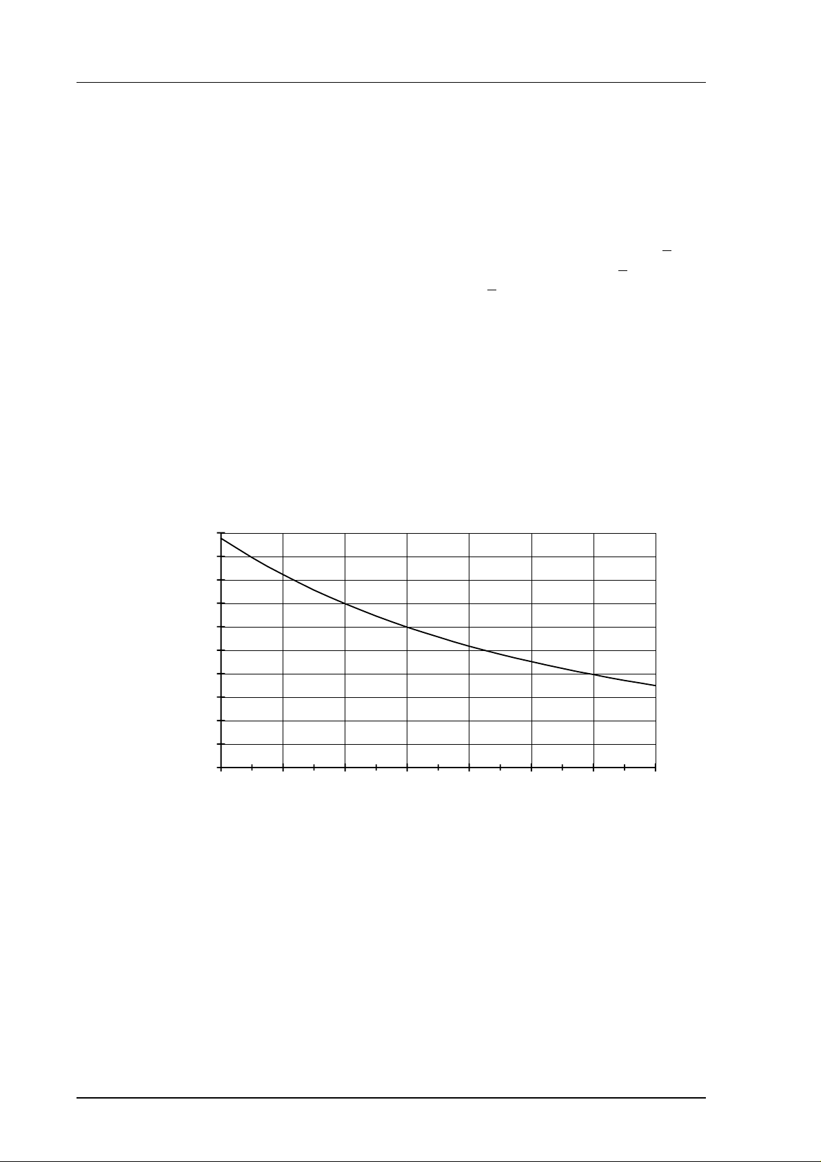
2. TO BE NOTED WHEN MEASURING HUMIDITY
In the measurement of humidity and especially in calibration, it is essential
that the temperature equilibrium is reached. Even a slight difference in the
temperature between the measured object and the sensor causes an error. For
example, at +20 °C (+ 68 °F) and 50 %RH, a temperature difference of +1 °C
between the measured object and the sensor causes an error of +3 %RH. If
relative humidity is 90 %RH, the error is about +5.4 %RH.
The error is at its greatest when the temperature of the sensor differs from that
of the surroundings and the humidity is high. A few degrees’ difference in
temperature may cause water to condense on sensor surface. Efficient
ventilation accelerates evaporation whereas in an unventilated space, it may
take hours. The HUMICAP180 sensor returns to its normal functioning as
soon as water has evaporated. Any contaminated water condensing on the
sensor may shorten its life span and change the calibration.
10
9
8
7
6
5
4
dRH (%RH)
3
2
1
0
-40-200 20406080100
Temperature (°C)
Figure 2.1 Measurement error at 100 %RH when the temperature
difference between th e ambient and the sensor i s 1 °C
2 1997-07-31
Page 7

HMD60U/Y Transmitters
U301en-1.1 Operating Manual
3. INSTALLATION
3.1 Selecting the place of installation
Select a place that gives a true picture of the environment or process and is as
clean as possible. Air should circulate freely around the sensor. A rapid air
flow is recommended as it ensures the same temperature for the ambient air
and the sensor head.
Install the transmitter in a place where no cold or hot spot can develop. If the
sensor head is installed in a duct or channel where the temperature is different
from the ambient temperature, insulate the point of entry. An uninsulated
installation might lead to condensation on the sensor head and even if no
condensation occurs, the resultant air flow may change the temperature near
the sensor head and distort the readings.
3.2 Mounting
Mount the transmitter with two screws. Place the drilling template on the duct
surface and drill the holes as indicated. Remember to drill an additional hole
for calibration purposes.
250 (9.84)62 (2.44)
Ø 12
(0.47)
100 (3.94)
100 (3.94)
Mounting hole 82 (3.23)>>>
Mounting hole 82 (3.23)>>>
Figure 3 Dimensions of the HMD60U/Y (in mm)
1997-07-31 3
Page 8

HMD60U/Y Transmitters
Operating Manual U301en-1.1
3.3 Grounding
Open the lid and mount the cable bushing set 18941HM. Do the grounding
according to Figure 3.3. When connecting the signal cable to the transmitter
housing, fold the cable braid between the brass disk in order to achieve the
best possible EMC performance. Do not leave the bare shield of the
connected wires so that it can shortci rcuit the el ectronics!
flexible wires 0.5 mm²
(AWG 20), stranded wires
recommended
3
140
165
braid
brass
disks
rubber
ring
nut
cable
25
D = Ø 7...10mm
(If the cable diameter is less
than 7mm, use a shrinking
tube or an adhesive tape)
shielding tube
braid
brass disks
Figure 3.3 Signal cable grounding with bushing 18941HM
4 1997-07-31
Page 9

HMD60U/Y Transmitters
U301en-1.1 Operating Manual
3.4 Electrical connections
Connect the signal cables to a removeable 5-pole screw connector. Make
connections according to Figure 3.4. RH test and T test connectors are used
with the HMI41 indicator and calibration cable 19116ZZ.
RH
TEST
RH GAIN
12345
-RH +T+RH -T
+
or
mA
mA
T GAIN
RH OFFSET
T OFFSET
Figure 3.4 Electrical connections
T
TEST
-
+
-
or
mA mA
1997-07-31 5
Page 10

HMD60U/Y Transmitters
Operating Manual U301en-1.1
3.5 Electronics
SCREWS
LID
SCREW TERMINAL
10528HM
TO REMOVE THE SENSOR HEAD:
1. Open the lid
2. Disconnect the screw terminal
3. Open the screws (2 pcs)
4. Pull out carefully
TO REINSTALL THE SENSOR HEAD:
1. Push in the sensor head
2. Fasten the screws
3. Connect the screw terminal
4. Close the lid
18941HM
GLANDS
SPARE PART SENSOR
HUMICAP180
MEMBRANE FILTER
part no. 17039HM
STAINLESS STEEL SINTERED FILTER
part no. HM46670
Figure 3.5 Electronics (can be disconnected ), accessories, spare parts
6 1997-07-31
Page 11

HMD60U/Y Transmitters
U301en-1.1 Operating Manual
4. CALIBRATION
4.1 One-point humidity calibration
The accuracy is recommended to be checked at least once a year; the interval
depends on the operating conditions and the required accuracy of the
measurement. The transmitter calibration can be conveniently checked with
the HMI41 indicator equipped with an appropriate probe and optional
calibration cable. If adjustment is needed, use the one-point calibration
potentiometer. If you prefer to calibrate the HMD60U/Y transmitters against
saturated salt solutions, use LiCl (11 %RH) and NaCl (75 %RH) solutions.
4.2 Two-point humidity calibration
The calibration can also be done with salt calibrators, or the instrument can be
sent to Vaisala or a Vaisala representativ e.
4.2.1 Two-point humidity calibration procedure
• Leave the calibrator and the transmitter for at least 30 minutes in the
same space so that their temperatures have time to equalize.
• Place the probe into the calibration hole of the LiCl bottle in the
humidity calibrator.
• Wait for 10 minutes.
• Use the RH offset potentiometer (see Figure 3.4) to adjust the output
signal to the value given in the calibration table (Chapter 4.3).
• Place the probe into the calibration hole of the NaCl bottle in the
calibrator.
• Wait for 10 minutes.
• Check that the reading corresponds within the desired accuracy to the
reading given in the calibration table. If not, adjust the reading with
the RH gain potentiometer (see Figure 3.4).
• Check again the reading at the first point and adjust if necessary.
1997-07-31 7
Page 12

HMD60U/Y Transmitters
Operating Manual U301en-1.1
4.3 Calibration table
Temperature °C 15 20 25 30 35
°F 59 68 77 86 95
LiCl %RH *) 11.3 11.3 11.3 11.3
4...20 mA mA 5.81 5.81 5.81 5.81
0...20 mA mA 2.26 2.26 2.26 2.26
0...1 V V 0.113 0.113 0.113 0.113
0...5 V V 0.565 0.565 0.565 0.565
0...10 V V 1.13 1.13 1.13 1.13
NaCl %RH 75.6 75.5 75.3 75.1 74.9
4...20 mA mA 16.10 16.08 16.05 16.02 15.98
0...20 mA mA 15.12 15.10 15.06 15.02 14.98
0...1 V V 0.756 0.755 0.753 0.751 0.749
0...5 V V 3.780 3.775 3.765 3.755 3.745
0...10 V V 7.56 7.55 7.53 7.51 7.49
*) LiCl solution must not be used or stored in temperatures below +18 °C (+64 °F) ;
otherwise the equilibrium humidity of the salt solution changes permanently
Table 1 Greenspan’s calibration table with output values accordin g to
the chosen scale
5. MAINTENANCE
5.1 Replacing the HUMICAP180 sensor and the filter
Remove the damaged sensor and insert a new one. Handle the sensor by the
plastic socket. DO NOT TOUCH THE SENSOR PLATE. Recalibrate the
transmitter.
Replace a dirty filter (membrane or sintered) to ensure a maximum lifetime
and a fast response for the sensor. Do not try to clean the filter.
8 1997-07-31
Page 13

HMD60U/Y Transmitters
U301en-1.1 Operating Manual
6. TECHNICAL DATA
6.1 Relative humidity
Measurement range 0...100 %RH
Accuracy at +20 °C:
%RH
3
2
1
0
10 4020 605030 8070
0 90 100
-1
-2
-3
Temperature dependence:
%RH
2.0
1.5
1.0
0.5
0
-20 200
-0.5
-1.0
-1.5
-2.0
%RH
8040 60 °C10-10 30 50 70
Humidity sensor HUMICAP180
Response time (90%) at 20 °C in still air 15 s with membrane filter
6.2 Temperature (Y model only)
Measurement range -20...+80 °C
Accuracy:
°C
0.8
0.6
0.4
0.2
0
-10
-0.2
-0.4
-0.6
-0.8
0-20 10 20 30 40 50 60 70 80 °C
Linearity better than 0.1 °C
Temperature sensor Pt 1000 IEC 751 class B
1997-07-31 9
Page 14

HMD60U/Y Transmitters
Operating Manual U301en-1.1
6.3 General
Supply voltage 10...35 VDC (RL= 0Ω)
20...35 VDC (RL=500Ω)
Output signal 4...20 mA
Operating temperature range:
electronics -5...+55 °C
sensor head -40...+80 °C
Storage temperature range -40...+80 °C
Housing:
sensor head stainless steel
electronics housing cast aluminium
Cable lead-through:
bushing for 7...10 mm (PG9) cable
(housing IP65 / NEMA 4),
part no. 18941HM
or armoured cable glands part no. 10528HM
Sensor protection:
standard membrane filter
(part no. 17039HM)
option stainless steel sintered filter
(part no. HM46670)
Connections screw terminals 0.5...1.5 mm
2
10 1997-07-31
Page 15

HMD60U/Y Transmitters
U301en-1.1 Operating Manual
6.4 Electromagnetic compatibility
The emission and immunity tests have been performed according to standards
EN50081-1 and EN50082-1.
6.4.1 Emissions
Test Setup according to Performance
Radiated interference EN55022 class B
6.4.2 Immunity
Test Setup according to Performance
Electrostatic discharge IEC 801-2:1991 criteria B
Electrical fast transients IEC 801-4:1988 criteria B
RF-radiated fields IEC 801-3:1984 criteria A
*GSM-field immunity ENV50204:1995 criteria A
(*additional test)
GUARANTEE
Vaisala issues a guarantee for the material and
workmanship of this product under normal operating
conditions for one year from the date of delivery.
Exceptional operating conditions, damage due to
careless handling or misapplication will void the
guarantee.
1997-07-31 11
Page 16

Page 17

Page 18

www.vaisala.com
 Loading...