

Page 1

M212243EN-A
User Guide
HMD60 Series Humidity and Temperature
Transmitters for Ducts in HVAC
HMD65
Page 2

PUBLISHED BY
Vaisala Oyj
Vanha Nurmijärventie 21, FI-01670 Vantaa, Finland
P.O. Box 26, FI-00421 Helsinki, Finland
+358 9 8949 1
Visit our Internet pages at www.vaisala.com.
© Vaisala Oyj 2019
No part of this document may be
reproduced, published or publicly
displayed in any form or by any means,
electronic or mechanical (including
photocopying), nor may its contents be
modified, translated, adapted, sold or
disclosed to a third party without prior
written permission of the copyright holder.
Translated documents and translated
portions of multilingual documents are
based on the original English versions. In
ambiguous cases, the English versions are
applicable, not the translations.
The contents of this document are subject
to change without prior notice.
Local rules and regulations may vary and
they shall take precedence over the
information contained in this document.
Vaisala makes no representations on this
document’s compliance with the local
rules and regulations applicable at any
given time, and hereby disclaims any and
all responsibilities related thereto.
This document does not create any legally
binding obligations for Vaisala towards
customers or end users. All legally binding
obligations and agreements are included
exclusively in the applicable supply
contract or the General Conditions of Sale
and General Conditions of Service of
Vaisala.
This product contains software developed
by Vaisala or third parties. Use of the
software is governed by license terms and
conditions included in the applicable
supply contract or, in the absence of
separate license terms and conditions, by
the General License Conditions of Vaisala
Group.
Page 3

Table of Contents
Table of Contents
1. About This Document................................................................................... 3
1.1 Version Information..........................................................................................3
1.2 Related Manuals................................................................................................3
1.3 Documentation Conventions...........................................................................3
1.4 Trademarks........................................................................................................ 4
2. Product Overview........................................................................................... 5
2.1 Introduction to HMD60 Series.........................................................................5
2.2 HMD65 Basic Features and Options...............................................................5
2.3 Available Parameters and Default Scaling.....................................................5
2.4 Connectivity to Vaisala Insight Software....................................................... 6
2.5 Transmitter Parts...............................................................................................7
2.5.1 Cable Gland and Conduit Options...........................................................8
2.5.2 Filter Options..............................................................................................8
2.5.3 Transmitter Board......................................................................................9
2.5.4 Trimmers................................................................................................... 10
2.5.5 DIP Switch Humidity Output Selection...................................................11
2.6 Filtering Factor.................................................................................................12
2.7 Environmental Compensation........................................................................12
3. Installation........................................................................................................ 13
3.1 Transmitter Dimensions..................................................................................13
3.2 Duct Mounting Overview................................................................................14
3.3 Installing into Duct.......................................................................................... 15
3.4 Wiring............................................................................................................... 16
4. Operating with Insight PC Software......................................................18
4.1 Vaisala Insight Software................................................................................. 18
4.2 Connecting to Insight Software.....................................................................18
4.3 Insight Main View............................................................................................ 19
4.3.1 Basic and Advanced User Modes..........................................................20
4.4 Configuring Analog Outputs with Insight...................................................20
4.4.1 Testing and Adjusting Analog Output Voltage (V) Level....................21
4.5 Configuring Minimum and Maximum RH and T Errors with Insight.........22
4.6 Changing Pressure Compensation Settings with Insight..........................24
4.7 Setting Filtering Factor with Insight............................................................ 25
5. Modbus and BACnet Communication..................................................26
5.1 Modbus and BACnet Overview.....................................................................26
5.2 Modbus and BACnet Configuration with Insight........................................ 27
5.2.1 Configuring Modbus Response Delay with Insight.............................28
5.2.2 Configuring BACnet with Insight...........................................................28
6. Operating with MI70 Indicator............................................................... 30
6.1 Overview of MI70 Support............................................................................30
6.1.1 MI70 Indicator Parts............................................................................... 30
1
Page 4

HMD65 User Guide M212243EN-A
6.2 Connecting HMD60 to MI70 Indicator.......................................................... 31
6.3 Basic Display................................................................................................... 32
6.4 Graphical Display............................................................................................32
6.5 Main Menu....................................................................................................... 32
6.6 Holding and Saving the Display....................................................................33
6.7 Recording Data............................................................................................... 33
7. Calibration and Adjustment.....................................................................34
7.1 Calibration and Adjustment Overview........................................................ 34
7.2 Calibration and Adjustment Using Trimmers.............................................. 34
7.2.1 1-Point Adjustment Using Trimmers and Reference Calibrator.........35
7.2.2 Adjusting Output Using Trimmers and Reference
Transmitter (1-point adjustment).......................................................... 35
7.2.3 Resetting Trimmers Back to Zero..........................................................36
7.3 Calibration and Adjustment with Insight PC Software.............................. 37
7.3.1 2-Point Adjustment with Insight and Reference Calibrator...............38
7.3.2 1-Point Adjustment with Insight and Reference Transmitter............. 38
7.4 Calibration and Adjustment with MI70 Hand-Held Indicator...................40
7.4.1 1-Point Adjustment Using Reference Environment............................40
8. Maintenance....................................................................................................43
8.1 Cleaning........................................................................................................... 43
9. Technical Data............................................................................................... 44
9.1 Specifications................................................................................................. 44
9.2 Spare Parts and Accessories.........................................................................46
9.3 Transmitter Dimensions.................................................................................47
Appendix A:
Modbus Registers.................................................................. 48
A.1 Measurement Data Registers........................................................................48
A.2 Status Registers...............................................................................................51
A.3 Configuration Registers.................................................................................53
A.4 Communication Test Registers.....................................................................53
Appendix B:
BACnet Reference..................................................................54
B.1 BACnet Protocol Implementation Conformance Statement ................... 56
B.2 Device Object..................................................................................................59
B.3 Relative Humidity Object.............................................................................. 62
B.4 Temperature Object.......................................................................................64
B.5 Calculated Humidity Objects........................................................................ 67
B.6 Operation Pressure Object............................................................................69
B.7 BIBBs Supported............................................................................................ 70
B.8 Application Services Supported....................................................................71
Warranty............................................................................................................ 75
Technical Support............................................................................................ 75
Recycling........................................................................................................... 75
2
Page 5
Chapter 1 – About This Document
1. About This Document
1.1 Version Information
Table 1 Document versions
Document Code Date Description
M212243EN-A April 2019 This manual. First version of the document.
1.2 Related Manuals
Table 2 Related Manuals
Document Code Description
M212264EN HMD65 Multilingual Quick Guide
M212016EN HMD62 and TMD62 User Guide
M212049EN HMD62 and TMD62 Multilingual Quick Guide
1.3 Documentation Conventions
WARNING!
instructions carefully at this point, there is a risk of injury or even death.
CAUTION!
instructions carefully at this point, the product could be damaged or important
data could be lost.
Note highlights important information on using the product.
Tip gives information for using the product more eciently.
alerts you to a serious hazard. If you do not read and follow
warns you of a potential hazard. If you do not read and follow
3
Page 6

HMD65 User Guide M212243EN-A
1.4 Trademarks
Vaisalaâ and HUMICAPâ are registered trademarks of Vaisala Oyj.
Windowsâ is either a registered trademark or trademark of Microsoft Corporation in the
United States and other countries.
All other product or company names that may be mentioned in this publication are trade
names, trademarks, or registered trademarks of their respective owners.
4
Page 7

Chapter 2 – Product Overview
2. Product Overview
2.1 Introduction to HMD60 Series
The duct mounted HMD60 HUMICAPâ Humidity and Temperature Transmitters are designed
for monitoring humidity and temperature in demanding HVAC and light industrial applications.
HMD60 series transmitters provide stable, reliable, and highly accurate (up to ±1.5 %RH and
±0.1 °C (0.18 °F)) measurements, and are resistant to chemicals and dust.
HMD60 series transmitter options include the HMD62 and TMD62 analog output transmitters
with loop powered 4 … 20 mA current output, and the analog and digital output transmitter
HMD65 with analog voltage output (0 … 10 V) and digital Modbus RTU and Bacnet output
(RS-485).
Thanks to easy access to electronics also when the transmitter is installed to a duct,
configuration and adjustment can be carried out quickly and conveniently. Available
configuration and adjustment interface options range from physical trimmers and DIP switches
on the transmitter's circuit board to Modbus, BACnet, and Vaisala Insight PC software for
Windowsâ.
2.2
HMD65 Basic Features and Options
• Humidity and temperature measurement:
• available humidity parameters: RH, Td, Tdf, A, X, Tw, H
• T measurement in °C or °F
• Analog output: 2 analog 0 … 10 V output channels for humidity and temperature
measurements
• Digital output (RS-485): Modbus RTU and BACnet MS/TP
• Power supply input: 15 … 35 VDC / 16 … 24 VAC
• Configuration and adjustment options:
• RH and T measurement field adjustment with trimmers
• Humidity output parameter selection and Modbus/BACnet serial setting configuration
with DIP switches
• Configuration and adjustment with Vaisala Insight PC software
• Configuration with Modbus and BACnet
• Field adjustment with MI70 hand-held indicator
2.3
Available Parameters and Default Scaling
HMD65 Measurement Parameters and Default Analog Output
Scaling
Table 3 (page 6) shows the available output parameters and the default analog output
scaling of the parameters for HMD65.
5
Page 8

HMD65 User Guide M212243EN-A
Table 3 HMD65 Measurement Parameters and Default Scaling
Parameter Default Scaling for 1 … 10 V Output Range
Relative humidity (RH) 0 … 100 %RH
Temperature (T) -20 ... +80 °C (-4 ... +176 °F)
Dew point temperature (Td) -40 ... +80 °C (-40 ... +176 °F)
Dew point/frost point
temperature (Tdf)
Absolute humidity (A)
Mixing ratio (X) 0 … 600 g/kg (0 … 4200 gr/lb)
Wet-bulb temperature (Tw) -40 ... +80 °C (-40 ... +176 °F)
Enthalpy (H) -40 … 1600 kJ/kg (-9.5 ... 695.6 Btu/lb)
-40 ... +80 °C (-40 ... +176 °F)
0 … 300 g/m3 (0 … 131.1 gr/ft3)
Changing Measurement Parameter Scaling
If your application requires an analog output scaling that diers from the defaults shown in
Table 3 (page 6), you can configure the scaling by connecting the transmitter to Vaisala Insight
PC software (requires Vaisala USB cable 219690).
2.4
Connectivity to Vaisala Insight Software
The transmitter can be connected to Vaisala Insight software using a Vaisala USB cable (order
code 219690). With the Insight software, you can:
• See device information and status.
• See real-time measurement.
• Configure output parameters and scaling.
• Configure serial communication settings.
More Information
‣
Connecting to Insight Software (page 18)
6
Page 9
2.5 Transmitter Parts
1
2
3
4
5
6
7
8
9
Chapter 2 – Product Overview
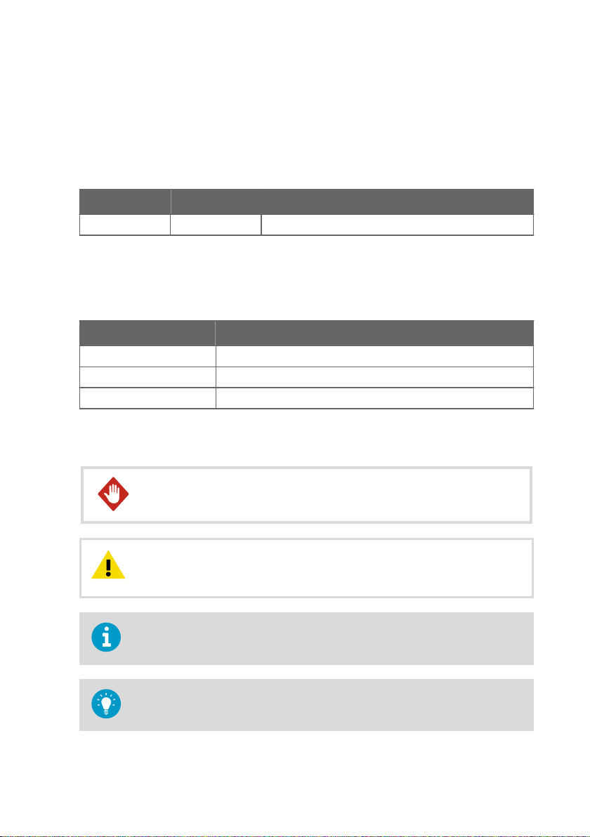
Figure 1 HMD65 Transmitter Parts Overview
Captive screw (2 pcs, cross-head) for attaching the lid of the transmitter.
1
2 Screw (2 pcs) for mounting the transmitter on the installation surface.
3 Transmitter lid. Open the captive screws of the lid to access input and output electronics.
4 Transmitter base. Contains the input and output connectors on the transmitter board: see
Transmitter Board (page 9).
5 Cable gland (M16 x 1.5 lead-through) for leading wires into the transmitter.
6 Alternative lead-through (M20 x 1.5) for wiring.
7 Probe body. Long (shown) and short probe options available: see Transmitter Dimensions
(page 13).
8 Probe filter (default option: AISI 316L stainless steel).
9 HUMICAPâ sensor inside the probe filter.
Do not touch the sensor element.CAUTION!
7
Page 10
1
2
1 2
HMD65 User Guide M212243EN-A
2.5.1 Cable Gland and Conduit Options
HMD60 has 2 lead-throughs (M16x1.5 and M20x1.5) that can be used with a variety of cable
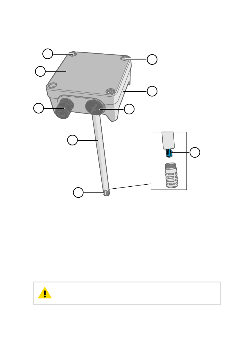
gland and conduit options. Figure 2 (page 8) shows the cable gland and conduit options
available from Vaisala.
Figure 2 HMD60 Cable Gland and Conduit
Options
1 Cable Gland and O-ring M16 x 1.5
(Vaisala order code: 254280SP). This is
the default option delivered with
HMD60.
2 Conduit fitting and O-ring (M16x1.5 /
NPT1/2") (Vaisala order code:
210675SP).
2.5.2 Filter Options
Figure 3 (page 8) shows the filter options available for HMD60.
Figure 3 HMD60 Filter Options
Metal Grid with PTFE Membrane (Vaisala order code ASM212652SP). This is the default
1
option delivered with HMD60.
2 Sintered Filter (Vaisala order code HM46670SP).
8
Page 11
2.5.3 Transmitter Board
4
5
6
7
8
3
2
1
9
10
11
12
13
Chapter 2 – Product Overview
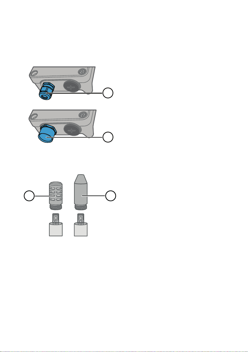
Figure 4 HMD65 Transmitter Board: Service Port, DIP switches, Trimmers, and Screw Terminals
RS-485 termination (120 Ω resistor) ON/OFF switch.
1
2 RS-485 (Modbus/BACnet) screw terminals.
3 Power supply input (15 … 35 VDC or 16 … 24 VAC) screw terminals.
4 Service port for MI70 hand-held indicator and Insight PC software cable connection.
5 DIP switches for setting the HMD65 Modbus RTU or BACnet MS/TP MAC address.
6 DIP switches for selecting Modbus/BACnet communication bit rate and parity (Modbus
7 DIP switches for humidity output parameter selection.
8 DIP switch for selecting either Modbus or BACnet mode.
9 Trimmer for humidity measurement adjustment.
10 Screw terminals for humidity measurement output.
11 Screw terminals for temperature measurement output.
12 Trimmer for temperature measurement adjustment.
13 Indicator LEDs: flash when there is RS-485 transmit (TX) or receive (RX) activity.
More Information
‣
‣
only).
Wiring (page 16)
Modbus and BACnet Overview (page 26)
9
Page 12

1
±0 %RH
−1 %RH
−2 %RH
−3 %RH
−4 %RH
−5 %RH
+1 %RH
+2 %RH
+3 %RH
+4 %RH
+5 %RH
±0 °C
−0.06 °C
−0.12 °C
−0.18 °C
−0.24 °C
−0.3 °C
+0.06 °C
+0.12 °C
+0.18 °C
+0.24 °C
+0.3 °C
RH: −5 %RH ... +5 %RH T: −0.3 °C ... +0.3 °C
RH T
HMD65 User Guide M212243EN-A
2.5.4 Trimmers
Figure 5 Component Board Adjustment
Trimmer
1 Use a Phillips head screwdriver (PH0)
to rotate the RH or T adjustment
trimmer. To increase the measurement
output value, rotate the trimmer
clockwise. To decrease, rotate
counterclockwise.
Note that there is a slight delay before
the measurement output changes
after rotating the trimmer.
You can adjust the transmitter's RH or T measurement output with the trimmers on the
component board. During trimmer adjustment, the output of the transmitter is corrected using
the trimmers until the output matches the known value of a reference.
Figure 6 RH and T Trimmer Adjustment Ranges (Indicative)
You can only calibrate the relative humidity measurement (RH) and temperature
measurement (T). Other parameters (available for HMD62) are calculated
internally based on RH and T. Check that the output selection DIP switch is set to
RH when making adjustments with the physical trimmer; when using the Insight
PC software, set all DIP switches to the OFF position.
CAUTION!
restore the factory settings, always return the physical trimmer to the middle
position before starting. When you make an adjustment with Insight, the
10
position in which the trimmer is at that point is set as the ±0 point.
If you use the Insight PC software to adjust the measurement or to
Page 13
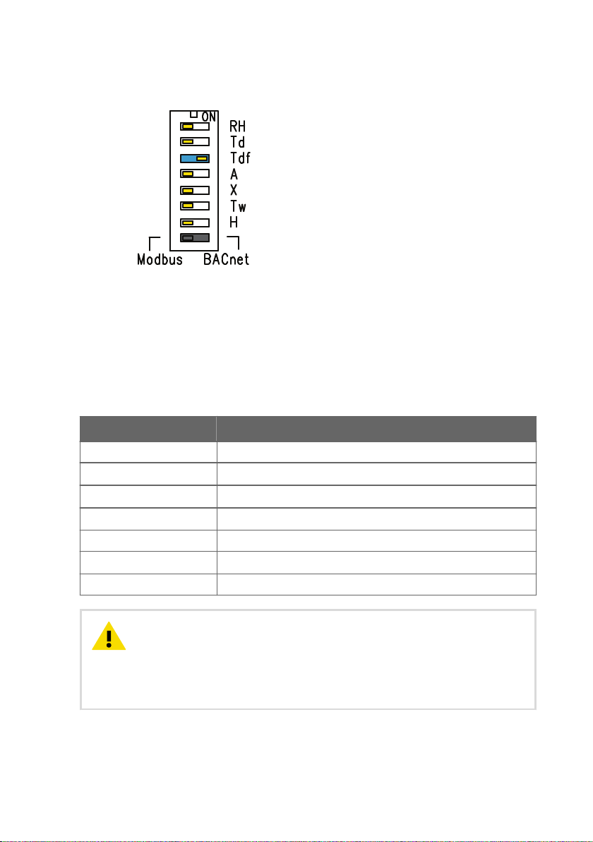
2.5.5 DIP Switch Humidity Output Selection
Chapter 2 – Product Overview
Figure 7 HMD65 DIP Switch Example: T
Output Selected
df
RH Relative humidity
Td Dew point temperature
Tdf Dew point/frost point temperature
A Absolute humidity
X Mixing ratio
Tw Wet-bulb temperature
H Enthalpy
You can change the humidity parameter that is output on the RH channel of HMD65 with the
DIP switches on the component board. Select the parameter you want the transmitter to
output by sliding the parameter's DIP switch to the right (ON). In the example in Figure 7
(page 11), the selected output parameter is dew point/frost point temperature (Tdf). Keep the
other DIP switches in the OFF position (left).
The selected parameter uses the default scaling shown in Table 4 (page 11).
Table 4 HMD65 Default Parameter Scaling
Parameter Default Scaling for 0 … 10 V Output Range
RH 0 … 100 %RH
T
d
T
df
A
X 0 … 600 g/kg (0 … 4200 gr/lb)
T
w
H -40 … 1600 kJ/kg (-9.5 ... 695.6 Btu/lb)
-40 ... +80 °C (-40 ... +176 °F)
-40 ... +80 °C (-40 ... +176 °F)
0 … 300 g/m3 (0 … 131.1 gr/ft3)
-40 ... +80 °C (-40 ... +176 °F)
CAUTION!
Note that the humidity output parameter selected with the DIP
switches on the transmitter component board will be used instead of the
parameter selected with Insight. When using Insight to configure the output, set
all humidity parameter selection DIP switches on the transmitter component
board to the OFF position (left) to ensure they do not cause a conflict with the
Insight settings.
11
Page 14

HMD65 User Guide M212243EN-A
If you use Insight to set both analog output channels to output T measurement,
the humidity parameter DIP switches do not have an eect on the output.
2.6 Filtering Factor
If the measuring environment produces occasional exceptionally high or low readings that
need to be averaged out in the output, you can apply a filtering factor to the RH or T output
(filtering factor range: 0.001 … 1.000). The filtering factor defines the speed at which the latest
measurement is integrated into the transmitter's output. By default, the filtering factor is set to
0.500, which means that the displayed output is a 50%+50% combination of the previous
measurement and the most recent measurement. To show the latest measurement directly in
the output, set the filtering factor to 1.000 (no filtering).
The following formula is used when calculating the output:
output = [(new (unfiltered) measurement × filtering factor) + (previous output × (1.0 - filtering
factor))]
The filtering factor can be configured with the Insight PC software.
More Information
‣
Setting Filtering Factor with Insight (page 25)
2.7
Environmental Compensation
By default, the pressure value used in HMD65 measurement calculation is 1013.2 hPa. If the
pressure of your measurement environment diers from this, you can configure the
transmitter's pressure compensation value with the Insight PC software.
More Information
‣
Changing Pressure Compensation Settings with Insight (page 24)
12
Page 15
3. Installation
299 [11.77]
49 [1.92]
250 [9.84]
101 [3.97]
mm
[in]
101 [3.97]
82[3.23]
82 [3.23]
Ø 12 [0.47]
19.5 [0.77]
149 [5.87]
49 [1.92]
100 [3.94]
101 [3.97]
Ø 12 [0.47]
19.5 [0.77]
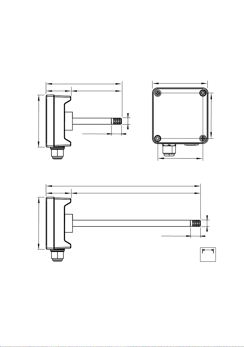
3.1 Transmitter Dimensions
The dimensions are given in millimeters and [inches].
Chapter 3 – Installation
Figure 8 Dimensions with Long and Short Probe
13
Page 16
90°
1
4
3
2
5
6
7
HMD65 User Guide M212243EN-A
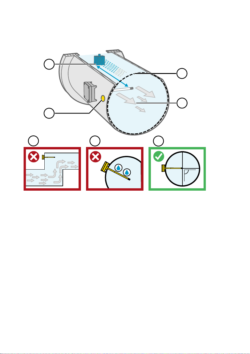
3.2 Duct Mounting Overview
Figure 9 Duct Installation Overview
Make sure there is a minimum clearance of 5 m (16.5 ft) between the probe body and any
1
possible humidifier. Avoid installing in a location where condensation can fall on the
sensor inside the duct.
2 When installing the transmitter, drill a second hole approximately 30 cm (12 in) from the
installation hole, towards the direction of the air flow, and plug it with a removable seal.
This second hole is intended for later use in reference measurement with another device
when calibrating or adjusting the transmitter.
3 Check that the duct diameter is suitable for the probe body (see Transmitter Dimensions
(page 13)). Ideally, the sensor (probe head) should be installed in the middle of the duct.
4 Maximum air flow speed: 50 m/s (with sintered filter).
5 Avoid installing the transmitter in dead legs. Supersaturation can occur in areas where
there is no air flow.
6 Do not install the probe in a downward angle. Condensation can travel to the sensor along
the probe body if the probe points down.
7 Install the probe in a 90° angle so that the sensor is placed as close to the middle of the
duct as possible.
14
Page 17
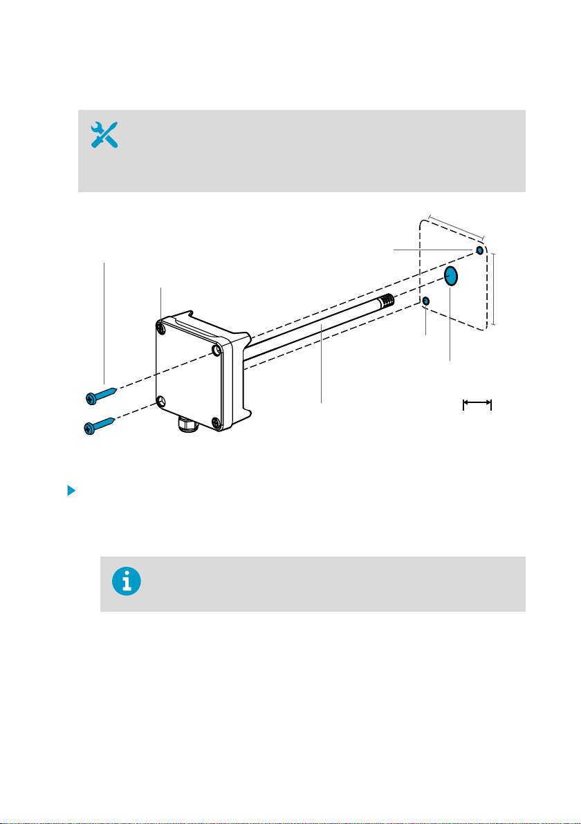
3.3 Installing into Duct
2 x Ø 3.5 [0.14]
Ø 13 ... 15 [0.51 ... 0.59]
Ø 12 [0.47]
82 [3.23]
82 [3.23]
mm
[in]
Ø 3.5 [0.14]
Ø 3.5 [0.14]
3.1 ... 3.4 Nm [2.3 ... 2.5 ft-lbs]
• Medium size crosshead screwdriver for mounting screws and lid screws.
• Small slotted screwdriver for screw terminals.
• Drill with 3.5 mm (0.14 in) and 13 … 15 mm (0.51 … 0.59 in) bits for making the
installation holes.
• Tools for cutting and stripping wires.
Chapter 3 – Installation
Figure 10 Drilling and Mounting Screws
1. Select an installation location for the transmitter on the duct surface and drill a
Ø 13 … 15 mm (0.51 … 0.59 in) hole for inserting the probe.
2. Push the probe through the hole on the duct until the transmitter body meets the duct.
3. Attach the transmitter body to the duct with 2 Ø 3.5 mm (0.14 in) screws.
Check that the insulation ring sits tightly over the installation hole. If the duct
has a negative pressure, external air can be drawn into the duct and aect
the measurement if the installation hole is not sealed tightly.
4. Optional: Drill a second hole for reference measurements approximately 30 cm (12 in)
from the transmitter installation hole. See Figure 9 (page 14).
5. Open the 2 captive screws on the transmitter body and remove the lid.
6. Attach the input/output wiring to the screw terminals on the transmitter component
board. See Wiring (page 16). Tighten cable glands firmly after wiring.
7. Check that the DIP switches and trimmers are in the correct position. See Transmitter
Board (page 9) for more information on DIP switches and trimmers.
15
Page 18

0 ... 10 V ANALOG OUTPUT WIRING
DIGITAL (RS-485) COMMUNICATION WIRING
CONTROLLER
RS-485 +
RS-485 -
RSGND
HMD65
HMD65
+
-
V
V
POWER SUPPLY
(16 ... 24 VAC)
15 ...35 VDC
1)
1)
1) HMD65 GROUNDING SCREW TERMINALS ARE INTERNALLY
CONNECTED TO HMD65 CHASSIS GROUNDING.
CONNECT GROUNDING AS APPLICABLE
TO INSTALLATION SITE WIRING IMPLEMENTATION.
1)
CONTROLLER
+
-
POWER SUPPLY
(16 ... 24 VAC)
15 ...35 VDC
ANALOG INPUT
ANALOG INPUT GROUND
ANALOG INPUT
ANALOG INPUT GROUND
HMD65 User Guide M212243EN-A
8. Close the transmitter lid and switch on the transmitter's power supply input.
3.4 Wiring
Figure 11 HMD65 Wiring Diagrams (Analog and Digital Output Options)
16
Page 19

Chapter 3 – Installation
• Screw terminal wire size: 0.5 ... 2.5 mm
2
• Flat head screwdriver: 0.6×3.5 mm
Make sure that you prepare or connect only de-energized wires.WARNING!
CAUTION!
Do not connect any wires to unused terminals (for example, if you
are using only analog outputs, do not connect wires to the RS-485 terminals).
Connecting unnecessary wires can increase the power consumption and cause
heating.
17
Page 20
HMD65 User Guide M212243EN-A
4. Operating with Insight PC Software
4.1 Vaisala Insight Software
Vaisala Insight software is a configuration software for Vaisala Indigo-compatible probes and
transmitters. The supported operating systems are Windows 7 (64-bit), Windows 8.1 (64-bit),
and Windows 10 (64-bit).
To ensure support for your HMD60 series transmitter, download the latest version
of Insight at www.vaisala.com/insight.
With the Insight software, you can:
• See real-time measurements, device information and status.
• Configure outputs and scaling.
• Calibrate and adjust the device.
HMD60 can be connected to Insight using a Vaisala USB cable (order code 219690).
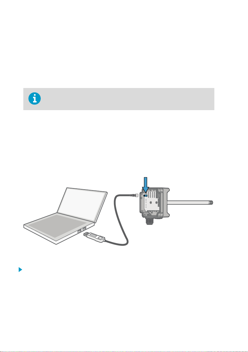
4.2
Connecting to Insight Software
Figure 12 Connecting Transmitter to Insight
1. Open the Insight software.
2. Connect the USB cable to a free USB port on the PC.
3. Connect the USB cable to the service port of the transmitter.
4. Wait for Insight software to detect the transmitter.
18
Page 21
Chapter 4 – Operating with Insight PC Software
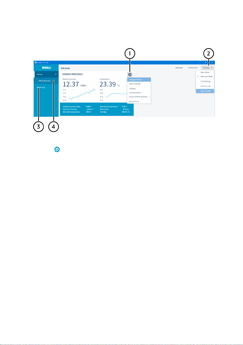
4.3 Insight Main View
Figure 13 Insight Main Menu and Settings
1 Select to access Insight main menu.
• Configure Device: environmental compensation settings, analog output 1 and 2
settings, Modbus and BACnet configuration, filtering factor, error limits and
general settings.
• Export Settings: creates a text file export of the device settings.
• Calibrate: options for calibrating and adjusting RH and T output, testing and
adjusting voltage (V) output levels, and restoring factory adjustments.
• Communication: contains a quick access selection for restarting the device.
• Factory Default Settings: restores the transmitter back to default settings, clears
any user adjustments and restores the latest factory calibration.
• About Device: general device information such as serial number and software
2 Select Settings to switch between the Basic Mode and Advanced Mode user modes,
3 Monitoring provides options for monitoring and recording selected parameters, and
4 Device information menu with the following tabs:
version.
change the units of parameters (metric/non-metric), enter a factory code to access
restricted functionalities, or view information about the Insight software.
exporting the monitoring data as a CSV (comma-separated values) file.
• Measurements: measurement graph view with parameter drop-down selection.
• Calibration Information: read-only information about the latest stored calibration.
• Diagnostics: troubleshooting and administrative information about the device
status. Also includes an option to export the device error log as a text file. When
contacting Vaisala support, it is recommended to include an up-to-date export of
the error log with the support request.
19
Page 22
HMD65 User Guide M212243EN-A
4.3.1 Basic and Advanced User Modes
You can switch between the Basic Mode and Advanced Mode user modes with the selections
in the Settings menu.
Certain functionalities are only available in Advanced Mode. The options enabled by switching
to Advanced Mode are often intended for administrative users: set the user mode according to
the requirements of the personnel that use the device.
4.4 Configuring Analog Outputs with Insight
CAUTION!
switches on the transmitter component board will be used instead of the
parameter selected with Insight. When using Insight to configure the output, set
all humidity parameter selection DIP switches on the transmitter component
board to the OFF position (left) to ensure they do not cause a conflict with the
Insight settings.
If you use Insight to set both analog output channels to output T measurement,
the humidity parameter DIP switches do not have an eect on the output.
Note that the humidity output parameter selected with the DIP
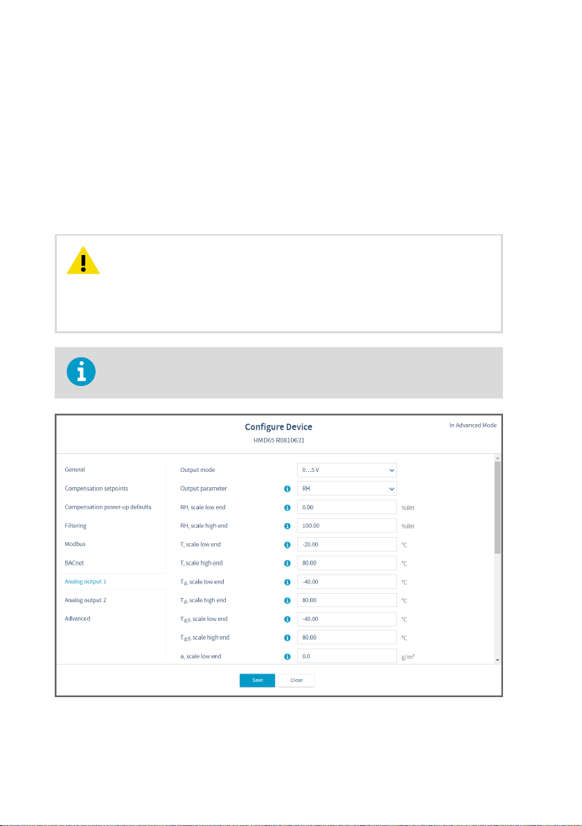
Figure 14 Analog Output Configuration Options in Insight
20
Page 23

Chapter 4 – Operating with Insight PC Software
To configure analog output with Insight:
1. Check that the output parameter selection DIP switches on the transmitter component
board are switched to the OFF position.
2. Connect to Insight and select > Configure Device > Analog Output 1[2].
3. Select the output mode (either 0 … 10 V, 0 … 5 V, 1 … 5 V, or O).
4. Select the output parameter.
The default analog output setup for HMD65 is 1 channel for RH and 1 channel
for T. Using Insight, you can set any RH and T output combination for the 2
channels (RH+RH, T+T, or RH+T).
5. Enter the lower and upper limits of the output scale for your selected parameter.
6. Set the error output value and the output clipping and error limits.
7. Select Save to store the configuration and exit the menu with Close when done.
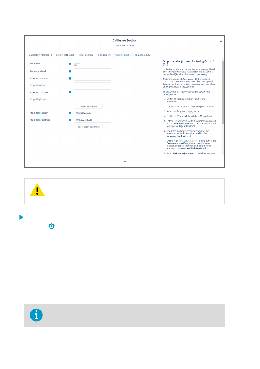
4.4.1 Testing and Adjusting Analog Output Voltage (V) Level
• Computer with Windows operating system and Vaisala Insight software
installed
• Vaisala USB cable 219690 for connecting the probe to Insight
• Multimeter for checking the analog output voltage reading
Note that configuring these settings requires using Insight in Advanced Mode.
You can test the voltage (V) output level of the transmitter with a multimeter, and adjust the
output level (2-point adjustment) if necessary.
21
Page 24
HMD65 User Guide M212243EN-A
CAUTION!
outputs to normal operating mode. The transmitter does not output
measurement data when the analog outputs are in test mode.
1. Switch to Advanced Mode in the Settings menu.
2. Select > Calibrate > Yes to switch the probe to calibration mode.
3. Select the analog output you want to test (Analog Output 1[2]).
4. Follow the instructions in the Insight interface to carry out required output tests and
adjustments.
4.5
Configuring Minimum and Maximum RH and T
Always switch Test mode o after testing to return the analog
Errors with Insight
You can define the minimum and maximum limit that the RH or T measurement output can
reach before the output moves to error state.
Note that configuring these settings requires using Insight in Advanced Mode.
22
Page 25

Chapter 4 – Operating with Insight PC Software
Figure 15 Minimum/Maximum Allowed Measurement Value Before Error
To define the minimum/maximum error limits:
1. Switch to Advanced Mode in the Settings menu.
2. Select
> Configure Device > Advanced.
3. Enter the values for minimum and maximum RH and T as applicable, select Save and exit
the menu with Close.
More Information
‣
Basic and Advanced User Modes (page 20)
23
Page 26

HMD65 User Guide M212243EN-A
4.6 Changing Pressure Compensation Settings with Insight
Figure 16 Pressure Compensation Settings
By default, the pressure value used when calculating HMD65 measurements is 1013.2 hPa.
To change the pressure compensation setting:
1. Select
2. To change the volatile compensation value (resets back to power-up default at device
restart), select Compensation setpoints, enter a value, and select Save.
3. To change the default compensation value that stays in use also after device restart, select
Compensation power-up defaults, enter a value, and select Save.
4. Select Close to exit the menu after you have saved the compensations.
More Information
‣
Environmental Compensation (page 12)
24
> Configure Device.
Page 27

Chapter 4 – Operating with Insight PC Software
4.7 Setting Filtering Factor with Insight
Figure 17 Filtering Factor Configuration View
1 Enable filtering by moving the slider to the right (ON)
To set a filtering factor for the transmitter's measurement output:
1. Select > Configure Device > Filtering.
2. Enable filtering with the ON/OFF selections (slide right to enable, left to disable).
3. Enter a filtering factor below 1.000 to apply filtering to the output (range: 0.001 … 1.000).
Examples of the eect of filtering on output:
• Filtering factor 1.000 = No filtering, the latest measurement is output
directly without integrating previous measurements.
• Filtering factor 0.500 = The reading output integrates 50% of the
previous measurement with the latest measurement.
• Filtering factor 0.100 = The reading output integrates 90% of the
previous measurement with the latest measurement.
4. Select Save when done and exit with Close.
More Information
‣
Filtering Factor (page 12)
25
Page 28

3
2
1
7
4 5 6
HMD65 User Guide M212243EN-A
5. Modbus and BACnet Communication
5.1 Modbus and BACnet Overview
HMD65 can be accessed with the Modbus and BACnet protocols over the RS-485 interface.
The protocol selection and communication settings for either protocol are entered with the
DIP switches on the HMD65 component board (see Figure 18 (page 26)).
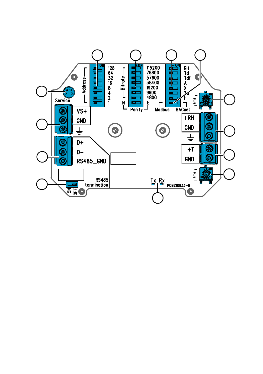
Figure 18 Modbus and BACnet DIP Switches and Screw Terminals on HMD65 Component Board
1
2 Screw terminals for RS-485 (Modbus/BACnet) communication
3 Screw terminals for power supply input wiring (15 … 35 VDC / 16 … 24 VAC)
4 DIP switches for setting the device MAC address: see Figure 19 (page 27)
5 DIP switches for setting the communication bitrate (4800 … 115200 bps) and parity (N/E)
6 DIP switch for selecting either Modbus RTU or BACnet MS/TP mode
7 LED indicators for RS-485 transmit/receive activity
DIP switch for setting RS-485 termination (120 Ω resistor) ON/OFF
Modbus
The Modbus variant used in HMD65 is Modbus RTU. For a list of the Modbus registers available
in HMD65, see Modbus Registers (page 48).
26
Page 29

Chapter 5 – Modbus and BACnet Communication
BACnet
The BACnet variant used in HMD65 is BACnet MS/TP. For a description of the HMD65 BACnet
implementation, see BACnet Reference (page 54).
Setting Device MAC Address with DIP Switches
Figure 19 MAC Address DIP Switch Example
DIP
switches 32,
8, and 1 set
to ON
The MAC address is
encoded in eight bit binary
form, with each numbered
switch representing a single
bit. This example shows
address 41 selected: DIP
switches 32, 8, and 1
(decimal: 41, binary:
00101001) are set to ON.
Modbus and BACnet MAC Address Ranges
The BACnet MS/TP MAC address range for the transmitter is 0 … 127 (master mode only).
The Modbus RTU MAC address range for the transmitter is 1 … 247.
Configuring an address above the range maximum results in the address defaulting back to
the maximum address (127 or 247). Addresses below the range minimum default to the
minimum address (0 or 1).
Bit Rate and Parity Options
• The bit rate 4800 is used only for Modbus RTU (use 9600 and above for BACnet MS/TP).
• If the bit rate DIP switches are all set to OFF (left), the following defaults are used:
• Modbus RTU: 19200
• BACnet MS/TP: 38400
• The parity selection (N/E) only has an eect on Modbus RTU communication.
5.2
Modbus and BACnet Configuration with
Insight
Modbus and BACnet communication settings are configured with the DIP switches on the
HMD65 component board (see Figure 18 (page 26)). In addition to the communication settings
available through the DIP switches, you can configure certain Modbus and BACnet settings
with Vaisala Insight PC software (requires Vaisala USB cable 219690).
For instructions on connecting HMD65 to Insight, see Connecting to Insight Software
(page 18).
27
Page 30

HMD65 User Guide M212243EN-A
5.2.1 Configuring Modbus Response Delay with Insight
Figure 20 Modbus Response Delay Setting in Insight
To configure Modbus response delay with Insight:
1. Connect to Insight and select > Configure Device > Modbus.
2. Enter the Response delay value in milliseconds: see the instructions in the Insight
interface for allowed ranges and additional information.
3. Select Save to store the setting.
5.2.2 Configuring BACnet with Insight
Figure 21 BACnet Device Information, MS/TP Master Address Poll Limit, and Remote Management
Password Settings in Insight
28
Page 31

Chapter 5 – Modbus and BACnet Communication
You can configure the following BACnet settings with Vaisala PC Insight software:
• Max_Master (highest address polled for MS/TP master)
• Device object identifier (BACnet ID of the device)
• Device object name (max. 40-character name for the device)
• Device location (max. 40-character location info for the device)
• Firmware revision (read-only version information)
• Remote management password (max. 20-character password for remote management,
default 1234)
To configure BACnet settings with Insight:
1. Connect to Insight and select > Configure Device > BACnet.
2. Enter the values for BACnet settings as necessary: see the instructions in the Insight
interface for allowed ranges and additional information.
3. Select Save to store the settings.
29
Page 32

6
5
4
3
2
1
HMD65 User Guide M212243EN-A
6. Operating with MI70 Indicator
6.1 Overview of MI70 Support
The MI70 hand-held indicator is a convenient service tool for viewing the measurement
readings and performing calibration and adjustment. MI70 is used as the display and
configuration tool in, for example, the HM70 Hand-Held Humidity and Temperature Meter, and
is also compatible with various Vaisala probes and transmitters.
You can use the MI70 indicator for the following tasks with HMD60:
• Measurement viewing and logging
• Calibration and 1-point adjustment (see Calibration and Adjustment with MI70 Hand-Held
Indicator (page 40))
• Viewing information about the transmitter (serial number, SW version, last adjustment
date)
To connect HMD60 to an MI70 indicator, you need the optional MI70 connection
cable (Vaisala order code 219980SP).
6.1.1 MI70 Indicator Parts
Figure 22 MI70 Indicator Parts
1 Charger socket
2 Function key shortcut buttons . The
functions change according to what
you are doing with the indicator.
3 Arrow buttons:
30
Move up in a menu
Move down in a menu
4 Power On/O button
5 Battery compartment at the back of
6 Two ports (labeled I and II) for
Enter a sub-menu
Return to previous menu level
the indicator
connecting probes and instruments.
Page 33

Chapter 6 – Operating with MI70 Indicator
To open menus, press an arrow button and then press the shortcut buttons. To activate a
function shown above the shortcut button, press the shortcut button. To navigate in the
menus, press arrow buttons.
6.2 Connecting HMD60 to MI70 Indicator
• MI70 connection cable (Vaisala order code 219980SP).
• Medium size crosshead screwdriver for opening the lid screws.
Figure 23 Connecting HMD60 to MI70 Indicator with Cable 219980SP
1. Open the 2 captive screws on the transmitter body and remove the lid.
2. If the MI70 indicator is on, turn it o.
3. Connect the MI70 connection cable 219980SP to HMD60 service port and either of the
MI70 connector ports.
4. Turn on the MI70 indicator (time and date are requested at first startup). MI70 detects
HMD60 and proceeds to show the measurement screen. MI70 will start to show valid
measurement results from HMD60 after a few seconds.
31
Page 34

HMD65 User Guide M212243EN-A
6.3 Basic Display
1 Measured parameter and compensations (up to three items on display simultaneously).
You can change the shown items in Main menu > Display > Quantities and units.
2 Battery indicator. Shows current status (charge) of the battery.
3 Function key Graphic shows the readings as a curve.
4 Function key Hold/Save freezes the display and you can save the reading in the MI70
memory.
5 Function key Record is a quick access to the Recording/Viewing menu.
Figure 24 MI70 Basic Display
You can change the default function key shortcuts (Graphic, Hold/Save, Record) to other
menus or functions in Main menu > Settings > User interface > Program shortcut keys.
6.4 Graphical Display
The graphical display shows you the measurements as a curve (the curve of the uppermost
quantity shown in the basic display). From the curve you can examine the data trend and
history of the last minutes.
To open the graphical display, select Graphic in the basic display or select Main menu >
Display > Graphic history > Show.
To get the statistical info on the graph area (minimum, maximum, and average values), press
Info.
To get the curve of the other selected quantities, press Next. To get the curves of all the
quantities, press Next until the text All appears, and then select All.
To zoom in and out, press the up/down arrow keys.
To move back and forward in the timeline, use the left/right arrow keys.
6.5
Main Menu
In the main menu, you can configure the MI70 settings and basic display options, view
information about the probe, access recordings and clear the memory, set alarms, start
adjustments, and use the analog output option of the MI70 indicator.
To open the main menu and navigate in the menus:
1. Go to the basic display.
2. Press any arrow key, then select
indicator returns to the basic display).
3. Move in the menus using the buttons.
4. Select an item with the
32
Open (must be pressed within 5 seconds or the
button.
Page 35

Chapter 6 – Operating with MI70 Indicator
5. To return to the previous level, press .
6. To return to normal operation, press Exit.
6.6 Holding and Saving the Display
With the Hold/Save function, you can freeze a certain display reading. This reading can be
saved in the MI70 memory and it will be available even after MI70 is disconnected from the
transmitter.
1. In the basic display, select Hold/Save. Alternatively, select Main menu > Display > Hold/
Save display > Hold.
2. Press Save.
3. To view the saved display, go to basic display and select Record > View recorded data.
Alternatively, select Main menu > Recording/Viewing > View recorded data.
A list of saved displays and data recordings appears. The icons on the left of the date and
time indicate whether the file is a saved display or a longer recording of data:
4. Select the saved display based on date and time by pressing the right arrow key.
Saved display
Data recording
6.7
Recording Data
With MI70, you can record transmitter measurement data over a certain period at chosen
intervals. These recordings are saved in MI70 memory and are available even after MI70 is
disconnected from the transmitter. To start recording, select the Record function key in the
basic display, or navigate to the recording menu: Main menu > Recording/Viewing > Record
data.
33
Page 36

±0 %RH
−1 %RH
−2 %RH
−3 %RH
−4 %RH
−5 %RH
+1 %RH
+2 %RH
+3 %RH
+4 %RH
+5 %RH
±0 °C
−0.06 °C
−0.12 °C
−0.18 °C
−0.24 °C
−0.3 °C
+0.06 °C
+0.12 °C
+0.18 °C
+0.24 °C
+0.3 °C
RH: −5 %RH ... +5 %RH T: −0.3 °C ... +0.3 °C
RH T
HMD65 User Guide M212243EN-A
7. Calibration and Adjustment
7.1 Calibration and Adjustment Overview
You can calibrate or adjust the transmitter's measurement output using one of the following
options:
• 1-point adjustment with the RH and T trimmers on the HMD60 component board
(adjustment range: -5%RH … +5 %RH and -0.3 °C … +0.3 °C (-0.54 °F … +0.54 °F).
• 1-point or 2-point adjustment by connecting the transmitter to Vaisala Insight PC software
(requires USB cable 219690).
• 1-point adjustment by connecting the transmitter to an MI70 hand-held indicator (requires
MI70 connection cable 219980SP).
7.2 Calibration and Adjustment Using Trimmers
HMD60 transmitters have 2 separate trimmers for RH and T measurement output adjustment
mounted on the component board. The trimmers allow for easy 1-point adjustment of the
measurement output against a reference with a known value.
The transmitters are shipped with the trimmers centered. Turning the trimmer counterclockwise decreases the measurement output value, and turning clockwise increases the value.
Figure 25 (page 34) shows the trimmer adjustment ranges for RH and T (-5 %RH … +5 %RH
and -0.3 °C … +0.3 °C (-0.54 °F … +0.54 °F).
Figure 25 RH and T Adjustment Trimmer Ranges (Indicative)
The trimmers will only turn 135 degrees each way, less than half a rotation. Do not
force the trimmer past the stopping point.
34
Page 37

Chapter 7 – Calibration and Adjustment
CAUTION!
restore the factory settings, always return the physical trimmer to the middle
position before starting. When you make an adjustment with Insight, the
position in which the trimmer is at that point is set as the ±0 point.
If you use the Insight PC software to adjust the measurement or to
7.2.1 1-Point Adjustment Using Trimmers and Reference Calibrator
• Reference environment(s) for producing the desired humidity and/or
temperature (for example, Vaisala HMK15 Humidity Calibrator).
• A multimeter for checking the analog output reading (connect in series to
measure the current output).
• Small Phillips head screwdriver for turning the trimmers.
To adjust the output:
1. Prepare the reference (for example, a humidity calibrator). Use a reference that matches
your normal measurement environment as closely as possible.
2. Connect the multimeter to the analog output (connect in series to measure the current
output).
3. Insert the probe head in the reference environment.
4. Wait for the reference measurement to stabilize fully. This may take more than 30
minutes. Monitor the readings to see when the measurement has stabilized.
5. When the measurement has stabilized, adjust the output with the trimmers until it
matches the known value of the reference.
Note that there is a small delay before the output value updates after you
turn the trimmer.
7.2.2 Adjusting Output Using Trimmers and Reference Transmitter (1-point adjustment)
• A recently calibrated reference device (for example, a second HMD60
transmitter).
• A multimeter for checking the analog output reading (connect in series to
measure the current output).
• Small Phillips head screwdriver for turning the trimmers.
35
Page 38

HMD65 User Guide M212243EN-A
It is assumed that a hole was drilled for the reference instrument during
installation, the transmitter is powered, and you can view the measurement
output value.
To adjust the output:
1. Insert the reference transmitter into the measurement environment next to the
transmitter that you are adjusting. The reference transmitter should be inserted
approximately 30 cm (12 in) from the HMD60 probe's installation hole, towards the
direction of the air flow. See Figure 9 (page 14).
2. Connect a multimeter to the analog output of the reference transmitter (connect in series
to measure the current output).
3. Wait for the measurement to stabilize fully. This may take more than 30 minutes. Monitor
the readings to see when the measurement has stabilized.
4. When the measurement has stabilized, adjust the output of your transmitter with the
trimmers until it matches the output of the reference transmitter.
Note that there is a small delay before the output value updates after turning
the trimmer.
5. When done, plug the installation hole of the reference transmitter.
7.2.3 Resetting Trimmers Back to Zero
• Computer with Windows operating system and Vaisala Insight software
installed
• Vaisala USB cable 219690 for connecting the probe
• Small Phillips head screwdriver for turning the trimmer(s)
If you need to reset a trimmer back to zero (±0 point), use the Insight PC software to restore
factory adjustments for the parameter the trimmer adjusts (RH or T).
1. Turn the trimmer(s) back to the middle position (±0 point)
2. Connect the transmitter to Insight. See Connecting to Insight Software (page 18).
3. Select
4. Select the parameter you want to reset (RH adjustment or T adjustment).
5. Select Restore factory adjustment and confirm by selecting Yes.
6. Reset each parameter (RH or T) separately as needed with the trimmer turned back to the
middle position (±0 point). The trimmer adjustment now starts from the ±0 point of the
default trimmer adjustment range (see Calibration and Adjustment Using Trimmers
(page 34)).
36
> Calibrate > Yes to switch the probe to calibration mode.
Page 39

Chapter 7 – Calibration and Adjustment
7.3 Calibration and Adjustment with Insight PC Software
Figure 26 Insight Calibration View
You can use the Insight PC software to calibrate and adjust the RH or T measurement in 1 or 2
points. Either a reference environment (such as a humidity calibrator) or a reference
instrument (for example, a second HMD60 transmitter) can be used when adjusting.
CAUTION!
or to restore the factory settings, always return the physical adjustment
trimmer(s) on the transmitter component board to the middle position before
starting. When you make an adjustment with Insight, the position in which the
adjustment trimmer is at that point is set as the ±0 point.
More Information
‣
Connecting to Insight Software (page 18)
When you use the Insight PC software to adjust the measurement
37
Page 40

HMD65 User Guide M212243EN-A
7.3.1 2-Point Adjustment with Insight and Reference Calibrator
• Computer with Windows operating system and Vaisala Insight software
installed
• Vaisala USB cable 219690 for connecting the probe
• Reference environment(s) for producing the desired humidity and/or
temperature
This procedure can be used to adjust the humidity (RH) or temperature (T) measurement of
the transmitter. If you want to adjust both RH and T , repeat the procedure for each parameter.
Because stabilization of temperature and humidity takes time, you should expect the
adjustment procedure to take at least 30 minutes for each adjustment point.
1. Prepare the reference environment (for example, Vaisala HMK15 Humidity Calibrator).
2. Connect the transmitter to Insight. See Connecting to Insight Software (page 18).
3. Select > Calibrate > Yes to switch the probe to calibration mode.
In calibration mode, the device will not use functions that may interfere with calibration
and adjustment.
4. Select the type of adjustment to perform: RH adjustment or T adjustment.
5. Define the needed adjustment for the first measurement point:
a. Insert the probe head in the reference environment for the first calibration point.
b. Wait for the measurement to stabilize fully.
c. Click the Reference value, point 1 text box and enter the reference value of the
calibration point. Press ENTER or click outside the text box when done.
d. Insight automatically enters the measured values for the calibration point.
6. Repeat step 5 for the second calibration point.
7. Select Activate adjustment > Yes to store the adjustment in the transmitter.
8. Check the message that appears at the top of the screen. If the message indicates that
the adjustment is activated successfully, your adjustment is stored.
9. Select the Calibration information tab and update the Calibration date and Calibration
text.
10. Select Close > Yes to exit the calibration mode.
7.3.2 1-Point Adjustment with Insight and Reference Transmitter
• Computer with Windows operating system and Vaisala Insight software
installed
• Vaisala USB cable 219690 for connecting the probe
• A recently calibrated reference transmitter (for example, another HMD60
transmitter) and the required equipment for powering the reference device
and viewing its measurements
38
Page 41

Chapter 7 – Calibration and Adjustment
This procedure can be used to adjust the humidity (RH) or temperature (T) measurement of
the transmitter. If you want to adjust both RH and T , repeat the procedure for each parameter.
It is assumed that a hole was drilled for the reference instrument during
installation, the reference instrument is powered, and you can view the
measurement output value.
1. Insert the reference transmitter into the measurement environment next to the
transmitter that you are adjusting. The reference transmitter should be inserted
approximately 30 cm (12 in) from the HMD60 probe's installation hole, towards the
direction of the air flow. See Figure 9 (page 14).
2. Monitor the measurement of the reference instrument and wait until the measurement has
stablized fully.
If you are using a second HMD60 transmitter as the reference device, you can
connect both transmitters to Insight simultaneously and view the
measurement of the reference device from Insight while making the
adjustment.
3. Connect the transmitter you are adjusting to Insight. See Connecting to Insight Software
(page 18).
4. Select > Calibrate > Yes to switch the transmitter to calibration mode.
In calibration mode, the transmitter will not use functions that may interfere with
calibration and adjustment.
5. Select the type of adjustment to perform: RH adjustment or T adjustment.
6. Define the needed adjustment for the first measurement point:
a. Read the measurement of the reference transmitter (make sure the measurement has
stabilized fully).
b. Click the Reference value, point 1 text box and enter the reference value of the
calibration point. Press ENTER or click outside the text box when done.
c. Insight automatically enters the measured values for the calibration point.
7. Select Activate adjustment > Yes to store the adjustment in the transmitter.
8. Check the message that appears at the top of the screen. If the message indicates that
the adjustment is activated successfully, your adjustment is stored.
9. Select the Calibration information tab and update the Calibration date and Calibration
text.
10. Select Close > Yes to exit the calibration mode.
11. When done, plug the installation hole of the reference transmitter.
39
Page 42

HMD65 User Guide M212243EN-A
7.4 Calibration and Adjustment with MI70 HandHeld Indicator
You can use the MI70 hand-held indicator to make a 1-point adjustment to temperature (T) or
relative humidity (RH). To connect the transmitter to MI70, you need the optional MI70
connection cable (Vaisala order code 219980SP). For instructions on connecting the
transmitter to MI70 and general information about using MI70, see Overview of MI70 Support
(page 30).
Before adjusting the measurement with MI70, turn the adjustment trimmer(s) on
the transmitter component board back to the ±0 position. When you adjust the
measurement with MI70, the position in which the trimmer is at that moment
becomes the new ±0 point.
More Information
‣
Connecting HMD60 to MI70 Indicator (page 31)
7.4.1 1-Point Adjustment Using Reference Environment
• A humidity or temperature reference (for example, Vaisala HMK15 Humidity
Calibrator) to create the reference condition used in the adjustment.
• MI70 hand-held indicator and MI70 connection cable 219980SP
This example describes an RH adjustment with a humidity calibrator. The same
steps can be applied to temperature calibration with a temperature reference.
1. Prepare the humidity reference for the adjustment point you are using (for example, 11
%RH).
2. Connect the transmitter to MI70 indicator with the MI70 connection cable 219980SP.
3. Turn on the MI70 indicator.
4. Insert the probe head into the reference environment.
5. Start the adjustment sequence from Main menu > Functions > Adjustments.
40
Page 43

Chapter 7 – Calibration and Adjustment
6. MI70 notifies you that automatic power o is disabled during adjustment mode, press OK
to acknowledge.
7. Select the RH parameter when prompted.
8. The adjustment mode is now active, and you can see the measured RH reading on the
screen. To proceed with the adjustment, press Adjust.
9. Select 1-point adjustment.
10. You are now in the 1-point adjustment screen. Wait until the measurement has stabilized
fully in the reference environment, and then press Ready.
11. Enter the known value of the RH reference with the arrow buttons (for example, 11 %RH)
and press OK.
41
Page 44

HMD65 User Guide M212243EN-A
12. You will be prompted if you really want to adjust. Select Yes.
13. If the adjustment is successful, MI70 will show the text Adjustment Done, after which you
will return to the adjustment mode. At this point you can press Back and Exit to leave the
adjustment mode. The adjustment is now completed. If the adjustment cannot be applied,
MI70 will show the text Cannot adjust, possibly followed by a text stating the reason. A
possible reason for an adjustment failure is attempting to apply a very large correction to
the reading.
42
Page 45

Chapter 8 – Maintenance
8. Maintenance
8.1 Cleaning
You can clean the transmitter and probe body by wiping with a moist cloth. Standard cleaning
agents can be used.
CAUTION!
cleaning chemicals that can damage the coating.
When cleaning, follow these precautions:
• Do not immerse the transmitter or probe in liquid to clean it.
• Take care not to damage the PTFE membrane inside the metal grid filter (ASM212652SP)
when cleaning. Do not use a pressure washer to clean the filter, and avoid pulling, tearing
or puncturing the membrane.
• When changing the filter, you can use clean instrument air to gently blow any loose dirt
and filter material from the sensor. Do not attempt to clean the optical surfaces in any
other manner.
Note that the transmitter body is powder coated. Do not use
43
Page 46

HMD65 User Guide M212243EN-A
9. Technical Data
9.1 Specifications
Table 5 Relative Humidity Measurement Performance
Property Specification
Humidity sensor Vaisala HUMICAPâ R2
Measurement range 0 ... 100 %RH
Stability ±0.5 %RH/year in typical HVAC applications
Accuracy at 0 … +40 °C (+32 … +104 °F) (Incl. Non-linearity, Hysteresis, and Repeatability)
0 ... 90 %RH ±1.5 %RH
90 ... 100 %RH ±2.5 %RH
Accuracy at +40 … +80 °C (+104 … +176 °F) and -40 ... 0 °C (-40 ... +32 °F) (Incl. Non-linearity,
Hysteresis, and Repeatability)
0 … 90 %RH ±2.5 %RH
90 … 100 %RH ±3.5 %RH
Factory calibration uncertainty ±1.0 %RH
Start-up and Response Time
Start-up time at +20 °C (+68 °F) 8 s
Response time (T63) at +20 °C (+68 °F) 15 s
Calculated Humidity Parameters (Default Analog Output Scale)
Dew point -40 ... +80 °C (-40 ... +176 °F)
Dew point / frost point -40 ... +80 °C (-40 ... +176 °F)
Absolute humidity
Wet bulb temperature -40 ... +80 °C (-40 ... +176 °F)
Enthalpy -40 … 1600 kJ/kg (-9.5 ... 695.6 Btu/lb)
Mixing ratio 0 … 600 g/kg (0 … 4200 gr/lb)
0 … 300 g/m3 (0 … 131.1 gr/ft3)
Table 6 Temperature Measurement Performance
Property Specification
Temperature sensor Pt1000 RTD Class F 0.1 IEC 60751
Measurement range -40 ... +80 °C (-40 ... +176 °F)
44
Page 47

Chapter 9 – Technical Data
Property Specification
Default analog output scale -20 … +80 °C (-4 … +176 °F)
Accuracy at +20 °C (+68 °F) ±0.1 °C (0.18 °F)
Temperature dependence ±0.005 °C/°C
Factory calibration uncertainty ±0.1 °C (0.18 °F)
Response time (T63) with free convection 8 min
Table 7 Analog Output Performance
Property Specification
Accuracy at +20 °C (68 °F) ±5 mV
Temperature dependence ±0.2 mV/°C
Table 8 Operating Environment
Property Specification
Operating temperature, electronics -40 ... +60 °C (-40 ... +140 °F)
Operating temperature, probe -40 ... +80 °C (-40 ... +176 °F)
Storage temperature range -40 ... +80 °C (-40 ... +176 °F)
Maximum flow speed 50 m/s with sintered filter
Electromagnetic compatibility EN61326-1, Industrial Environment
Table 9 Inputs and Outputs
Property Specification
Power supply input 15 … 35 VDC
16 … 24 VAC
Power consumption 1.0 W (typical, for both AC and DC)
Analog output 1 × RH output 0 … 10 V, 1 × T output 0 … 10 V 1
(load resistance: 10 kΩ min.)
Digital output (RS-485) Isolated, supports Modbus RTU and BACnet
MS/TP protocols
BACnet MS/TP Address range: 0 … 127 (master mode only)
Modbus RTU Address range: 1 … 247
45
Page 48

HMD65 User Guide M212243EN-A
Property Specification
Service port M8 4-pin male connector:
• MI70 handheld indicator (requires cable
219980SP)
• Vaisala Insight PC software 2 (requires USB
cable 219690)
Screw terminal wire size
1) Vaisala Insight software for Windowsâ available at www.vaisala.com/insight.
Table 10 Mechanical Specification
Property Specification
Housing material Cast aluminium
Probe material Stainless steel
IP rating IP66 (NEMA 4X)
Weight 511 g (18 oz)
0.5 ... 2.5 mm
2
9.2 Spare Parts and Accessories
Information on spare parts, accessories, and calibration products is available
online at www.vaisala.com and store.vaisala.com.
Table 11 Spare Parts and Accessories
Spare Part / Accessory Vaisala Order Code
USB cable for PC operation (Vaisala Insight
software)
Connection cable for HM70 (MI70) handheld
meter
Membrane filter ASM212652SP
Sintered filter HM46670SP
Conduit fitting and O-ring (M16×1.5 / NPT1/2") 210675SP
Cable Gland and O-ring (M16x1.5): default option
delivered with HMD60
46
219690
219980SP
254280SP
Page 49

9.3 Transmitter Dimensions
299 [11.77]
49 [1.92]
250 [9.84]
101 [3.97]
mm
[in]
101 [3.97]
82[3.23]
82 [3.23]
Ø 12 [0.47]
19.5 [0.77]
149 [5.87]
49 [1.92]
100 [3.94]
101 [3.97]
Ø 12 [0.47]
19.5 [0.77]
The dimensions are given in millimeters and [inches].
Chapter 9 – Technical Data
Figure 27 Dimensions with Long and Short Probe
47
Page 50

HMD65 User Guide M212243EN-A
Appendix A. Modbus Registers
The Modbus registers available for HMD65 include measurement output registers in metric and
non-metric units, pressure compensation setpoint configuration, status registers, and
communication test registers.
The Modbus communication settings are configured using the DIP switches on HMD65
component board: see Modbus and BACnet Overview (page 26).
CAUTION!
Registers are numbered in decimal, starting from one. Register
addresses in actual Modbus messages (Modbus Protocol Data Unit (PDU)) start
from zero.
Please check the reference documentation of your Modbus host (PLC) for the
notation of Modbus register addresses.
16-bit integers have a maximum value of +32767. Certain measurement
parameters can exceed this value when x100 scaling is used (see measurement
registers 0100
hex
… 0107
and 0180
hex
hex
… 0187
hex
recommended to use 32-bit float values.
A.1 Measurement Data Registers
Table 12 Modbus Measurement Data Registers (Read-Only)
Register
Number
(Decimal)
Floating Point Values (Metric)
1 0000
3 0002
5 0004
7 0006
Address
(Hexadecimal)
hex
0001
hex
hex
0003
hex
hex
0005
hex
hex
0007
hex
Register Description Data Format Unit
Relative humidity 32-bit float %RH
Temperature 32-bit float °C
Dew point temperature 32-bit float °C
Dew/frost point
temperature
). Whenever possible, it is
32-bit float °C
48
Page 51

Appendix A – Modbus Registers
Register
Number
Address
(Hexadecimal)
(Decimal)
Floating Point Values (Metric)
9 0008
11 000A
13 000C
15 000E
0009
000B
000D
000F
hex
hex
hex
hex
hex
hex
hex
hex
Floating Point Values (Non-metric)
129 0080
131 0082
133 0084
135 0086
137 0088
139 008A
141 008C
143 008E
0081
0083
0085
0087
0089
008B
008D
008F
hex
hex
hex
hex
hex
hex
hex
hex
hex
hex
hex
hex
hex
hex
hex
hex
Register Description Data Format Unit
Absolute humidity 32-bit float
g/m
Mixing ratio 32-bit float g/kg
Wet-bulb temperature 32-bit float °C
Enthalpy 32-bit float kJ/kg
Relative humidity 32-bit float %RH
Temperature 32-bit float °F
Dew point temperature 32-bit float °F
Dew/frost point
32-bit float °F
temperature
Absolute humidity 32-bit float
gr/ft
Mixing ratio 32-bit float gr/lb
Wet-bulb temperature 32-bit float °F
Enthalpy 32-bit float Btu/lb
3
3
49
Page 52

HMD65 User Guide M212243EN-A
Integer Values (x100, Metric)
257 0100
258 0101
259 0102
260 0103
261 0104
262 0105
263 0106
264 0107
Integer Values (x100, Non-metric)
385 0180
386 0181
387 0182
388 0183
389 0184
390 0185
391 0186
1)
hex
hex
hex
hex
hex
hex
hex
hex
hex
hex
hex
hex
hex
hex
hex
Relative humidity 16-bit signed
integer
Temperature 16-bit signed
integer
Dew point temperature 16-bit signed
integer
Dew/frost point
temperature
16-bit signed
integer
Absolute humidity 16-bit signed
integer
Mixing ratio 16-bit signed
integer
Wet-bulb temperature 16-bit signed
integer
Enthalpy 16-bit signed
integer
1)
Relative humidity 16-bit signed
integer
Temperature 16-bit signed
integer
Dew point temperature 16-bit signed
integer
Dew/frost point
temperature
16-bit signed
integer
Absolute humidity 16-bit signed
integer
Mixing ratio 16-bit signed
integer
Wet-bulb temperature 16-bit signed
integer
%RH
°C
°C
°C
g/m
g/kg
°C
kJ/kg
%RH
°F
°F
°F
gr/ft
gr/lb
°F
3
3
50
Page 53

Appendix A – Modbus Registers
Integer Values (x100, Non-metric)
392 0187
hex
1)
Enthalpy 16-bit signed
integer
Btu/lb
1) NOTE: 16-bit integers have a maximum value of +32767. Certain measurement parameters
(for example, mixing ratio and enthalpy) can exceed this value in x100 scaling. In such cases,
the value of the parameter is cut o at +32767, and measurements above this value are not
reported. Verify that the measurement ranges in your application are suitable for the 16-bit
integer format with x100 scaling; whenever possible, it is recommended to use 32-bit float
values.
A.2 Status Registers
Table 13 Modbus Status Data Registers (Read-Only)
Register
Number
(Decima
l)
513 0200
514 0201
516 0203
Address
(Hexade
cimal)
hex
hex
0202
hex
hex
0204
hex
Register Description Data Format Bitmask
Device status 16-bit signed integer 0000
0001
maintenance needed.
0002
recover automatically
0004
0008
0010
active
Error code 32-bit signed
integer
0201
hex
Table 14 (page 52)
0202
Table 15 (page 52)
Security hash 32-bit signed
integer
Security hash changes on any
change to device settings/
adjustments.
:Status OK
hex
: Critical error,
hex
: Error, device may
hex
: Warning
hex
: Notification
hex
: Calibration mode
hex
(status code low): see
(status code high): see
hex
51
Page 54

HMD65 User Guide M212243EN-A
Register
Number
(Decima
Address
(Hexade
cimal)
Register Description Data Format Bitmask
l)
518 0205
519 0206
RH measurement
hex
status
T measurement
hex
status
16-bit signed integer 0000
0002
16-bit signed integer
0004
0008
0020
0040
0080
0100
: Status OK
hex
: Reading is not reliable
hex
: Under range
hex
: Over range
hex
: Value locked
hex
: Calibration expired
hex
: Sensor failure
hex
: Measurement not
hex
ready
Table 14 Error Codes in Register 0201
(Status Code Low)
hex
Bitmask Error Message Severity
0000
0001
0004
0008
0010
0040
0400
8000
hex
hex
hex
hex
hex
hex
hex
hex
Status OK
T sensor measurement failure Error
RH sensor measurement failure Error
Reference capacitance failure Error
Ambient temperature too high Error
Device settings corrupted Critical
Factory settings corrupted Critical
Calibration has expired Warning
Table 15 Error Codes in Register 0202
(Status Code High)
hex
Bitmask Error Message Severity
0000
0001
hex
hex
Status OK
Calibration is about to expire Info
52
Page 55

A.3 Configuration Registers
Table 16 Modbus Configuration Data Registers (Writable)
Appendix A – Modbus Registers
Register
Number
(Decimal)
769 0300
Address
(Hexadecimal)
hex
0301
hex
Register Description Data Format Unit
Pressure compensation
32-bit float Unit: hPA
setpoint
A.4 Communication Test Registers
Table 17 Modbus Communication Test Registers (Read-only)
Register
Number
(Decimal)
7937 1F00
7938 1F01
7940 1F03
Address
(Hexadecimal)
hex
hex
1F02
hex
hex
1F04
hex
1F05
hex
1F06
hex
Register Description Data Format Unit
Signed integer
communication test
16-bit signed
integer
register
Floating point
32-bit float Constant value:
communication test
register
Text string
8-byte string Constant text:
communication test
register
Range: 500 …
5000
Constant value:
-123.45×100
(CFC7h)
-123.45 (C2F6
E666h)
"-123.45" (2D31
3233 2E34
3500h)
53
Page 56

HMD65 User Guide M212243EN-A
Appendix B. BACnet Reference
This appendix describes the BACnet protocol implementation of the HMD65 relative humidity
and temperature transmitter.
Implementation
The BACnet standard has many options for both physical and data link layers. HMD65
implements the following communication options:
• MS/TP Master
MS/TP Master
Master mode operation means that the HMD65 transmitter is part of a token passing loop.
Master can send messages to the MS/TP bus when it has received a token. According to
BACnet standard, the master address must be in the range 0 … 127. For correct operation,
Master mode also requires that the parameter MAX_MASTER is set. It must be same in every
master node connected to the same bus segment. MAX_MASTER defines highest MAC address
used by master nodes. For instructions on configuring the MAX_MASTER parameter with
Vaisala Insight PC software, see Configuring BACnet with Insight (page 28).
Master functionality enables automatic network setup. The client can send inquiries such as
“who has property XYZ” or “who is device number 12345”. The device replies to inquiries when
it is available to talk. When the master mode device has no token it behaves as a slave, that is,
it replies to requests.
MAC Address
The MS/TP address for MS/TP master is 0 … 127. The address is selected by DIP switches: see
Modbus and BACnet Overview (page 26).
Communication Parameters
The fixed serial line parameters are: No parity, 8 Databits and 1 Stop bit.
The communication speed is selected by DIP switches. The supported communication speeds
are 9600, 19200, 38400, 57600, 76800 and 115200.
If DIP switches are set to select 4800 bps, 38400 is used instead. 4800 bps is not a supported
BACnet baud rate.
Physical Interface
The physical interface for using HMD65 through BACnet is galvanic isolated RS-485. There are
weak pull-up and pull-down resistors (100k) from data lines to +3.3VDC and GND. A
termination resistor (120 ohm) can be connected between data lines with a DIP switch on the
HMD65 component board. Three screw terminals are needed: D+ (485+), D- (485-) and GND
(RS485_GND). For DIP switch and screw terminal locations, see Figure 18 (page 26).
54
Page 57

Appendix B – BACnet Reference
Configuration
There are several settable parameters for BACnet communication. Some parameters must be
set correct before device is connected to the BACnet network. The initial BACnet configuration
of the device is selected when ordering the device, and can be configured using Vaisala Insight
PC software, DIP switches, or BACnet protocol. Table 18 (page 55) lists the configuration
options.
Table 18 BACnet Configuration Options
Parameter DIP switches Vaisala Insight PC
MAC address
Baud Rate
Max_Master
Device object: Object
Identifier
Device object: Object
Name
Device object: Location
Device object:
Description
Reinitialize password
Software
BACnet
Protocol Services
Services are implemented according to BACnet standard. When there are options or the
standard is open for interpretations, HMD65 implementation is explained here.
Table 19 Protocol Services Implementation Notes
Protocol Service Implementation Note
Write Property Reply delay is approximately 225 ms and writing to non-volatile memory
Device Communication
Control
Unconfirmed COV
Notification
may take time close to that.
Limited functionality. Due to inaccurate internal clock, does not support
Device communication control with finite duration.
Latest_sent_value is initialized on startup. If dierence between the
sampled Present_Value and latest_sent_value is larger than
COV_INCREMENT, then US-COV is sent and latest_sent_value set to the
sampled value.
55
Page 58

HMD65 User Guide M212243EN-A
Data persistence
Persistence of writable parameter values in BACnet devices is largely a local matter.
Nonvolatile parameters are saved in device Flash memory. Volatile parameters are always
initialized to some default value at startup. This is defined in each property definition in this
appendix. Saving takes eect during the Write Property function.
Table 20 Data Persistence Classes
Storage Class Meaning
Nonvolatile Value stored in Flash data area
Volatile Value stored in RAM, initial value in Flash
Fixed Value stored in Flash code area
Additions to BACnet Standard
The BACnet standard allows vendor-specific additions. The following additions are specified
for HMD65.
Table 21 BACnetEngineeringUnits
Name Enumeration
grains-per-cubic-foot 2000
grains-of-water-per-pound 2001
B.1 BACnet Protocol Implementation
Conformance Statement
This statement is a part of the BACnet standard and is required for its use.
Vendor name: Vaisala Oyj
Product Name: HMD65
Product Model Numbers: HMD65
Application Software Version: 2.0.0 (or greater)
Firmware Version: 1 (Interface version)
BACnet Protocol Revision: Version 1, Revision 15
56
Page 59

Appendix B – BACnet Reference
BACnet Standardized Device Profile (Annex L): BACnet Operator Workstation (B-OWS)
BACnet Building Controller (B-BC)
BACnet Advanced Application Controller (B-
AAC)
BACnet Application Specific Controller (B-
ASC)
BACnet Smart Sensor (B-SS)
BACnet Smart Actuator (B-SA)
List of all BACnet Interoperability Building
Blocks Supported (Annex K):
See also: BIBBs Supported (page 70)
Segmentation Capability: Segmentation Requests Supported
Standard Object Types Supported Analog Input
DS-RP-B, DS-RPM-B, DS-WP-B, DS-COVU-B,
DM-DDB-B, DM-DOB-B, DM-DCC-B, DM-RD-B
Segmentation Responses Supported
No segmentation.
Analog Output
Analog Value
Averaging
Binary Input
Binary Output
Binary Value
Calendar
Command
Device
Event Enrollment
File
Group
Life Safety Point
Life Safety Zone
Loop
Multistate Input
Multistate Output
Multistate Value
Notification Class
Program
Schedule
Trend Log
57
Page 60

HMD65 User Guide M212243EN-A
Data Link Layer Options BACnet Internet Protocol (IP) (Annex J)
BACnet IP (Annex J), Foreign Device
ISO 88023, Ethernet (Clause 7)
ANSI/ATA 878.1, 2.5 MB ARCNET® network
(Clause 8)
ANSI/ATA 878.1, RS485 ARCNET network
(Clause 8), baud rates: _________
Master-Slave/Token-Passing (MS/TP) master
(Clause 9), baud rates: 9600, 19200, 38400,
57600, 76800, 115200
MS/TP slave (Clause 9), baud rates:
_________
Point-To-Point, EIA 232 (Clause 10), baud
rates: _________
Point-To-Point, modem (Clause 10), baud
rates: _________
LonTalkâ protocol (Clause 11), medium:
_________
Other: _________
Device Address Binding: Is static device binding supported? (required for
Networking Options Router, Clause 6: _________
two-way communication between MS/TP slaves
and other devices)
Yes
No
Annex H, BACnet Tunneling Router over IP
BACnet/IP Broadcast Management Device
(BBMD)
Does the BBMD support registrations by Foreign
Devices?
Yes
No
58
Page 61

Appendix B – BACnet Reference
Character Sets Supported: Indicating support for multiple character sets
Types of non-BACnet equipment /network(s)
supported:
does not imply that they can all be supported
simultaneously.
UTF-8 / ANSI X3.4
IBMâ/Microsoftâ DoubleByte Character Set
(DBCS)
ISO 8859-1
ISO 10646 Universal Character Set-2 (UCS2)
ISO 10646 (UCS-4)
Japanese Industrial Standard (JIS) C 6226
None
B.2 Device Object
Table 22 Device Object Properties
Property Data Type (Application
Datatype)
Object_Identifier BACnetObjectIdentifier Y (R) 02 00 00 00
Object_Name CharacterString[40] Y (R) "HMD65_Yxxxxxxx"Nonvolatile
Writable
(Conforman
ce Code)
Value or Initial
Value
(hex)
Object Type = 8,
Instance =
xxxxxxx
Persistence
Nonvolatile
Object_Type BACnetObjectType
System_Status BACnetDeviceStatus
Vendor_Name Character String N (R) "Vaisala" Fixed
Vendor_Identifier Unsigned16 N (R) 339 Fixed
Model_Name CharacterString N (R) "HMD65” Nonvolatile
Firmware_Revision CharacterString N (R) X (BACnet
Application_Software_
Version
Location Character String[40] Y (O) “Location” Nonvolatile
(ENUMERATED)
(ENUMERATED)
CharacterString N (R) X.X.X Fixed
N (R) 8 (Device Object) Fixed
N (R) 0 (Operational) Volatile
Fixed
interface)
59
Page 62

HMD65 User Guide M212243EN-A
Property Data Type (Application
Datatype)
Writable
(Conforman
ce Code)
Value or Initial
Value
Persistence
Description Character String[24] Y (O) “Description” Nonvolatile
Protocol_Version Unsigned N (R) 1 Fixed
Protocol_Revision Unsigned N (R) 15 Fixed
Protocol_Services BACnetProtocolServic
es Supported (BIT
STRING)
N (R) Read Property
Read Property
Multiple
Fixed
Write Property
Device
Communication
Control
Reinitialize Device
I-Am
I-Have
Unconfirmed COV
Notification
Who-Is
Who-Has
Protocol_Object_Type
s_Supported
BACnetObjectTypesSu
pported (BIT STRING)
N (R) Analog Input
Analog Value
Fixed
Device
60
Page 63

Appendix B – BACnet Reference
Property Data Type (Application
Datatype)
Object_List BACnetARRAY[N]of
BACnetObjectIdentifier
Writable
(Conforman
ce Code)
Value or Initial
Value
N (R) Device Object
AI1 (Relative
Persistence
Fixed
Humidity)
AI2
(Temperature)
AI3 (Dewpoint /
Td)
AI4 (Dewpoint /
Tdf)
AI5 (Wet bulb
temperature / Tw)
AI6 (Absolute
humidity / A)
AI7 (Mixing ratio /
X)
AI8 (Enthalpy /
H)
AV1 (Pressure)
Max_APDU_Length_A
Unsigned16 N (R) 480 Fixed
ccepted
Max_Master Unsigned16 (0 … 127) Y (R/O) 127 Nonvolatile
Max_Info_Frames Unsigned N (R/O) 1 Fixed
Segmentation_Suppor
ted
BACnetSegmentation
(ENUMERATED)
N (R) 3 (No
segmentation)
Fixed
APDU_Timeout Unsigned N (R) 3000 (ms) Fixed
APDU_Retries Unsigned N (R) 3 Fixed
Device_Address_BindingList of
N (R) NULL Fixed
BACnetAddressBindin
g
Database_Revision Unsigned N (R) 0 Volatile
Object_Identifier
Must be unique in BACnet network. As Object_Identifier is 22 bits long, it has a value range of
0 ... 4194303. Each device is assigned a random value in this range at Vaisala factory.
61
Page 64

HMD65 User Guide M212243EN-A
Object_Name
Must be unique in BACnet network. Default object name contains the name and serial number
of the device. For example:
• Device model is HMD65, with serial number G1234567
• Object_Name is "HMD65_G1234567"
System_Status
System status can be OPERATIONAL (0) or NON-OPERATIONAL (4). Device goes to NONOPERATIONAL state in case of fatal error.
Protocol_Services
Reinitialize Device and Device Communication Control services must be password protected.
According to BACnet protocol, password is a character string of max. 20 characters. The
default password is "1234". The password can be changed using Vaisala Insight PC software:
for instructions, see Configuring BACnet with Insight (page 28).
Database_Revision
This is changed during operation according to standard 12.11.35 (EN ISO 17848-5).
B.3
Relative Humidity Object
Table 23 Relative Humidity Object Properties
Property Data Type (Application
Datatype)
Object_Identifier BACnetObjectIdentifier No (R) 00 00 00 01 (hex)
Object_Name CharacterString No (R) "RH" Fixed
Object_Type BACnetObjectType
(ENUMERATED)
Present_Value Real Yes (When
Description CharacterString No (O) "Relative
Units BACnetEngineeringUni
ts (ENUMERATED)
62
Writable
(Conforman
ce Code)
No (R) 0 (Analog Input) Fixed
Oos) (R)
No (R) 29 (percent-
Value or Initial
Value
Object Type = 0,
Instance = 1
0.0 Volatile
Humidity"
relative-humidity)
Persistence
Fixed
Fixed
Nonvolatile
Page 65

Appendix B – BACnet Reference
Property Data Type (Application
Datatype)
Status_Flags BACnet Status Flags
(BIT STRING)
Reliability BACnet Reliability
(ENUMERATED)
Event State BACnetEventState
Writable
(Conforman
ce Code)
No (R) 0 (FAULT ==
Value or Initial
Value
Persistence
Volatile
FALSE)
Yes (when
OoS) (O)
0 (NO FAULT
DETECTED)
Volatile
No (R) 0 (NORMAL) Volatile
(ENUMERATED)
Out_of_Service BOOLEAN Yes (R) 0 (FALSE) Volatile
COV_Increment Real Yes (O) NaN (COV
Nonvolatile
reporting
disabled)
Min_Pres_Value Real No (O) 0.0 (same as limit
Fixed
for Minimum RH
error limit: see
Configuring
Minimum and
Maximum RH and
T Errors with
Insight (page 22))
Max_Pres_Value Real No (O) 100.0 (same as
Fixed
limit for Maximum
RH error limit: see
Configuring
Minimum and
Maximum RH and
T Errors with
Insight (page 22))
Table 24 Status Flags
Flag State Cause
IN_ALARM FALSE Event State equals 0
(NORMAL)
TRUE Event State not 0
FAULT FALSE Reliability equals 0 (NO FAULT
DETECTED)
TRUE Reliability not 0
OVERRIDDEN FALSE Always FALSE
63
Page 66

HMD65 User Guide M212243EN-A
Flag State Cause
OUT_OF_SERVICE FALSE Present Value may NOT be
TRUE Present Value may be written
Table 25 Reliability
STATE CAUSE
0 NO_FAULT_DETECTED
1 NO_SENSOR Sensor failure detected.
2 OVER_RANGE RH over Max_Pres_Value
3 UNDER_RANGE RH under Min_Pres_Value
7 UNRELIABLE_OTHER Other measurement error
Table 26 Event State
STATE CAUSE
0 NORMAL Reliability equals 0 (NO FAULT DETECTED)
1 FAULT Reliability not 0
written via BACnet
via BACnet
Out of Service
Out of Service value is writeable. By Default = FALSE.
B.4
Temperature Object
Table 27 Relative Humidity Object Properties
Property Data Type (Application
Datatype)
Object_Identifier BACnetObjectIdentifier Y (R) 00 00 00 02
Object_Name CharacterString No (R) "T" Fixed
64
Writable
(Conforman
ce Code)
Value or Initial
Value
(hex)
Object Type = 0,
Instance = 2
Persistence
Fixed
Page 67

Appendix B – BACnet Reference
Property Data Type (Application
Datatype)
Object_Type BACnetObjectType
Writable
(Conforman
ce Code)
Value or Initial
Value
Persistence
No (R) 0 (Analog Input) Fixed
(ENUMERATED)
Present_Value Real Yes (When
0.0 Volatile
Oos) (R)
Description CharacterString No (O) "Temperature" Fixed
Units BACnetEngineeringUni
ts (ENUMERATED)
Status_Flags BACnet Status Flags
(BIT STRING)
Reliability BACnet Reliability
(ENUMERATED)
Event State BACnetEventState
Yes (R) 62 (degrees-
Nonvolatile
Celsius)
No (R) 0 (FAULT ==
Volatile
FALSE)
Yes (when
OoS) (O)
0 (NO FAULT
DETECTED)
Volatile
No (R) 0 (NORMAL) Volatile
(ENUMERATED)
Out_of_Service BOOLEAN Yes (R) 0 (FALSE) Volatile
COV_Increment Real Yes (O) NaN (COV
Nonvolatile
reporting
disabled)
Min_Pres_Value Real No (O) -40.0 (same as
Fixed
limit for Minimum
T error limit: see
Configuring
Minimum and
Maximum RH and
T Errors with
Insight (page 22))
Max_Pres_Value Real No (O) +80.0 (same as
Fixed
limit for Maximum
T error limit: see
Configuring
Minimum and
Maximum RH and
T Errors with
Insight (page 22))
Table 28 Status Flags
Flag State Cause
IN_ALARM FALSE Event State equals 0
(NORMAL)
TRUE Event State not 0
65
Page 68

HMD65 User Guide M212243EN-A
Flag State Cause
FAULT FALSE Reliability equals 0 (NO FAULT
TRUE Reliability not 0
OVERRIDDEN FALSE Always FALSE
OUT_OF_SERVICE FALSE Present Value may NOT be
TRUE Present Value may be written
Table 29 Reliability
STATE CAUSE
0 NO_FAULT_DETECTED
1 NO_SENSOR Sensor failure detected.
2 OVER_RANGE T over Max_Pres_Value
3 UNDER_RANGE T under Min_Pres_Value
7 UNRELIABLE_OTHER Other measurement error
Table 30 Event State
DETECTED)
written via BACnet
via BACnet
STATE CAUSE
0 NORMAL Reliability equals 0 (NO FAULT DETECTED)
1 FAULT Reliability not 0
Units
Unit can be changed using BACnet. Possible units (Celsius or Fahrenheit) are C (62) or F (64).
Out of Service
Out of Service value is writable. By Default = FALSE.
66
Page 69

Appendix B – BACnet Reference
B.5 Calculated Humidity Objects
Table 31 Calculated Humidity Object Instances
Instance Name Description Unit
3 "Td" "Dewpoint" 62/64 (ºC / ºF)
4 "Tdf" "Dew/Frostpoint" 62/64 (ºC / ºF)
5 "Tw" "Wet bulb
temperature"
6 "a" "Absolute humidity" 217/2000 grams-per-
7 "x" Mixing ratio 28/2001 grams-of-
8 "h" Enthalpy 149/24 kilojoules-per-
Table 32 Calculated Humidity Object Properties
62/64 (ºC / ºF)
cubic-meter / grainsper-cubic-foot Vaisala defined unit
water-per-kilogramdry-air / grains-ofwater-per-pound Vaisala defined unit
kilogram-dry-air /
btus-per-pound-dryair
Property Data Type (Application
Datatype)
Object_Identifier BACnetObjectIdentifier No (R) 00 00 00 xx
Object_Name CharacterString No (R) See Table 31
Object_Type BACnetObjectType
(ENUMERATED)
Present_Value Real Yes (When
Description CharacterString No (O) See Table 31
Writable
(Conforman
ce Code)
No (R) 0 (Analog Input) Fixed
Oos) (R)
Value or Initial
Value
(hex)
Object Type = 0,
Instance = x (see
Table 31
(page 67))
(page 67)
0.0 Volatile
(page 67)
Persistence
Fixed
Fixed
Fixed
67
Page 70

HMD65 User Guide M212243EN-A
Property Data Type (Application
Datatype)
Units BACnetEngineeringUni
ts (ENUMERATED)
Status_Flags BACnet Status Flags
(BIT STRING)
Reliability BACnet Reliability
(ENUMERATED)
Event State BACnetEventState
Writable
(Conforman
ce Code)
Yes (R) See Table 31
Value or Initial
Value
Persistence
Nonvolatile
(page 67)
No (R) 0 (FAULT ==
Volatile
FALSE)
Yes (when
OoS) (O)
0 (NO FAULT
DETECTED)
Volatile
No (R) 0 (NORMAL) Volatile
(ENUMERATED)
Out_of_Service BOOLEAN Yes (R) 0 (FALSE) Volatile
COV_Increment Real Yes (O) NaN (COV
Nonvolatile
reporting
disabled)
Table 33 Status Flags
Flag State Cause
IN_ALARM FALSE Event State equals 0
(NORMAL)
TRUE Event State not 0
FAULT FALSE Reliability equals 0 (NO FAULT
DETECTED)
TRUE Reliability not 0
OVERRIDDEN FALSE Always FALSE
OUT_OF_SERVICE FALSE Present Value may NOT be
written via BACnet
TRUE Present Value may be written
via BACnet
Table 34 Reliability
STATE CAUSE
0 NO_FAULT_DETECTED
1 NO_SENSOR Sensor failure detected.
2 OVER_RANGE Not checked
3 UNDER_RANGE Not checked
68
Page 71

Appendix B – BACnet Reference
STATE CAUSE
7 UNRELIABLE_OTHER Other measurement error
Table 35 Event State
STATE CAUSE
0 NORMAL Reliability equals 0 (NO FAULT DETECTED)
1 FAULT Reliability not 0
Out of Service
Out of Service value is writable. By Default = FALSE.
B.6
Operation Pressure Object
Table 36 Operation Pressure Object Properties
Property Data Type Writable Value or Initial
Object_Identifier BACnetObjectIdentifier No 00 80 00 01 (hex)
Object_Name Character String No "OPER P" Fixed
Object_Type BACnet Object Type No 2 (Analog Value) Fixed
Present_Value Real Yes 1013.25 Nonvolatile
Description Character String No "Operation
Units BACnet Engineering
Units
Status_Flags BACnet Status Flags No 0 (FAULT ==
Event State BACnet Event State No 0 (NORMAL) Fixed
Out_of_Service BOOLEAN No 0 (FALSE) Fixed
Table 37 Status Flags
Flag State Cause
IN_ALARM FALSE Always FALSE
No 133
Value
Object Type = 2,
Instance = 1
Pressure"
(hectopascals)
FALSE)
Persistence
Fixed
Fixed
Fixed
Fixed
69
Page 72

HMD65 User Guide M212243EN-A
Flag State Cause
FAULT FALSE Always FALSE)
OVERRIDDEN FALSE Always FALSE
OUT_OF_SERVICE FALSE Always FALSE
Event State
Event State value is always NORMAL.
Out of Service
Out of Service value is not writable.
B.7 BIBBs Supported
Table 38 (page 70) lists all the BACnet Interoperability Building Blocks (BIBBs) that, per EN
ISO 16484:5-2017 standard, could be supported by a BACnet Application Specific Controller
(B-ASC). The checked BIBBs are supported by HMD65.
Table 38 BIBBs Supported
Function Designation Supported
Data Sharing - Read Property - A DS-RP-A
Data Sharing - Read Property - B DS-RP-B
Data Sharing - Read Property Multiple - A DS-RPM-A
Data Sharing - Read Property Multiple - B DS-RPM-B
Data Sharing - Write Property - A DS-WP-A
Data Sharing - Write Property - B DS-WP-B
Data Sharing - Write Property Multiple - B DS-WPM-B
Data Sharing - COV - Unsolicited - A DS-COVU-A
Data Sharing - COV - Unsolicited - B DS-COVU-B
Alarm and Event - Notification Internal - B AE-N-I-B
Alarm and Event - ACK - B AE-ACK-B
Alarm and Event - Information - B AE-INFO-B
Alarm and Event - Enrollment Summary - B AE-ESUM-B
Scheduling - External - B SCHED-E-B
Trending - Viewing and Modifying Trends Internal - B T-VMT-I-B
70
Page 73

Appendix B – BACnet Reference
Function Designation Supported
Trending - Automated Trend Retrieval - B T-ATR-B
Device Management - Dynamic Device Binding - A DM-DDB-A
Device Management - Dynamic Device Binding - B DM-DDB-B
Device Management - Dynamic Object Binding - A DM-DOB-A
Device Management - Dynamic Object Binding - B DM-DOB-B
Device Management - Device Communication Control - B DM-DCC-B
Device Management - Time Synchronization - B DM-TS-B
Device Management - UTC Time Synchronization - B DM-UTC-B
Device Management - Reinitialize Device - B DM-RD-B
Device Management - Backup and Restore - B DM-BR-B
Network Management - Connection Establishment - A NM-CE-A
B.8 Application Services Supported
Table 39 (page 71) lists all the BACnet standard application services. The checked services are
supported by HMD65.
Table 39 Application Services Supported
Application Service Initiates Requests Executes Requests
AcknowledgeAlarm
AddListElement
AtomicReadFile
AtomicWriteFile
ConfirmedCOVNotification
ConfirmedEventNotification
ConfirmedPrivateTransfer
ConfirmedTextMessage
CreateObject
DeleteObject
DeviceCommunicationControl
Disconnect-Connection-To-Network
Establish-Connection-To-Network
71
Page 74

HMD65 User Guide M212243EN-A
Application Service Initiates Requests Executes Requests
GetAlarmSummary
GetEnrollmentSummary
GetEventInformation
I-Am
I-Am-Router-To-Network
I-Could-Be-Router-To-Network
I-Have
Initialize-Routing-Table
Initialize-Routing-Table-Ack
LifeSafetyOperation
ReadProperty
ReadPropertyConditional
ReadPropertyMultiple
ReadRange
ReinitializeDevice
RemoveListElement
SubscribeCOV
SubscribeCOVProperty
TimeSynchronization
UnconfirmedCOVNotification
UnconfirmedEventNotification
UnconfirmedPrivateTransfer
UnconfirmedTextMessage
UTCTimeSynchronization
VT-Close
VT-Data
VT-Open
Who-Has
Who-Is
Who-Is-Router-To-Network
WriteProperty
72
Page 75

Appendix B – BACnet Reference
Application Service Initiates Requests Executes Requests
WritePropertyMultiple
73
Page 76

HMD65 User Guide M212243EN-A
74
Page 77

Warranty
For standard warranty terms and conditions, see www.vaisala.com/warranty.
Please observe that any such warranty may not be valid in case of damage due to normal wear
and tear, exceptional operating conditions, negligent handling or installation, or unauthorized
modifications. Please see the applicable supply contract or Conditions of Sale for details of the
warranty for each product.
Technical Support
Contact Vaisala technical support at helpdesk@vaisala.com. Provide at least the
following supporting information:
• Product name, model, and serial number
• Name and location of the installation site
• Name and contact information of a technical person who can provide further
information on the problem
For more information, see www.vaisala.com/support.
Recycling
Recycle all applicable material.
Follow the statutory regulations for disposing of the product and packaging.
75
Page 78

HMD65 User Guide M212243EN-A
76
Page 79

Page 80

www.vaisala.com
 Loading...