

Page 1
HMD60U/Y
HMD60U/Y-M210276en-A Operating Manual
HUMIDITY TRANSMITTER HMD60U
HUMIDITY AND TEMPERATURE TRANSMITTER HMD60Y
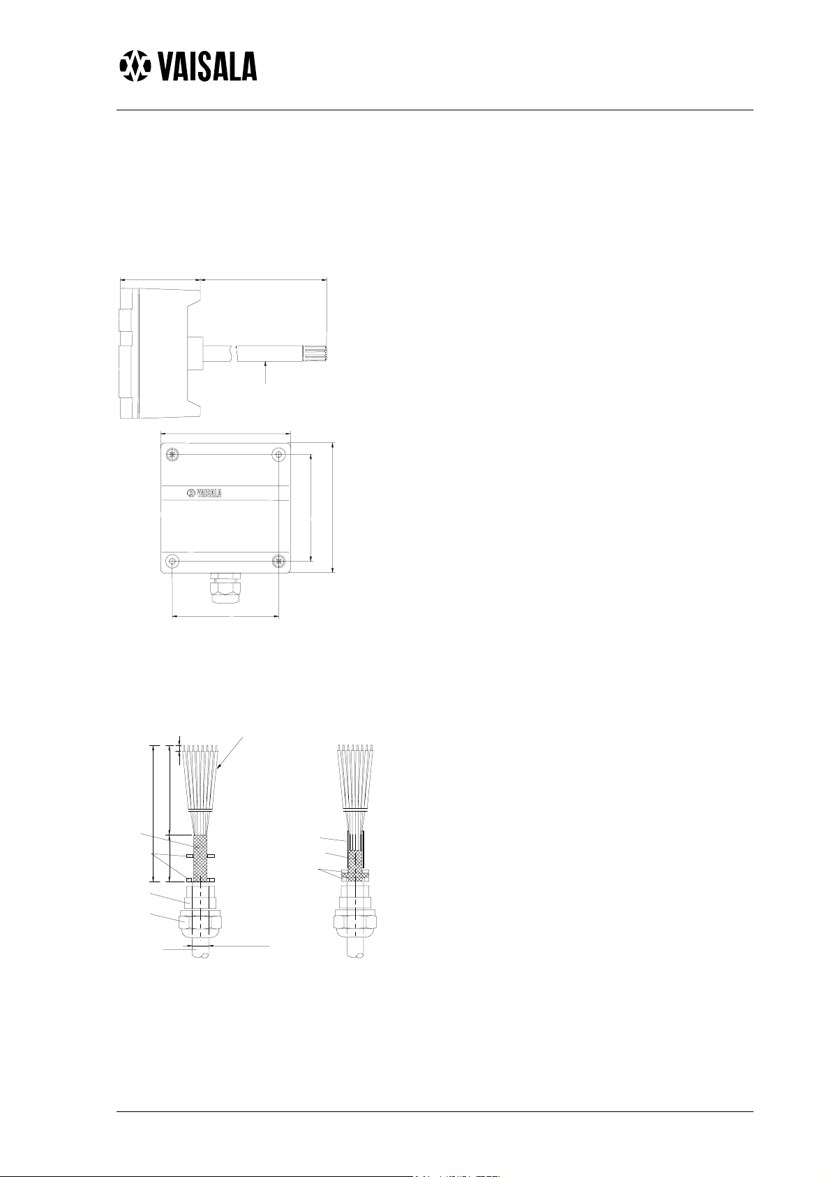
MOUNTING
250 (9.84)62 (2.44)
Ø 12
(0.47)
100 (3.94)
100 (3.94)
Mounting hole 82 (3.23)>>>
Mounting hole 82 (3.23)>>>
Figure 1 Dimensions of the HMD60U/Y
The HMD60U/Y humidity and
temperature transmitters are two-wire
transmitters. They are duct mounted, and
the electronics can be disconnected
without dismantling the installation.
Mount the transmitter with two screws.
Place the drilling template on the duct
surface and drill the holes as indicated.
Remember to drill an additional hole for
calibration purposes. The calibration can
be conveniently performed on site with
the HMI41 or HM70 portable indicator
equipped with an appropriate probe and
optional calibration cable.
GROUNDING
flexible wires 0.5 mm²
(AWG 20), stranded wires
recommended
3
140
165
braid
rubber
ring
brass
disks
nut
cable
25
(If the cable diameter is less
than 7mm, use a shrinking
tube or an adhesive tape)
shielding tube
braid
brass disks
D = Ø 7...10mm
Figure 2 Signal cable grounding with
bushing 18941HM
Open the lid and mount the cable
bushing set 18941HM. Do the grounding
according to Figure 2. When connecting
the signal cable to the transmitter housing,
fold the cable braid between the brass disk
in order to achieve the best EMC performance. Do not leave the bare shield of
the connected wires so that it can
shortcircuit the electronics!
2003-01-22 1
Page 2
HMD60U/Y
Operating Manual HMD60U/Y-M210276en-A
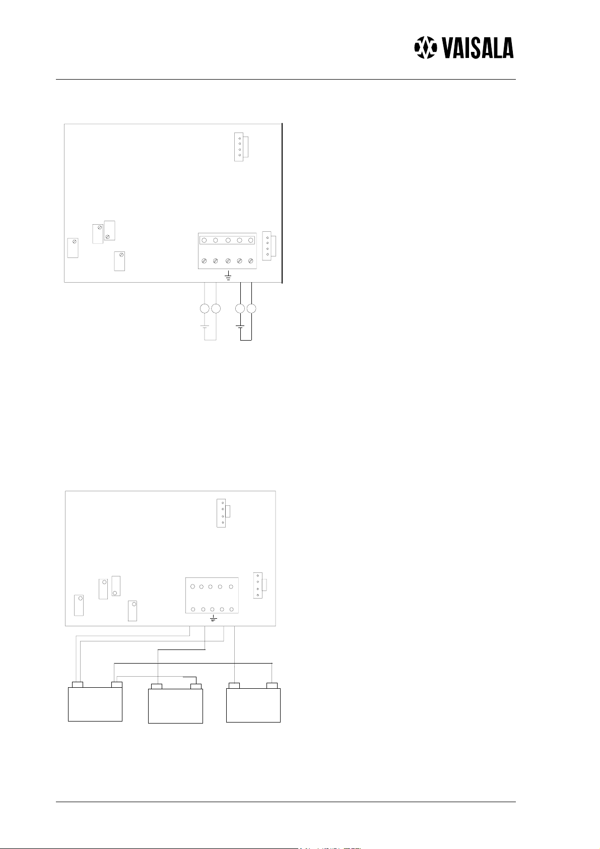
ELECTRICAL CONNECTIONS
RH
TEST
Figure 3a. Electrical
connections.
RH GAIN
RH OFFSET
12 345
T
TEST
T GAIN
T OFFSET
-RH +T+RH -T
+
or
mA
mA
-
+
-
or
mA mA
Signal cables are connected to a removeable 5-pole screw connector. Make the
connections according to Figure 3a above. RH test and T test connectors are used with the
HMI41 or HM70 indicator equipped with an appropriate probe and optional calibration
cable.
Figure 3b shows the same connections in alternative way.
RH TEST
Figure 3b. Electrical
connections.
RH GAIN
RH OFFSET
1 2 3 4 5
T TEST
T OFFSET
+
RH
-
T GAIN
+
POWER SUPPLY
10...35 VDC
------------
+
RH
CHART RECORDER
AMMETER
OR CONTROLL ER
RH+T-T
------------
+
TEMPERATURE
CHART RECORDER
AMMETER
OR CONTROLLER
------------
2 2003-01-22
Page 3

HMD60U/Y
HMD60U/Y-M210276en-A Operating Manual
ELECTRONICS
SCREWS
SPARE PART SENSOR
HUMICAP180
MEMBRANE FILTER
part no. 17039HM
LID
SCREW TERMINAL
10528HM
TO REMOVE THE SENSOR HEAD:
1. Open the lid
2. Disconnect the screw terminal
3. Open the screws (2 pcs)
4. Pull out carefully
TO REINSTALL THE SENSOR HEAD:
1. Push in the sensor head
2. Fasten the screws
3. Connect the screw terminal
4. Close the lid
18941HM
GLANDS
STAINLESS STEEL SINTERED FILTER
part no. HM46670
Electronics (can be disconnected), accessories, spare parts
ONE-POINT RH-CALIBRATION
REPLACEMENT OF THE HUMICAP SENSOR AND THE FILTER
The accuracy is recommended to be
checked at least once a year; the interval
depends on the operating conditions and
the required accuracy of the
measurement. The transmitter calibration
can be conveniently checked with the
HMI41 or HM70 indicator equipped with
Remove the damaged sensor and insert a
new one. Recalibrate the transmitter.
Replace a dirty filter (membrane or
sintered) to ensure a maximum lifetime
and a fast response for the sensor. Do not
attempt to clean the filter.
an appropriate probe and optional
calibration cable. If adjustment is
needed, use the one-point calibration
potentiometer. If you prefer to calibrate
the HMD60U/Y transmitters against
saturated salt solutions, use LiCl (11
%RH) and NaCl (75 %RH) solutions.
2003-01-22 3
Page 4

HMD60U/Y
Operating Manual HMD60U/Y-M210276en-A
TECHNICAL DATA
Relative humidity
Measurement range 0...100 %RH
Output signal
Accuracy at +20 °C
%RH
3
2
1
0
10 4020 605030 8070
0 90 100
-1
-2
-3
Temperature dependence
%RH
2.0
1.5
1.0
0.5
0
-0.5
-1.0
-1.5
-2.0
-20 200
8040 60 ° C10-10 30 50 70
Humidity sensor HUMICAP180
Response time (90%)
at 20 °C in still air 15 s with membrane
filter
Temperature (Y model only)
Measurement range -20...+80 °C
Accuracy
°C
0.8
0.6
0.4
0.2
0
-10
-0.2
-0.4
-0.6
-0.8
0-20 10 20 30 40 50 60 70 80 °C
%RH
Sensor protection:
standard membrane filter
(part no. DRW010525)
option stainless steel sintered
filter
(part no. HM46670)
Connections screw terminals
0.5...1.5 mm
2
Electromagnetic compatibility
The emission and immunity tests have been performed
according to standard EN 61326-1:1997 + Am 1:1998,
Electrical equipment for measurement, control and
laboratory use- EMC requirements; Light
environment.
Emissions:
Test Setup according to Performance
Radiated
interference CISPR16 class B
Immunity:
Test Setup according to
Electrostatic
discharge EN/IEC 61000-4-2
Electrical fast
transients EN/IEC 61000-4-4
RF-radiated
fields EN/IEC 61000-4-3
*GSM-field
immunity ENV50204:1995 criteria A
Linearity better than 0.1 °C
(*additional test)
Temperature sensor Pt 1000 IEC 751 class B
General
Supply voltage 10...35 VDC (RL= 0Ω)
20...35 VDC (RL=500Ω)
Output signal 4...20 mA
Operating temperature range:
electronics -5...+55 °C
sensor head -40...+80 °C
Storage temperature range -40...+80 °C
Housing:
sensor head stainless steel
electronics housing cast aluminium
Cable lead-through:
bushing for 7...10 mm (PG9)
cable (housing IP65 /
NEMA 4),
part no. 18941HM
or armoured cable glands part no. 10528HM
4 2003-01-22
GUARANTEE
Vaisala issues a guarantee for the material and
workmanship of this product under normal operating
conditions for one year from the date of delivery.
Exceptional operating conditions, damage due to
careless handling or misapplication will void the
guarantee.
 Loading...