

Page 1

M211897EN-B
User Guide
Vaisala CARBOCAP
(R)
Carbon Dioxide Probe
GMP252
Page 2

PUBLISHED BY
Vaisala Oyj
Street address: Vanha Nurmijärventie 21, FI-01670 Vantaa, Finland
Mailing address: P.O. Box 26, FI-00421 Helsinki, Finland
Phone: +358 9 8949 1
Fax: +358 9 8949 2227
Visit our Internet pages at www.vaisala.com.
© Vaisala 2016
No part of this manual may be reproduced,
published or publicly displayed in any form
or by any means, electronic or mechanical
(including photocopying), nor may its
contents be modified, translated, adapted,
sold or disclosed to a third party without
prior written permission of the copyright
holder. Translated manuals and translated
portions of multilingual documents are
based on the original English versions. In
ambiguous cases, the English versions are
applicable, not the translations.
The contents of this manual are subject to
change without prior notice.
Local rules and regulations may vary and
they shall take precedence over the
information contained in this manual.
Vaisala makes no representations on this
manual’s compliance with the local rules
and regulations applicable at any given
time, and hereby disclaims any and all
responsibilities related thereto.
This manual does not create any legally
binding obligations for Vaisala towards
customers or end users. All legally binding
obligations and agreements are included
exclusively in the applicable supply
contract or the General Conditions of Sale
and General Conditions of Service of
Vaisala.
This product contains software developed
by Vaisala or third parties. Use of the
software is governed by license terms and
conditions included in the applicable
supply contract or, in the absence of
separate license terms and conditions, by
the General License Conditions of Vaisala
Group.
Page 3

Table of Contents
1. About This Document........................................................................................ 7
1.1. Documentation Conventions................................................................................ 7
1.2. Version Information............................................................................................... 7
1.3. Related Manuals..................................................................................................... 8
1.4. Trademarks............................................................................................................. 8
1.5. Patent Notice..........................................................................................................8
2. Product Overview................................................................................................9
2.1. Introduction to GMP252 .......................................................................................9
2.2. Basic Features and Options................................................................................10
2.3. Operating Principle of CO2 Measurement.......................................................... 11
2.4. Environmental Compensation.............................................................................12
2.4.1. Temperature Compensation......................................................................... 13
2.4.2. Pressure Compensation.................................................................................13
2.4.3. Background Gas Compensation...................................................................13
2.5. Probe Startup........................................................................................................14
2.6. Analog Output Overrange Behavior..................................................................14
2.6.1. Analog Output Overrange Example............................................................ 15
2.7. Safety.....................................................................................................................16
2.7.1. ESD Protection............................................................................................... 16
2.8. Regulatory Compliances......................................................................................16
3. Installation.............................................................................................................17
3.1. GMP252 Probe Dimensions................................................................................. 17
3.2. Recommended Installation..................................................................................17
3.3. Installation Accessories........................................................................................17
3.3.1. 243261SP Installation Flange........................................................................ 18
3.3.2. 243257SP Mounting Clips............................................................................. 19
3.4. Power Supply........................................................................................................19
3.5. Wiring................................................................................................................... 20
4. Vaisala Industrial Protocol..............................................................................21
4.1. Overview................................................................................................................ 21
4.2. Serial Interface Settings.......................................................................................21
4.3. Physical Interface..................................................................................................21
4.4. Connecting with a Computer............................................................................. 22
4.4.1. Installing the Driver for the USB Service Cable......................................... 23
4.5. Accessing Serial Commands from Modbus or Analog Mode......................... 23
4.6. Enabling Modbus Mode from Vaisala Industrial Protocol...............................24
4.7. Changing From Digital Output to Analog Output........................................... 25
4.8. Serial Commands.................................................................................................25
4.9. Device Information and Status...........................................................................28
4.10. Serial Line Output and Communication.............................................................31
4.11. Analog Output..................................................................................................... 39
4.12. Calibration and Adjustment...............................................................................44
4.13. Environmental Compensation Commands...................................................... 48
4.14. Other Commands................................................................................................ 55
5. Modbus...................................................................................................................57
1
Page 4

GMP252 User Guide M211897EN-B
6. Operating with MI70 Indicator.................................................................... 58
6.1. Overview of MI70 Support................................................................................. 58
6.2. Basic Display........................................................................................................ 58
6.3. Graphical Display.................................................................................................59
6.4. Main Menu............................................................................................................ 59
6.5. Connecting Probe to MI70 Indicator................................................................. 59
6.6. MI70 Indicator Parts............................................................................................60
6.7. Holding and Saving the Display........................................................................ 60
6.8. Recording Data.....................................................................................................61
6.9. Changing Environmental Compensation Settings with MI70 Indicator........62
6.10. Calibration and Adjustment with MI70 Indicator............................................ 63
6.10.1. 1-Point Adjustment with an MI70-Compatible Reference Probe............ 63
6.10.2. 1-Point Adjustment with a Reference Gas................................................. 64
7. Maintenance.........................................................................................................67
7.1. Cleaning................................................................................................................ 67
7.1.1. Chemical Tolerance....................................................................................... 67
7.2. Changing the Filter..............................................................................................68
7.3. Calibration and Adjustment............................................................................... 68
7.3.1. Calibration Setup.......................................................................................... 69
7.3.2.
Eect of Environmental Compensations...................................................69
7.3.3. Limits of Adjustment....................................................................................70
7.3.4. Adjustment Types.........................................................................................70
7.3.5. DRW244827SP Calibration Adapter............................................................71
8. Troubleshooting................................................................................................. 72
8.1. Problem Situations.............................................................................................. 72
8.2. Error Messages.....................................................................................................72
8.3. Analog Output Error State..................................................................................74
9. Technical Data.....................................................................................................75
9.1. GMP252
Specifications........................................................................................75
9.2. Spare Parts and Accessories.............................................................................. 78
9.3. GMP252 Probe Dimensions................................................................................ 78
9.4. 243261SP Mounting Flange Dimensions........................................................... 79
9.5. 243261SP Calibration Adapter Dimensions......................................................80
Appendix A:
Modbus Reference..........................................................................81
A.1. Function Codes..................................................................................................... 81
A.2. Modbus Registers................................................................................................. 81
A.2.1. Measurement Data......................................................................................... 81
A.2.2. Configuration Registers................................................................................82
A.2.3. Status Registers............................................................................................ 84
A.2.4. Device Identification Objects...................................................................... 84
A.3. Modbus Communication Examples...................................................................86
A.4. Filtering Factor.....................................................................................................88
Technical Support
........................................................................................................... 89
Warranty...........................................................................................................................89
Recycling..........................................................................................................................89
2
Page 5

List of Figures
Figure 1 GMP252 Probe Parts........................................................................................... 9
Figure 2 Probe Cuvette with Mirror and Sensor Chips...............................................11
Figure 3 CO2 Measurement in the Measurement Cuvette....................................... 12
Figure 4 Example of Analog Output Overrange Behavior ......................................15
Figure 5 GMP252 Dimensions.......................................................................................... 17
Figure 6 Probe with 243261SP Installation Flange..................................................... 18
Figure 7 Probe in 243257SP Mounting Clips................................................................19
Figure 8 Example of analog output overrange behavior........................................ 43
Figure 9 MI70 Basic Display.............................................................................................58
Figure 10 MI70 Indicator Parts......................................................................................... 60
Figure 11 CO2 Reading with Tcomp and Pcomp on MI70 Screen.......................... 62
Figure 12 Probe Compensation Settings on MI70 Screen.........................................62
Figure 13 Opening the Filter............................................................................................. 68
Figure 14 DRW244827SP Calibration Adapter with Probe Inserted.......................71
Figure 15 GMP252 Dimensions......................................................................................... 78
Figure 16 243261SP Mounting Flange Dimensions..................................................... 79
Figure 17 243261SP Mounting Flange Dimensions, Cross Section......................... 79
Figure 18 243261SP Calibration Adapter Dimensions................................................80
3
Page 6

GMP252 User Guide M211897EN-B
List of Tables
Table 1 Document Versions.............................................................................................. 7
Table 2 Related Documents.............................................................................................. 8
Table 3 Applicable Patents................................................................................................8
Table 4 Analog Output Overrange Clipping and Error Limits................................14
Table 5 M12 Male Connector...........................................................................................20
Table 6 Default Serial Interface Settings......................................................................21
Table 7 Basic Serial Commands.....................................................................................26
Table 8 Advanced Serial Commands............................................................................27
Table 9 ? Command.......................................................................................................... 28
Table 10 Errs Command.....................................................................................................28
Table 11 Help Command................................................................................................... 29
Table 12 Snum command.................................................................................................. 29
Table 13 System Command.............................................................................................. 30
Table 14 Time Command...................................................................................................30
Table 15 Vers Command....................................................................................................30
Table 16 Addr Command....................................................................................................31
Table 17 Close Command................................................................................................... 31
Table 18 Form Command................................................................................................... 31
Table 19 Output Parameters for Form Command...................................................... 33
Table 20 Modifiers for Form Command.........................................................................34
Table 21 Intv Command..................................................................................................... 35
Table 22 Open Command.................................................................................................. 35
Table 23 R Command..........................................................................................................36
Table 24 S Command..........................................................................................................36
Table 25 Sdelay Command............................................................................................... 36
Table 26 Send Command................................................................................................... 37
Table 27 Seri Command..................................................................................................... 37
Table 28 Smode Command............................................................................................... 38
Table 29 Amode Command.............................................................................................. 39
Table 30 Aover Command................................................................................................ 40
Table 31 Asel Command.................................................................................................... 43
Table 32 Adate Command................................................................................................ 44
Table 33 Atext Command..................................................................................................45
Table 34 Cdate Command.................................................................................................45
Table 35 Ctext Command..................................................................................................45
Table 36 CCO2 Command................................................................................................. 46
Table 37 Env Command.....................................................................................................49
Table 38 O2cmode Command...........................................................................................51
Table 39 Pcmode Command.............................................................................................52
Table 40 Rhcmode Command.......................................................................................... 53
Table 41 Tcmode Command.............................................................................................54
Table 42 Frestore Command.............................................................................................55
Table 43 Pass Command....................................................................................................55
Table 44 Reset Command................................................................................................. 56
Table 45 Default Modbus Serial Communication Settings....................................... 57
Table 46 Performance.........................................................................................................75
Table 47 Operating Environment.................................................................................... 76
Table 48 Inputs and Outputs.............................................................................................77
Table 49 Mechanics............................................................................................................. 77
Table 50 Supported Function Codes...............................................................................81
4
Page 7

Table 51 Modbus Measurement Data Registers (Read-Only)..................................81
Table 52 Modbus Configuration Data Registers (Writable).....................................82
Table 53 Modbus Status Registers (Read-Only).........................................................84
Table 54 Device Identification Objects.......................................................................... 84
5
Page 8

GMP252 User Guide M211897EN-B
6
Page 9

1. About This Document
1.1. Documentation Conventions
Chapter 1 – About This Document
DANGER!
carefully at this point, death will follow.
WARNING!
carefully at this point, there is a risk of injury or even death.
CAUTION!
carefully at this point, the product could be damaged or important data could be lost.
Note highlights important information on using the product.
Tip gives information for using the product more eciently.
alerts you to a fatal hazard. If you do not read and follow instructions
alerts you to a serious hazard. If you do not read and follow instructions
warns you of a potential hazard. If you do not read and follow instructions
1.2. Version Information
Table 1 Document Versions
Document Code Date Description
M211897EN-B August 2016 Modbus status register values and
descriptions updated.
M211897EN-A May 2016 First version.
7
Page 10

GMP252 User Guide M211897EN-B
1.3. Related Manuals
Table 2 Related Documents
Document Code Description
M211893EN
M211799EN
M211798EN
Vaisala CARBOCAP
GMP252 Quick Guide
Vaisala CARBOCAP
User Guide
Vaisala CARBOCAP
Quick Guide
(R)
Carbon Dioxide Probe
(R)
Carbon Dioxide Probe GMP251
(R)
Carbon Dioxide Probe GMP251
1.4. Trademarks
Vaisala
Windows
(R)
and CARBOCAP
(R)
is either a registered trademark or trademark of Microsoft Corporation in the
United States and other countries.
All other product or company names that may be mentioned in this publication are trade
names, trademarks, or registered trademarks of their respective owners.
(R)
are registered trademarks of Vaisala Oyj.
1.5. Patent Notice
This product is protected by the following patents and their corresponding national rights:
Table 3 Applicable Patents
Patent Issued By Patent Number
United States Patent and Trademark Oce US 5,827,438
US 6,177,673
European Patent Oce EP0776023
EP0922972
German Patent and Trade Mark Oce 69615635
Japan Patent Oce 4263285
Finnish Patent Oce 112005
105598
8
Page 11

1
2 3 4 5
Chapter 2 – Product Overview
2. Product Overview
2.1. Introduction to GMP252
GMP252 is designed for CO2 measurement in demanding applications that require reliable
and accurate performance. The measurement range is 0 ... 10 000 ppmCO2 (measurements
can be carried out in the 10 000 ... 30 000 ppmCO2 range with reduced accuracy).
The probe is based on Vaisala’s patented 2nd generation CARBOCAP
equipped with Vaisala's Microglow infrared light source. The probe is easy to install with a
plug-in/plug-out M12 connection.
GMP252 is able to compensate for temperature, pressure and background gas. For
temperature compensation purposes, the probe includes an internal temperature sensor
that allows measurement compensation according to ambient temperature. As dust and
most chemicals do not
background gas can be compensated for, GMP252 can provide accurate and stable
measurements in a wide range of applications.
aect the measurement, and the eect of temperature, pressure and
(R)
technology and
Figure 1 GMP252 Probe Parts
1 5-pin M12 connector. For pinout, see 3.5. Wiring (page 20).
2 Probe name and orientation mark for Vaisala transmitter installations (front) and laser-
printed type label (back).
3 Probe body. Contains the main component board.
4
Measurement cuvette with optics and CARBOCAP
5 Filter (sintered, PTFE)
CAUTION!
inside the probe body.
Do not attempt to open the probe body. There are no user serviceable parts
(R)
CO2 sensor.
9
Page 12

GMP252 User Guide M211897EN-B
2.2. Basic Features and Options
• CO2 measurement range 0 ... 10 000 ppmCO2.
• Measurement up to 30 000 ppmCO2 with reduced accuracy.
• Operating temperature range -40…+60 °C (-40...140 ºF).
(R)
• Vaisala CARBOCAP
• Measurement compensated for
The temperature compensation can be based on an integrated temperature sensor or
use a set temperature. Pressure and background gas parameters can be set to the
probe.
• Heating to avoid condensation on optical elements.
• Digital output with RS-485:
• Modbus RTU
• Vaisala Industrial Protocol
• Analog output:
• Current output (0 ... 20 mA or 4 ... 20 mA)
• Voltage output (0 ... 5 V or 0...10 V)
• Compatible with MI70 hand-held meter.
• Easy plug-in, plug-out.
CO2 sensor with excellent long-term stability.
eects of temperature, pressure, and background gas.
More Information
‣
GMP252
‣
Operating Principle of CO2 Measurement (page 11)
‣
Environmental Compensation (page 12)
‣
Modbus (page 57)
‣
Overview of MI70 Support (page 58)
Specifications (page 75)
10
Page 13

1
2
3
Chapter 2 – Product Overview
2.3. Operating Principle of CO
Measurement
The Vaisala CARBOCAP
probe is a silicon-based, nondispersive
infrared (NDIR) sensor for the measurement
of gaseous carbon dioxide in air-like gases.
Figure 2 Probe Cuvette with Mirror and Sensor
Chips
1 Mirror
2 Cuvette
3 Sensor chips under TO5 package
2
(R)
sensor used in the
The sensitivity to carbon dioxide is based on absorption of infrared light at a characteristic
wavelength. During measurement, infrared light is routed through the cuvette that contains
the gas to be measured. A mirror
that measures the light intensity at a wavelength determined by a Fabry–Pérot
interferometer (FPI) and a band pass
The carbon dioxide measurement consists of two steps: first, the FPI is electrically tuned so
that its pass band coincides with the characteristic absorption wavelength of carbon dioxide
and the signal is recorded. Second, the pass band is shifted to a wavelength where no
absorption occurs in order to get a reference signal. The ratio of these two signals, one at
the absorption wavelength and the other at the reference wavelength, gives the fraction of
light absorption from which the carbon dioxide concentration is calculated. Measuring the
reference signal compensates the possible
due to dirt on optical surfaces, making the sensor very stable over time.
TO5 packages with hermetic windows are used to protect the sensor chips from moisture
and contamination. A heater chip is utilized to prevent condensation in normal operation.
reflects the light from the cuvette to a thermopile detector
filter.
eects of sensor aging and signal attenuation
11
Page 14

1
2
3
4
6
7
5
GMP252 User Guide M211897EN-B
Figure 3 CO
Measurement Cuvette
1 Gold-plated mirror
2 Light absorbed by CO2 in the measured
gas
3 Hermetic window
4 Fabry-Perot interferometer
5 Light source (Microglow)
6 Hermetic window
7 Thermopile detector
Measurement in the
2
2.4. Environmental Compensation
When necessary, various environmental compensations can be applied to improve the CO
measurement accuracy of the probe.
The probe can compensate for the eects of the following parameters:
• Temperature
• Pressure
• Background gas oxygen (O2) content
• Background gas relative humidity (%RH)
The probe has an on-board temperature sensor that can be used to compensate for
temperature. Additionally, if the probe is integrated in a system that measures one or more
of the compensation parameters (T, P, RH, O2), they can be updated to the probe
continuously.
To apply an accurate relative humidity compensation, make sure that also the temperature
compensation and pressure compensation
environment.
configurations match the measurement
2
12
Page 15

Chapter 2 – Product Overview
Compensation parameters are configured on the order form when ordering the probe, and
can later be updated using Vaisala Industrial Protocol or Modbus protocol.
You can also turn o any of the compensations. In that case, the probe uses the default
compensation value that is mathematically neutral for the probe’s internal compensation
model.
2.4.1. Temperature Compensation
The probe can measure the approximate temperature of the CARBOCAP
compensation, or use a
fixed setpoint. The temperature measurement is accurate enough to
(R)
sensor for
be useful for compensation, and is recommended for use unless a dedicated temperature
measurement is available and can be regularly updated to the probe. If the measurement is
made in a constant temperature, this
fixed temperature setpoint can be set as the
compensation value.
If temperature compensation is turned o, the probe uses the default value of +25 °C
(+77 °F).
When the probe is installed through a
outside the measuring environment, it is possible that temperature conduction from the
probe body and cable outside the measurement environment aects the temperature
compensation and decreases measurement accuracy.
flange and part of the probe and the cable is left
2.4.2. Pressure Compensation
The probe does not have on-board pressure measurement. However, a pressure reading
from an external source can be used as a setpoint value for compensation using Vaisala
Industrial Protocol or Modbus.
If pressure compensation is turned o, the probe uses the default compensation value of
1013 hPa.
2.4.3. Background Gas Compensation
The probe does not have on-board oxygen or relative humidity measurement. However,
oxygen and relative humidity readings from an external source can be used as setpoint
values for compensation using Vaisala Industrial Protocol or Modbus. The default setpoint
values are as follows:
• Oxygen concentration: 0 %O2 or 21 %O
• Relative humidity: 0 %RH or 50 %RH
If background gas compensations are turned
In practice, when CO2 is measured at a ppm level, O2 and RH compensations have a very
eect on the accuracy of the measurement.
small
2
o, the probe uses the value 0 % for both.
13
Page 16

GMP252 User Guide M211897EN-B
2.5. Probe Startup
When powered on, the probe starts up within 12 seconds. Measurements from the outputs
(digital and analog) become available during this time but note that they will only reach
specified accuracy after a 2-minute warm-up period. For this reason, you should design your
system so that it does not rely on measurements from the probe during this time. When the
probe is in analog output mode, the probe remains in an error state during the start-up
phase until measurement output becomes available.
Specifically note that the CO2 reading will rise to the correct reading as the sensor’s
infrared emitter achieves operation temperature.
2.6. Analog Output Overrange Behavior
Analog output of the probe has a defined behavior when the values measured by the probe
are outside the scaled analog output range. At first, the output is clipped when the
measurement exceeds a set limit (the measurement continues, but the output does not
change from the clipped value).
When the measurement exceeds the second limit (error limit), the analog output switches to
the error state
defined for the output. The table below lists the clipping and error limits and
default error state outputs for the analog voltage and current outputs.
Table 4 Analog Output Overrange Clipping and Error Limits
Output voltage / current Clipping Limit Error Limit Default Error State Output
0 ... 5 V >5 % >10 % 0 V
0 ... 10 V >1 % >10 % 0 V
0 ... 20 mA >5 % >10 % 23 mA
4 ... 20 mA >5 % >10 % 2 mA
The same clipping and error limits are applied when the measured value drops back to the
scaled range: at
first the output returns to the clipped value from the error state, and then to
normal output.
Clipping and error state limits
the limits are 1 % and 10 %, and for 0 ... 5 V output the limits are 5 % and 10 %.
dier for 0 ... 10 V and 0 ... 5 V outputs. For 0 ... 10 V output
14
Page 17

More Information
Output
voltage (V)
Time
0.00
In error state at
>2200 ppm
(2000 ppm + 10%)
5.00
5.25
Clipped at
2100 ppm
(2000 ppm + 5%)
Regular
measurement
Output clipping limit
Error level
‣
Analog Output Error State (page 74)
2.6.1. Analog Output Overrange Example
Consider a probe with 0 ... 5 V output, scaled to 0 ... 2000 ppmCO2.
Chapter 2 – Product Overview
• When the measured CO
rises above 2000 ppmCO2, the output rises above 5 V.
2
• The output keeps rising until the measurement is 2100 ppmCO2, at which point the
probe outputs 5.25 V.
• If the CO2 level rises above 2100 ppmCO2, the output still remains at 5.25 V.
• If the CO2 level rises above 2200 ppmCO2, the output enters the error state, which is 0
V for the 0 ... 5 V output.
Figure 4 Example of Analog Output Overrange Behavior
This example uses output scaled to 0 ... 5 V and 0 ...2000 ppmCO2, error level set to 0 V,
clipping set to 5 % overrange, and error limit set to 10 % overrange. CO2 concentrations
(ppm) are indicated for the clipping point and error limit point.
This overrange and error behavior is
readings of the digital outputs.
You can change the analog output overrange behavior using the aover command.
specific to the analog output, and does not aect the
15
Page 18

GMP252 User Guide M211897EN-B
2.7. Safety
The probe delivered to you has been tested for safety and approved as shipped from the
factory. Note the following precautions:
WARNING!
been exposed to dangerous contamination, and is safe to handle without special
precautions.
CAUTION!
lead to malfunction.
CAUTION!
inside the probe body.
When returning a product for calibration or repair, make sure it has not
Do not modify the unit. Improper modification can damage the product or
Do not attempt to open the probe body. There are no user serviceable parts
2.7.1. ESD Protection
Electrostatic Discharge (ESD) can cause immediate or latent damage to electronic circuits.
Vaisala products are adequately protected against ESD for their intended use. However, it is
possible to damage the product by delivering electrostatic discharges when touching an
exposed contact on the product.
To make sure you are not delivering high static voltages yourself, avoid touching the pins on
the M12 connector.
2.8. Regulatory Compliances
The probe is in conformity with the provisions of the following EU directives:
• RoHS Directive
• EMC Directive
Conformity is shown by compliance with the following standards:
• EN 50581: Technical documentation for the assessment of electrical and electronic
products with respect to the restriction of hazardous substances.
• EN 61326-1: Electrical equipment for measurement, control, and laboratory use – EMC
requirements – Generic environment.
• EN 55022: Information technology equipment – Radio disturbance characteristics –
Limits and methods of measurement.
16
Page 19

3. Installation
12 mm 76 mm 42 mm
130 mm, Ø 25 mm
3.1. GMP252 Probe Dimensions
The dimensions are given in millimeters (mm).
Chapter 3 – Installation
Figure 5 GMP252 Dimensions
3.2. Recommended Installation
The probe can be installed in an environment with an operating temperature range -40 ...
+60 °C (-40 ... +140 °F). Make sure the probe is in a location that represents the
measurement environment properly.
The 5-pin male M12 connector on the probe provides an easy plug-in/plug-out connection to
a compatible cable.
3.3. Installation Accessories
The probe can be installed through a surface using the optional
product code 243261SP, or attached for example to a wall with the optional clip accessory
(two-clip set, Vaisala product code 243257SP.
More Information
‣
Spare Parts and Accessories (page 78)
flange accessory (Vaisala
17
Page 20
1
2
3
GMP252 User Guide M211897EN-B
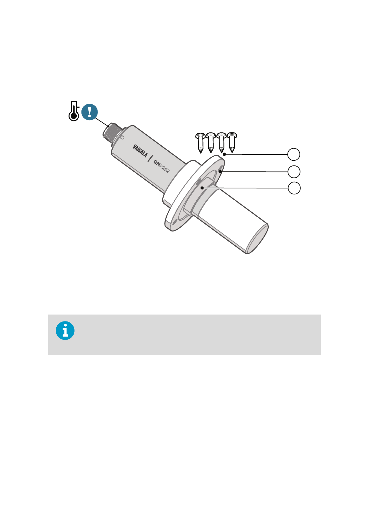
3.3.1. 243261SP Installation Flange
The optional flange accessory is used to install the probe body through a wall or other
surface.
Figure 6 Probe with 243261SP Installation Flange
1 4 Phillips head screws (included)
2 Installation flange (diameter 60 mm) with four Ø 4.2 mm screw holes
3 Gasket ring
Leaving part of the probe body and the cable outside the measurement environment can
cause heat conduction that aects the temperature compensation and measurement
accuracy.
More Information
‣
243261SP Mounting Flange Dimensions (page 79)
18
Page 21

Ø 4.2 mm
Chapter 3 – Installation
3.3.2. 243257SP Mounting Clips
The optional mounting clips (set of two clips) are used to hold the probe in place for
example on a wall or other surface. Each clip base attaches to the installation surface with
one screw (screw hole Ø 4.2 mm).
Figure 7 Probe in 243257SP Mounting Clips
3.4. Power Supply
The supply voltage range of the probe is 12 ... 30 VDC with the digital output option. If the
analog output is used, the supply voltage range is 12 ... 30 VDC for voltage output and
20 ... 30 VDC for current output.
Typical power consumption is less than 0.4 W in continuous operation, and the maximum is
0.5 W.
19
Page 22

1
5
3
4
2
GMP252 User Guide M211897EN-B
3.5. Wiring
Table 5 M12 Male Connector
Pin# Function Note Cable 223263SP
Wire Colors
1 Power in • With digital output: 12 ... 30 VDC
• With voltage output: 12 ... 30 VDC
• With current output: 20 ... 30 VDC
Typical average power consumption <0.4 W, maximum
0.5 W.
2 RS-485-
or voltage
output
3 GND – Blue
4 RS-485 +
or current
output
5 Output control Connecting pin #5 to GND (pin #3) forces the probe to
Voltage:
0 ... 5 VDC or 0 ... 10 VDC (default analog output scaling)
Current:
0 … 20 mA or 4 ... 20 mA (default analog output scaling)
analog output mode. If an analog output configuration
has not been selected, default 0...10 VDC and 4...20 mA
scalings are used.
If pin #5 is not connected, the analog or digital output
selected when ordering or set later through
configuration is used.
Brown
White
Black
Gray
20
Note that the probe always remains in analog mode when pin #5 is connected to pin #3,
and cannot be switched to digital output in this wiring option.
Page 23

Chapter 4 – Vaisala Industrial Protocol
4. Vaisala Industrial Protocol
4.1. Overview
RS-485 line of the probe provides an implementation of the Vaisala Industrial Protocol that
can be used for service and configuration use, or for interfacing with the system to which
the probe is integrated. The protocol is a plaintext protocol suitable for use both by human
operators and automated systems.
4.2. Serial Interface Settings
Table 6 Default Serial Interface Settings
Property Description/Value
Bit rate 19200
Parity None
Data bits 8
Stop bit 1
Flow control None
4.3. Physical Interface
The physical interface is a non-isolated 2-wire interface. The data lines are RS-485 D- and
RS-485 D+. Ground is shared with power supply. The connector is a 5-pin male M12.
More Information
‣
Wiring (page 20)
21
Page 24

GMP252 User Guide M211897EN-B
4.4. Connecting with a Computer
• Vaisala USB service cable (order code 242659)
• Computer with:
• Windows operating system
• Terminal application (for example PuTTy, available from www.vaisala.com/
software)
• Free USB port
• Driver for Vaisala USB service cable installed (available on the cable installation
media and at www.vaisala.com/software)
The steps below describe how to connect to the probe using the PuTTY terminal application
for Windows and a USB computer connection cable. Connecting with a computer allows you
to
configure and troubleshoot your probe using serial line commands.
1. If you have not used the Vaisala USB cable before, install the driver before attempting
to use the cable.
2. Connect the USB serial interface cable between your computer and the M12 connector
of the probe.
3. Start the PuTTY application.
4. Select Connection > Serial & USB and check that the correct COM port is selected in
the Serial or USB line to connect to
field. If you are using the PuTTY terminal
application supplied by Vaisala, you can press the USB Finder button to open the
Vaisala USB Instrument Finder program.
5. Check that the other serial settings are correct for your connection, and change if
necessary. Flow control should be set to None unless you have a reason to change it.
22
Page 25

Chapter 4 – Vaisala Industrial Protocol
6. Select Terminal. Use the following settings:
• Local Echo
Select Force on. This setting ensures that your typing is shown on the session
window.
• Send line ends with line feeds (CR+LF)
Set to Selected. This setting ensures that all text lines remain visible on the
session window.
7. To open the connection window and start using the serial line, select Open.
If PuTTY is unable to open the serial port you selected, it shows you an error message
instead. If this happens, restart PuTTY and check the settings.
More Information
‣
Serial Interface Settings (page 21)
‣
Installing the Driver for the USB Service Cable (page 23)
4.4.1. Installing the Driver for the USB Service Cable
Before taking the USB service cable into use for the
USB driver on your computer (requires Windows). When installing the driver, you must
accept any security prompts that may appear.
1. Check that the USB service cable is not connected. Disconnect the cable if you have
already connected it.
2. Insert the media that came with the cable, or download the latest driver from
www.vaisala.com/software.
3. Run the USB driver installation program (setup.exe), and accept the installation
defaults. The installation of the driver may take several minutes.
4. After the driver has been installed, connect the USB service cable to a USB port on your
computer. Windows will detect the new device, and use the driver automatically.
5. The installation has reserved a COM port for the cable. Verify the port number, and the
status of the cable, using the Vaisala USB Instrument Finder program that has been
installed in the Windows Start menu. Windows will recognize each individual service
cable as a
port in the settings of your terminal program.
dierent device, and reserve a new COM port. Remember to use the correct
first time, you must install the provided
4.5. Accessing Serial Commands from Modbus or Analog Mode
1. Connect the USB cable to your PC and start the terminal application as instructed in
4.4. Connecting with a Computer (page 22).
23
Page 26

GMP252 User Guide M211897EN-B
2. Start a new terminal session using the default serial settings.
3. Keep the Enter key pressed down and connect the probe to the USB cable. When the
probe is powered on (connected to your PC with the USB cable), you must send five
carriage returns (Enter key presses) within 0.7 seconds to force the probe to serial
command mode. The probe model information appears in the terminal application
when the mode has been succesfully changed, and Vaisala Industrial Protocol
commands are available for use.
4. To test the connection, enter for example the ? command. If the mode change failed,
close the terminal application, disconnect the probe from the USB cable, and repeat
step 2 and step 3.
5. To keep the serial mode in use (forced serial mode access is temporary and switches
at reset), select a serial output option (stop/run/poll) with the smode command.
Note that the probe always remains in analog mode when pin #5 is connected to pin #3,
and cannot be switched to digital output in this wiring option.
More Information
‣
Serial Interface Settings (page 21)
‣
Enabling Modbus Mode from Vaisala Industrial Protocol (page 24)
4.6. Enabling Modbus Mode from Vaisala Industrial Protocol
If you need to switch from Vaisala Industrial Protocol to Modbus mode, you must
the following settings:
• Serial line operating mode
• Modbus address
• Serial line settings (bit rate, parity, stop and data bits)
configure
o
1. Connect the USB cable to your PC and start the terminal application as instructed in
4.4. Connecting with a Computer (page 22).
2. Set the serial mode to Modbus with the smode command:
smode modbus
24
Page 27

Chapter 4 – Vaisala Industrial Protocol
3. Set the Modbus address to 240 with the addr command:
addr 240
4. Set the serial line settings to 19200/N/8/2 with the seri command:
seri 19200 N 8 2
5. Power
configuration is available at the next restart.
More Information
‣
Accessing Serial Commands from Modbus or Analog Mode (page 23)
o (disconnect) the probe or reset with the reset command. The new
4.7. Changing From Digital Output to Analog Output
1. Set up a terminal connection as instructed in 4.4. Connecting with a Computer
(page 22).
2. Change the mode from digital to analog with the smode serial command: smode
analog.
3. Reset the probe (disconnect and reconnect the cable or use the reset serial command)
to power on in analog output mode.
More Information
‣
Accessing Serial Commands from Modbus or Analog Mode (page 23)
4.8. Serial Commands
The notation <cr> refers to the carriage return control character, which you can send in a
terminal application by pressing enter on your keyboard. Before entering commands, send a
<cr> to clear the command
You can enter the commands in uppercase or lowercase. In the command examples, the
keyboard input by the user is in bold type.
Table 7 (page 26) lists the basic serial commands that are available by default. To access
advanced serial commands (listed in Table 8 (page 27)), enter the command pass 1300.
buer.
25
Page 28

GMP252 User Guide M211897EN-B
Table 7 Basic Serial Commands
Command Description
Device information and status
?
??
errs
help
snum
system
time
vers
Serial line output and communication
close
form [modifier string]
intv [0 ... 255 s/min/h]
open [address]
Show probe information.
Show probe information (will respond in POLL mode).
Show currently active errors.
Show list of currently available serial commands.
Show probe serial number.
Show probe firmware information.
Show probe operation hours and uptime.
Show probe firmware version.
Close connection to probe (POLL mode)
Show or set output format.
Set continuous output interval for R command.
Open connection to probe in POLL mode.
r
s
sdelay [0 ... 255]
send
seri [baud data stop
parity]
smode [mode]
Environmental compensation
env
Adjustment information
adate
atext
Other commands
Start the continuous outputting.
Stop the continuous outputting.
Show or set serial line transmission delay in milliseconds.
Output a single measurement message.
Show or set the serial interface settings.
Show or set startup serial mode: RUN, STOP, or POLL.
Show or set environmental parameters.
Show CO2 factory adjustment date.
Show CO2 factory adjustment information.
26
Page 29

Command Description
Chapter 4 – Vaisala Industrial Protocol
reset
pass [1300]
Reset the probe.
Access advanced serial commands.
Table 8 Advanced Serial Commands
Command Description
Serial line output and communication
addr [0 … 254] Show or set probe address.
Analog output
amode
aover
asel
Calibration and adjustment
cco2
Show or set analog output mode (analog output limits and error level).
Show or set analog output overrange and clipping behavior.
Show or set analog output parameter and scaling.
Adjust CO2 measurement gain and oset.
cdate
ct
ctext
Environmental compensation
o2cmode
pcmode
rhcmode
tcmode
Other commands
frestore
Show or set calibration date.
Adjust temperature measurement oset.
Show or set calibration information.
Show or set oxygen compensation mode.
Show or set pressure compensation mode.
Show or set humidity compensation mode.
Show or set temperature compensation mode.
Restore probe to factory settings.
27
Page 30

GMP252 User Guide M211897EN-B
4.9. Device Information and Status
Table 9 ? Command
Syntax Description
?<cr>
??<cr>
Example:
?
Device : GMP25x
Copyright : Copyright (c) Vaisala Oyj 2016. All rights
reserved.
SW Name : GMP25x
SW version : 1.0.0
SNUM : GMP233_5_18
SSNUM : S1234567
CBNUM : c1234567
Calibrated : 20160504 @ Vaisala/R&D
Address : 0
Smode : STOP
Show listing of device information.
Show listing of device information even if device is in
poll mode and connection has not been opened
using the open command.
Table 10 Errs Command
Syntax Description
errs<cr>
Example (no active errors):
errs
NO CRITICAL ERRORS
NO ERRORS
NO WARNINGS
STATUS NORMAL
28
Show active error(s). For a list of possible errors and
their remedies, see 8.2. Error Messages (page 72).
Page 31

Table 11 Help Command
Syntax Description
Chapter 4 – Vaisala Industrial Protocol
help<cr>
Example (showing a list of the basic commands):
help
ADATE
ADDR
ATEXT
CLOSE
ENV
ERRS
FORM
HELP
INTV
PASS
RR
ESET
RX
SDELAY
SEND
SENDX
SERI
SMODE
SNUM
SYSTEM
UNIQID
TIME
VERS
Show list of currently available serial commands.
Table 12 Snum command
Syntax Description
snum<cr>
Example:
snum
SNUM : M0220028
Show serial number of the probe.
29
Page 32

GMP252 User Guide M211897EN-B
Table 13 System Command
Syntax Description
system<cr>
Show probe firmware information.
Example:
system
Device Name : GMP25x
SW Name : GMP25x
SW version : 1.0.0
Operating system : TSFOS1.0
Table 14 Time Command
Syntax Description
time<cr>
Example:
Show how long the probe has been in operation
since the last startup or reset.
The operation counter is in format hh:mm:ss.
time
Time : 01:41:24
Table 15 Vers Command
Syntax Description
vers<cr>
Example:
vers
SW version : 1.0.0
Show firmware version of the probe.
30
Page 33

4.10. Serial Line Output and Communication
Table 16 Addr Command
Syntax Description
Chapter 4 – Vaisala Industrial Protocol
addr<cr>
addr [aaa]<cr>
Example (shows 0 as current address, enter 5 as the new address):
addr
Address : 0
addr 5
Address : 5
Show current device address. Addresses are required
for POLL mode.
Set new device address. aaa = address, 0 ... 254
(default = 0)
Table 17 Close Command
Syntax Description
close<cr> Close the connection that was opened with the open
command.
Example:
close
line closed
Table 18 Form Command
Syntax Description
form<cr>
form /<cr>
Show the currently used measurement format.
Reset measurement format to default.
31
Page 34

GMP252 User Guide M211897EN-B
Syntax Description
form [sss]<cr>
Set a new measurement format.
sss = String consisting of modifiers and
abbreviations for measured parameters.
See Table 19 on the facing page and Table 20 on the
facing page.
Maximum length is 150 characters. Maximum length
may be shorter when text strings are used.
Example (show currently used measurement format (default format shown here)):
form
6.0 "CO2=" CO2 " " U3 #r #n
Output example (continuous output from RUN mode):
CO2= 452 ppm
Example (set output format as %CO
):
2
form 3.1 "CO2=" CO2% " " U4 #r #n
OK
Output example (continuous output from RUN mode):
CO2= 5.1 %CO2
CO2= 5.1 %CO2
CO2= 5.0 %CO2
...
32
Page 35

Syntax Description
Example (set output format as CO2 ppm with Modulus-65536 checksum):
form 6.0 "CO2=" CO2 " " U3 " " CS4 #r #n
OK
Output example (continuous output from RUN mode):
CO2= 3563 ppm 9F
CO2= 3562 ppm 9E
CO2= 3559 ppm A4
...
Chapter 4 – Vaisala Industrial Protocol
Example (set output format as CO
ppm, with start of text (ASCII character 002) and end of text (003) ASCII
2
codes, and without line feed and carriage return at the end):
form #002 6.0 "CO2=" CO2 " " U3 #003
OK
Output example (continuous output from RUN mode, ASCII codes not visible here):
CO2= 866 ppm CO2= 866 ppm CO2= 867 ppm CO2= 867 ppm
CO2= 867 ppm CO2= 868 ppm CO2= 868 ppm CO2= 869 ppm
...
Table 19 Output Parameters for Form Command
Output Parameter Abbreviation in Form Command
Carbon dioxide in ppm
Carbon dioxide in percent
Currently used temperature compensation value
Currently used pressure compensation value
co2
co2%
tcomp
pcomp
33
Page 36

GMP252 User Guide M211897EN-B
Output Parameter Abbreviation in Form Command
Currently used oxygen concentration compensation
o2comp
value
Currently used relative humidity compensation value
rhcomp
Table 20 Modifiers for Form Command
Modifier Description
x.y
#t
#r
#n
""
#xxx
addr
Length modifier (number of digits and decimal
places).
Tabulator.
Carriage-return.
Line feed.
String constant, length 1 ... 15 characters.
ASCII code value (decimal) of a special character; for
example, #027 for ESC.
Probe address (0 ... 254).
sn
time
ux
cs4
csx
Probe serial number.
Cumulative operating hours of the probe.
Name of the measurement unit using x number of
characters. For example, u3 shows the name of the
measurement unit with three characters.
Modulus-65536 checksum of message sent so far,
ASCII encoded hexadecimal notation.
NMEA xor-checksum of message sent so far, ASCII
encoded hexadecimal notation.
You can also use the backslash character \ instead of the hash character #.
34
Page 37

Table 21 Intv Command
Syntax Description
Chapter 4 – Vaisala Industrial Protocol
intv<cr>
intv [iii uuu]<cr>
Example:
intv 5 s
Output interval: 5 S
Table 22 Open Command
Show the output interval of the automatically
repeating measurement messages (r command and
run mode).
Set the output interval.
iii = interval, range 0 ... 255.
u = unit for interval setting:
• s = seconds
• min = minutes
• h = hours
If you set the interval to 0, the output messages are
output as quickly as they are generated, without
additional delay.
Syntax Description
open [aaa]<cr>
Open a connection to a device at the specified
address. Required when device is in poll mode.
aaa = address, range 0 ... 254.
Example (target probe in POLL mode, with address 52):
open 52
GMP25x: 52 Opened for operator commands
35
Page 38

GMP252 User Guide M211897EN-B
Table 23 R Command
Syntax Description
r<cr>
Start the continuous outputting of measurement
values as an ASCII text string to the serial line. The
probe keeps outputting measurement messages at
the interval that has been set with the intv
command until stopped with the s command.
Example:
r
CO2= 1024 ppm
CO2= 1024 ppm
CO2= 1028 ppm
CO2= 1026 ppm
CO2= 1028 ppm
...
Table 24 S Command
Syntax Description
s<cr>
Stop the continuous outputting that was started with
the r command.
Example:
...
CO2= 658 ppm
CO2= 654 ppm
CO2= 655 ppm
s
Table 25 Sdelay Command
Syntax Description
sdelay<cr>
sdelay [delay]<cr>
Show serial line transmission delay in milliseconds.
Set a new serial line transmission delay.
delay = Serial line delay, range 0 … 255
(milliseconds).
36
Page 39

Syntax Description
Example (set delay to 50 milliseconds):
sdelay 50
COM transmit delay : 50
Table 26 Send Command
Syntax Description
Chapter 4 – Vaisala Industrial Protocol
send<cr>
send [aaa]<cr>
Example:
send
CO2= 1422 ppm
Example (target probe in POLL mode, with address 52):
send 52
CO2= 458 ppm
Output a single measurement message.
Output a single measurement message from a device
in poll mode.
aaa = address of the probe, range range 0 ... 254
Table 27 Seri Command
Syntax Description
seri<cr>
Show current serial line settings.
37
Page 40

GMP252 User Guide M211897EN-B
Syntax Description
seri [b p d s]<cr>
Example (show current settings):
seri
Com1 Baud rate : 19200
Com1 Parity : N
Com1 Data bits : 8
Com1 Stop bits : 1
Set new serial line settings. The new settings will be
taken into use when the probe is reset or powered
up.
b = baud rate (9600, 19200, or 38400)
p = parity
• n = none
• e = even
• o = odd
d = data bits (7 or 8)
s = stop bits (1 or 2)
For Modbus, baud rate must be 9600 ... 38400 and
parity must be none.
Example (set serial line to 9600 baud, even, 7 data bits, and 1 stop bit, and reset the probe to take the new
settings in use):
seri 9600 e 7 1
OK
seri
Com1 Baud rate : 9600
Com1 Parity : E
Com1 Data bits : 7
Com1 Stop bits : 1
reset
GMP25x 1.0.0
Table 28 Smode Command
Syntax Description
smode<cr>
Show current start-up operating mode of the serial
line, and prompt to enter new mode.
38
Page 41

Syntax Description
Chapter 4 – Vaisala Industrial Protocol
smode [mode]<cr>
Example (set serial mode to "poll"):
Set serial line start-up operating mode. New mode is
taken into use when the device is reset or powered
up.
Available modes:
stop = No automatic output. All commands
available. Default mode.
run = Automatic output of measurement messages.
You can stop the output with the s command, and
recontinue with the r command.
poll = No automatic output. Will respond to
addressed send command and ?? command. You
can use other commands after opening a connection
using an addressed open command. Use with RS485 buses where multiple probes can share the same
line.
modbus = Serial line communication uses the
Modbus protocol. Serial line commands (Vaisala
Industrial Protocol) are not accessible in the Modbus
mode.
analog = Switches the probe from digital output to
analog output (active after probe reset). Serial line
commands are not accessible in the analog mode.
smode poll
Serial mode : POLL
4.11. Analog Output
Table 29 Amode Command
Syntax Description
amode [channel]<cr>
Show currently set analog output limits and error
level.
channel = Analog output channel
• 1 = voltage output (V)
• 2 = current output (mA)
39
Page 42

GMP252 User Guide M211897EN-B
Syntax Description
amode [channel lo_value hi_value
error_value]<cr>
Set new analog output limits and error output value.
channel = Analog output channel
• 1 = voltage output (V)
• 2 = current output (mA)
lo_value = Low limit of the channel.
hi_value = High limit of the channel.
error_value = Error value of the channel.
Example (show current configuration):
pass 1300
amode 1
Aout 1 range (V) : 0.00 ... 10.00 (error : 0.00)
amode 2
Aout 2 range (mA) : 4.00 ... 20.00 (error : 2.00)
Example (set channel 1 to 0 … 5 V, and error output to 0.0 V; set channel 2 to 0 ... 20 mA, and error output to
23 mA):
amode 1 0 5 0.0
Aout 1 range (V) : 0.00 ... 5.00 (error : 0.00)
amode 2 0 20 23
Aout 2 range (mA) : 0.00 ... 20.00 (error : 23.00)
Table 30 Aover Command
Syntax Description
aover [channel<cr>
Show the behavior of the analog output when the
measured value is outside the scaled output range.
channel = Analog output channel
• 1 = voltage output (V)
• 2 = current output (mA)
40
Page 43

Syntax Description
Chapter 4 – Vaisala Industrial Protocol
aover [channel clipping error_
limit]<cr>
Set the behavior of the analog output when the
measured value is outside the scaled output range.
channel = Analog output channel
• 1 = voltage output (V)
• 2 = current output (mA)
clipping = Output margin (%) at which the output
is clipped.
error_limit = Measurement value margin (%) at
which the output of the channel goes into the error
state. The current or voltage output of the error state
is
defined using the amode command.
Example (view currently set analog output overrange behavior on channel 1):
pass 1300
aover 1
Aout 1 clipping :5.00 %
Aout 1 error limit :10.00 %
41
Page 44

GMP252 User Guide M211897EN-B
Syntax Description
Example (for channel 1):
1. View currently set analog output scaling (asel command), limits and error level (amode command),
and overrange behavior (aover command):
pass 1300
asel 1
Aout 1 quantity : CO2(0 ... 2000)
amode 1
Aout 1 range (V) : 0.00 ... 5.00 (error : 0.00)
aover 1
Aout 1 clipping :1.00 %
Aout 1 error limit :5.00 %
2. Set analog output overrange clipping to 5 % and error limit to 10 %:
aover 1 5 10
Aout 1 clipping : 5.00 %
Aout 1 error limit : 10.00 %
The analog output now behaves like this:
• Clipping is now set to 5.00 %, meaning the voltage output is allowed to vary between 0 ... 5.25 V. The
analog channel will output the measurement for 0 ... 2100 ppmCO2, but range 0 ... 5 V remains scaled to
0 ... 2000 ppmCO2.
• Error limit is 10 %, which means the output will show the error state (0 V) when the measured CO
concentration is 10 % outside the scaled output range. With the settings above, this will happen if the
measured CO2 concentration is outside range 0 ... 2200 ppmCO2.
• The voltage output will never be above 5.25 V because of clipping: the voltage output is clipped when
the output reaches 5.25 V, and if the measured CO2 concentration keeps rising above 2200 ppmCO2,
the output jumps directly to the error state 0 V.
2
42
Page 45

Syntax Description
Output
voltage (V)
Time
0.00
In error state at
>2200 ppm
(2000 ppm + 10%)
5.00
5.25
Clipped at
2100 ppm
(2000 ppm + 5%)
Regular
measurement
Output clipping limit
Error level
Chapter 4 – Vaisala Industrial Protocol
Figure 8 Example of analog output overrange behavior
The example shown above uses output scaled to 0 ... 5 V and 0 ... 2000 ppmCO2, has error level set to 0 V,
clipping set to 5 % overrange, and error limit set to 10 % overrange. CO2 concentrations (ppm) are indicated
for the clipping point and error limit point
Table 31 Asel Command
Syntax Description
asel [channel]<cr>
asel [channel] [parameter lowlimit
highlimit]<cr>
Show the parameter and scaling of the analog
output in ppm.
channel = Analog output channel
• 1 = voltage output (V)
• 2 = current output (mA)
Set the parameter and scaling of the analog output.
channel = Analog output channel
parameter = Parameter that is output on analog
channel. The only parameter available is CO2 (in
ppm).
lowlimit = Lower limit of channel scaling in ppm.
Minimum value is -1000000 ppm (= - 100 %).
highlimit = High limit of channel scaling in ppm.
Maximum value is 1000000 ppm (= 100 %).
43
Page 46

GMP252 User Guide M211897EN-B
Syntax Description
Example (for channel 1, show the currently set analog output parameter and scaling):
pass 1300
asel 1
Aout 1 quantity : CO2(0 ... 10000 ppm)
Example (for channel 1, set scaling to 0 ... 4000 ppmCO2):
pass 1300
asel 1 co2 0 4000
Aout 1 quantity : CO2(0 ... 4000 ppm)
4.12. Calibration and Adjustment
CAUTION!
Calibration and Adjustment (page 68). Make sure that the environmental
compensation settings of the probe are properly set for your calibration environment;
see 2.4. Environmental Compensation (page 12).
Table 32 Adate Command
Syntax Description
adate<cr>
Example:
adate
Adjustment date : 20150420
Before using the calibration and adjustment commands, read through 7.3.
Show CO2 factory adjustment date.
44
Page 47

Chapter 4 – Vaisala Industrial Protocol
Table 33 Atext Command
Syntax Description
atext<cr> Show CO2 factory adjustment information.
Example:
atext
Adjusted at Vaisala/Helsinki
Table 34 Cdate Command
Syntax Description
cdate<cr>
cdate [yyyymmdd]<cr>
Example:
pass 1300
cdate
Calibration date : 20150220
Example (set a new calibration date to June 30, 2015):
cdate 20150630
Calibration date : 20150630
Show calibration date.
Set a new calibration date.
yyyymmdd = Year (yyyy), month (mm) and day (dd)
of calibration
Table 35 Ctext Command
Syntax Description
ctext<cr>
ctext [text]<cr>
Show calibration information text.
Set a new calibration information text to be shown
after the automatic text "Calibrated at".
45
Page 48

GMP252 User Guide M211897EN-B
Syntax Description
Example:
pass 1300
ctext
Calibrated at 500 ppm in lab
Example (set a new information text):
ctext 0/1000 by NN
Calibrated at 0/1000 ppm by NN
Table 36 CCO2 Command
Syntax Description
cco2<cr>
cco2 -lo [co2]<cr>
cco2 -hi [co2]<cr>
cco2 -save<cr>
cco2 -cancel<cr>
cco2 -reset<cr>
Show current user adjustment status.
Perform a 1-point (only either low or high
concentration) or 2-point (both low and high
concentrations) calibration and adjustment.
-lo = Adjustment at low concentration (under 1000
ppmCO2)
-hi = Adjustment at high concentration (over 2000
ppmCO2)
co2 = CO2 concentration reference in ppm
Save the currently entered adjustments.
Successfully saving the adjustment clears the
calibration date (cdate command) and calibration
text (ctext command) that have been stored in the
probe. Use those commands to enter a new
calibration date and text.
Cancel currently entered adjustments.
Clear user adjustments.
46
Page 49

Syntax Description
Example (show current user adjustment status; no adjustment done):
pass 1300
cco2
1.Ref. point low 0
1.Meas. point low 0
2.Ref. point high 3000
2.Meas. point high 3000
Gain : 1.0000
Offset : 0.0000
Example (perform a 1-point calibration):
1. Let the probe stabilize in the desired CO2 concentration (here: 500 ppmCO2).
2. Enter the calibration commands:
Chapter 4 – Vaisala Industrial Protocol
pass 1300
cco2 -lo 500
OK
cco2 -save
OK
3. Enter a new calibration date and information text:
cdate 20160325
Calibration date : 20160325
ctext 500 ppm in lab
Calibrated at 500 ppm in lab
47
Page 50

GMP252 User Guide M211897EN-B
Syntax Description
Example (perform 2-point calibration):
1. Let the probe stabilize in the desired low CO2 concentration (here: 200 ppmCO2).
2. Enter the calibration commands:
pass 1300
cco2 -lo 200
OK
cco2 -save
OK
3. Let the probe stabilize in the desired high CO2 concentration (here: 3000 ppmCO2).
4. Enter the calibration commands:
pass 1300
cco2 -hi 3000
OK
cco2 -save
OK
5. Enter a new calibration date and information text:
pass 1300
cdate 20160425
Calibration date : 20160425
ctext 200/3000 ppm
Calibrated at 200/3000 ppm
4.13. Environmental Compensation Commands
To apply an accurate relative humidity compensation, the temperature and pressure
compensation
rhcmode, tcmode and pcmode commands for instructions on enabling compensation
configuration, and env command for instructions on setting a compensation value.
48
configurations must also match your measurement environment. See the
Page 51

For more information on environmental compensation and the default (neutral)
compensation values used for disabled compensations, see 2.4. Environmental
Compensation (page 12)
Table 37 Env Command
Syntax Description
Chapter 4 – Vaisala Industrial Protocol
env<cr>
env [temp | pres | oxy | hum]
[value]<cr>
Show current compensation values.
Before using this command, you must enable
environmental compensation using the following
commands:
• o2cmode [on]
• pcmode [on]
• rhcmode [on]
• tcmode [on | measured]
Set new permanent compensation values and store
them in eeprom.
Eeprom:
• Non-volatile memory, values retained during
power o.
• Number of writes is limited to 30000 cycles by
memory implementation.
• Must only be used for writing permanent
values, to avoid wearing out the eeprom.
temp = Compensation temperature. Range -40 ...
+100 °C.
pres = Compensation pressure. Range 500 ... 1100
hPa.
oxy = Oxygen content of background gas. Range
0 ... 100 %.
hum = Relative humidity of background gas. Range
0 ... 100 %.
49
Page 52

GMP252 User Guide M211897EN-B
Syntax Description
env [xtemp | xpres | xoxy | xhum]
[value]<cr>
Set new compensation values and store them in
RAM.
RAM: n Volatile memory that loses the values when
probe is reset, and where values are loaded from
non-volatile memory at startup. n Must be used for
continuously updated values.
xtemp = Compensation temperature stored in RAM.
Range -40 ... 100 °C.
xpres = Compensation pressure stored in RAM.
Range 500 ... 1100 hPa.
xoxy = Oxygen content of background gas stored
in RAM. Range 0 ... 100 %.
xhum = Relative humidity of background gas stored
in RAM. Range 0 ... 100 %.
Note: If temperature
compensation is configured to
use an internally measured value
(tcmode is set to measured), it
will continuously update the
value in RAM, overriding any
temperature value that is written
to RAM with the ENV command.
Example (Show current compensation values; all compensations are enabled. Note that temperature
compensation is in "measured" mode, so the value in use is constantly changing):
env
In eeprom:
Temperature (C) : 8.00
Pressure (hPa) : 1013.00
Oxygen (%O2) : 21.00
Humidity (%RH) : 30.00
In use:
Temperature (C) : 4.90
Pressure (hPa) : 1013.00
Oxygen (%O2) : 19.70
Humidity (%RH) : 27.00
50
Page 53

Chapter 4 – Vaisala Industrial Protocol
Syntax Description
Example (set temperature compensation to setpoint mode, and change temperature setpoint value to
5.00 °C in RAM):
pass 1300
tcmode on
T COMP MODE : ON
env xtemp 5.00
In eeprom:
Temperature (C) : 8.00
Pressure (hPa) : 1013.00
Oxygen (%O2) : 21.00
Humidity (%RH) : 30.000
In use:
Temperature (C) : 5.00
Pressure (hPa) : 1013.00
Oxygen (%O2) : 21.00
Humidity (%RH) : 30.00
Table 38 O2cmode Command
Syntax Description
o2cmode<cr>
o2cmode [on | off]<cr>
Example (check oxygen compensation mode; oxygen compensation is disabled, a neutral value is used):
pass 1300
o2cmode
O2 COMP MODE : OFF
Check current oxygen compensation mode.
Possible modes:
• on = Compensation enabled using setpoint
value.
• off = Compensation disabled, default
(neutral) value used: see 2.4. Environmental
Compensation (page 12)
Change oxygen compensation mode (on or off).
51
Page 54

GMP252 User Guide M211897EN-B
Syntax Description
Example (enable oxygen compensation):
pass 1300
o2cmode on
O2 COMP MODE : ON
Table 39 Pcmode Command
Syntax Description
pcmode<cr> Check current pressure compensation mode.
Possible modes:
• on = Compensation enabled using setpoint
value.
• off = Compensation disabled, default
(neutral) value used: see 2.4. Environmental
Compensation (page 12).
pcmode [on | off]<cr>
Change pressure compensation mode (on or off).
Example (check pressure compensation mode; pressure compensation is enabled using a setpoint value):
pass 1300
pcmode
P COMP MODE : ON
52
Page 55

Table 40 Rhcmode Command
Syntax Description
Chapter 4 – Vaisala Industrial Protocol
rhcmode<cr>
Check current relative humidity compensation mode.
Possible modes:
• on = Compensation enabled using setpoint
value.
• off = Compensation disabled, default
(neutral) value used: see 2.4. Environmental
Compensation (page 12).
To apply an accurate relative
humidity compensation, make
sure that the temperature
compensation and pressure
compensation configurations
also match the measurement
environment.
rhcmode [on | off]<cr>
Change relative humidity compensation mode (on or
off).
Example (check relative humidity compensation mode; relative humidity compensation is disabled, a neutral
value is used):
pass 1300
rhcmode
RH COMP MODE : OFF
Example (enable temperature, pressure and relative humidity compensation using setpoint values):
pass 1300
tcmode on
T COMP MODE : ON
pcmode on
P COMP MODE : ON
rhcmode on
RH COMP MODE : ON
53
Page 56

GMP252 User Guide M211897EN-B
Table 41 Tcmode Command
Syntax Description
tcmode<cr>
Check current temperature compensation mode.
Possible modes:
• on = Compensation enabled using setpoint
value.
• off = Compensation disabled, default
(neutral) value used: see 2.4. Environmental
Compensation (page 12)
• measured = Compensation enabled using
internal measurement.
tcmode [on | off | measured]<cr>
Change temperature compensation mode (on, off
or measured).
Example (check temperature compensation mode; temperature compensation is enabled using a setpoint
value):
pass 1300
tcmode
T COMP MODE : ON
Example (change temperature compensation to use internal measurement):
pass 1300
tcmode measured
T COMP MODE : MEASURED
54
Page 57

4.14. Other Commands
Table 42 Frestore Command
Syntax Description
Chapter 4 – Vaisala Industrial Protocol
frestore<cr>
Example (restore the factory settings and reset the probe):
pass 1300
frestore
Parameters restored to factory defaults
reset
GMP25x 1.0.0
Table 43 Pass Command
Restore the probe to its factory configuration. All
user settings and user calibration parameters will be
lost.
After using the frestore
command, reset the probe using
the reset command.
Syntax Description
pass [code]<cr>
Example:
pass 1300
Access advanced serial commands.
Advanced commands can be used until the next
reset.
code = Code for enabling advanced commands
(1300).
55
Page 58

GMP252 User Guide M211897EN-B
Table 44 Reset Command
Syntax Description
reset<cr>
Example:
reset
GMP25x 1.0.0
Reset the probe. The probe will restart as if it had
just been powered on.
56
Page 59

Chapter 5 – Modbus
5. Modbus
The probe can be accessed using the Modbus serial communication protocol. The supported
Modbus variant is Modbus RTU (Serial Modbus) over RS-485 interface.
For instructions on enabling the Modbus mode when you are using the probe with Vaisala
Industrial Protocol, see 4.6. Enabling Modbus Mode from Vaisala Industrial Protocol
(page 24).
For instructions on switching to Vaisala Industrial Protocol when the probe is in Modbus
mode, see 4.5. Accessing Serial Commands from Modbus or Analog Mode (page 23).
The
pre-configured default Modbus serial settings are presented in the following table.
Table 45 Default Modbus Serial Communication Settings
Description Default Value
Serial bit rate 19200
Parity N
Number of data bits 8
Number of stop bits 2
Modbus device address 240
More Information
‣
Function Codes (page 81)
‣
Modbus Registers (page 81)
57
Page 60

GMP252 User Guide M211897EN-B
6. Operating with MI70 Indicator
6.1. Overview of MI70 Support
The probe is compatible with instruments that utilize the MI70 indicator, for example the
GM70 Hand-Held Carbon Dioxide Meter. The MI70 indicator is a convenient service tool for
viewing the measurement readings, adjusting the environmental compensation settings, and
performing calibration and one-point adjustment.
When MI70 is used with GMP252, it is recommended to use the rechargeable battery pack
instead of alkaline batteries due to the relatively high power usage in CO2 measurement.
6.2. Basic Display
Figure 9 MI70 Basic Display
1 Measured parameter and compensations
(up to three items on display
simultaneously).
2 Battery indicator. Shows current status
(charge) of the battery.
3 Function key Graphic shows the readings
as a curve.
4 Function key Hold/Save freezes the
display and you can save the reading in
the MI70 memory.
5 Function key Record is a quick access to
the Recording/Viewing menu.
You can change the shown items in Main menu > Display > Quantities and units.
You can change the default function key shortcuts (Graphic, Hold/Save, Record) to other
menus or functions in Main menu > Settings > User interface > Program shortcut keys.
58
Page 61

Chapter 6 – Operating with MI70 Indicator
6.3. Graphical Display
The graphical display shows you the measurements as a curve (the curve of the uppermost
quantity shown in the basic display). From the curve you can examine the data trend and
history of the last minutes.
To open the graphical display, select Graphic in the basic display or select Main menu >
Display > Graphic history > Show.
To get the statistical info on the graph area (minimum, maximum, and average values), press
Info.
To get the curve of the other selected quantities, press Next. To get the curves of all the
quantities, press Next until the text All appears, and then select All .
To zoom in and out, press the up/down arrow keys.
To move back and forward in the timeline, use the left/right arrow keys.
6.4. Main Menu
In the main menu, you can
information about the probe, access recordings and clear the memory, set alarms, start
adjustments, and use the analog output option of the MI70 indicator.
To open the main menu and navigate in the menus:
1. Go to the basic display.
2.
Press any arrow key, then select Open (must be pressed within 5 seconds or the
indicator returns to the basic display).
3.
Move in the menus using the
4.
Select an item with the button.
5.
To return to the previous level, press .
6.
To return to normal operation, press
configure the MI70 settings and basic display options, view
buttons.
Exit.
6.5. Connecting Probe to MI70 Indicator
1. If the probe is installed permanently into a device (for example, an incubator or a
chamber), disconnect the probe from the connector.
2. If the MI70 indicator is on, turn it
o.
3. Connect the probe to the MI70 indicator using the MI70 connection cable (Vaisala order
code: CBL210472).
4. Turn on the MI70 indicator (time and date are requested at first startup). MI70 detects
the probe and proceeds to show the measurement screen. The parameters measured
by probe will start to show valid measurement results after a few seconds.
59
Page 62

1
2
3
4
6
5
GMP252 User Guide M211897EN-B
6.6. MI70 Indicator Parts
Figure 10 MI70 Indicator Parts
1 Charger socket
2
Function buttons . The functions
change according to what you are doing
with the indicator.
3 Arrow buttons:
Move up in a menu
Move down in a menu
Enter a sub-menu
Return to previous menu level
4 Power On/O button
5 Battery compartment at the back of the
indicator
6 Two ports (labeled I and II) for
connecting probes and instruments.
To open menus, press an arrow button and then press the shortcut buttons. To activate a
function shown above the shortcut button, press the shortcut button. To navigate in the
menus, press arrow buttons.
6.7. Holding and Saving the Display
With the Hold/Save function, you can freeze a certain display reading. This reading can be
saved in the MI70 memory and it will be available even after MI70 is disconnected from the
transmitter.
1. In the basic display, select Hold/Save. Alternatively, select Main menu > Display >
Hold/Save display > Hold.
2. Press Save.
3. To view the saved display, go to basic display and select Record > View recorded data.
Alternatively, select Main menu > Recording/Viewing > View recorded data.
A list of saved displays and data recordings appears. The icons on the left of the date
and time indicate whether the
Saved display
Data recording
file is a saved display or a longer recording of data:
60
Page 63

Chapter 6 – Operating with MI70 Indicator
4. Select the saved display based on date and time by pressing the right arrow key.
6.8. Recording Data
With MI70, you can record transmitter measurement data over a certain period at chosen
intervals. These recordings are saved in MI70 memory and are available even after MI70 is
disconnected from the transmitter.
Starting and Stopping the Recording
You can record the measurement of the parameters that are currently shown on the MI70
basic display. You can change the shown parameters in Main menu > Display > Quantities
and units.
1. In the basic display, select Record > Record data. Alternatively, select Main menu >
Recording/Viewing > Record data.
2. If needed, change the interval and duration of the recording in the RECORD DATA view.
The measurement intervals and maximum recording times are shown in the following
table.
If you set the duration to "Memory full", the recording continues until the MI70 memory is
full or until you stop the recording manually. The maximum recording time is shown when
you start the recording.
3. Select Start/Stop recording > Start.
The recording continues until the duration has passed or until you stop the recording
manually.
You can switch the MI70
o during recording to save battery. A progress bar is
shown on the display every 10 seconds (or all the time, if a charger is connected). The
progress bar shows the amount of recorded data.
CAUTION!
indicator is o. This may cause loss of recorded data.
Do not disconnect the probe when the data recording is on, even if the
61
Page 64

GMP252 User Guide M211897EN-B
4. To stop the recording manually, in the basic display select Record > Record data >
Start/stop recording > Stop. To view the recorded file, select Show.
6.9. Changing Environmental Compensation Settings with MI70 Indicator
You can see the compensation values that are currently used by the probe by selecting them
as display quantities from Main menu > Display > Quantities and Units. The quantities are
as follows:
• Tcomp: currently active temperature compensation value.
• Pcomp: currently active pressure compensation value.
• Ocomp: currently active oxygen concentration compensation value.
• Hcomp: currently active relative humidity compensation value.
Figure 11 CO2 Reading with Tcomp and Pcomp on MI70 Screen
You can change the compensation settings from Main menu > Settings > Measurement
settings. For more information about the possible settings and their meaning, see 2.4.
Environmental Compensation (page 12).
Figure 12 Probe Compensation Settings on MI70 Screen
When you turn a compensation
display quantity (for example, Pcomp shows 1013.2 hPa). This is the default compensation
value that is mathematically neutral for the probe’s internal compensation model.
o, the probe still shows a value for the corresponding
62
Page 65

Chapter 6 – Operating with MI70 Indicator
6.10. Calibration and Adjustment with
MI70 Indicator
Before using the MI70 indicator for calibration and adjustment, read the instructions in 7.3.
Calibration and Adjustment (page 68). Make sure that the environmental compensation
settings of the probe are properly set for your calibration environment; see 6.9. Changing
Environmental Compensation Settings with MI70 Indicator (page 62).
When two probes are connected to the MI70 indicator, MI70 uses Roman numerals “I” and
“II” to indicate which port the parameter or function in question is connected to.
6.10.1. 1-Point Adjustment with an MI70-Compatible Reference
Probe
1. Connect the GMP252 probe to Port I of the MI70 indicator.
2. Connect the calibrated reference probe to Port II. Make sure the reference probe is in
the same environment as GMP252's sensor.
3. If you are using the calibration adapter to feed a calibration gas to GMP252, you must
feed the same gas to the reference probe as well. Refer to the documentation of your
reference probe on how to do this and what accessories you need.
4. Turn on the MI70 indicator.
5. Start the adjustment sequence from Main menu > Functions > Adjustments.
6. MI70 notifies you that automatic power o is disabled during adjustment mode, press
OK to acknowledge.
7. To proceed with the adjustment, select the CO2(I) parameter in the Select Quantity
screen. In the Select Quantity screen you can also view the currently used
compensation values, and the Last adjustment date information. You can update the
date and text using the CDATE and CTEXT commands on the serial line.
63
Page 66

GMP252 User Guide M211897EN-B
8. You may be prompted to check the environmental settings of the reference probe
before proceeding. Press Yes to check the settings and Exit when you have checked
and corrected the settings.
9. The adjustment mode is now active, and you can see the measured CO2 readings and
their dierence on the screen. Allow the measurement to stabilize. To proceed with the
adjustment, press Adjust.
10. Select To same as CO2(II).
11. You will be prompted to confirm you want to adjust: select Yes.
12. If the adjustment is successful, MI70 will show the text Adjustment Done, after which
you will return to the adjustment mode. At this point you can press Back and Exit to
leave the adjustment mode. The adjustment is now completed. If the adjustment
cannot be applied, MI70 will show the text Cannot adjust, possibly followed by a text
stating the reason. A possible reason for an adjustment failure is attempting to apply a
very large correction to the reading.
6.10.2. 1-Point Adjustment with a Reference Gas
1. Connect GMP252 to Port I of the MI70 indicator.
2. Feed a calibration gas to the GMP252 using the calibration adapter accessory (Vaisala
order code: DRW244827SP). If you are using ambient air as the calibration gas, you
must have a reference meter in the same environment to verify the CO2 concentration.
3. Turn on the MI70 indicator.
64
Page 67

Chapter 6 – Operating with MI70 Indicator
4. Start the adjustment sequence from Main menu > Functions > Adjustments.
5. MI70 notifies you that automatic power o is disabled during adjustment mode, press
OK to acknowledge.
6. Select the CO2 parameter when prompted.
7. You may be prompted to check the environmental settings of the reference probe
before proceeding. Press Yes to check the settings and Exit when you have checked
and corrected the settings.
8. The adjustment mode is now active, and you can see the measured CO2 reading on the
screen. To proceed with the adjustment, press Adjust.
9. Select 1-point adjustment.
10. You will be prompted if you really want to adjust. Select Yes.
11. You are now in the 1-point adjustment screen. Allow the measurement to stabilize and
press Ready.
65
Page 68

GMP252 User Guide M211897EN-B
12. Enter the CO2 concentration of the reference gas and press OK.
13. You will be prompted if you really want to adjust. Select Yes.
14. If the adjustment is successful, MI70 will show the text Adjustment Done, after which
you will return to the adjustment mode. At this point you can press Back and Exit to
leave the adjustment mode. The adjustment is now completed. If the adjustment
cannot be applied, MI70 will show the text Cannot adjust, possibly followed by a text
stating the reason. A possible reason for an adjustment failure is attempting to apply a
very large correction to the reading.
66
Page 69

Chapter 7 – Maintenance
7. Maintenance
7.1. Cleaning
You can clean the probe body by wiping it with a moist cloth. Standard cleaning agents can
be used.
When cleaning, follow these precautions:
• Do not immerse the probe in liquid to clean it.
• Be careful not to block the
filter is especially sensitive to blockage.
• When changing the
and filter material from the sensor. Do not attempt to clean the optical surfaces in any
other manner.
filter, you can use clean instrument air to gently blow any loose dirt
7.1.1. Chemical Tolerance
filter when cleaning the probe. The optional sintered PTFE
The following chemicals can be used to clean the probe:
• H2O2 (2000 ppm), non-condensing
• Alcohol-based cleaning agents such as ethanol and IPA (70 % Isopropyl Alcohol, 30 %
water)
• Acetone
• Acetic acid
Avoid exposing the probe to chemicals for unnecessarily long periods of time. Do not
immerse the probe in a chemical, and wipe chemicals
o the probe after cleaning.
67
Page 70

GMP252 User Guide M211897EN-B
7.2. Changing the Filter
Change the filter to a new one if it shows visible signs of contamination or dirt. When
changing the filter, use clean gloves to avoid blocking the pores of the new filter.
Figure 13 Opening the Filter
CAUTION!
any loose dirt and
surfaces in any other manner.
When changing the
filter material from the sensor. Do not attempt to clean the optical
filter, you can use clean instrument air to gently blow
7.3. Calibration and Adjustment
Calibrate and adjust the CO2 measurement of the probe as needed. Before starting, read
through this section completely so that you are aware of your options, and the main factors
that
aect the result.
Performing an accurate calibration and adjustment takes some time and preparation.
Instead of doing it yourself, you can also have a Vaisala Service Center calibrate and adjust
your probe.
Calibration means comparing the measurement output of the device to a known
reference, such as a known environment in a calibration chamber or the output of a
reference instrument. Correcting the reading of the device so that is measures accurately
is referred to as adjustment.
68
Page 71

Chapter 7 – Maintenance
7.3.1. Calibration Setup
Using Hand-Held Meter as Reference
You can perform a 1-point calibration using a hand-held meter as a reference. You will need a
calibrated reference instrument to compare against, for example a GM70 hand-held meter
with a calibrated GMP222 probe.
With the probe and the reference instrument in the same space, allow the measurement to
stabilize before comparing the readings. Try to provide as stable an environment as you can
during this time. Avoid working around the probe and reference instrument during this time.
Using Calibration Gas as Reference
There are two easy ways to use a calibration gas as a reference:
• You can supply the gas to the probe using the calibration adapter accessory (Vaisala
order code DRW244827SP). Gas
recommendation is 1 l/min. Allow the measurement to stabilize for three minutes before
starting the calibration.
• You can
fill the entire incubator with the calibration gas. You can use calibration gas a
reference by putting the probe in a suitable chamber (for example, an incubator) and
filling that chamber with the calibration gas.
flow should be in the range 0.5 ... 1.1 l/min,
To perform a two-point adjustment, you need two calibration gases: one gas that is below
1000 ppmCO2 (low-end reference) and one that is above 2000 ppmCO2 (high-end
reference).
When supplying the gas from a gas bottle, make sure the gas bottle has stabilized to room
temperature before starting.
7.3.2.
Eect of Environmental Compensations
The probe has various environmental compensations that improve its CO2 measurement
accuracy (see 2.4. Environmental Compensation (page 12)). As the calibration and
adjustment environment may
dier from the actual measurement environment, you must
make sure that the compensation settings are properly set. Here are some key points to
remember:
• Pressure and temperature compensations have a significant eect on accuracy. If you
are using setpoint values instead of the values from the builtin temperature sensor or
an integrated system, make sure to correct the setpoints so that they correspond to
your calibration situation. Consider switching temperature compensation to use the
internal sensor and/or integrated system when calibrating, and then switching back
when calibration and adjustment is done.
• The
eect of background gas compensations for humidity and oxygen may be
significant when using calibration gases, since these gases are often dry and oxygen-
free. For example, pure nitrogen gas is typically used as a convenient 0 ppm CO
2
reference. As it does not contain any oxygen or humidity, the compensations for them
must be set to zero.
69
Page 72

GMP252 User Guide M211897EN-B
• Remember to restore the normal compensation settings after completing calibration
and adjustment. If you are integrating the calibration functionality of the probe as part
of a control software, also implement proper handling of the environmental
compensations.
7.3.3. Limits of Adjustment
The probe limits the amount of adjustment that is allowed to the CO2 measurement. The
maximum correction that you can apply is 1000 ppm + 25 % of the probe’s uncorrected
reading. Previous user adjustments do not
aect this limit (the correction is not cumulative).
This feature limits the possible error introduced by incorrect adjustment.
For example, if you are adjusting using a 5000 ppmCO2 calibration gas, the maximum
correction you can apply is approximately 2250 ppm. Attempting to apply a greater
adjustment will fail. Notification of failure from the probe depends on the interface you are
using for adjustment.
7.3.4. Adjustment Types
You can adjust the CO2 measurement of the probe in one or two points.
• One-point adjustment is recommended if you are interested in maintaining a fixed CO
2
level. For best result, use a calibration gas with a CO2 concentration that is close to the
intended level.
• Two-point adjustment is recommended if you typically measure a variable CO2 level.
Available adjustment functions depend on the interface you use to operate the probe. If you
want to integrate the functionality into a control system, the Modbus interface and the
Vaisala industrial protocol are recommended. If you want to compare the reading of the
probe to a reference instrument and adjust it accordingly, use an MI70 hand-held indicator
and a reference probe.
Vaisala Industrial Protocol
Vaisala industrial protocol supports one and two-point adjustment with the cco2 command.
Configuration of the environmental compensation settings can be done using serial line
commands.
Modbus
The environmental compensation settings can be configured using Modbus registers.
MI70 Hand-Held Indicator
MI70 hand-held indicator supports one-point adjustment, either using a calibration gas or
using a reference instrument that is connected to the MI70.
70
Page 73

1
3
2
Chapter 7 – Maintenance
7.3.5. DRW244827SP Calibration Adapter
The optional calibration adapter accessory can be used to feed a reference gas to the probe
through a gas port when calibrating. Gas flow should be in the range 0.5 ... 1.1 l/min,
recommendation is 1 l/min. Allow the measurement to stabilize for three minutes before
starting the calibration.
Figure 14 DRW244827SP Calibration Adapter with Probe Inserted
1 O-ring inside the adapter
2 Gas outlet on each side of the adapter
3 Gas port (port outer diameter 4.6 mm, port hole inner diameter 2 mm, suitable for
tubing with 4 mm inner diameter)
71
Page 74

GMP252 User Guide M211897EN-B
8. Troubleshooting
8.1. Problem Situations
Problem Possible Cause Remedy
Analog output reading is
unchanging and appears
incorrect.
Probe outputs stars "****" on
serial line instead of measurement
data.
Unable to access probe on the
RS-485 line.
CO2 measurement not working. Condensation on the sensor. Remove the filter and check if
Analog output is in error state. Remove the cause of the error
state and the analog output will
recover its normal function.
Incorrect supply voltage. Check the power supply.
Check the active errors using the
ERRS command on the serial line.
Unsuitable operating
environment.
Incorrect wiring. Check that the RS-485 connection
Probe in POLL mode with
unknown address.
Verify that the operating
environment is within specified
operating limits.
is wired correctly.
Power cycle or reset the probe
and try again.
condensation has formed on the
sensor. If yes, dry out the
condensation with instrument air
and insert a new dry filter. Keep
the probe powered and operating
to prevent re-occurrence.
More Information
‣
Wiring (page 20)
‣
Analog Output Error State (page 74)
8.2. Error Messages
The error messages are categorized according to the severity of the status:
• Critical errors are fatal to the operation of the unit. It may not be able to respond to
communication at all, and will not measure correctly.
• Errors prevent CO2 measurement and cause the analog outputs to be set to the error
state. Depending on the problem, errors may resolve themselves. For example, sensor
heating will eventually dry out condensation on the optical surfaces.
• Warnings do not prevent normal operation but may indicate possible problems.
• Status indicates a known state of the unit.
72
Page 75

Chapter 8 – Troubleshooting
Error Message Description Recommended Action
Critical errors
Program memory crc critical error Program memory is corrupted. Fatal error, contact Vaisala.
Parameter memory crc critical
Parameter memory is corrupted. Fatal error, contact Vaisala.
error
Errors
Low supply voltage error Check supply voltage.
Internal 30 V error Low internal 30 V voltage.
Low RX signal error Low input signal. Can be caused
by dirt or condensation on the
Wait to see if condensation is
removed by heat.
optical surfaces.
Internal 8 V error Low internal 8 V voltage.
RX signal cut error Signal distortion (EMC
interference)
Out of measurement range error CO2 concentration is too high to
measure.
Sensor heater error Sensor heater resistance is out of
Wait for CO2 concentration to fall
into the measurable range.
range.
IR temperature error IR source temperature error.
FPI slope error Signal receiver error. Contact Vaisala.
Internal 2.5 V error Internal 2.5 V voltage out of
range.
Internal 1.7 V error Internal 1.7 V voltage out of range.
Low IR current error IR source failure. Contact Vaisala.
Warnings
Signal too low warning Low input signal. Can be caused
Continue normally.
by dirt or condensation on the
optical surfaces.
Cut warning EMC interference error limit
approaching.
Unexpected restart detected Transmitter is reset by watchdog
Check for EMC interference
sources.
Continue normally.
process.
Status messages
CO2 adjustment mode active Complete the CO2 adjustment.
73
Page 76

GMP252 User Guide M211897EN-B
8.3. Analog Output Error State
The probe sets the analog output channel into a defined error level instead of the measured
result in two situations:
• Probe detects a measurement malfunction. This means an actual measurement
problem, such as sensor damage or unsuitable environmental conditions.
• Measured value(s) are
The default error level depends on the output type:
Output Default Error Level
0 ... 20 mA 23 mA
4 ... 20 mA 2 mA
0 ... 5 V 0 V
0 ... 10 V 0 V
significantly outside the scaled output range.
The probe resumes normal operation of the analog output when the cause of the error state
is removed.
More Information
‣
Analog Output Overrange Behavior (page 14)
74
Page 77

9. Technical Data
9.1. GMP252 Specifications
Table 46 Performance
Property Specification
Chapter 9 – Technical Data
Measurement range 0 ... 10 000 ppmCO
(up to 30 000 ppmCO2 with reduced accuracy)
Accuracy at 25 °C and 1013 hPa (incl. repeatability and nonlinearity)
0 ... 3000 ppmCO
2
3000 ... 10 000 ppmCO
Up to 30 000 ppmCO
2
2
±40 ppmCO
2
±2% of reading
±3.5% of reading
Calibration uncertainty
at 2000 ppmCO
at 10 000 ppmCO
2
2
±18 ppmCO
±66 ppmCO
2
2
Long-term stability
0 ... 3000 ppmCO
2
3000 ... 6000 ppmCO
6000 ... 10 000 ppmCO
2
2
±60 ppmCO2/year
±150 ppmCO2/year
±300 ppmCO2/year
2
Temperature dependence 0...10 000 ppmCO
2
with compensation, -10 ... +50 °C ±0.05% of reading/°C
with compensation, -40 ... +60 °C <±0.1% of reading/°C
without temperature compensation at
-0.5% of reading/°C
2000 ppmCO2 (typical)
Pressure dependence
with compensation at
±0.015% of reading/hPa
0 ... 10 000 ppmCO2, 500...1100 hPa
without compensation (typical) +0.15% of reading/hPa
75
Page 78

GMP252 User Guide M211897EN-B
Property Specification
Humidity dependence
with compensation,
±0.7% of reading (at 25 °C)
0 ... 10 000 ppmCO2, 0 ... 100 %RH
without compensation (typical) +0.05 % of reading/%RH
O2 dependence
with compensation, 0 ... 10 000 ppm%CO2, 0 ...
90 %O
2
±0.6 % of reading (at 25 °C)
without compensation (typical) -0.08 % of reading/%O
Start-up, warm-up and response time
Start-up time at 25 °C < 12 s
Warm-up time for full spec. < 2 min
Response time (T90) with standard filter < 1 min
Table 47 Operating Environment
Property Specification
2
Operating temperature of CO2 measurement -40 ... +60 °C
Storage temperature -40 ... +70 °C
Humidity 0...100 %RH, non-condensing
Condensation prevention Sensor head heating when power on
Electromagnetic compatibility EN61326-1, Generic Environment
Chemical tolerance (temporary exposure during
cleaning)
• H2O2 (2000 ppm, non-condensing)
• Alcohol-based cleaning agents (for example
ethanol and IPA)
• Acetone
• Acetic acid
Pressure
Compensated 500 ... 1100 hPa
Operating < 1.5 bar
76
Page 79

Chapter 9 – Technical Data
Table 48 Inputs and Outputs
Property Specification
Digital output Over RS-485:
• Modbus
• Vaisala Industrial Protocol
Analog outputs • 0 ... 5/10 V (scalable), min load 10 kΩ
• 0/4 ... 20 mA (scalable), max load 500 Ω
Operating voltage
With digital output in use 12 ... 30 VDC
With voltage output in use 12 ... 30 VDC
With current output in use 20 ... 30 VDC
Power consumption
Typical (continuous operation) 0.4 W
Maximum 0.5 W
Table 49 Mechanics
Property Specification
Weight, probe 58 g
Connector type M12 5-pin male
Housing classification, probe body IP65
Materials
Probe housing material PBT plastic
Filter PTFE
Connector Nickel plated brass
Dimensions
Probe diameter 25 mm
Probe length 130 mm
77
Page 80

12 mm 76 mm 42 mm
130 mm, Ø 25 mm
GMP252 User Guide M211897EN-B
9.2. Spare Parts and Accessories
Information on spare parts, accessories, and calibration products is available online at
www.vaisala.com and store.vaisala.com.
Name Order Code
Porous sintered PTFE filter for GMP252 DRW244221SP
Probe cable with open wires (1.5 m) 223263SP
Probe cable with open wires and 90° plug (0.6 m) 244669SP
Probe cable with open wires (10 m) 216546SP
USB cable for PC connection 242659
MI70 connection cable for probe CBL210472
Flat cable for GMP250 probes, M12 5-pin CBL210493SP
Probe mounting clips (2 pcs) 243257SP
Probe mounting flange 243261SP
Calibration adapter DRW244827SP
9.3. GMP252 Probe Dimensions
The dimensions are given in millimeters (mm).
Figure 15 GMP252 Dimensions
78
Page 81

9.4. 243261SP Mounting Flange
Ø 4.2
35.4
50
5
5 17
Ø 36
Ø 60
Ø 25.6
Ø 28.5
Ø 42
Dimensions
Chapter 9 – Technical Data
Figure 16 243261SP Mounting Flange Dimensions
Figure 17 243261SP Mounting Flange Dimensions, Cross Section
79
Page 82

GMP252 User Guide M211897EN-B
9.5. 243261SP Calibration Adapter Dimensions
Figure 18 243261SP Calibration Adapter Dimensions
80
Page 83

Appendix A – Modbus Reference
Appendix A. Modbus Reference
A.1. Function Codes
Table 50 Supported Function Codes
Function Code (Decimal) Function Code (Hexadecimal) Name
03 03 Read Holding Registers
16 10 Write Multiple Registers
43 14 2B 0E Read Device Identification
A.2. Modbus Registers
CAUTION!
(the register addresses start from 1). Note that the register addresses in actual Modbus
messages (Modbus Protocol Data Unit (PDU)) start from zero. Subtract 1 from the
decimal addresses presented in this manual to get the address used in the Modbus
message (for example, the decimal register address 1 (Measured CO2 value) becomes
register address 0 in the actual Modbus message).
Accessing unavailable (temporarily missing) measurement data does not generate an
exception. “Unavailable” value (a quiet NaN for
data) is returned instead. An exception is generated only for any access outside the
applicable register ranges.
A.2.1. Measurement Data
Table 51 Modbus Measurement Data Registers (Read-Only)
Address
(Decimal)
Address
(Hexadecimal)
The decimal numbering of register addresses used in this manual is 1-based
floating point data or 0x0000 for integer
Register Description Data Format Unit
1 00 00 Measured CO2 value 32-bit float ppm
3 00 02 Compensation T 32-bit float °C
81
Page 84

GMP252 User Guide M211897EN-B
Address
(Decimal)
5 00 04 Measured T 32-bit float °C
257 01 00 Measured CO2 value 16-bit signed
258 01 01 Measured CO2 value 16-bit signed
1) The ppm output of the second Measured CO2 value register (address 258) is scaled and must be multiplied by 10.
Address
(Hexadecimal)
Register Description Data Format Unit
ppm (up to 32 000
integer
integer
ppm)
ppm1) (scaled, up
to approx. 320 000
ppm)
A.2.2. Configuration Registers
CAUTION!
EEPROM memory. The EEPROM memory implementation has a limit of 30000 writes,
and is intended to be used only when saving long-term or permanent configurations.
Use the volatile memory (registers 521-527, values cleared on power-up) for nonpermanent
updates the compensation values).
Default power-up values (registers 513-519) are written into non-volatile
configurations (for example, if the probe is used in a system that regularly
Table 52 Modbus Configuration Data Registers (Writable)
Address
(Decimal)
513 02 00 Power-up value for
515 02 02 Power-up value for
517 02 04 Power-up value for
519 02 06 Power-up value for
521 02 08 Volatile (value cleared
Address
(Hexadecimal)
Register Description Data
Format
32-bit float hPa
pressure
compensation
32-bit float °C
temperature
compensation
32-bit float %RH
humidity
compensation
32-bit float %O
oxygen compensation
32-bit float Range 700...1500 hPa
at probe reset)
pressure
compensation
Unit / Valid Range
700 ... 1500 hPa
Operating <1.5 bar
(Init/default: 1013.25)
-40 ... +80
(Init/default: 25)
0 ... 100 %
(Init/default: 0)
2
0 ... 100 %
(Init/default: 0)
(Init copied from power-up
value)
82
Page 85

Appendix A – Modbus Reference
Address
(Decimal)
523 02 0A Volatile (value cleared
Address
(Hexadecimal)
Register Description Data
Format
32-bit float Range -40...+80 °C
at probe reset)
temperature
Unit / Valid Range
(Init copied from power-up
value)
compensation
525 02 0C Volatile (value cleared
at probe reset)
humidity
32-bit float Range 0...100 %RH
(Init copied from power-up
value)
compensation
527 02 0E Volatile (value cleared
at probe reset)
oxygen compensation
769 03 00 Modbus address 16-bit
32-bit float Range 0...100 %O
(Init copied from power-up
value)
Valid range 1...247 (default:
integer
240)
2
770 03 01 Serial speed enum Valid range 4800...115200
0 = 4800
1 = 9600
2 = 19200
3 = 38400
4 = 57600
5 = 115200
(default: 2 (19200))
771 03 02 Serial parity enum 0 = None
1 = Even
2 = Odd
(default: 0 (None))
772 03 03 Serial stop bits 16-bit
integer
773 03 04 Pressure
enum 0 = O
compensation mode
Valid range 1...2
(default: 2)
1 = On
(default: 1 (On))
774 03 05 Temperature
compensation mode
enum 0 = O
1 = Given
2 = Measured
(default: 2 (Measured))
775 03 06 Humidity
compensation mode
enum 0 = O
1 = On
(default: 0 (O))
776 03 07 Oxygen compensation
mode
enum 0 = O
1 = On
(default: 0 (O))
83
Page 86

GMP252 User Guide M211897EN-B
Address
(Decimal)
777 03 08 CO2 filtering factor 16-bit
Address
(Hexadecimal)
Register Description Data
Format
integer
Unit / Valid Range
Valid range 0 ... 100
(default: 100 (no filtering)).
For information on setting the
filtering factor, see A.4.
Filtering Factor (page 88).
To apply an accurate relative humidity compensation (775), you must also enable
temperature compensation (774) and pressure compensation (773).
A.2.3. Status Registers
Table 53 Modbus Status Registers (Read-Only)
Address
(Decimal)
2049 08 00 Device status 16-bit 0 = Status OK.
Address
(Hexadecimal)
Register
Description
Data
Format
Notes
2 = Critical error, maintenance
needed.
4 = Error, device may recover
automatically.
8 = Warning.
2050 08 01 CO2 status 16-bit 0 = Status OK.
2 = CO2 reading not reliable. This
status also appears during transmitter
start-up.
Multiple device statuses can be present simultaneously. In those cases, the value of the
device status register is the sum of the applicable numbers, for example 12 if a warning (8)
and an error (4) are present simultaneously.
A.2.4. Device Identification Objects
Table 54 Device
Object ID (Decimal) Object ID
0 00 VendorName "Vaisala"
Identification Objects
Object Name Example Contents
(Hexadecimal)
84
Page 87

Appendix A – Modbus Reference
Object ID (Decimal) Object ID
Object Name Example Contents
(Hexadecimal)
1 01 ProductCode "GMP25x Carbon
Dioxide Probe "
2 02 MajorMinorVersion Software version (for
example "1.2.3")
3 03 VendorUrl "http://
www.vaisala.com/"
4 04 ProductName "GMP25X "
128 80
SerialNumber
1)
Transmitter serial
number (for example,
"K0710040")
129 81
Calibration date
1)
Date of the factory
calibration
130 82
Calibration text
1)
Information text of the
factory calibration
1) Vaisala-specific device information object
85
Page 88

GMP252 User Guide M211897EN-B
A.3. Modbus Communication Examples
Reading CO2 Value
Device address used in the following examples is 240 (F0h).
The values returned by the device dier depending on the ambient conditions and/or
device settings. Your device might not return exactly same values.
Request Response
Bytes on the Line
(Hexadecimal)
(silence for 3.5 bytes) Start of Modbus RTU
F0 GMP25x address F0 GMP25x address
03 Function (Read Holding
00 Register address 04 Number of data bytes
00 D4 Value of first register
00 Number of 16-bit
02 43 Value of second register
D1 Modbus RTU checksum E8
2A 33 Modbus RTU checksum
(silence for 3.5 bytes) End of Modbus RTU
Description Bytes on the Line
(Hexadecimal)
(silence for 3.5 bytes) Start of Modbus RTU
frame
03 Function (Read Holding
Registers)
7A
registers to read (2)
AB
frame
Description
frame
Registers)
(least significant word)
(most significant word)
(silence for 3.5 bytes) End of Modbus RTU
frame
Communication Description
Register address 1 (1-based Modbus documentation format) = 0000h
(0-based format used in actual communication).
Data format Two 16-bit Modbus registers interpreted as IEEE 754
binary32 floating point value, least significant word
first.
Returned value 43E8D47Ah, which is binary32 representation of
465.65997 (ppm).
86
Page 89

Writing Volatile Compensation Pressure Value
Request Response
Appendix A – Modbus Reference
Bytes on the Line
(Hexadecimal)
(silence for 3.5 bytes) Start of Modbus RTU
F0 GMP25x address F0 GMP25x address
10 Function (Write
02 Register address 02 Register address
08 08
00 Number of registers to
02 02
04 Number of data bytes D4 Modbus RTU checksum
50 Value for the first
00 (silence for 3.5 bytes) End of Modbus RTU
Description Bytes on the Line
(Hexadecimal)
(silence for 3.5 bytes) Start of Modbus RTU
frame
10 Function (Write
Multiple Registers)
00 Number of 16-bit
write (2)
93
register (least
significant word)
Description
frame
Multiple Registers)
registers written (2)
frame
44 Value for the second
register (most
7D
0E Modbus RTU checksum
B7
(silence for 3.5 bytes) End of Modbus RTU
significant word)
frame
The response to a write function
informs that the function was
correctly received by the device.
It does not guarantee that the
written value was accepted by
the device (for example, in case
out-of-range values).
To verify that the value was
really accepted by the device,
read the register value after
writing.
Communication Description
Register address 521 (1-based Modbus documentation format) =
0208h (0-based format used in actual
communication).
87
Page 90

GMP252 User Guide M211897EN-B
Communication Description
Data format Two 16-bit Modbus registers interpreted as IEEE 754
binary32 floating point value, least significant word
first.
Value to write 1013.25 (hPa), in binary32 format 447D5000h.
A.4. Filtering Factor
Modbus register 777 sets the CO2
filtering factor. The filtering factor aects the speed at
which the latest CO2 measurement is integrated into the output of the probe. A new
measurement is produced approximately every two seconds.
By default, the filtering factory is set to 1.0, which means the latest measurement is shown
directly in the output, without any filtering. If the measuring environment produces
occasional exceptionally high or low readings that need to be averaged out in the output,
filtering can be applied.
To apply
filtering, you need to set a filtering factor that determines how much the previous
measurements aect the calculation of measurement output. For example, when using
filtering factor of 0.1, the new output is a combination of previous measurements (90%) and
the latest measurement (10%).
Examples of the eect of filtering on output:
• Filtering factor 1.0 = No filtering, the latest measurement is output directly without
integrating previous measurements.
• Filtering factor 0.5 = The reading output shows ~75% of the measurement change after
two two-second measurement cycles and ~93% after four cycles.
• Filtering factor 0.1 = The reading output shows ~90% of the measurement change after
22 measurement cycles.
The
configuration range of the filtering factor is 0 ... 100 in the 16-bit register: for example, to
set the factor to 0.5, set the value of the register to 50.
The following formula is used when calculating the output:
o
o
m
new
new
old
new
=
oldnew
New output
Previous output
New measurement
old
×
f Filtering factor
88
Page 91

Technical Support
Contact Vaisala technical support at helpdesk@vaisala.com. Provide at least the following
supporting information:
• Product name, model, and serial number
• Name and location of the installation site
• Name and contact information of a technical person who can provide further
information on the problem
For Vaisala Service Center contact information, see www.vaisala.com/servicecenters.
Warranty
For standard warranty terms and conditions, see www.vaisala.com/warranty.
Please observe that any such warranty may not be valid in case of damage due to normal
wear and tear, exceptional operating conditions, negligent handling or installation, or
unauthorized
for details of the warranty for each product.
modifications. Please see the applicable supply contract or Conditions of Sale
Recycling
Recycle all applicable material.
Follow the statutory regulations for disposing of the product and packaging.
89
Page 92

GMP252 User Guide M211897EN-B
90
Page 93

Page 94

www.vaisala.com
 Loading...