

Page 1
GMM20W CO
Sensor Systems Division U300en-1.1
module
2
INTRODUCTION
Vaisala’s GMM20W module uses a
completely new sensor technology. The
silicon based CARBOCAP sensor
provides for excellent stability and
reliability. The GMM20W module
requires almost no maintenance: the
recommended calibration interval is five
years. This combined with the high
performance makes the GMM20W
modules an ideal choice for OEM
applications related to ambient CO
measurement.
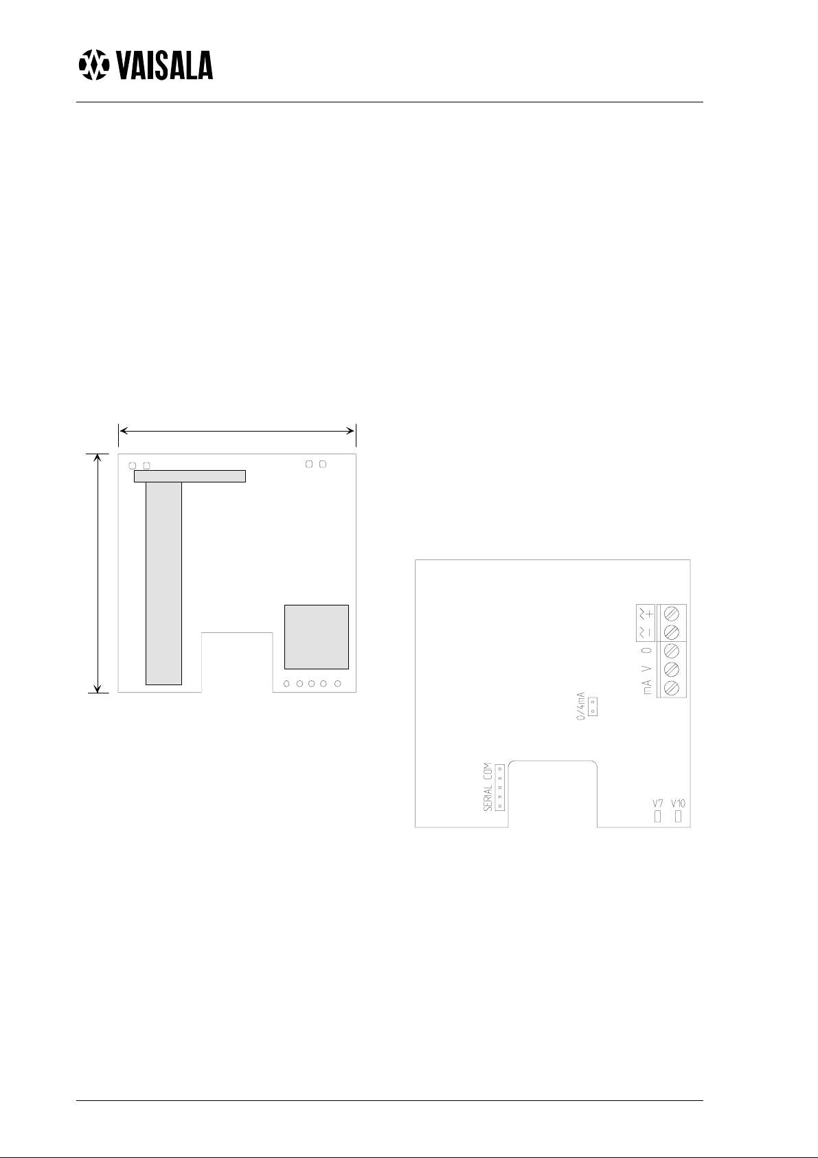
72 mm
ELECTRICAL CONNECTIONS
The nominal 24 V supply must be
connected between terminals + and - on
the mother board. The analogue output is
available at remaining terminals. The
common wire is connected to terminal 0
and the other wire either to terminal V
(voltage output) or to terminal mA
(current output). The current output is
chosen with the jumper 0/4mA (see
Figure 3): 4...20mA is chosen by
connecting the jumper (default) and the
2
0...20 mA is chosen by disconnecting the
jumper. If the relay output of display
models is used, note that the wiring is
done at the back of the display board.
The default relay trigger point has been
set to 1000 ppm. This can be changed
with the optional software kit 19222GM.
For further details, contact your local
Vaisala representative.
74 mm
Figure 1 Dimensions
Figure 2 Electrical connections and
leds V7, V10
Note that during normal operation the
green led (V10) at the lower righthand
corner is blinking. In case the selfdiagnostics procedure comes across some
abnormality, the red led (V7) lights up
(see Figure 2 above).
1999-11-16
Page 2

GMM20W CO
Sensor Systems Division U300en-1.1
module
2
SERVICE AND MAINTENANCE
The GMM20W module has an excellent
stability and requires almost no maintenance. A full after sales calibration and
service facility is naturally provided by
Vaisala and its distributors.
In case the user prefers to do the calibration himself, calibration gases and
equipment are also available. Vaisala's
portable CO2 meters together with the
Calibration Kit provide for easy and
convenient on-site calibration checks
(see the corresponding manuals for
detailed instructions).
GMM20W should be adjusted if the
reading differs too much from the
reference value during checking (note
that in any case, only slight differences
are expected). For this purpose, we
recommend Vaisala’s Software Kit
19222GM which includes a floppy disk
and a serial COM adapter.
Connect the cable to the connector
marked “Serial Com” on the main PCB
of the module and to the connector A on
the serial COM adapter (see Figure 3).
In order to achieve full accuracy, the
module has to be calibrated against
accurate and traceable calibration gases
in stable environmental conditions
(temperature, pressure). Accurate calibrations are usually performed in laboratories; in these calibrations, temperature
and pressure corrections have to be
made. For further details, consult your
local Vaisala representative.
1999-11-16
Figure 3 Connection of the serial communication cab le
Page 3

GMM20W CO
Sensor Systems Division U300en-1.1
module
2
POWER SUPPLY REQUIREMENTS
The GMM20W module is designed to
operate from a nominal 24 VAC/VDC
supply. The power supply should maintain the voltage between 18...30 VDC or
20...26 VAC for all load conditions and
all mains voltages. The power input includes a halfwave rectifier. To avoid
current peaks, it is recommended to use
a DC supply. The average transmitter
current consumption is 85 mA
maximum but peak currents of 170 mA
may occur during normal operation.
A) NO COMMON LOOP FORMED - RECOMMENDED
24 VAC
CONNECTION TO AN AC SUPPLY
The GMM20W module can also be
connected to a 24 VAC supply without
an external rectifier. However, when
more than one module is connected to
one 24 VAC transformer, a common
loop is formed and there is an increased
risk of a short-circuit. To avoid this,
always use separate floating supply for
each module (see Figure 4A). However,
if several modules have to share one
transformer, the phase (∼) must always
be connected to + connector in each
module (see Figure 4B).
GM M 20W m odule
supply
voltage
C o n tr o lle r
signal
output
24 VAC
B) COMMON LOOP FORMED - NOT RECOMMENDED!
24 VAC
supply
voltage
GM M 20W m odule
GM M 20W m odule
supply
voltage
supply
voltage
GM M 20W m odule
signal
output
C o n tr o lle r
signal
output
signal
output
Figure 4 AC connections
shared
com m on
line
1997-07-22
Page 4

GMM20W CO
Sensor Systems Division U300en-1.1
module
2
TECHNICAL DATA
Carbon dioxide
Measuring range 0...2000 ppm CO2 (nominal)
(can be recalibrated for other ranges: 0...5000 ppm, 0...10000 ppm, 0...20000 ppm)
Accuracy at 20°C <±[1% FS + 1.5% of the reading]
(including non-linearity and calibration uncertainty)
Repeatability <+1 % FS
Temperature dependence
of output < 0.05 %FS / °C
Long-term stability
(in ambient conditions) <±5 % / 5 years
Response time (0...67%) 1 minute
Operating conditions
Operating temperature -5...+45 °C
Storage temperature -20...+70 °C
Humidity range:
temporarily 0...100 %RH (non-condensing)
continuous use 0...85 %RH ( non-co nde nsing)
General
Output signals 0...20 mA or 4...20 mA and 0...10 V
Optional outputs relay
LonWorks
Recommended external
load: current output max. 500Ω
voltage output min. 1kΩ
Relay contact ra tings max. 50 V 0.5A
Power supply nominal 24 VDC/VAC (18...30 VDC)
Power consumption < 2.5 W
Warm-up time < 5 minutes
Dimensions: 72 x 74 x 19 mm
Weight: 56 g
interface
Accessories
Order code Description
GMI21 Display and relay option
GMR20 Relay output option
GML20
19222GM Calibration software kit (incl. disk and serial COM adapter)
18192GM Field calibration kit (used with Vaisala’s portable CO2 meter s )
The GMM20W module complies with the following standards and has passed the following
tests:
EN50081-1 (EN 55022 class B)
EN50082-1 (IEC 1000-4-3, IEC 801-4 (1988) )
LonWorks
interface option
1999-11-16
GUARANTEE
Vaisala issues a guarantee for the material and workmanship of this
product under normal operating conditions for one (1) year from the
Page 5

GMM20W CO
Sensor Systems Division U300en-1.1
module
2
date of delivery. Exceptional operating conditions, damage due to
careless handling and misapplication will void the guarantee.
1997-07-22
 Loading...