

Page 1

CO2 transmitter GMD20 and GMD20D M210292en-A
INTRODUCTION
Vaisala’s GMD20 uses silicon based CARBOCAP sensor technology providing
excellent stability and reliability. The GMD20 transmitters require almost no
maintenance: the recommended calibration interval is five years in HVAC and related
benign applications. Transmitters are available without a display (GMD20 version) and
with a display (GMD20D version).
MOUNTING
The GMD20 transmitters are truly duct mounted. The distance between the probe and the
duct wall is easily adjusted by using the mounting plate. The mounting plate is fastened
with four screws ST.4.2x16-C-Z/A4m DIN 7981. Note that four ∅3.2 holes on the duct
surface are needed, as well as one ∅22...25 mm hole in the middle (see figure below).
Insert the transmitter through the mounting plate and adjust the distance.
Figure 1 Dimensions of the GMD20 and the mounting plate (in mm)
ELECTRICAL CONNECTIONS
Open the transmitter cover and remove the display board if there is one installed. The
cable is inserted through a rubber plug included in the package. Pierce the rubber plug
with a screwdriver or a similar instrument in order to open the hole for the cable. Then
insert the plug in the appropriate hole in the transmitter cover. Strip a few millimetres of
the cable insulation and insert the cable carefully through the rubber plug so that you can
connect the wires to the terminal block on the righthand side of the component board.
42
22
42
min 80 max 140
Ø15
64
1
Page 2

The nominal 24 V supply must be connected between terminals + and -. The analogue
output is available at remaining terminals. The common wire is connected to terminal 0
and the other wire either to terminal V (voltage output) or to terminal mA (current
output). The current output type is chosen with the jumper 0/4mA (see Figure 2):
4...20mA is chosen by connecting the jumper (default) and the 0...20 mA is chosen by
disconnecting the jumper. If the relay output of the display board (in GMD20D ) is used,
connect the wires to the terminal block at the back of the display board before reinstalling it. The default relay trigger point has been set to 1000 ppm and it can be
changed with the optional software kit 19222GM. For further details, contact your local
Vaisala representative. If an optional LonWorks interface or a relay output option is
installed in the GMD20, please, refer to the corresponding manuals for details.
Note that during normal operation the green led (V10) at the lower righthand corner is
blinking. In case the self-diagnostics procedure comes across some abnormality, the red
led (V7) lights up (see Figure 2).
Figure 2 Electrical connections and leds V7, V10
SERVICE AND MAINTENANCE
The GMD20 transmitters have an excellent stability and require almost no maintenance.
In benign environments the recommended calibration interval is five years. If the reading
differs too much from the reference value during checking, the transmitter should be
removed and preferably sent to Vaisala or Vaisala distributor for re-calibration. In case
the user prefers to do the re-calibration himself, Vaisala's software Kit 19222GM and
accurate calibration gases are needed.
If full accuracy is required, the transmitter has to be calibrated against accurate and
traceable calibration gases in stable environmental conditions (temperature, pressure).
Accurate calibrations are usually performed in laboratories; in these calibrations,
temperature and pressure corrections have to be made. A full after sales calibration and
service facility is naturally provided by Vaisala and its distributors. For further details,
consult your local Vaisala representative.
CO2 transmitter GMD20 and GMD20D M210292en-A
2
Page 3
POWER SUPPLY REQUIREMENTS
The GMD20 transmitter is designed to operate from a nominal 24 VAC/VDC supply. The
power supply should maintain the voltage between 18...30 VDC or 20...26 VAC for all
load conditions and all mains voltages. The power input includes a halfwave rectifier. To
avoid current peaks, it is recommended to use a DC supply. The average transmitter current consumption is 85 mA maximum but peak currents of 170 mA may occur during
normal operation.
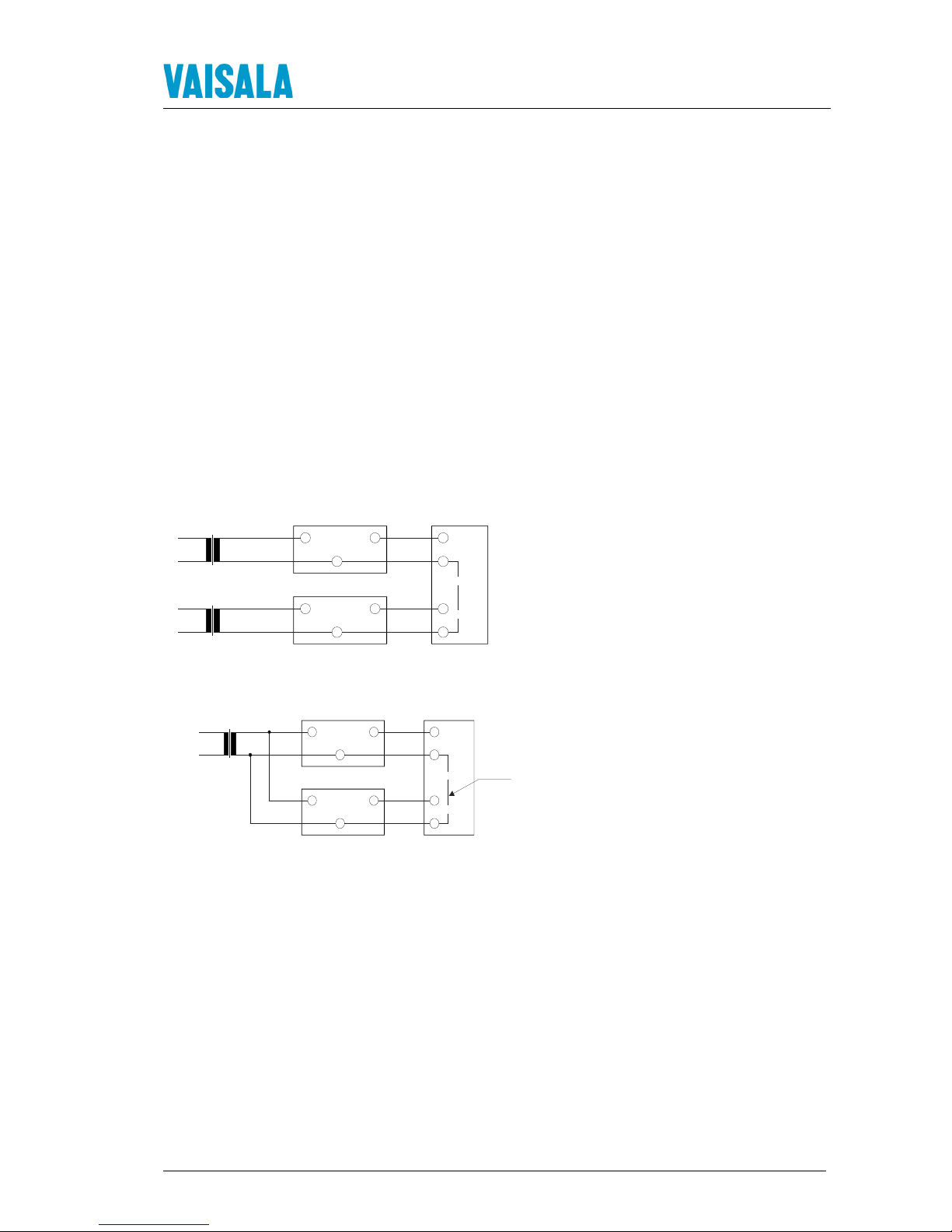
CONNECTION TO A 24 VAC SUPPLY
The GMD20 transmitters can also be connected to a 24 VAC supply without an external
rectifier. However, when more than one transmitter is connected to one 24 VAC
transformer, a common loop is formed and there is an increased risk of a short-circuit. To
avoid this, always use separate floating supply for each transmitter (see Figure 3A).
However, if several transmitters have to share one transformer, the phase (∼) must always
be connected to + connector in each transmitter (see Figure 3B).
A)
B)
Figure 3 AC connections
24V OUT
GND
24V OUT
GND
CONTROLLER
GM20
Signal
output
Signal
output
Supply
voltage
Supply
voltage
24VAC
24VAC
GM20
24V OUT
GND
24V OUT
GND
Signal
output
Signal
output
Supply
voltage
Supply
voltage
SHARED
COMMON
LINE
GM20
GM20
CONTROLLER
24VAC
CO2 transmitter GMD20 and GMD20D M210292en-A
3
Page 4
TECHNICAL DATA
Carbon dioxide
Measuring range 0...2000 ppm CO2 (nominal); with recalibration 0...5000 ppm CO2,
0...10 000 ppm CO
2
, 0...20 000 ppm CO
2
Accuracy at 20°C against
certified factory references <±[30 ppm + 2.0 % of the reading]
(including repeatability and calibration uncertainty)
Non-linearity <±1.0 %FS
Temperature dependence
of output (typical) < 0.15 %FS / °C (reference 25°C)
Long-term stability <±5 %FS / 5 years
Response time (0…63%) 1 minute
Operating conditions
Operating temperature -5...+45 °C
Storage temperature -20...+70 °C
Humidity range short term 0...85 %RH (non-condensing)
Air flow range 0...10 m/s
General
Analogue outputs 0...20 mA or 4...20 mA and 0...10 V
Resolution of analog outputs 0.5 % FS
Recommended external load:
current output max. 500 Ω
voltage output min. 1kΩ
Relay contact ratings max. 50 V 0.5 A
Power supply nominal 24 VDC/VAC (18...30 VDC)
Power consumption < 2.5 W average
Warm-up time < 15 minutes
Mechanics
Housing material ABS plastic
Housing classification IP65
(electronics housing)
Weight:
GMD20 140 g
GMD20D 170 g
ACCESSORIES
Order code Description
GMR20 Relay output option (not for the GMD20D)
GML20
LonWorksinterface option (not for the GMD20D )
GM35001 Calibration pipe
19222GM Calibration software kit (incl. disk and serial COM adapter)
GUARANTEE
Vaisala issues a guarantee for the material and workmanship of this product under
normal operating conditions for one (1) year from the date of delivery. Exceptional
operating conditions, damage due to careless handling and misapplication will void
the guarantee.
CO2 transmitter GMD20 and GMD20D M210292en-A
4
*M210292
EN
*
 Loading...