

Page 1

IM-EN-FC11-QG-A
Quick Guide
Field Communicator
FC-11
Page 2
Field Communicator FC-11 Quick Guide
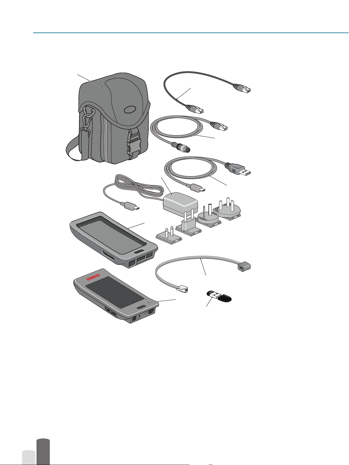
Kit contents
4
5
6
3
9
2
x
x
PR-33-AC
172.16.23.108
23.15
nD 1.37924 NORMAL OPERATION 27.36°C
R09690
MAIN MENU
REMOTE DISPLAY
DIAGNOSTICS
TOOLS
DATA LOGGING
SETTINGS
1
7
8
1. FC-11 Field Communicator
2. PR-8817 Protective rubber cover
3. PR-8815 Standard micro-USB charger
4. PR-8812 Carrying case for FC-11 Field Communicator
5. PR-8814 Ethernet cable, RJ-45 10/100, 0.5 m / 1.6 ft
6. PR-8330-001 Ethernet cable for PR-33-AC, 1 m / 3.3 ft
7. PR-8811 Power adapter cable for PR-23 Indicating transmitter DTR
8. PR-8818 USB memory stick
9. PR-8813 Standard USB to micro-USB cable, 0.5 m/1.6 ft
2
Document/Revision No. IM-EN-FC11-QG-A
Eective: March 1, 2020
Page 3
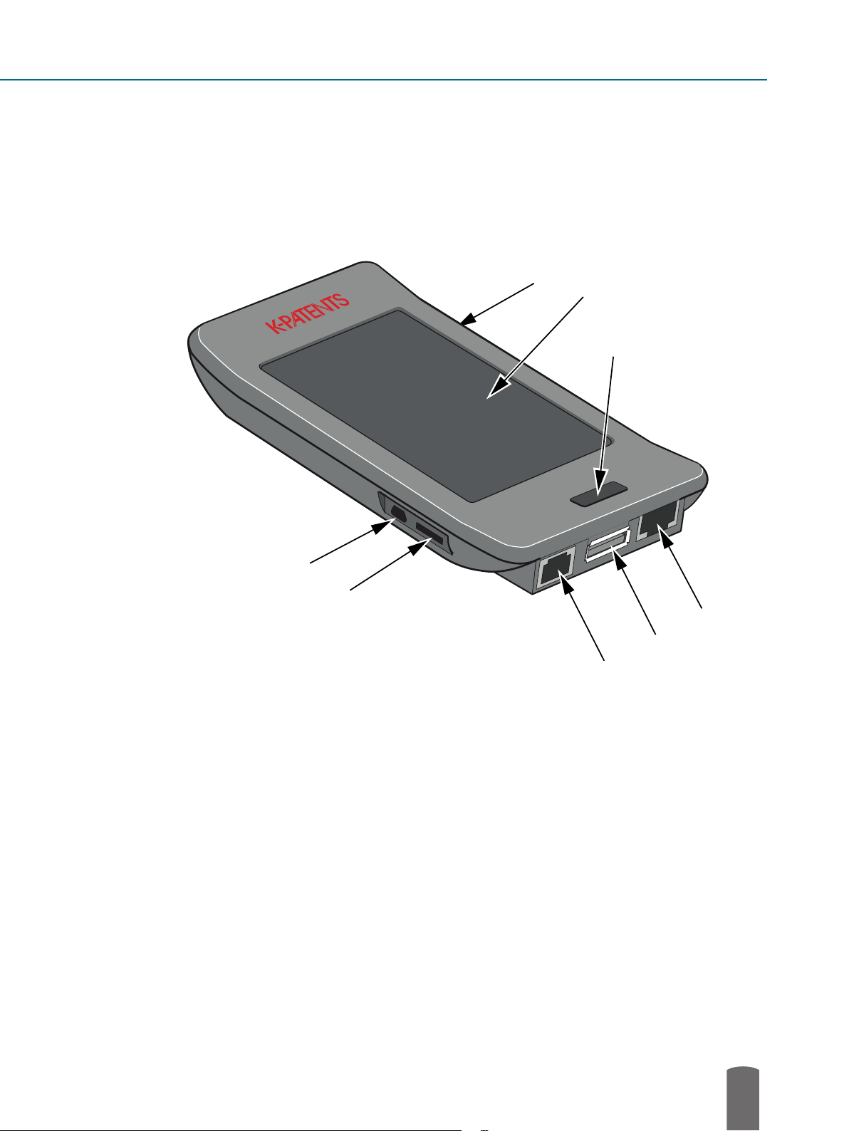
Field Communicator FC-11
172.16.23.108
23.15
MAIN MENU
nD 1.37924 NORMAL OPERATION 27.36°C
1
2
x
PR-33-AC
R09690
REMOTE DISPLAY
DIAGNOSTICS
TOOLS
DATA LOGGING
SETTINGS
8
7
6
5
4
3
1. Micro-USB connection (for charging and connecting to a computer)
2. Not in use
3. DTR power connection
4. USB connection (for memory stick)
5. Ethernet connector
6. Button
7. Touch screen
8. Not in use
© Copyright Vaisala Oyj 2020. All rights reserved.
3
Page 4

Field Communicator FC-11 Quick Guide
Connecting
The FC-11 can be connected without shutting down the refractometer system or the communicator.
Connect one end of the suitable ethernet cable to the Field Communicator FC-11 and the other
end to your instrument. The charge in FC-11 lasts 2-3 hrs, connect to an appropriate power outlet
for longer usage time.
• With a PR-43 refractometer use Split cable PR-8444. External power source is needed.
• With PR-33-AC use the PR-8330-001 cable included in the delivery. Separate power source
is not needed.
• With a PR-33-S the ethernet is connected to the PoE switch. Note that FC-11 cannot charge
from a PoE switch, so an external power source is needed.
• In a PR-23 system the FC-11 is connected to the DTR. Use the provided power cable PR-8811
to get power from DTR.
• In a DD-23 system the FC-11 is connected to the ethernet output in the Divert Unit.
For additional information see the FC-11 instruction manual, chapter 2.
P4-042
172.16.23.108
23.15
nD 1.37924 NORMAL OPERATION 27.36°C
x
PR-33-AC
R09690
MAIN MENU
REMOTE DISPLAY
DIAGNOSTICS
FC-11
TOOLS
DATA LOGGING
SETTINGS
RJ45
Connecting FC-11 to a PR-43 refractometer
Cable PR-8444
mA Power
4
Document/Revision No. IM-EN-FC11-QG-A
Eective: March 1, 2020
Page 5

Connecting FC-11 to a PR-33-AC refractometer
© Copyright Vaisala Oyj 2020. All rights reserved.
5
Page 6

Field Communicator FC-11 Quick Guide
x
PR-33-AC
R09690
95%
172.16.23.182
172.16.23.108
23.15
A
MAIN MENU
nD 1.3818 NORMAL OPERATION 27.5°C
MAIN MENU
nD 1.37924 NORMAL OPERATION 27.36°C
MEASUREMENT
MEASURMENT
DIAGNOSTICS
DIAGNOSTICS
TOOLS
?
TOOLS
DEVICE INFO
DATA LOGGING
SETTINGS
SETTINGS
Connecting FC-11 to a DTR
Start the Field Communicator by pressing the button (6) until the light on the button turns red.
The startup screen will show briey. The eld communicator will look for your instrument and if it
is found, you get the main screen. If your instrument is in a factory network or the IP address has
been otherwise changed, you’ll need to enter the IP address manually.
Startup screen IP address
Main screen
screen
6
Document/Revision No. IM-EN-FC11-QG-A
Eective: March 1, 2020
Page 7

Using FC-11
Tap the screen to choose a function. To get back, tap the little triangle on top of the screen or
press the button.
Viewing measurement
To view the real-time measurement, go to Measurement, then to View measurement.
The plotted measurement value can be changed by touching the grey area of the y-axis. The
plotted measurement value can be either CALC, CONC, T or nD. CALC is the calculated
concentration value without Field calibration adjustment, CONC is the nal concentration value
including Field calibration adjustment. T indicates temperature, while nD is the refractive index
value nD of the refractometer.
© Copyright Vaisala Oyj 2020. All rights reserved.
7
Page 8

Field Communicator FC-11 Quick Guide
The graph is automatically scaled based on measurement values. Time scale for the graph can
be set to 3, 10 or 30 minutes. The time scale can be altered by touching on the grey area of the
x-axis. The image can be dragged horizontally to see older data values.
Note: Measurement values older than 2 hrs are discarded from the real-time view.
Viewing measurement
Viewing optical image
To view the optical image, go to to Diagnostics, then to Raw image.
The raw image display shows the optical image of the refractometer on all CCD photocells. Use
the + and - buttons to zoom. Areas outside the boundaries of the zoom area box can be displayed
by dragging the image.
8
Document/Revision No. IM-EN-FC11-QG-A
Eective: March 1, 2020
Page 9

Tap the refresh button (left of + and -) to load the latest image from the refractometer. If you hold
the refresh button for over 1 second, the FC-11 goes into autoload mode, in which new raw images
are loaded as quickly as possible; the autoload speed depends on your refractometer system.
Viewing optical image
Data logging
To log data, go to Measurement, then Data logging. Choose your logging interval, then tap Start
to start the logging process. If a USB stick is connected to the USB connector (4) at the bottom
of the FC-11, data will be written onto the stick. If there’s no USB memory available, the logged
data is kept in internal memory.
For additional information see instruction manual, section 3.2.3.
© Copyright Vaisala Oyj 2020. All rights reserved.
9
Page 10

Field Communicator FC-11 Quick Guide
Downloading logged data
If you are logging onto a USB stick, stop the logging process. Then you can remove the USB stick
and plug it into your computer.
If your logging data is written into the internal memory of FC-11, stop the logging process. Then
use the micro-USB connection on FC-11 (2) and a standard micro-USB-USB cable (included in
the delivery) to connect the device to your computer.
In both cases your computer will show the plugged-in USB connection as a new disk. Click on
the disk name to open the memory. Note. The FC-11 will not show up if logging is still going on.
Your logging data is written to a folder named with the serial number of the refractometer
you logged.
In that folder you nd one or several text les identied with instrument serial number, date
and time.
The le format is plain text. The le can be opened as such or it can be imported e.g. to Excel for
further examination.
10
Document/Revision No. IM-EN-FC11-QG-A
Eective: March 1, 2020
Page 11

Troubleshooting
When inactive, the FC-11 is programmed to dim and later turn o the display to conserve energy.
Tap anywhere on the screen or press the button to show the display. The Dim time and O time
can be changed in Settings menu.
When the FC-11 is used on battery power, it shuts down when the battery is empty. After plugging
in the power, restart the device by pressing the button until the light turns red. Then re-enter date
and time with the Set Time/Date command in the Settings menu. Make sure the current date
and time are entered before resuming any logging operation. Note: If the IP address is entered
manually to FC-11, you have to reenter it to connect to your instrument.
Some commands are not available when connected to a Divert Control System DD-23. Also, if
the FC-11 is logging, some commands like the Tools menu are unavailable. If you connect the
FC-11 to a computer, but the FC-11 does not show up as an external disk as it should, that may be
because logging is on. Stop logging rst, then connect to the computer. If the use of USB is limited
or forbidden on your computer, FC-11 will charge through the micro-USB to USB cable, but will
not show as an external disk. Contact your system administration about allowing the connection
Disposal
When wishing to dispose of a FC-11, please observe local and national regulations
and requirements for the disposal of electrical and electronic equipment.
© Copyright Vaisala Oyj 2020. All rights reserved.
11
Page 12

www.vaisala.com
 Loading...