


Liebert®
DS™ ThermalManagementSystem
Installer/User Guide
35to 105kW (10to 30ton) Capacity, UpflowandDownflow, 50and60Hz, Air-cooled,
Water/Glycol-cooled, GLYCOOL™EconomizerCoil,
Dual-CoolDXwithSecondaryChilled-waterCoil

The information contained in this document is subject to change without notice
and may not be suitable for all applications. While every precaution has been
taken to ensure the accuracy and completeness of this document, Vertiv
assumes no responsibility and disclaims all liability for damages resulting from
use of this information or for any errors or omissions. Refer to other local
practices or building codes as applicable for the correct methods, tools, and
materials to be used in performing procedures not specifically described in this
document.
The products covered by this instruction manual are manufactured and/or sold
by Vertiv. This document is the property of Vertiv and contains confidential
and proprietary information owned by Vertiv. Any copying, use or disclosure of
it without the written permission of Vertiv is strictly prohibited.
Names of companies and products are trademarks or registered trademarks of
the respective companies. Any questions regarding usage of trademark names
should be directed to the original manufacturer.
Technical Support Site
If you encounter any installation or operational issues with your product, check the pertinent section of this
manual to see if the issue can be resolved by following outlined procedures.
Visit https://www.Vertiv.com/en-us/support/ for additional assistance.
Vertiv | Liebert® DS ™ In staller/User Guide

TABLE OF CONTENTS
1 Important Safety Instructions 1
2 Nomenclature and Components 9
2.1 Liebert DS Model Number Nomenclature 9
2.2 Component Location 11
3 Pre-installation PreparationandGuidelines 13
3.1 Planning Dimensions 13
3.2 Air Distribution Considerations for Downflow Units 14
3.3 Air Distribution Considerations for Upflow Units 16
3.4 Connections and System Setup 17
3.5 Operating Conditions 18
3.5.1 Cooling, Humidification and Dehumidification 18
3.5.2 Heating 18
3.6 Shipping Dimensions andUnitWeights 18
4 Equipment Inspection and Handling 21
4.1 Packaging Material 21
4.2 Handling the Unit while Packaged 22
4.3 Unpacking the Unit 23
4.3.1 Removing the Unit from the Skid with a Forklift 23
4.3.2 Removing the Unit from theSkid Using Rigging 24
4.3.3 Moving the Unit to the Installation Location Using Piano Jacks 26
4.4 Remove Shipping Blocks fromUnitswithSemi-HermeticCompressors 27
4.5 Placing the Unit on a Floor Stand 28
5 Piping and Refrigerant Requirements 29
5.1 Drain and Humidifier Fluid Piping 31
5.1.1 Field-installed, Gravity Fed Drain Line Requirements 32
5.1.2 Condensate Pump Drain Line Requirements 34
5.1.3 Water Supply Line Requirements for the Optional Humidifier 34
5.2 Refrigerant Piping and Charging 34
5.2.1 Refrigerant Piping Guidelines forAir CooledSystems 35
5.2.2 Refrigerant Line Sizes and Equivalent Lengths 36
5.2.3 Refrigerant Charge Requirements for Air Cooled Systems 37
5.2.4 Additional Oil Requirements forScrollandDigital ScrollCompressors 39
5.2.5 Evacuation, Leak Testing, and Charging Air CooledSystems withoutLiebertLee-Temp™ Receivers 42
5.2.6 Evacuation, Leak Testing, and Charging Air Cooled Systems withLiebertLee-Temp™ “Flooded
Condenser” Head PressureControlSystem 46
5.3 Refrigerant Charge for Water/Glycol Cooled Systems 48
5.4 Water/Glycol Loop Piping Guidelines 49
5.4.1 Leak Checking for Unit and Field Installed Piping 50
i

6 Electrical Connections 51
7 EC Fans and Plenums 53
7.1 Downflow Units with EC Fans 53
7.1.1 Lowering the EC Fans into the Floor Stand on Downflow Models 53
7.2 Upflow Unit Plenums with EC Fans 56
7.2.1 Assembly Inspection 57
7.2.2 Assemble Plenum Rear and Side Panels 62
7.2.3 Place Assembled Panels and EC Fans on Top of Unit 66
7.2.4 Wire the EC Fans 70
7.2.5 Install Front Panels on Plenum 72
8 Checklist for Completed Installation 83
8.1 Moving and Placing Equipment 83
8.2 Electrical Installation Checks 83
8.3 Piping Installation Checks 83
8.4 Other Installation Checks 83
9 Initial Start up Checks andCommissioning ProcedureforWarrantyInspection 85
10 Maintenance 87
10.1 Filters 88
10.1.1 Filter Replacement for Downflow Units 88
10.1.2 Filter Replacement for Upflow Units 89
10.2 Blower Drive System—EC Fans 91
10.2.1 Protective Features 92
10.2.2 Fan Impellers and Bearings Maintenance 92
10.2.3 Fan Assembly Troubleshooting 92
10.2.4 Removing EC Fans from Downflow Units 96
10.2.5 Removing EC Fans from Upflow Units 100
10.3 Blower Drive System—Forward Curved Blowers 103
10.3.1 Upflow Motor Access 104
10.3.2 Belt Removal 104
10.3.3 Belt Installation and Tensioning 105
10.3.4 Blower Bearing Maintenance 106
10.3.5 Blower Bearing Inspection 106
10.3.6 Blower Bearing Replacement 106
10.3.7 Blower Motor 106
10.3.8 Blower Motor Lubrication 106
10.3.9 Blower Wheel 106
10.4 Infrared Humidifier Maintenance 107
10.4.1 Cleaning Humidifier Pan and Float Switch 107
10.4.2 Changing Humidifier Lamps 108
10.5 Condensate Drain and Condensate Pump System Maintenance 109
ii
Vertiv | Liebert® DS ™ In staller/User Guide

10.5.1 Condensate Drain 109
10.5.2 Condensate Pump 109
10.6 Air Cooled Condenser and Drycooler Maintenance 110
10.7 Electric Reheat Maintenance 110
10.8 Thermostatic Expansion Valve (TXV) Maintenance 110
10.8.1 Determining Suction Superheat 110
10.8.2 Adjusting Superheat Setting with the TXV 110
10.9 Compressor Maintenance 111
10.9.1 Compressor Oil 111
10.9.2 Scroll and Digital Scroll Compressor Maintenance 111
10.9.3 Semi-Hermetic Compressor Maintenance 112
10.9.4 Replacement Compressors 112
10.9.5 Rotalock Valve on Scroll and Digital-Scroll Compressors 112
10.9.6 Unloading Solenoids on a Digital Scroll Compressor 113
10.9.7 Compressor Electrical Failure (Motor Burnout) 113
10.9.8 Replacing a Compressor with Electrical Failure (MotorBurnout) 114
10.9.9 Compressor Mechanical Failure 115
10.9.10 Replacing a Compressor with Mechanical Failure 115
10.10 Motorized Ball Valve (MBV) Maintenance (Digital Scroll Compressors) 115
10.10.1 MBV Control 116
10.10.2 MBV Control Method 116
10.10.3 MBV Adjustment 116
10.10.4 MBV Start-up 116
10.10.5 MBV Location 116
10.10.6 MBV Manual Control 116
10.11 Facility Fluid and Piping Maintenance forWaterandGlycolSystems 116
10.12 Glycol Solution Maintenance 117
10.13 Paradenser™—Water Cooled Condenser Maintenance 117
10.13.1 Cleaning the Paradenser 117
10.13.2 Water Regulating Valves Maintenance forSemi-HermeticandStandard ScrollCompressors 118
10.14 Drycooler Aquastat Settings 119
11 Preventive Maintenance Checklist 121
Appendices 127
Appendix A: Technical Support and Contacts 127
Appendix B: Disassembling the DS for Transport 129
Appendix C: Submittal Drawings 139
iii

This page intentionally left blank
iv
Vertiv | Liebert® DS ™ In staller/User Guide

1 IMPORTANT SAFETY INSTRUCTIONS
SAVE THESE INSTRUCTIONS
This manual contains important safety instructions that should be followed during the installation and maintenance of the
Liebert®DS. Read this manual thoroughly before attempting to install or operate this unit.
Only qualified personnel should move, install or service this equipment.
Adhere to all warnings, cautions, notices and installation, operating and safety instructions on the unit and in this manual.
Follow all installation, operation and maintenance instructions and all applicable national and local building, electrical and
plumbing codes.
WARNING! Arc flash and electric shock hazard. Open all local and remote electric power-supply disconnect
switches, verify with a voltmeter that power is Off and wear appropriate, OSHA-approved personal protective
equipment (PPE) per NFPA 70E before working within the electric control enclosure. Failure to comply can
cause serious injury or death. Customer must provide earth ground to unit, per NEC, CEC and local codes, as
applicable. Before proceeding with installation, read all instructions, verify that all the parts are included and
check the nameplate to be sure the voltage matches available utility power. The Liebert® controller does not
isolate power from the unit, even in the “Unit Off” mode. Some internal components require and receive
power even during the “Unit Off” mode of the controller. The factory-supplied, optional disconnect switch is
inside the unit. The line side of this switch contains live high-voltage. The only way to ensure that there is NO
voltage inside the unit is to install and open a remote disconnect switch. Refer to unit electrical schematic.
Follow all local codes.
WARNING! Risk of electric shock. Can cause equipment damage, injury or death. Open all local and remote
electric power supply disconnect switches and verify with a voltmeter that power is off before working within
any electric connection enclosures. Service and maintenance work must be performed only by properly
trained and qualified personnel and in accordance with applicable regulations and manufacturers’
specifications. Opening or removing the covers to any equipment may expose personnel to lethal voltages
within the unit even when it is apparently not operating and the input wiring is disconnected from the
electrical source.
WARNING! Risk of electric shock. Can cause serious injury or death. The Liebert® iCOM microprocessor does
not isolate power from the unit, even in the "Unit Off" mode. Some internal components require and receive
power even during the "unit off" mode of the Liebert® iCOM control. Open all local and remote electric power
disconnect switches and verify with a voltmeter that power is Off before working on any component of the
system.
WARNING! Risk of electric shock. Can cause serious injury or death. Open all local and remote electric power
supply disconnect switches and verify with a voltmeter that power is off before working within the fan-motor
electric-connection enclosures. Fan-motor controls can maintain an electric charge for 10 minutes after
power is disconnected. Wait 10 minutes after power is verified as off before working within the electric
control/connection enclosures. Use only fully-trained and qualified HVAC technicians to perform
maintenance on the fans.
1 Important Safety Instructions
1

WARNING! Risk of electric shock. Can cause injury or death. Open all local and remote electric power-supply
disconnect switches and verify that power is Off with a voltmeter before working within the condensate
pump electrical connection enclosure. The Liebert® iCOM™ does not isolate power from the unit, even in the
“Unit Off” mode. Some internal components require and receive power even during the “Unit Off” mode of the
Liebert®iCOM.
WARNING! Risk of electric shock. Can cause serious injury or death. The Liebert® iCOM microprocessor does
not isolate power from the unit, even in the "Unit Off" mode. Some internal components require and receive
power even during the "unit off" mode of the Liebert® iCOM control. Open all local and remote electric power
disconnect switches and verify with a voltmeter that power is Off before working on any component of the
system.
WARNING! Risk of over-pressurization of the refrigeration system. Can cause explosive discharge of highpressure refrigerant, loss of refrigerant, environmental pollution, equipment damage, injury, or death. This
unit contains fluids and gases under high pressure. Use extreme caution when charging the refrigerant
system. Do not pressurize the system higher than the design pressure marked on the unit's nameplate. For
systems requiring EU CE compliance (50Hz), the system installer must provide and install a pressure relief
valve in the high side refrigerant circuit that is rated same as the refrigerant high side “Max Allowable
Pressure” rating that is marked on the unit serial tag. Do not install a shutoff valve between the compressor
and the field installed relief valve. The pressure relief valve must be CE-certified to the EU Pressure
Equipment Directive by an EU “Notified Body.”
WARNING! Risk of very heavy 125-lb (56.7-kg) fan modules dropping downward suddenly. Can cause injury or
death.
Support fan modules before removing mounting hardware. Use caution to keep body parts out of the fan
modules pathway during repositioning. Only properly trained and qualified personnel should work on this
equipment.
WARNING! Risk of improper moving. Can cause equipment damage, injury or death. Use only lifting
equipment that is rated for the unit weight by an OSHA-certified rating organization. The center of gravity
varies depending on the unit size and selected options. The slings must be equally spaced on either side of
the center of gravity indicator. Shipping weights and unit weights are listed in the tables in Table 2.3 on
page18. Use the center of gravity indicators on the unit to determine the position of the slings.
WARNING! Risk of improper piping installation, leak checking, fluid chemistry and fluid maintenance can
cause equipment damage and personal injury. Installation and service of this equipment should be done only
by qualified personnel who have been specially-trained in the installation of air-conditioning equipment and
who are wearing appropriate, OSHA-approved PPE.
2
Vertiv | Liebert® DS ™ In staller/User Guide

WARNING! Risk of contact with high-speed rotating fan blades. Can cause serious injury or death. Open all
local and remote electric power-supply disconnect switches, verify with a voltmeter that power is off, and
verify that all fan blades have stopped rotating before working in the unit cabinet or on the fan assembly. If
control voltage is applied, the fan motor can restart without warning after a power failure. Do not operate the
unit with any or all cabinet panels removed. Do not operate upflow units without installing a plenum, duct
work or guard over the blower opening(s) on the top surface of the unit cabinet. Ductwork must be
connected to the blower(s), or a plenum must be installed on the blower deck for protection from rotating
blower wheel(s) on upflow units.
WARNING! Risk of top-heavy unit falling over. Improper handling can cause equipment damage, injury or
death. Read all of the following instructions and verify that all lifting and moving equipment is rated for the
weight of the unit before attempting to move, lift, remove packaging from or prepare the unit for installation.
Unit weights are specified in Table 2.3 on page18
WARNING! Risk of improper wiring, piping, moving, lifting and handling. Can cause equipment damage,
serious injury or death. Installation and service of this equipment should be done only by qualified personnel
who have been specially-trained in the installation of air-conditioning equipment and who are wearing
appropriate, OSHA-approved PPE.
WARNING! Risk of improper wire sizing/rating and loose electrical connections. Can cause overheated wire
and electrical connection terminals resulting in smoke, fire, equipment and building damage, injury or death.
Use correctly sized copper wire only and verify that all electrical connections are tight before turning power
On. Check all electrical connections periodically and tighten as necessary.
WARNING! Risk improper drive-belt removal. Can cause the spring-loaded motor base to slam down suddenly
causing serious injury to hands and fingers from crushing and pinching. Read the directions in this manual
and on the unit instruction labels, keep hands and fingers away from pinch points, and wear appropriate,
OSHA-approved PPE when performing maintenance on the belts, motors or pulleys. Follow all directions
when servicing the unit.
WARNING! Risk of explosive discharge of high-pressure refrigerant. Can cause serious injury. Neutral and
service ports on the rotalock valve do not have a valve core. Front-seat the service valves and relieve
pressure from the compressor before loosening a part or a component attached to the service valve. Follow
local codes to properly reclaim refrigerant.
CAUTION: Risk of excessive refrigerant line pressure. Can cause tubing and component rupture resulting in
equipment damage and personal injury. Do not close off the refrigerant-line isolation valve for repairs unless
a pressure-relief valve is field- installed in the line between the isolation valve and the check valve. The
pressure-relief valve must be rated 5% to 10% higher than the system-design pressure. An increase in
ambient temperature can cause the pressure of the isolated refrigerant to rise and exceed the system-design
pressure rating (marked on the unit nameplate).
1 Important Safety Instructions
3

CAUTION: Risk of improper moving, lifting and handling. Can cause equipment damage or injury. Only
properly trained and qualified personnel should work on this equipment. Evaporator fan modules weigh in
excess of 125-lb (56.7-kg). Use proper lifting techniques and wear appropriate, OSHA-approved PPE to avoid
injury and dropping the fan module during removal. Equipment used in handling/lifting, and/or installing the
fan assembly must meet OSHA requirements. Use handling/lifting equipment rated for the weight of the fan
assembly. Use ladders rated for the weight of the fan assembly and technicians if used during installation.
Refer to handling/lifting, and/or installation equipment operating manual for manufacturer's safety
requirements and operating procedures.
CAUTION: Risk of improper moving, lifting and handling. Can cause equipment damage or injury. Only
properly trained and qualified personnel should work on this equipment. Condenser fan modules weigh in
excess of 125-lb (56.7-kg). Use proper lifting techniques and wear appropriate, OSHA-approved PPE to avoid
injury and dropping the fan module during removal. Equipment used in handling/lifting, and/or installing the
fan assembly must meet OSHA requirements. Use handling/lifting equipment rated for the weight of the fan
assembly. Use ladders rated for the weight of the fan assembly and technicians if used during installation.
Refer to handling/lifting, and/or installation equipment operating manual for manufacturer's safety
requirements and operating procedures.
CAUTION: Risk of contact with sharp edges, splinters, and exposed fasteners. Can cause injury. Only
properly trained and qualified personnel wearing appropriate, OSHA-approved PPE should attempt to move,
lift, remove packaging from or prepare the unit for installation.
CAUTION: Risk of contact with hot surfaces. Can cause injury. The electronics housing, humidifier
components, compressor, refrigerant discharge lines, fan motor, and some electrical components are
extremely hot during unit operation. Allow sufficient time for them to cool to a touch-safe temperature before
working within the unit cabinet. Use extreme caution and wear appropriate, OSHA-approved PPE when
working on or near hot components.
CAUTION: Risk of contact with extremely hot water and part surfaces. Can cause burn injury. The infrared
humidifier bulbs, metal enclosure, humidifier water, water reservoir pan and drain tubing are very hot
during and shortly after operation. Allow sufficient time for these parts to cool to a touch-safe temperature
before handling. Use extreme caution, and wear appropriate, OSHA-approved PPE when performing
maintenance on the infrared humidifier.
CAUTION: Risk of handling heavy and lengthy parts. Can cause personal injury and equipment damage.
Cabinet panels can exceed 5 ft. (1.5 m) in length and weigh more than 35 lb. (15.9 kg). Follow relevant OSHA
lifting recommendations and consider using a two-person lift for safe and comfortable removal and
installation of cabinet panels. Only properly trained and qualified personnel wearing appropriate, OSHAapproved PPE should attempt to remove or install cabinet panels.
4
Vertiv | Liebert® DS ™ In staller/User Guide

NOTICE
CAUTION: Risk of handling heavy unit and component parts. Can cause injury and equipment damage. Use
OSHA-recommended safe lifting techniques and/or lifting equipment rated for the weight of the unit.
CAUTION: Risk of smoke generation. Can cause fire suppression and alarm system activation, resulting in
injury during building evacuation and mobilization of emergency fire and rescue services. Start-up operation
of optional electric reheat elements can create smoke or fumes that can activate the facility alarm and fire
suppression system. Prepare and take appropriate steps to manage this possibility. Activating reheat during
initial start-up may burn off particulates from electric reheat elements. Before beginning initial start-up
checks, make certain that unit was installed according to the instructions in this manual. All exterior panels
must be in place.
CAUTION: Risk of exposure to harmful noise levels. Can cause hearing injury or loss. Depending on the
installation and operating conditions, a sound pressure level greater than 70dB(A) may arise. Take
appropriate technical safety measures. Operating personnel must wear appropriate, OSHA-approved PPE
and observe all appropriate hearing-protection safety requirements.
Risk of improper power-supply connection. Can cause equipment damage and loss of warranty coverage.
Prior to connecting any equipment to a main or alternate power source (for example: back-up generator
systems) for start-up, commissioning, testing, or normal operation, ensure that these sources are correctly
adjusted to the nameplate voltage and frequency of all equipment to be connected. In general, power-source
voltages should be stabilized and regulated to within ±10% of the load nameplate nominal voltage. Also, ensure
that no three-phase sources are single-phased at any time.
NOTICE
NOTICE
Risk of oil contamination with water. Can cause equipment damage.
Liebert®DS systems require the use of POE (polyolester) oil. POE oil absorbs water at a much faster rate when
exposed to air than previously used oils. Because water is the enemy of a reliable refrigeration system, extreme
care must be used when opening systems during installation or service. If water is absorbed into the POE oil, it
will not be easily removed and will not be removed through the normal evacuation process. If the oil is too wet,
it may require an oil change. POE oils also have a property that makes them act as a solvent in a refrigeration
system. Maintaining system cleanliness is extremely important because the oil will tend to bring any foreign
matter back to the compressor.
Risk of improper refrigerant charging. Can cause equipment damage.
Refrigerant charge must be weighed into air-cooled compressorized systems before they are started. Starting
scroll and digital scroll compressors without proper refrigerant charging can cause the compressors to operate
at less than 5°F (–15°C) evaporator temperature and at less than 20psig (138kPa). Operation for extended
periods at less than 20psig (138kPa) can cause premature compressor failure.
1 Important Safety Instructions
5

NOTICE
NOTICE
Risk of clogged or leaking drain lines and leaking water-supply lines. Can cause equipment and building
damage.
This unit requires a water drain connection. Drain lines must be inspected at start-up and periodically, and
maintenance must be performed to ensure that drain water runs freely through the drain system and that lines
are clear and free of obstructions and in good condition with no visible sign of damage or leaks. This unit may
also require an external water supply to operate.
Improper installation, application and service practices can result in water leakage from the unit. Water
leakage can result in catastrophic and expensive building and equipment damage and loss of critical data
center equipment.
Do not locate unit directly above any equipment that could sustain water damage.
We recommend installing a monitored fluid-detection system to immediately discover and report coolant-fluid
system and condensate drain-line leaks.
Risk of piping-system corrosion and freezing fluids. Can cause leaks resulting in equipment and expensive
building damage. Cooling coils, heat exchangers and piping systems are at high risk of freezing and premature
corrosion. Fluids in these systems must contain an inhibitor to prevent premature corrosion.
The system coolant fluid must be analyzed by a competent fluid-treatment specialist before start up to
establish the inhibitor level and evaluated at regularly scheduled intervals throughout the life of the system to
determine the pattern of inhibitor depletion. The fluid complexity and variations of required treatment
programs make it extremely important to obtain the advice of a competent and experienced fluid-treatment
specialist and follow a regularly scheduled coolant-fluid system-maintenance program.
Fluid chemistry varies greatly as do the required additives, called inhibitors, that reduce the corrosive effect of
the fluids on the piping systems and components.
The chemistry of the coolant fluid used must be considered, because some sources may contain corrosive
elements that reduce the effectiveness of the inhibited formulation. Sediment deposits prevent the formation of
a protective oxide layer on the inside of the coolant system components and piping. The coolant fluid must be
treated and circulating through the system continuously to prevent the buildup of deposits and/or growth of
bacteria. Proper inhibitor maintenance must be performed to prevent corrosion of the system.
Consult fluid manufacturer for testing and maintenance of inhibitors.
Commercial-grade coolant fluid is generally less corrosive to the common metals of construction than water
itself. It will, however, assume the corrosivity of the coolant fluid from which it is prepared and may become
increasingly corrosive with use if not properly inhibited.
Vertiv recommends installing a monitored fluid-detection system that is wired to activate the automaticclosure of field-installed coolant-fluid supply and return shut-off valves to reduce the amount of coolant-fluid
leakage and consequential equipment and building damage. The shut-off valves must be sized to close-off
against the maximum coolant-fluid system pressure in case of a catastrophic fluid leak.
6
Vertiv | Liebert® DS ™ In staller/User Guide

NOTICE
NOTICE
NOTICE
Risk of frozen pipes and corrosion from improper coolant mixture. Can cause water leaks resulting in
equipment and building damage.
When the cooling unit or piping may be exposed to freezing temperatures, charge the system with the proper
percentage of glycol and water for the coldest design ambient temperature. Automotive antifreeze is
unacceptable and must NOT be used in any glycol fluid system. Use only HVAC glycol solution that meets the
requirements of recommended industry practices. Do not use galvanized pipe.
Risk of a catastrophic water circuit rupture. Can cause expensive building and equipment damage.
Install an overflow drain pan under the unit with a monitored leak detection system in the pan and shutoff
valves in the supply and return water lines that automatically close if water is detected by the leak detection
system. The shutoff valves should be spring return and must be rated for a close-off pressure that is the same as
or higher than the supply water pressure. If it is not possible to install an overflow drain pan, then a monitored
leak detection system should be installed in the base of the unit or under the unit to actuate the shutoff valves
immediately on a leak detection signal.
The overflow drain pan should have a drain line connected to it that flows to a floor drain or maintenance sink in
case of a shutoff valve or leak detection system malfunction.
Risk of no-flow condition. Can cause equipment damage. Do not leave the water/coolant fluid-supply circuit in a
no-flow condition. Idle fluid allows the collection of sediment that prevents the formation of a protective oxide
layer on the inside of tubes. Keep unit switched On and water/coolant fluid-supply circuit system operating
continuously.
NOTICE
NOTICE
NOTICE
Risk of improper water supply. Can reduce humidifier efficiency or obstruct humidifier plumbing.
Do not use a hot water source. It will cause deposits that will eventually block the fill-valve opening.
Risk of water backing up in the drain line. Leaking and overflowing water can cause equipment and building
damage.
Do not install an external trap in the drain line. This line already has a factory-installed trap inside the cabinet.
Installation of a second trap will prevent drain-water flow and will cause the water to overflow the drain pan.
Sagging condensate drain lines may inadvertently create an external trap.
Risk of doorway/hallway interference. Can cause unit and/or structure damage. The unit may be too large to fit
through a doorway or hallway while on the skid. Measure the unit and passageway dimensions, and refer to the
installation plans prior to moving the unit to verify clearances.
1 Important Safety Instructions
7

NOTICE
Risk of damage from forklift. Can cause unit damage. Keep tines of the forklift level and at a height suitable to
fit below the skid and/or unit to prevent exterior and/or underside damage.
NOTICE
Risk of improper storage. Can cause unit damage.
Keep the unit upright, indoors and protected from dampness, freezing temperatures and contact damage.
NOTE: The Liebert® indoor cooling unit has a factory-installed, high-pressure safety switch in the high-side
refrigerant circuit. Each refrigerant receiver contains a fusible plug for fire-safety purposes. Consult your local
building code to determine whether the refrigerant piping will require additional, field-provided pressure-relief
devices.
8
Vertiv | Liebert® DS ™ In staller/User Guide

2 NOMENCLATURE AND COMPONENTS
This section describes the model number for Liebert® DS units and components.
2.1 Liebert DS Model Number Nomenclature
Table 1.2 below describes each digit of the model number.
Table 1.1 DS Model Number Example
1 2 3 4 5 6 7 8 9 10 11 12 13 14 15
D S 0 3 5 A D A 1 E I * * * *
Table 1.2 DS Model Number Digit Definitions
Digit Description
Digits 1 and 2 = Airflow Distribution
DS = Downflowstandard
VS = Upflow standard
Digit3, 4, 5 = Nominal Cooling Capacity, kW
035 = 35 kW, 10 ton
042 = 42 kW, 12 ton
053 = 53 kW, 15 ton
070 = 70 kW, 20 ton
077 = 77 kW, 22 ton
105 = 10 5 kW, 30 ton
Digit6 = Cooling Type
A = Air-cooled
D = Dual-cool, air-cooled
H = Dual-cool, water-cooled
K = GLYCOOL™ (Liebert®Economizer Coil)
W = Water/Glycol-cooled
Digit7 = Compressor Type
D = Digital scroll, R-407C
S = Scroll, R-407C
U = Semi-hermetic with 4-step, R-407C
V = Sem i-hermetic with 4-step, R-407C
(DS105 water/glycol/GLYCOOL-only)
2 Nomenclature an d Components
9

Table 1.2 DS Model Number Digit Definitions (continued)
Digit Description
Digit8 = Voltage
A = 460V - 3ph - 60Hz
B = 575V - 3ph - 60Hz
C = 208V - 3ph - 60Hz
D = 230V - 3ph - 60Hz
2 = 380V - 3ph - 60Hz
Digit9 = Fan Type
0 = Forward-curved blowers
1 = Electronically-commutated (EC) fans
Digit10 = Reheat Type
0 = None
E = 3-stage electric
Digit11 = Humidifier
0 = No humidifier
I = Infrared Humidifier
Digit12-15 = Factory Configuration Number
Not all combinations of options are available on all units:
• Digital Scroll Compressors
• Not available on VS042A with forward-curved blower
• Not available on 077 and 105 models
• 575-V available only on 035, 053 and 070 models
• Scroll Compressors
• Available on air cooled models 035–105
• Available on water/glycol models 035–070
• Scroll compressors not available on 77- and 105-kW models for water/glycol/GLYCOOL/DualCool units
• GLYCOOL Liebert® Econ-O-Coil™ Models
• Available with digital-scroll compressors on 035 to 070 models, and with semi-hermetic compressors on
077 to 105 models
• High Pressure Water Regulating Valve
• Not available on 042, 053, 070 and 077 models with semi-hermetic and scroll compressors
10
Vertiv | Liebert® DS ™ In staller/User Guide

2.2 Component Location
The unit component locations are described in the submittal documents included in the Submittal Drawings on page139
The following table lists the relevant documents by number and title.
Table 1.3 Component-location Drawings
Docu ment Number Title
DPN003706 Component Location, Downflow Models
DPN003707 Component Location, Upflow Models
2 Nomenclature an d Components
11

This page intentionally left blank
12
Vertiv | Liebert® DS ™ In staller/User Guide

3 PRE-INSTALLATION PREPARATIONANDGUIDELINES
NOTE: Before installing unit, determine whether any building alterations are required to run piping, wiring and duct
work. Follow all unit dimensional drawings and refer to the submittal engineering dimensional drawings of individual
units for proper clearances.
Refer to DS Model Number Digit Definitions on page9, and submittal drawings to determine the type of system being
installed and anticipate building alterations, piping and duct work needed.
The unit dimensions, pipe-connection locations, and piping schematics are described in the submittal documents included
in the Submittal Drawings on page139.
• Verify that the floor is level, solid and sufficient to support the unit. See Liebert DS Downflow Unit weights and
Shipping Weights—Approximate on page18 for unit weights.
• Confirm that the room is properly insulated and has a sealed vapor barrier.
• For proper humidity control, keep outside or fresh air to an absolute minimum (less than 5% of total air
circulated in the room).
• Do not install a Liebert® DS in an alcove or at the end of a long, narrow room.
• Install the units as close as possible to the largest heat load.
• Allow at least the minimum recommended clearances for maintenance and service. See the appropriate
submittal drawings for dimensions.
• We recommend installing an under-floor water detection system. Contact your Vertiv representative for
information.
3.1 Planning Dimensions
The unit, floor stand, and plenum dimensions are described in the submittal documents included in the Submittal Drawings
on page139.
The following table lists the relevant documents by number and title.
Table 2.1 Dimension Planning Drawings
Docu ment Number Title
Downflow Units
DPN003643 CabinetDimensional Data, 35 to 105 kW (10 to 30 Tons) All Blower Types
UpflowUnits
DPN003681 Cabinet Dimensional Data Upflow 35-105kW (10-30 Tons) Models with EC Fans
DPN003646 Cabinet Dimensional Data Upflow 35 to 105 kW (10-30 Tons) with Forward Curved Blower
Floor Stands
DPN003240 Floor Stand Dimensional Data 35kW - 42kW (10-12 Tons) with EC Fans
DPN003173 Floor Stand Dimensional Dta 53kW - 77 kW (15-22 Tons) with EC Fans
DPN003174 Floor StandDimensional Data 105 kW (30 Tons) Models withEC Fans
DPN003134
Floor Stand and Floor Planning Dimensional Data Upflow 35-42 kW (10-12 Tons)Models with Forward
Curved B lowers
3 Pr e-inst allation Preparationand Guidelin es
13

Table 2.1 Dimension Planning Drawings (continued)
Docu ment Number Title
DPN003141
DPN003149
Blower Outlet, Deck and Filter Box
DPN001120 Blower Outlet a nd Deck Dimensional Data Upflow 35-42 kW (10-12 Tons) with Forward Curved Blowers
DPN001191 Blower Outlet and Deck Dimensional Data Upflow 53-77kW (15-22) Tons with Forward Curved Blowers
DPN001192 B lower Outlet a nd Deck Dimensional Data Upflow 1 05kW (30 Tons)with Forward Curved Blowers
DPN001196
DPN003974
Plenums
DPN003164 Upflow P lenum Dimensional Data 35kW-105kW (10-30 Tons)Models with Foward Curved Blowers
DPN003458 Plenum Dimensional Data Upflow35-42kW (10-12 Tons)Models with EC Fans
DPN003453 P lenum Dimensional Data Upflow 53-77kW (15-22 Tons)with EC Fans
DPN003459 Plenum Dimensional Data Upflow 105kW (30 Tons) Models with EC Fans
Floor Stand and Floor Planning Dimensional Data Upflow 53-77 kW (15-22 Tons)Models with Forward
Curved B lowers
Floor Stand and Floor Planning Dimensional Data Upflow 1 05kW (30 Tons) Models with Forward Curved
Blowers
Rear Return Filter Box Dimensional Data Upflow 35-105kW (10-30 Tons)All CompressorModels with
ForwardCurved Blowers
Rear Return Filter Box Dimensional Data Upflow 35-105kW (10-30 Tons)with EC Fans All Compressor
Models
3.2 Air Distribution Considerations for Downflow Units
• Verify that the raised floor has been properly sized for the unit’s airflow and the room is free of airflow
restrictions.
• Perforated floor tiles in the raised floor should ensure minimal pressure loss.
• The raised floor must provide 7-1/2in. (191mm) of clearance.
• A minimum of 24in. (610mm) is required to operate the fans when they are lowered with the factory-provided
jacking mechanism.
• Ensure that there is adequate clearance above the unit for service, such as replacing filters.
• Optional plenums are available for downflow unit ducting.
14
Vertiv | Liebert® DS ™ In staller/User Guide

Figure 2.1 Downflow Unit Ducting and Plenum Ducting
Item Description
1 Field-fabricated duct work.
Field service access for filter replacement.
2
Minimum height = 1 2in. (305mm)
Minimum distance from unit= 2in. (51mm)
3 Optional Liebert® plenum with service-access doorfor filter replacement.
4 Direct-to-unit ducting
5 Plenum ducting
3 Pr e-inst allation Preparationand Guidelin es
15
3.3 Air Distribution Considerations for Upflow Units
Various configurations are available:
• Front return
• Rear return
• Top-front supply (forward-curved blowers)
• Top-rear supply (forward-curved blowers)
• Top, rear, and front supply with plenum (EC fans)
For in-room applications with supply and return grilles, several feet of clearance must be maintained at the intake and
discharge of the unit.
Upflow rear-return configurations use a filter box attached to the back of the unit. Allow 25in. (635mm) on one side of the
unit for access to the rear-return filter box. Refer to the rear-return installation sheet, inside the rear-return filter box
package.
Figure 2.2 Upflow Ducting Configurations (Forward Curved Blowers)
Item Description
1 Typical ducting
2 Straightsections must be 1.5 to 2. 5 times the longest blower dimension.
3 Front of unit
NOTE: Drain traps are qualified to a return duct static of negative 1.5 i.w.g. (-1.5i.w.g).
16
Vertiv | Liebert® DS ™ In staller/User Guide

Figure 2.3 Upflow Ducting Configurations for EC Fans
Item Description
1 Typical ducting. May run to either side.
2 Straight section must be 2.5 times the depth of blower.
3 Ducting only attached to flanges onprovidedplenum.
NOTE: Follow standard practices in all duct work.
3.4 Connections and System Setup
• Three-phase electrical service is required for all models. Electrical service must conform to national and local
electrical codes. See equipment nameplate for details.
• The unit requires a drain, which must comply with all applicable codes. See Field-installed, Gravity Fed Drain
Line Requirements on page32, for details.
• Plan the routing of wiring, piping and duct work to the unit. Refer to the appropriate piping connection location
drawings, piping schematics, and electrical-connection drawings for your system in Submittal Drawings on
page139.
• Water/glycol and GLYCOOL units utilizing a drycooler may require an optional aquastat setting. See Table 9.7
on page119, and Table 9.8 on page119, through Table 9.10 on page120, for drycooler aquastat setting
guidelines. Applications with the optional stat setting require field piping to be insulated to prevent
condensation.
• If seismic requirements apply, consult your Vertiv representative for information about a seismic-rated floor
stand.
NOTE: Seal openings around piping and electrical connection to prevent air leakage. Failure to do so could reduce the
unit’s cooling performance.
3 Pr e-inst allation Preparationand Guidelin es
17

3.5 Operating Conditions
The Liebert® DS must be operated in a conditioned space within the operating envelope that ASHRAE recommends for
data centers. Operating the DS outside of this envelope can decrease equipment reliability. Refer to ASHRAE’s publication,
“Thermal Guidelines for Data Processing Environments.”
3.5.1 Cooling, Humidification and Dehumidification
Return air to the unit must be no cooler than the ASHRAE recommendation of 68°F (20°C) DB and 40% RH or minimum WB
of 54°F (12.2°C) for proper unit operation. Operating below this can decrease equipment reliability.
3.5.2 Heating
The Liebert® DS is qualified for heating-only operation at temperatures not exceeding 80°F (27°C).
3.6 Shipping Dimensions andUnitWeights
Table 2.2 Liebert DS Shipping Dimensions—Domestic and Export
Cooling Type Compressor Type
035/042 053/070/077 105
LxWxH, in. (mm ) LxWxH, in. (mm ) LxWxH, in. (mm )
Air, Dual-Cool Air
Air, Dual-Cool Air Semi-hermetic —
Water/Glycol, GLYCOOL/Dual-Cool
Water
Water/Glycol, GLYCOOL/Dual-Cool
Water
Scroll or Digitalscroll
Scroll or Digitalscroll
Semi-hermetic —
90x42x82
(2286x1067x2083)
90x42x82
(2286x1067x2083)
102x42x82
(2591x1067x2083
114x42x82
(2896x1 067x2083)
114x42x82
(2896x1 067x2083)
114x42x82
(2896x1 067x2083)
136x42x82
(3454x1 067x2083)
136x42x82
(3454x1 067x2083)
—
136x42x82
(3454x1 067x2083)
Table 2.3 Liebert DS Downflow Unit weights and Shipping Weights—Approximate
Down flow D ownflow Shippin g Weights, lb (kg)
Model Number Compressor Type Cooling Type EC Fan Unit Weight, lb (kg) Dom estic, lb (kg) Export, lb (kg)
Air-cooled 1470 (668) 1608 (730) 1778 (807)
DS035-042 Scroll or Digital-scroll
DS053 Scroll or Digital-scroll
Dual Cool Air 1620 (736) 1758 (798) 1928 (875)
Water/Glycol 1780 (809) 1918 (870) 2088 (948)
GLYCOOL/Dual Cool Water 1930 (877) 2068 (939) 2238 (1016)
Air-cooled 1920 (871) 2070 (939) 2260 (1026)
Dual Cool Air 2100 (953) 2250 (1021) 2440 (1107 )
Water/Glycol 2220 (1010) 2382 (1081) 2582 (1172)
GLYCOOL/Dual Cool Water 2400 (1091) 2562 (1163) 2762 (1253)
18
Vertiv | Liebert® DS ™ In staller/User Guide

Table 2.3 Liebert DS Downflow Unit weights and Shipping Weights—Approximate (continued)
Down flow D ownflow Shippin g Weights, lb (kg)
Model Number Compressor Type Cooling Type EC Fan Unit Weight, lb (kg) Dom estic, lb (kg) Export, lb (kg)
Air-cooled 1970 (894) 2120 (962) 2310 (1048)
DS070 Scroll or Digital-scroll
Standard Scroll*
DS077
Semi-hermetic
Standard Scroll*
DS105
Semi-hermetic
Dual Cool Air 2150 (975) 2300 (1044) 2490 (1130)
Water/Glycol 2270 (1032) 2432 (1104) 2632 (1194)
GLYCOOL/Dual Cool Water 2450 (1114) 2612 (1185) 2812 (1276)
Air-cooled 2020 (916) 2170(985) 2360 (1071)
Dual Cool Air 2200 (998) 2350 (1066) 2540 (1153)
*Digital-scroll not available.
Air-cooled 2450 (1114) 2612 (1185) 2812 (1276)
Dual Cool Air 2630 (1196) 27 92 (1267) 2992 (1358)
Water/Glycol 2750 (1250) 2912 (1321) 31 12 (1412)
GLYCOOL/Dual Cool Water 2930 (1332) 3092 (1403) 3292 (1494)
Air-cooled 2660 (1207) 3103 (1408) 3323 (1508)
Dual Cool Air 301 5 (1368) 3463 (1571) 3683 (1671)
*Digital-scroll not available.
Air-cooled 2780 (1261) 3223 (1462) 3443 (1562)
Dual Cool Air 3135 (1422) 3583 (1626) 3803 (1726)
Water/Glycol 3150 (1429) 3593 (1630) 3813 (1730)
GLYCOOL/Dual Cool Water 3505 (1590) 3953 (1794) 4173 (1893)
Table 2.4 Liebert DS Upflow Unit Weights and Shipping Weights—Approximate
Model Number Compressor Type Cooling Type EC Fan Unit Weight, lb (kg)
VS035-042 Scrollor Digital-scroll
VS053 Scroll or Digital-scroll
3 Pr e-inst allation Preparationand Guidelin es
Upflow
Forward-Cu rved
Unit Weight, lb (kg)
Upflow Shipping Weights, lb (kg)
w/Forward-curved Blowers
Dom estic, lb (kg) Export, lb (kg)
Air-cooled 1370 (621) 1520 (689) 1658 (753) 1828 (830)
Dual Cool Air 1520 (689) 1670 (758) 1808 (821) 1978 (898)
Water/Glycol 1680 (762) 1830 (830) 1968 (893) 2138 (970)
GLYCOOL/Dual Cool Water 1830 (830) 1 980 (898) 2118 (961) 2288 (1038)
Air-cooled 1900 (862) 2070 (939) 2220 (1007) 2410 (1094)
Dual Cool Air 2080 (943) 2250 (1021 ) 2400 (1089) 2590 (117 5)
Water/Glycol 2200 (998) 2370 (1075) 2532 (1149) 27 32 (1240)
GLYCOOL/Dual Cool Water 2380 (1080) 2550 (1157) 2712 (1231) 2912 (1321)
19
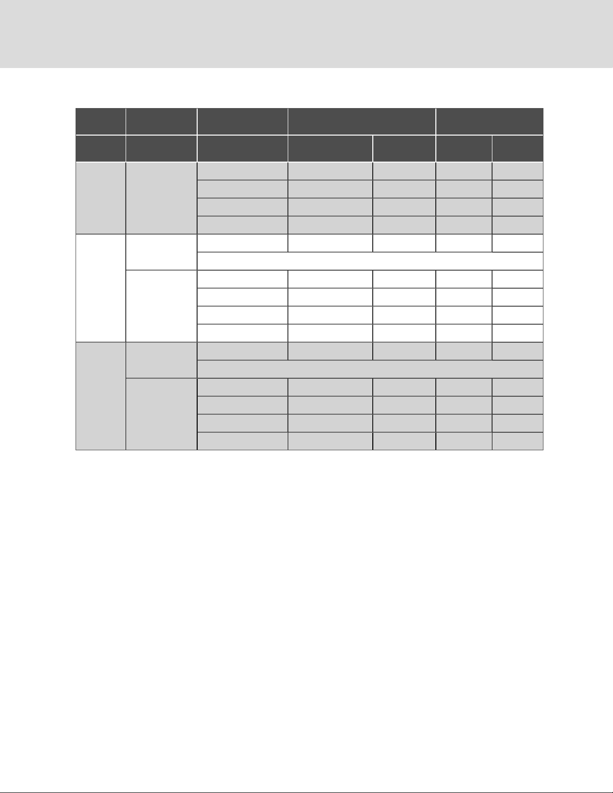
Table 2.4 Liebert DS Upflow Unit Weights and Shipping Weights—Approximate (continued)
Upflow
Upflow Shipping Weights, lb (kg)
w/Forward-curved Blowers
Model Number Compressor Type Cooling Type EC Fan Unit Weight, lb (kg)
Air-cooled 1900 (862) 2070 (939) 2220 (1007) 2410(1094)
Dual Cool Air 2080 (943) 2250 (1021 ) 2400 (1089) 2590 (117 5)
VS070 Scroll or Digital-scroll
Water/Glycol 2200 (998) 2370 (1075) 2532 (1149) 27 32 (1240)
GLYCOOL/Dual Cool Water 2380 (1080) 2550 (1157) 2712 (1231) 2912 (1321)
Air-cooled 1900 (862) 2070 (939) 2220 (1007) 2410 (1094)
Standard Scroll*
*Digital-scroll not available.
Air-cooled 2330 (1057 ) 2500 (1134) 2662 (1208) 2862 (1299)
VS077
Dual Cool Air 2510 (1139) 2680 (1216) 2842 (1290) 3042 (1380)
Semi-hermetic
Water/Glycol 2630 (1193) 2800 (1270) 2962 (1344) 3162 (1435)
GLYCOOL/Dual Cool Water 2810 (1275) 2980 (1352) 3142 (1426) 3342 (1516)
Air-cooled 2640 (11 97) 2880 (1306) 3063 (1390) 3283 (1490)
Standard Scroll*
*Digital-scroll not available.
Air-cooled 27 60 (1252) 3000 (1361) 3183 (1444) 3403 (1544)
VS105
Dual Cool Air 3090 (1402) 3330 (1510) 3513 (1594) 3733 (1694)
Semi-hermetic
Water/Glycol 3130 (1420) 337 0 (1529) 3553 (1612) 37 73 (171 2)
Forward-Cu rved
Unit Weight, lb (kg)
Dom estic, lb (kg) Export, lb (kg)
GLYCOOL/Dual Cool Water 3460 (1569) 3700 (1678) 3883 (1762) 4103 (1862)
20
Vertiv | Liebert® DS ™ In staller/User Guide

4 EQUIPMENT INSPECTION AND HANDLING
WARNING! Risk of top-heavy unit falling over. Improper handling can cause equipment damage, injury or
death. Read all of the following instructions and verify that all lifting and moving equipment is rated for the
weight of the unit before attempting to move, lift, remove packaging from or prepare the unit for installation.
WARNING! Risk of contact with sharp edges, splinters, and exposed fasteners. Can cause injury. Only
properly trained and qualified personnel wearing appropriate, OSHA-approved PPE should attempt to move,
lift, remove packaging from or prepare the unit for installation.
NOTICE
Risk of passageway interference. Can cause unit and/or structure damage. The unit may be too large to fit
through a passageway while on or off the skid. Measure the unit and passageway dimensions, and refer to the
installation plans prior to moving the unit to verify clearances.
NOTICE
Risk of damage from forklift. Can cause unit damage. Keep tines of the forklift level and at a height suitable to
fit below the skid and/or unit to prevent exterior and/or underside damage.
NOTICE
Risk of improper storage. Keep the unit upright, indoors and protected from dampness, freezing temperatures
and contact damage.
Upon arrival of the unit and before unpacking:
• Verify that the labeled equipment matches the bill of lading.
• Carefully inspect all items for visible or concealed damage.
• Report damage immediately to the carrier and file a damage claim with a copy sent to Vertiv or to your sales
representative.
Equipment Recommended for Handling the Unit:
• Forklift
• Pallet jack
• Piano jacks
• Lift beam
• Slings
• Spreader bars
4.1 Packaging Material
All material used to package this unit is recyclable. Please save for future use or dispose of the material appropriately.
4 Equipment Insp ection and Hand lin g
21

4.2 Handling the Unit while Packaged
If possible, transport the unit with a forklift or pallet jack. If that is not possible, use a crane with slings and spreader bars
that are rated for the weight of the unit.
When using a forklift or pallet jack:
• Ensure that the fork length is suitable for the unit length and, if adjustable, spread to the widest allowable
distance that will fit under the skid.
• When moving the packaged unit, lift the unit from the "HEAVY SIDE" of the unit, and do not lift the unit any
higher than 6in.(152mm). All personnel except those moving the unit must be kept 12ft (3.7m) or more from
the unit while it is being moved.
• If the unit must be lifted higher than 6in.(152mm), all personnel not directly involved in moving the unit must
be 20ft (5m) or farther from the unit.
• Always refer to the location of the center-of-gravity indicators when lifting the unit, see Figure 3.1 below.
Figure 3.1 Center of Gravity Indicator
22
Vertiv | Liebert® DS ™ In staller/User Guide

4.3 Unpacking the Unit
1. Remove the exterior stretch wrap packaging and two V-shaped boards from around the unit, as shown in Figure
3.2 below.
2. Remove the corner and side packaging planks, exposing the bag over the unit.
NOTE: The bag may remain in place to protect from dust and to protect the unit panels, or it may be removed for
immediate installation.
3. Remove the bag from the unit when ready to remove the skid and install the unit.
Figure 3.2 Unpacking the Unit
Item Description
1 Remove exterior wrap from unit
2 Remov e corner a nd side packaging planks
3 Leave the bag on the unit until ready to install.
4.3.1 Removing the Unit from the Skid with a Forklift
Refer to Figure 3.3 on the next page.
1. Align a forklift with either the front or rear side of the unit.
• Ensure that the tines of the fork lift are locked to the widest location.
• Use the center of gravity indicators on the unit panels when determining the entry points for the tines.
Center of gravity varies per unit size and selected options.
• The tines shall be equally spaced on either side of the center of gravity indicator.
2. Insert the tines of the forklift completely under the base of the unit.
• Ensure that the tines are level, not angled in an upward direction.
• The tines are to be at a height that will allow proper clearance under the unit.
• Ensure that the tines extend beyond the opposite side of the unit.
NOTE: If these steps are not followed, damage may occur to the panels and/or base of the unit.
4 Equipment Insp ection and Hand lin g
23

3. Remove the lag bolts from each bracket located around the base, and remove the brackets.
4. Lift the unit off the skid to an elevation point where the skid is not supporting the weight of the unit and remove
the skid from under the unit.
Figure 3.3 Removing From Skid with a Forklift
Item Description
1 Align forklift with front or rear of unit.
2 Insert tines c ompletely under base of unit.
3 Remove lag bolts and brackets
4 Lift unit and remove skid.
4.3.2 Removing the Unit from theSkid Using Rigging
1. Use the center-of-gravity indicators on the unit panels to determine the position of the slings.
• The slings shall be equally-spaced on either side of the center-of-gravity indicator
2. Place the slings and between the bottom rails of the unit and the skid as shown in Figure 3.4 on the facing
page.
NOTE: Unit is shown without packaging. These instructions may be followed with or without the outer packaging in
place.
24
Vertiv | Liebert® DS ™ In staller/User Guide

Figure 3.4 Example Sling Placement
Item Description
1 Distance between sling and center-of-gravity marker equal to item2.
2 Distance between sling and center-of-gravity marker equal to item1.
4 Equipment Insp ection and Hand lin g
25

3. Referring to Figure 3.5 below:
• Align the slings as described previously.
• Use spreader bars or equivalent device to ensure proper protection of the unit (Item 1).
• Remove the lag bolts from each bracket located around the base, and remove the brackets (Item 2).
NOTE: Depending on final installation location, the skid may need to remain under the unit. Therefore, the lag bolts
and brackets would not yet be removed.
• Lift the unit off the skid to an elevation point where the skid is not supporting the weight of the unit and
remove the skid from under the unit (Item 3).
Figure 3.5 Moving Unit with Rigging
Item Description
1 Spreader bars and rigging on unit.
2 Remov e lag bolts and brackets.
3 Lift the unit and remove the skid.
4.3.3 Moving the Unit to the Installation Location Using Piano Jacks
Refer to Figure 3.6 on the facing page.
1. With the unit elevated, position piano jacks at each end of the unit.
2. Lower the unit to a height suitable for the piano jacks, place protective material between the unit and the piano
jacks and straps.
26
Vertiv | Liebert® DS ™ In staller/User Guide

3. With the unit secured to the piano jacks, move the forklift away from the unit.
4. Using the piano jacks, at least two trained personnel can move the unit to the site for installation.
• For location considerations, refer to Pre-installation PreparationandGuidelines on page13.
Figure 3.6 Moving Unit with Piano Jacks
Item Description
1 Place piano jacks on each end of the unit.
2 Use padding between unit and strapsand, with the unit secured to the piano jacks, move the forklift away from the unit.
4.4 Remove Shipping Blocks fromUnitswithSemi-HermeticCompressors
The shipping blocks under all semi-hermetic compressors must be removed and the springs must be adjusted before startup.
1. Loosen nuts at each of the four compressor feet and remove the two shipping blocks.
2. Beginning with one compressor foot, re-tighten nut until the washer under the nut can no longer be rotated by
finger.
3. Loosen the nut half a turn. The washer will be slightly loose.
4. Repeat for remaining feet and recheck all when done
4 Equipment Insp ection and Hand lin g
27

4.5 Placing the Unit on a Floor Stand
Refer to the floor-stand installation sheet, located inside the floor-stand package. Lower the unit onto the floor stand. Refer to
Figure 3.7 below. Be sure to align the welded tabs on top of the floor stand with the inside of the unit frame base.
NOTE: The floor stand for the units equipped with EC fans is not symmetrical. Its orientation to the unit is critical for
lowering the EC fans. Unless the floor stand is installed in the correct position, the fans will not lower into the floor
stand.
Figure 3.7 Welded Tabs on Floor Stand
Item Description
1 Front of unit
28
Vertiv | Liebert® DS ™ In staller/User Guide

5 PIPING AND REFRIGERANT REQUIREMENTS
All fluid and refrigeration connections to the unit, with the exception of the condensate drain, are sweat copper. Factoryinstalled piping brackets must not be removed. Field-installed piping must be installed in accordance with local codes and
must be properly assembled, supported, isolated and insulated. Avoid piping runs through noise-sensitive areas, such as
office walls and conference rooms.
Refer to specific text and detailed diagrams in this manual for other unit-specific piping requirements.
All piping below the elevated floor must be located so that it offers the least resistance to air flow. Careful planning of the
piping layout under the raised floor is required to prevent the air flow from being blocked. When installing piping on the
subfloor, we recommend that the pipes be mounted in a horizontal plane rather than stacked one above the other. Whenever
possible, the pipes should be run parallel to the air flow.
The following pipe connections are required:
• A drain line from the unit.
• A water-supply line to the optional humidifier (if applicable).
• On air-cooled systems: refrigerant piping connections between the unit and the condenser. See Refrigerant
Piping and Charging on page34.
• On water-glycol systems: connections to a water or glycol loop.
The pipe connection locations, piping general arrangement and schematics are described in the submittal documents
included in the Submittal Drawings on page139.
The following tables list the relevant documents by number and title.
Table 4.1 Piping General Arrangement Drawings
Docu ment Number Title
Air Cooled Units
DPN003954 Air Cooled Piping Schematic Condenser Above Indoor Unit
DPN003730 Piping Schema tic withLiebert MC Condenser Air Cooled Scroll or Digital Scroll Compressor
Water/Glycol Cooled Units
NOTE: For systems with drycoolers, s ee Drycooler A quastat Settings on page119.
DPN000896 PipingSchematic Water/Glycol Scroll Compressor Models
DPN001430 Piping Schematic Water Glycol Digital Scroll Compressor Models
DPN000895 Piping Schematic Water/Glycol 77kW-105kW Semi-Hermetic Compressor Models
GLYCOOL™ Units
NOTE: For systems with drycoolers, s ee Drycooler A quastat Settings on page119.
DPN000897 Piping Schematic GLYCOOL™ 7 7kW -105kW Semi-Hermetic Compressor Models
DPN000898 Piping Schematic GLYCOOL™ Scroll Compressor Models
DPN001432 Piping Schematic GLYCOOL™ Digital Scroll Compressor Models
Econ-O-Coil™ Option
DPN000805 Optional Piping Schematic Econ-O-Coil Models
5 Pi pin g and Refrigeran t Requirements
29

Table 4.2 Piping Connection Drawings
Docu ment Number Title
Downflow, Air Cooled Models with EC Fans
DPN003239
DPN002182
Primary Connection Locations DownflowAir Cooled 35-42kW (10-12 Tons)Scroll or Digital Scroll
Compressor Models
Primary Connection Locations DownflowAir Cooled 53-77kW Scroll or Digital Scroll CompressorModels
with EC Fans
DPN00217 9 Primary Connections Downflow Air Cooled77kW (22 Tons) Semi-Hermetic Compressor Models
DPN002154 Primary Connection Locations Downflow Air Cooled 105kW (30 Tons) All Compressor Models
Downflow, Water/Glycol/GLYCOOL Models with EC Fans
DPN003530
DPN002183
Primary Connection Locations DownflowWater/Glycol/GLYCOOL™ 35-42kW (10-12 Tons) All Compressor
Models
Primary Connection Locations DownflowWater/Glycol/GLYCOOL™ 53-77 kW (15-22 Tons)All Compressor
Models
DPN002153 Primary Connection Locations Downflow Water/Glycol/GLYCOOL™ (30 Tons) All Compressor Models
Upflow, Air Cooled Models with EC Fans
DPN002740
DPN002742
DPN002743
Primary Connection Locations Upflow Air Cooled 35-42kW (10-12 Tons)Scroll or Digital Scroll Compressor
Models with EC Fans
Primary Connection Locations Upflow Air Cooled 77kW (22 Tons) Semi-Hermetic Compressor Models with
EC Fans
Primary Connection Locations Upflow Air Cooled 53-77kW (15-22 Tons) Scroll or Digital Scroll Compressor
Models
DPN002745 Primary Connection Locations Upflow Air Cooled 105kW (30 Tons)All Compressor Models
Upflow, Water/Glycol/GLYCOOL Models with EC Fans
DPN002741
DPN002744
Primary Connection Locations Upflow Water/Glycol/GLYCOOL ™ 35-42kW (10-12 Tons)Scroll and Digital
Scroll CompressorModels with EC Fans
Primary Connection Locations Upflow Water/Glycol/GLYCOOL™ 53-77kW (15-22 Tons)All Compressor
Models with EC Fans
DPN002746 P rimary Connection LocationsUpflow Water/Glycol/GLYCOOL ™ 105kW (30 Tons) All Compressor Models
Upflow, Air Cooled Models with Forward Curved Blowers
DPN001119
DPN00121 2
Primary Connection Locations Upflow Air Cooled 35-42kW (10-12 Tons)Scroll or Digital Scroll Compressor
Models with Forward Curved Blowers
Primary Connection Locations Upflow Air Cooled 77kW (22 Tons) Semi-Hermetic Compressor Models with
ForwardCurved Blowers
DPN00121 3 Primary Connection Locations Upflow Air Cooled 53-77 kW 15-22 Tons Scroll or Digital Scroll Compressors
DPN001257 Primary Connection Locations Upflow Air Cooled 105kW (30 Tons) All Compressor Models
30
Vertiv | Liebert® DS ™ In staller/User Guide
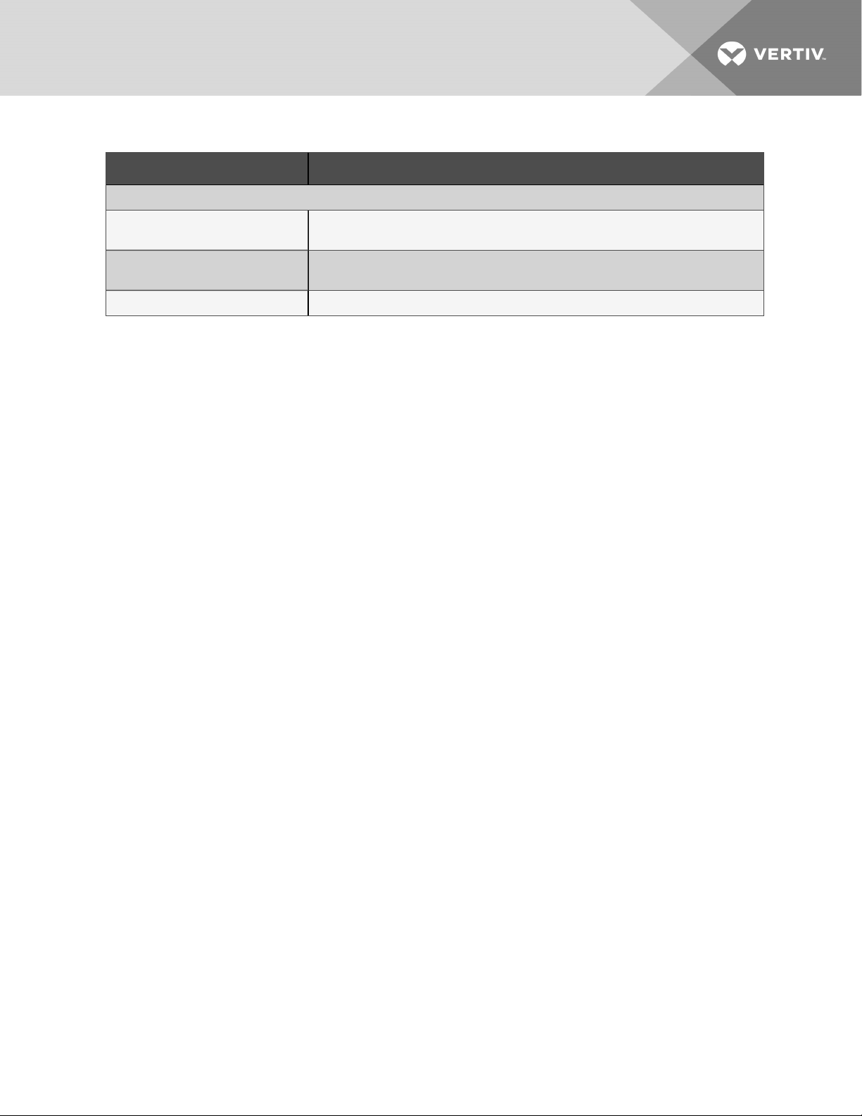
Table 4.2 Piping Connection Drawings (continued)
Docu ment Number Title
Upflow, Water/Glycol/GLYCOOL™ Models with Forward Curved Blowers
DPN001179
DPN00121 4
DPN001258 Primary Connection Locations Upflow Water/Glycol/GLYCOOL™ 1 05kW (30 Tons) All CompressorModels
Primary Connection Locations Upflow Water/Glycol/GLYCOOL™ 35-42 kW (10-12 Tons) Scroll and Digital
Scroll CompressorModels with Forward Curved B lower
Primary Connection Locations Upflow Water/Glycol/GLYCOOL™ 53-77kW (15-22 Tons)All Compressor
Models with Forward Curved Blowers
5.1 Drain and Humidifier Fluid Piping
NOTICE
Risk of water leakage. Can cause severe property damage and loss of critical data center equipment.
The Liebert®DS requires a water drain connection. Improper installation, application and service practices can
result in water leakage from the unit.
Do not locate the unit directly above any equipment that could sustain water damage.
We recommend installing monitored leak detection equipment for the water supply lines and the internal unit
water lines.
5 Pi pin g and Refrigeran t Requirements
31

5.1.1 Field-installed, Gravity Fed Drain Line Requirements
NOTICE
Risk of water backing up in the drain line. Leaking and overflowing water can cause equipment and building
damage.
Do not install an external trap in the drain line. This line already has a factory-installed trap inside the cabinet.
Installation of a second trap will prevent drain-water flow and will cause the water to overflow the drain pan.
Sagging condensate drain lines may inadvertently create an external trap.
NOTICE
Risk of a catastrophic water circuit rupture. Can cause expensive building and equipment damage.
Install an overflow drain pan under the unit with a monitored leak detection system in the pan and shutoff
valves in the supply and return water lines that automatically close if water is detected by the leak detection
system. The shutoff valves should be spring return and must be rated for a close-off pressure that is the same as
or higher than the supply water pressure. If it is not possible to install an overflow drain pan, then a monitored
leak detection system should be installed in the base of the unit or under the unit to actuate the shutoff valves
immediately on a leak detection signal.
The overflow drain pan should have a drain line connected to it that flows to a floor drain or maintenance sink in
case of a shutoff valve or leak detection system malfunction.
A 3/4-in. NPT-Female drain connection is provided on units without an optional condensate pump.
Observe the following requirements and refer to Figure 4.1 on the facing page, when installing and routing the drain line:
• The drain line must be sized for 2 gpm (7.6 l/m) flow.
• The drain line must be located so it will not be exposed to freezing temperatures.
• The drain should be the full size of the drain connection.
• The drain line must slope continuously away from the unit. Pitch drain line toward drain a minimum of 1/8in.
(3mm) per 1ft (305mm) of length.
• Drain is trapped internally. Do not externally-trap the drain line.
• The drain line must be rigid enough that it does not sag between supports, which unintentionally creates traps.
• The drain line must comply with all applicable codes.
• On units with the optional, factory-installed condensate pump, see Factory Installed Condensate Pump on
page34 and Condensate Pump Drain Line Requirements on page34.
32
Vertiv | Liebert® DS ™ In staller/User Guide

Figure 4.1 Correct and Incorrect Gravity Drains for Downflow and Upflow Units
5 Pi pin g and Refrigeran t Requirements
Table 4.3 Gravity Fed Drain Line Figure Descriptions
Item Description
1 For downflow units
2 For upflow units
3 Correct drain installation
4 Incorrect drain installation
5 Internal drain
6 External drain
7 Continuousdownward slope
33

Table 4.3 Gravity Fed Drain Line Figure Descriptions (continued)
Item Description
8 External trap. Do nottrap externally.
9 External traps, althoughunintentional. Lines m ust be rigid enough not to bowover top of other objects.
10 Internal drain
11 DS unit
5.1.2 Condensate Pump Drain Line Requirements
NOTICE
Risk of water backing up in the drain line. Leaking and overflowing water can cause equipment and building
damage.
Do not install an external trap in the drain line. This line already has a factory-installed trap inside the cabinet.
Installation of a second trap will prevent drain-water flow and will cause the water to overflow the drain pan.
Sagging condensate drain lines may inadvertently create an external trap.
Observe the following requirements when installing and routing the drain line:
• The drain line must be located so it will not be exposed to freezing temperatures.
• Size the piping based on the available condensate head.
• Drain is trapped internally. Do not externally-trap the drain line.
• The drain line must be rigid enough that it does not sag between supports, which unintentionally creates traps.
• We recommend installing monitored, under-floor leak-detection equipment.
Factory Installed Condensate Pump
If your unit includes an optional condensate pump, the pump is factory-installed inside the unit and a 1/2-in. copper sweat
connection is provided on the unit.
5.1.3 Water Supply Line Requirements for the Optional Humidifier
The unit may have an optional humidifier. Refer to the appropriate supply-line piping requirements if a humidifier is
included on your unit:
Infrared Humidifier:
• 1/4-in. supply line, maximum water pressure is 150 psi (1034kPa).
• Size supply line for 1 gpm (3.8 l/m), with a minimum water pressure of 20psi(138kPa).
• Do not supply de-ionized water to the humidifier.
5.2 Refrigerant Piping and Charging
WARNING! Risk of over-pressurization of the refrigeration system. Can cause explosive discharge of highpressure refrigerant, loss of refrigerant, environmental pollution, equipment damage, injury, or death. This
unit contains fluids and gases under high pressure. Use extreme caution when charging the refrigerant
system. Do not pressurize the system higher than the design pressure marked on the unit's nameplate.
34
Vertiv | Liebert® DS ™ In staller/User Guide

Consult local building and plumbing codes for installation requirements of additional pressure-relief devices when isolation
valves are field installed. Do not isolate any refrigerant circuits from over-pressurization protection.
NOTICE
Risk of oil contamination with water. Can cause equipment damage.
Liebert®DS systems require the use of POE (polyolester) oil. POE oil absorbs water at a much faster rate when
exposed to air than previously used oils. Because water is the enemy of a reliable refrigeration system, extreme
care must be used when opening systems during installation or service. If water is absorbed into the POE oil, it
will not be easily removed and will not be removed through the normal evacuation process. If the oil is too wet,
it may require an oil change. POE oils also have a property that makes them act as a solvent in a refrigeration
system. Maintaining system cleanliness is extremely important because the oil will tend to bring any foreign
matter back to the compressor.
5.2.1 Refrigerant Piping Guidelines forAir CooledSystems
• Air cooled units ship with a nitrogen holding charge. Do not vent the charge until all refrigerant piping is in
place, ready for connection to the unit and condenser.
• Use copper piping with a brazing alloy with a minimum temperature of 1350°F (732°C), such as Sil-Fos. Avoid
soft solders, such as 50/50 or 95/5.
• Use a flow of dry nitrogen through the piping during brazing to prevent formation of copper oxide scale inside
the piping. When copper is heated in the presence of air, copper oxide forms. POE oils will dissolve these
oxides from inside the copper pipes and deposit them throughout the system, clogging filter driers and
affecting other system components.
• A pure dry nitrogen flow of 1-3 ft3/min (0.5-1.5 l/s) inside the pipe during brazing is sufficient to displace the air.
Control the flow using a suitable measuring device.
• Ensure that the tubing surfaces to be brazed are clean and that all burrs have been removed from the ends of
the tubes.
• Ensure that all loose material has been cleaned from inside the tubing before brazing.
• Protect all refrigerant line components within 18in. (460mm) of the brazing site by wrapping them with a wet
cloth or with a suitable heat-sink compound.
• Isolate piping from building using vibration-isolating supports.
• Condenser with receiver:
• Cannot be installed below the evaporator.
• The bottom of the receiver on the outdoor, MC condenser must be higher than the elevation of the
thermal expansion valve (TXV) inside the indoor unit.
• The vertical height of the bottom of the receiver must not exceed 60 ft. (18.3m) above the TXV.
• Consult factory before installing units, condensers, and receivers outside these parameters.
• Refer to DPN003954 and DPN003993 included in the Submittal Drawings on page139.
• Condenser without receiver:
• The bottom of the condenser coil must be less than 15 feet below the location of the TXV inside the
indoor unit.
• The vertical height of the bottom of the condenser coil must not exceed 60 ft. (18.3m) above the TXV
inside of the indoor unit.
5 Pi pin g and Refrigeran t Requirements
35

• Consult factory before installing units and condensers outside of these parameters.
• Refer to DPN003954 ncluded in the Submittal Drawings on page139.
• Consult factory if piping run exceeds 150ft(46m) equivalent length.
• Install traps on hot-gas (discharge) lines at the base of vertical risers over 5ft(1.5m) and then for vertical rises
over 25 ft (7.6m), install a trap in 20-ft (6-m) increments or evenly-divided over the vertical rise.
• Pitch horizontal hot-gas piping down at a minimum rate of 1/2in.per 10ft (42mm per 10m) so that gravity will
aid in moving oil in the direction of refrigerant/oil flow.
• Keep piping clean and dry, especially on units with R-407C refrigerant.
• Avoid piping runs through noise-sensitive areas.
• Do not run piping directly in front of discharge air stream.
• Refrigerant oil. Do not mix oil types (see Compressor Oil on page111).
Refer to ASHRAE Refrigeration Handbook for general, good-practice refrigeration piping.
• Refer to Table 4.4 below,, for recommended refrigerant piping sizes based on equivalent pipe lengths.
• Refer to Refrigerant Charge Requirements for Air Cooled Systems on the facing page,, for the refrigerantcharge requirements of the system.
• Refer to Charging Air Cooled Systems withLiebertLee-Temp Receiver on page47, for charging information.
5.2.2 Refrigerant Line Sizes and Equivalent Lengths
Table 4.4 Recommended Refrigerant Line sizes for Standard Scroll Models (Non-Digital Scroll) - OD Copper (Inches)
Model: 035 04 2 053 070 077 105
Hot
Equivalent Length
50 ft (15m) 7/8 1/2 7/8 1/2 7/8 5/8 1-1/8 7/8 1-1/8 7/8 1-3/8 7/8
100 ft (30m) 7/8 5/8 7/8 5/8 1-1/8 7/8 1 -1/8 7/8 1 -1/8 7/8 1-3/8 7/8
150 ft (45m) 7/8 5/8 7/8 5/8 1-1/8 7/8 1 -1/8 7/8 1 -1/8 7/8 1-3/8 1-1/8
Consultfactory for proper line sizing for runslonger than max imum equivalent length shown.
1. Downsize vertical riser one trade size (1-1/8” to 7/8”)
Source: DPN000788, Rev 13
Gas
Line
Liquid
Line
Hot
Gas
Line
Liquid
Line
Hot
Gas
Line
Liquid
Line
Hot
Gas
Line
Liquid
Line
Hot
Gas
Line
Liquid
Line
Hot
Gas
Line
Liquid
Line
36
Vertiv | Liebert® DS ™ In staller/User Guide

Table 4.5 Recommended Refrigerant Line Sizes for 4 Step Semi-Hermetic and Digital Scroll Models - OD Copper
(Inches)
Model: 035 042 053 070 077
2
105
2
Hot
Equivalent Length
Gas
Line
Liquid
Line
50 ft (15m) 3/4 1 /2 7 /8 5/8 7/8 5/8 1-1/8
100 ft (30 m) 7/8 5/8 7 /8 5/8 1 -1/8
150 ft (45m) 7/8 5/8 1-1/8
Hot
Gas
Line
1
Liquid
Line
5/8 1 -1/8
Hot
Gas
Line
1
1
Liquid
Line
7/8 1-1/8
7/8 1-1/8
Hot
Gas
Line
Liquid
Line
1
7/8 1-1/8 7/8 1-3/8 7 /8
1
7/8 1-1/8 7/8 1-3/8 7 /8
1
7/8 1-1/8 7/8 1-3/8 1-1/8
Hot
Gas
Line
Liquid
Line
Hot
Gas
Line
Consultfactory for proper line sizing for runslonger than max imum equivalent length shown.
1. Downsize vertical riser one trade size (1-1/8” to 7/8”)
2. Digital-scroll not available on 077 or 105 models.
Source: DPN000788, Rev 13
5.2.3 Refrigerant Charge Requirements for Air Cooled Systems
The following tables provide the refrigerant charge requirements for the Liebert® DS, connected piping, and condenser
options.
Table 4.6 Approximate R-407C Refrigerant Charge forAir Cooled Liebert DS
System Type Mo del
035, 042 5.5 (2.5)
Air-cooled
053, 07 0, 077 8.0 (3.6)
Charge per C ircuit,
lb (kg)
Liquid
Line
105 9.5 (4.3)
Table 4.7 Interconnecting Piping Refrigerant Charge for R-407C, lbper 100ft (kgper30m)
Line Size, O.D ., in. Liquid Lin e Hot G as L ine
1/2 6.7 (3.0) 0.5 (0.2)
5/8 10. 8 (4.8) 0.8 (0.4)
3/4 1 6.1 (7.2) 1. 2 (0.5)
7/8 22.3 (10.0) 1.7 (0.8)
1-1/8 38.0 (17. 0) 2.9 (1. 3)
1-3/8 57.9 (25.9) 4.4 (2.0)
Source: DPN003099, Rev. 1
5 Pi pin g and Refrigeran t Requirements
37

Table 4.8 Approximate R-407C Refrigerant Required per Circuit for Liebert MC Condenser
Condenser Model
MCS056 2.2 (1.0) 21. 0 (9.5)
MCM080 3.0 (1.4) 23.9 (10.8)
MCM160 7.5 (3.4) 44.5 (20.2)
MCL110 5.1 (2.3) 2 6.0 (11. 8)
MCL220 12.2 (5.6) 53.8 (24.4)
Source: DPN002411, Rev. 8
Per Circuit witho utLiebertLee-Temp,
lb (kg)
Per Circuit withL iebertLee-Temp,
lb (kg)
38
Vertiv | Liebert® DS ™ In staller/User Guide

5.2.4 Additional Oil Requirements forScrollandDigital ScrollCompressors
NOTICE
Risk of improper compressor lubrication. Can cause compressor and refrigerant system damage.
Failure to use oil types, viscosities and quantities recommended by the compressor manufacturer may reduce
compressor life and void the compressor warranty.
• Do not mix polyolester (POE) and mineral-based oils.
• Do not mix oils of different viscosities.
• Consult your Vertiv sales representative, visit https://www.Vertiv.com/en-us/support/, or contact the
compressor manufacturer if questions arise.
System charges may require additional oil charge to be added. See Additional Oil Requirements forScrollandDigital
ScrollCompressors above, for the amount required for various system charge levels.
In addition to oil added based on system charge, additional oil is required for discharge-line field-installed traps. Standardformed tube traps are required, see Standard Formed Tube Trap Versus Straight Tubes and Fittings Trap on page41 and
Volume of Oil in Standard Form Trap by Pipe Diameter on page41, because straight tubes and fittings used as traps
require much more oil and the length of the straight tube can vary.
After the system has been fully charged with refrigerant, use a hand pump to add the additional oil at the suction side of the
system while the system is running.
5 Pi pin g and Refrigeran t Requirements
39

On the tag marked “Oil Added Field Service Record,” attached to each compressor, record the date the oil was added and
the amount of oil added by field service, including oil added for traps and for system charge per Additional Oil
Requirements forScrollandDigital ScrollCompressors on the previous page.
Table 4.9 Additional Oil Required per Circuit by System Refrigerant Charge per Circuit
Refrigerant
System C harge
Per Circuit,
lb (kg) *
DS035 DS042
<40 (18. 1) 0 0 0 0 0 0 0
40 (18.1) 0 0 8 (240) 5 (150) 5 (150) 5 (150) 5 (150)
50 (22.7) 2 (60) 2 (60) 12 (350) 9 (270) 9(270) 9 (270) 9(270)
60 (27.2) 4 (120) 4 (120) 16 (470) 13 (380) 13 (380) 1 3 (380) 1 3 (380)
70 (31.8) 5. 5 (160) 5.5 (160) 20 (590) 1 7 (500) 1 7 (500) 1 7 (500) 17 (500)
80 (36.3) 7 (210) 7 (210) 24 (710) 21 (620) 21 (620) 21 (620) 21 (620)
90 (40.8) 8,5 (250) 8,5 (250) 28 (830) 25 (740) 25 (740) 25 (740) 25 (740)
100 (45.4) 10 (300) 1 0 (300) 32 (950) 29 (860) 29 (860) 29 (860) 29 (860)
110 (49,9) 11.5 (340) 11 .5 (340) 36 (1060) 33 (980) 33 (980) 33 (980) 33 (980)
120 (54.4) 13 (380) 13 (380) 40 (1180) 37 (1090) 37 (1090) 37 (1090) 37 (1090)
DS053
60-Hz
Additional Oil Required Per Circuit, oz (ml)
DS053
50-Hz
DS070 DS077 DS105
130 (59.0) 14.5 (430) 14.5 (430) 44 (1300) 14.5 (430) 1 4.5 (430) 14.5 (430) 14.5 (430)
140 (63.5) 16 (470) 16 (470) 48 (1420) 45 (1330) 45 (1330) 45 (1330) 45 (1330)
150 (68.0) 18 (530) 18 (530) 52 (1540) 49 (1450) 49 (1450) 49 (1450) 49 (1450)
160 (72.6) 20 (590) 20 (590) 56 (1660) 53 (1570) 53 (1570) 53 (1570) 53 (1570)
170 (77.1 ) 21.5 (640) 21. 5 (640) 60 (1770) 57 (1690) 57 (1690) 57 (1690) 57 (1690)
180 (81.6) 23 (680) 23 (680) 64 (1890) 61 (1800) 61 (1800) 61 (1800) 61 (1800)
190 (86.2) 24.5 (720) 24.5 (720) 68 (2010) 65 (1920) 65 (1920) 65 (1920) 65 (1920)
200 (90.7) 26 (770) 26 (770) 72 (2130) 69 (2040) 69 (2040) 69 (2040) 69 (2040)
*System Charge = indoor unit + condenser + refrigerant receiver +refrigerant lines.
For system charges over 200 lb. (91.7kg), consult your Vertiv representative.
Use Copeland POE Oil ULTRA 32-3MAF or other Copeland-approved oils,
Source:DPN003950 Rev. 5
40
Vertiv | Liebert® DS ™ In staller/User Guide

Figure 4.2 Standard Formed Tube Trap Versus Straight Tubes and Fittings Trap
Item Description
1 Standard-formed tube trap
2 Straighttubes and fittings trap
Table 4.10 Volume of Oil in Standard Form Trap by Pipe Diameter
Pipe d iameter, in. Oil volume, oz
Source: DPN003950, Rev. 5
1/2 0.2 (5.9)
5/8 0.4 (11.8)
3/4 0.6 (17.7 )
7/8 0.9 (26.6)
1-1/8 1.8 (53.2 )
1-3/8 3.3 (97.6)
1-5/8 5.5 (162.7 )
5 Pi pin g and Refrigeran t Requirements
41

5.2.5 Evacuation, Leak Testing, and Charging Air CooledSystems withoutLiebertLee-Temp™ Receivers
Two discharge lines and two liquid lines must be field-installed between the indoor unit and the outdoor condenser. See the
appropriate piping schematic, listed in Piping General Arrangement Drawings on page29.
Evacuation and Leak Testing Air Cooled SystemswithoutLiebertLee-Temp™
For proper leak-check and evacuation, you must open all system valves and account for all check valves.
NOTE: The system includes a factory-installed check valve and an additional downstream Schrader valve with core in
the compressor discharge line. Proper evacuation of the condenser side of the compressor can be accomplished only
using the downstream Schrader valve. See the appropriate piping schematic for your system in the submittaldrawings appendix.
1. If unit power is available, open the unit liquid-line solenoid valves using the evacuation function for System #1
and System #2 in the diagnostic section of the Liebert® iCOM™ controller.
– or –
If unit power is not available, connect a field supplied 24-VAC/75-VA power source directly to the unit solenoid
valve.
2. Connect refrigerant gauges to the suction rotalock valves and discharge-line Schrader valves on both
compressors.
3. Starting with Circuit #1, open the service valves and place a 150 PSIG (1034kPa) of dry nitrogen with a tracer
of refrigerant. Check system for leaks with a suitable leak detector.
4. With pressure still in Circuit #1, open the compressor service valves in Circuit#2.
• If pressure increases in Circuit#2, the system is cross-circuited and must be re-checked for proper
piping.
• If there is no pressure increase, repeat step3 on Circuit#2.
5. After completion of leak testing, release the test pressure, (observe local code) and pull an initial deep vacuum
of 500 microns on the system with a suitable pump.
6. After 4hours, check the pressure readings and, if they have not changed, break vacuum with dry nitrogen. Pull
a second and third vacuum to 500 microns or less. Re-check the pressure after 2hours.
7. When the 3 checks are complete, proceed to ChargingAir Cooled Systems without LiebertLee-Temp below.
ChargingAir Cooled Systems without LiebertLee-Temp
NOTICE
Risk of improper refrigerant charging. Can cause equipment damage.
R-407C is a blended refrigerant and must be introduced and charged from the cylinder only as a liquid.
When adding liquid refrigerant to an operating system, it may be necessary to add the refrigerant through the
compressor suction service valve. Care must be exercised to avoid damage to the compressor. We recommend
connecting a sight glass between the charging hose and the compressor suction service valve. This will permit
adjustment of the cylinder hand valve so that liquid can leave the cylinder while allowing vapor to enter the
compressor.
42
Vertiv | Liebert® DS ™ In staller/User Guide

NOTICE
Risk of refrigerant overcharge. Can cause equipment damage.
Do not use the sight glass as an indicator when charging Liebert®condenser systems.
NOTE: A digital scroll compressor can have a clear unit sight glass on the liquid line only when operating at 100%
capacity. When operating below 100%, the unit sight glass may show bubbles with each 15 second unloading cycle.
The system must be fully piped and evacuated before it can be charged. See Evacuation and Leak Testing Air Cooled
SystemswithoutLiebertLee-Temp™ on the previous page.
Liebert® MC condensers are charge-sensitive and require accurate calculation of the system charge to avoid overcharging.
To avoid overcharge, the following additional guidelines are recommended to ensure trouble-free operation.
• When charging system in an outdoor ambient below 50°F (10°C), recheck the subcooling against Table 4.11 on
the next page, when the ambient is above 60°F (15.6°C)
• The indoor space should be maintained at 70 to 80°F (21 to 26.7°C) return air before final charge adjustments
are made.
• Charging unit at greater than 80°F (26.7°C) return air and low outdoor ambient temperature may result in the
unit being overcharged.
• Charge by subcooling measurement at the indoor unit. See Table 4.11 on the next page, for target subcooling
temperatures.
• Pressure and temperature measuring instruments should be capable of measuring to ±10psig (68.9kPa) and ±
2°F (1.1°C) for best subcooling measurement.
To charge the system:
1. Check the nameplate on the indoor unit for refrigerant type to be used. Unit control configurations differ
depending on refrigerant type.
2. The unit must be operating. Refer to the following if necessary:
• Checklist for Completed Installation on page83 to operate the system.
• The operating manual for the Liebert® MC Condenser.
Manuals are available at https://www.Vertiv.com/en-us/support/.
3. Calculate the amount of charge for the system. See Refrigerant Charge Requirements for Air Cooled Systems
on page37.
4. Accurately weigh in as much of the system charge as possible before starting the unit. Do not exceed the
calculated charge by more than 0.5 lb (0.23kg).
5. Close the Liebert® MC disconnect switch.
6. Close the Liebert® DS disconnect switch.
5 Pi pin g and Refrigeran t Requirements
43

7. In the Service menu of the Liebert® iCOM controller, select Diagnostics/Service > Diagnostics:
a. Enable Manual Mode.
NOTE: Manual Mode will time out after 30 minutes.
b. In Evaporator Fan options set Motors to On to operate the fan during Manual Mode.
c. In Compressor Circuit 1 options, set Compressor Mode to Charge to operate the compressor at full
capacity, energize the liquid-line solenoid valve, and disable reheat and humidifier.
d. Reset the charge function as many times as needed to complete unit charging.
NOTE: You must establish and maintain a minimum 20psig (138kPa) for the compressor to operate.
8. Attach pressure and temperature instruments to the liquid-line of the indoor unit, measure the initial
subcooling, and continue to add charge until the recommended subcooling for the current outdoor ambient
temperature is reached. See Table 4.11 below. Read the outdoor ambient temperature from the Liebert® MC
condenser control menu ID F02.
NOTE: To determine subcooling measurement, you must measure the liquid-line pressure reading (at the factoryinstalled Schrader tap) and obtain a temperature reading on the liquid line. Convert the liquid-line pressure reading
into a liquid temperature using a Pressure-Temperature Guide or Table 4.12 on the facing page. Subtract the
measured temperature from the saturated-liquid temperature. The difference is subcooling. Make sure to use the
saturated liquid temperature to calculate subcooling.
9. As head pressure builds, the variable-fan-speed controlled condenser fan begins rotating. The fan will run at full
speed when sufficient head pressure is developed.
Table 4.11 Target Subcooling forAmbientOutdoor
Temperature
Ambient Temp, °F(°C) Subcoo ling, °F(°C)
0 (-17.8) 22 (12.0 )
10 (-12.2) 22 (12.0 )
20 (-6.7) 22 (12.0)
30 (-1. 1) 22 (12.0)
40 (4.4) 22 (12.0)
50 (10.0) 21 (11.7)
60 (15. 6) 19 (10. 8)
70 (21.1) 17 (9.3)
80 (26.7) 13 (7.2)
90 (32. 2) 9 (5.0)
95 (35.0) 7 (3.9)
100 (37. 8) 5 (2.9)
105 (40.6) 3 (1.8)
110 (43.3) 1 (0.7 )
125 (51.7) 0
DPN002411, Rev. 8
44
Vertiv | Liebert® DS ™ In staller/User Guide

Table 4.12 Liquid Pressure andTemperature Chart—R-407C
Pressure Temperature* Temperature*
PSIG BarG °F °C
170 1 1. 7 81.5 27.5
180 1 2.4 85.1 29.5
190 13.1 88.6 31.5
200 13.8 92.0 33.3
210 14.5 95.2 35.1
220 15.2 98.3 36.8
230 15. 9 101.4 38.5
240 16.6 104.3 40. 2
250 17.2 107.2 41.8
260 17. 9 1 09.9 43.3
270 18.6 11 2. 6 44.8
280 19.3 115.3 46.3
290 20.0 117.8 47. 7
300 20. 7 120. 3 49.1
310 21. 4 122. 8 50.4
320 22. 1 125.2 51.8
330 22.8 127.5 53.1
340 23.4 129.8 54.3
350 24.1 132.1 55.6
360 24.8 1 34.3 56.8
370 25.5 136.4 58.0
380 26.2 1 38.6 59.2
390 26.9 140. 6 60.3
400 27.6 142.7 61.5
500 34.5 161. 3 71. 8
600 41.4 177.4 80.8
* Values are for saturated liquid
Source: DPN002411, Rev. 8
5 Pi pin g and Refrigeran t Requirements
45

5.2.6 Evacuation, Leak Testing, and Charging Air Cooled Systems withLiebertLee-Temp™ “Flooded
Condenser” Head PressureControlSystem
The Liebert® Lee-Temp system consists of a modulating-type head-pressure control valve and insulated receiver with
heater pad to ensure operation at ambient temperatures as low as -30°F (-34.4°C).
Two discharge lines and two liquid lines must be field-installed between the indoor unit and the outdoor condenser. See the
appropriate piping schematic, listed in Piping General Arrangement Drawings on page29.
Liebert® Lee-Temp Controlled Materials Supplied
• Built-in, pre-wired condenser control box
• Air-cooled condenser
• Piping access cover
• Bolts—4per leg (3/8in. x 5/8in.)
• Terminal block for 2 wire, 24V interlock connection between unit and condenser
• Terminal blocks for shielded, CANbus-cable connection between unit and condenser
• Condenser legs—6with 2 fan units, 8 with 2 , 3, and 4 fan units
• Bolts—6per receiver (3/8in. x 1in.)
• Liebert® Lee-Temp system:
• Insulated storage receiver with (2) liquid-level sight glasses—1 per circuit
• Head-pressure control-valve piping assembly with (2) integral check valves—1 per circuit
• Service valve—1 per receiver
• Pressure-relief valve—1 per receiver
NOTE: The Lee-Temp heater pad requires a separate, continuous electrical source. See nameplate on receiver for
proper voltage.
Evacuation and Leak Testing Air Cooled Systems withLiebertLee-Temp Receiver
For proper leak check and evacuation, you must open all system valves and account for all check valves.
NOTE: The system includes a factory-installed check valve and an additional downstream Schrader valve with core in
the compressor discharge line. Proper evacuation of the condenser side of the compressor can be accomplished only
using the downstream Schrader valve. See the appropriate piping schematic for your system in Submittal Drawings
on page139.
1. If unit power is available, open the unit liquid-line solenoid valve using the evacuation function in the diagnostic
section of the Liebert® iCOM® control.
– or –
If unit power is not available, connect a field-supplied 24-VAC/75-VA power source directly to the unit solenoid
valve.
2. Connect a jumper hose from the service-valve fitting on the outlet of the receiver and the Schrader fitting on
the discharge header of the condenser. Seat the service valve approximately twoturns from the fully backseated position.
3. On both compressors, connect refrigerant gauges to the suction rotalock valves and discharge-line Schrader
valves.
46
Vertiv | Liebert® DS ™ In staller/User Guide

4. Starting with Circuit #1, open the service valves and place a 150 PSIG (1034kPa) of dry nitrogen with a tracer
of refrigerant. Check system for leaks with a suitable leak detector.
5. With pressure still in Circuit #1, open the compressor service valves in Circuit#2.
• If pressure increases in Circuit#2, the system is cross-circuited and must be re-checked for proper
piping.
• If there is no pressure increase, repeat step4 on Circuit#2.
6. After completion of leak testing, release the test pressure, (observe local code) and pull an initial deep vacuum
of 500microns on the system with a suitable pump.
7. After 4hours, check the pressure readings and, if they have not changed, break vacuum with dry nitrogen. Pull
a second and third vacuum to 500 microns or less. Re-check the pressure after 2hours.
When the 3 checks are complete, remove the jumper hose from the service-valve fitting and the condenser, and
proceed to Charging Air Cooled Systems withLiebertLee-Temp Receiver below.
Charging Air Cooled Systems withLiebertLee-Temp Receiver
NOTICE
Risk of improper refrigerant charging. Can cause equipment damage.
R-407C is a blended refrigerant and must be introduced and charged from the cylinder only as a liquid.
When adding liquid refrigerant to an operating system, it may be necessary to add the refrigerant through the
compressor suction service valve. Care must be exercised to avoid damage to the compressor. We recommend
connecting a sight glass between the charging hose and the compressor suction service valve. This will permit
adjustment of the cylinder hand valve so that liquid can leave the cylinder while allowing vapor to enter the
compressor.
To charge the system:
1. Check the nameplate on the indoor unit for refrigerant type to be used. Unit control configurations differ
depending on refrigerant type.
2. The unit must be operating during charging, refer to Checklist for Completed Installation on page83.
3. Calculate the amount of charge for the system. See Refrigerant Charge Requirements for Air Cooled Systems
on page37.
4. Accurately weigh in as much of the system charge as possible before starting the unit.
5. Close the Liebert® MC disconnect switch.
6. Close the Liebert® DS disconnect switch.
7. In the Service menu of the Liebert® iCOM controller, select Diagnostics/Service > Diagnostics:
a. Enable Manual Mode.
NOTE: Manual Mode will time out after 30 minutes.
b. In Evaporator Fan options set Motors to On to operate the fan during Manual Mode.
c. In Compressor Circuit 1 options, set Compressor Mode to Charge to operate the compressor at full
capacity, energize the liquid-line solenoid valve, and disable reheat and humidifier.
d. Reset the charge function as many times as needed to complete unit charging.
NOTE: You must establish and maintain a minimum 20psig (138kPa) for the compressor to operate.
e. Repeat step 7 for Compressor Circuit 2.
5 Pi pin g and Refrigeran t Requirements
47

8. Check the refrigerant level in the refrigerant-level sight glass on each Lee-Temp receiver after the unit has
been operating for at least 15minutes.
NOTE: Each receiver at the condenser has 2 sight glasses and the refrigerant level varies with outside temperature.
9. Adjust the refrigerant level in each circuit to meet the level shown in Target Refrigerant Level in Sight Glasses
at Outdoor Temperatures below.
10. After adjusting the refrigerant, allow the system to operate an additional 15minutes before checking for the
need of further adjustment.
NOTE: A digital-scroll compressor can have a clear unit sight glass on the liquid line only when operating at 100%
capacity. When operating with a receiver, the unit sight glass might not become clear even when operating at 100%
capacity. When operating below 100%, the unit sight glass may show bubbles with each 15-second unloading cycle.
Target Refrigerant Level in Sight Glasses at Outdoor Temperatures
• 40°F (4.5°C) and lower—bottom sight glass is 3/4 full
• 40 to 60°F (4.5 to 15.5°C)—bottom sight glass is full
• 60°F (15.5°C) and higher—top sight glass is 3/4 full
5.3 Refrigerant Charge for Water/Glycol Cooled Systems
The water/glycol cooled system is factory-charged and includes and includes a Paradenser™ condenser and control valves.
Table 4.13 Approximate R-407C Refrigerant Factory Charge forWater/Glycol Cooled Liebert DS
System Type Model
Charge per C ircuit,
lb (kg)
035, 042 12.2 (5.6)
Water, Glycol/GLYCOOL
053, 07 0, 077 1 7. 0 (7.8)
105 22.5 (10.3)
Table 4.14 Water/Glycol Cooled and GLYCOOL Suction Pressure Transducer Settings
Fun ction
Gauge (Sea Level) psiG (kPa) Abso lute psiA (kPa)
Minimum to Start-Cooling 50 (345) 65 (448)
Freeze P rotection (DX w/Econ-O-Coil) 52 (358) 67 (461)
R-407C
48
Vertiv | Liebert® DS ™ In staller/User Guide

5.4 Water/Glycol Loop Piping Guidelines
WARNING! Risk of improper piping installation, leak checking, fluid chemistry and fluid maintenance can
cause equipment damage and personal injury. Installation and service of this equipment should be done only
by qualified personnel who have been specially-trained in the installation of air-conditioning equipment and
who are wearing appropriate, OSHA-approved PPE.
NOTICE
Risk of frozen pipes and corrosion from improper coolant mixture. Can cause water leaks resulting in
equipment and building damage.
When the cooling unit or piping may be exposed to freezing temperatures, charge the system with the proper
percentage of glycol and water for the coldest design ambient temperature. Automotive antifreeze is
unacceptable and must NOT be used in any glycol fluid system. Use only HVAC glycol solution that meets the
requirements of recommended industry practices. Do not use galvanized pipe.
NOTICE
Risk of piping-system corrosion and freezing fluids. Can cause leaks resulting in equipment and expensive
building damage. Cooling coils, heat exchangers and piping systems are at high risk of freezing and premature
corrosion. Fluids in these systems must contain an inhibitor to prevent premature corrosion.
The system coolant fluid must be analyzed by a competent fluid-treatment specialist before start up to
establish the inhibitor level and evaluated at regularly scheduled intervals throughout the life of the system to
determine the pattern of inhibitor depletion. The fluid complexity and variations of required treatment
programs make it extremely important to obtain the advice of a competent and experienced fluid-treatment
specialist and follow a regularly scheduled coolant-fluid system-maintenance program.
Fluid chemistry varies greatly as do the required additives, called inhibitors, that reduce the corrosive effect of
the fluids on the piping systems and components.
The chemistry of the coolant fluid used must be considered, because some sources may contain corrosive
elements that reduce the effectiveness of the inhibited formulation. Sediment deposits prevent the formation of
a protective oxide layer on the inside of the coolant system components and piping. The coolant fluid must be
treated and circulating through the system continuously to prevent the buildup of deposits and/or growth of
bacteria. Proper inhibitor maintenance must be performed to prevent corrosion of the system.
Consult fluid manufacturer for testing and maintenance of inhibitors.
Commercial-grade coolant fluid is generally less corrosive to the common metals of construction than water
itself. It will, however, assume the corrosivity of the coolant fluid from which it is prepared and may become
increasingly corrosive with use if not properly inhibited.
Vertiv recommends installing a monitored fluid-detection system that is wired to activate the automaticclosure of field-installed coolant-fluid supply and return shut-off valves to reduce the amount of coolant-fluid
leakage and consequential equipment and building damage. The shut-off valves must be sized to close-off
against the maximum coolant-fluid system pressure in case of a catastrophic fluid leak.
5 Pi pin g and Refrigeran t Requirements
49

NOTICE
Risk of no-flow condition. Can cause equipment damage.
Do not leave the water/coolant fluid-supply circuit in a no-flow condition. Idle fluid allows the collection of
sediment that prevents the formation of a protective oxide layer on the inside of tubes. Keep unit switched On
and water/coolant fluid-supply circuit system operating continuously.
Refer to the appropriate piping general-arrangement schematics for your system for the recommended, field-installed
hardware such as shut-off valves. See Table 4.1 on page29.
• Use copper piping with a brazing alloy with a minimum temperature of 1350°F (732°C), such as Sil-Fos. Avoid
soft solders, such as 50/50 or 95/5.
• Follow local piping codes and safety codes.
• Qualified personnel must install and inspect system piping.
• The water/glycol-cooled system will operate in conjunction with a cooling tower, city water or drycooler.
• Contact a local water consultant regarding water quality, corrosion protection and freeze-protection
requirements.
• Install manual shut-off valves at the supply and return line to each indoor unit and drycooler to permit routine
service and emergency isolation of the unit.
• Install a monitored, fluid-detection system that is wired to activate the automatic closure of field installed
coolant-fluid supply and return shut-off valves to reduce the amount of coolant fluid leakage and consequential
equipment and building damage. The shut-off valves must be sized to close-off against the maximum coolantfluid system pressure in case of a catastrophic fluid leak.
5.4.1 Leak Checking for Unit and Field Installed Piping
The fluid systems in the Liebert® DS are factory-checked for leaks and may be shipped with an inert-gas holding charge. At
installation, check all fluid circuits for leaks.
NOTE: We recommend isolating the unit with field-installed shutoff valves during leak checking of field-installed
piping. When the units are included in a leak test, use of fluid for pressure testing is recommended. When
pressurized gas is used for leak testing the unit, the maximum recommended pressure is 30 psig (207kPa) and
tightness of the unit should be verified by pressure decay over time, (<2 psig/hour [13.8kPa/hour]) or sensing a
tracer gas with suitable instrumentation. Dry seals in fluid valves and pumps may not hold a high gas pressure.
50
Vertiv | Liebert® DS ™ In staller/User Guide

6 ELECTRICAL CONNECTIONS
Three-phase electrical service is required for all models. Electrical service must conform to national and local electrical
codes. Refer to equipment nameplate regarding wire size and circuit protection requirements. Refer to electrical schematic
when making connections. Refer the appropriate submittal drawing, listed in Electrical Field-connection Drawings on the
next page, for electrical service entrances into unit.
A manual electrical disconnect switch should be installed in accordance with local codes and distribution system. Consult
local codes for external disconnect requirements.
WARNING! Arc flash and electric shock hazard. Open all local and remote electric power-supply disconnect
switches, verify with a voltmeter that power is Off and wear appropriate, OSHA-approved personal protective
equipment (PPE) per NFPA 70E before working within the electric control enclosure. Failure to comply can
cause serious injury or death. Customer must provide earth ground to unit, per NEC, CEC and local codes, as
applicable. Before proceeding with installation, read all instructions, verify that all the parts are included and
check the nameplate to be sure the voltage matches available utility power. The Liebert® controller does not
isolate power from the unit, even in the “Unit Off” mode. Some internal components require and receive
power even during the “Unit Off” mode of the controller. The factory-supplied, optional disconnect switch is
inside the unit. The line side of this switch contains live high-voltage. The only way to ensure that there is NO
voltage inside the unit is to install and open a remote disconnect switch. Refer to unit electrical schematic.
Follow all local codes.
WARNING! Risk of improper wiring, piping, moving, lifting and handling. Can cause equipment damage,
serious injury or death. Installation and service of this equipment should be done only by qualified personnel
who have been specially-trained in the installation of air-conditioning equipment and who are wearing
appropriate, OSHA-approved PPE.
NOTE: Seal openings around piping and electrical connection to prevent air leakage. Failure to do so could reduce the
unit’s cooling performance.
WARNING! Risk of improper wire sizing/rating and loose electrical connections. Can cause overheated wire
and electrical connection terminals resulting in smoke, fire, equipment and building damage, injury or death.
Use correctly sized copper wire only and verify that all electrical connections are tight before turning power
On. Check all electrical connections periodically and tighten as necessary.
NOTICE
Risk of improper electrical connection of three-phase input power. Can cause backward compressor rotation
and unit damage. Service technicians should use a gauge set on the system during the initial start up to verify
that the three-phase power is connected properly. The EC fans are not a reliable indicator of proper connection.
The blowers will rotate the same direction, regardless of the three-phase power input. Three-phase power must
be connected to the unit line voltage terminals in the proper sequence so that the compressors rotate in the
proper direction. Incoming power must be properly phased to prevent compressors from running backward.
We recommend checking the unit’s phasing with proper instrumentation to ensure that power connections were
made correctly. We also recommend verifying discharge and suction pressures during start up to ensure that
the compressors are running in the correct direction.
6 Electrical Connections
51

Risk of improper power-supply connection. Can cause equipment damage and loss of warranty coverage.
Prior to connecting any equipment to a main or alternate power source (for example: back-up generator
systems) for start-up, commissioning, testing, or normal operation, ensure that these sources are correctly
adjusted to the nameplate voltage and frequency of all equipment to be connected. In general, power-source
voltages should be stabilized and regulated to within ±10% of the load nameplate nominal voltage. Also, ensure
that no three-phase sources are single-phased at any time.
See transformer label for primary tap connections. Installer will need to change transformer primary taps if
applied unit voltage is other than pre-wired tap voltage.
The electrical connections are described in the submittal documents included in the Submittal Drawings on page139.
The following tables list the relevant documents by number and title.
Table 5.1 Electrical Field-connection Drawings
Docu ment Number Title
DPN004352 Electrical Field Connection Description Upflow and Downflow Models
DPN003267 CANbus and Interlock Connections between Liebert DSa nd Liebert MC Condenser (Premium)
52
Vertiv | Liebert® DS ™ In staller/User Guide

7 EC FANS AND PLENUMS
Depending on the air-distribution options of your unit, you may have EC fans and/or plenums to install.
7.1 Downflow Units with EC Fans
DS downflow models are equipped with EC fans that may operate in the fully-raised position or lowered into the floor stand
for increased efficiency from reduced air resistance.
WARNING! Risk of very heavy 125-lb (56.7-kg) fan modules dropping downward suddenly. Can cause injury or
death. Support fan modules before removing mounting hardware. Use caution to keep body parts out of the
fan modules pathway during repositioning. Only properly trained and qualified personnel should work on
this equipment.
CAUTION: Risk of improper handling of heavy and lengthy parts. Can cause personal injury and equipment
damage. Cabinet panels can exceed 5ft (1.5m) in length and weigh more than 35lb (15.9kg). Follow relevant
OSHA lifting recommendations and consider using a two-person lift for safe and comfortable removal and
installation of cabinet panels. Only properly trained and qualified personnel wearing appropriate, OSHAapproved PPE should attempt to remove or install cabinet panels.
NOTE: Use fans either in their original raised position or with the fans in their fully-lowered position. Suspension of
fans in an intermediate position will directly affect product performance and is not recommended.
7.1.1 Lowering the EC Fans into the Floor Stand on Downflow Models
NOTE: If your floor-stand height is between 9in.(228.6mm) and 21in. (533.5mm), please contact the factory before
attempting to lower the fans into the floor stand. If the floor-stand height is 24in. (609.6mm) up to 48in. (1219.2mm),
the fans can be installed and lowered into the floor stand.
Tools Needed
• 1/2-in. hex socket and wrench
• Factory-supplied jack, crank and jack support
• Cable tie cutter
To lower the fans:
1. Remove the middle and bottom panels from the front of the unit.
2. For ease of fan lowering, We recommend removing the infrared humidifier.
3. Position the factory-supplied jack and jack support under the fan to be lowered.
4. Raise the jack to safely support the fan before removing any hardware.
NOTE: The jack should be centered between the first and second set of tabs on the jack support (see Detail A in
Figure 6.1 on the next page).
7 EC Fans and Plen ums
53

5. Cut and remove the cable tie that holds the wiring loop to the blower mounting plate. All other cable ties that
route the fan wiring should remain intact.
6. Remove the six 1/2” hex head screws. Retain the hardware for later use.
Figure 6.1 Lowering EC Fans into Floor Stand, Steps 1 through 6
54
Vertiv | Liebert® DS ™ In staller/User Guide

7. Using the jack, lower the fan module slowly until it rests on the frame of the unit.
NOTICE
Risk of equipment snagging cables and wiring. Can damage the unit wiring and components.
Carefully monitor the position of the EC-fan wire harnesses and other parts while lowering the fan to be sure
that they are not caught or pinched.
8. Secure the fan module in the fully lowered position by reinstalling the hex head screws directly to the frame.
Screw clearance holes are provided in the fan module.
NOTE: Not all hardware retained will be used to secure the fans in the lowered positioned.
9. Repeat steps 3 through 8 to lower remaining fan modules.
Figure 6.2 Lowering EC fans into floor, steps 7 through 8
7 EC Fans and Plen ums
55

7.2 Upflow Unit Plenums with EC Fans
EC fans on upflow units are mounted external to the unit in a factory-provided plenum. The plenum distributes air to the
conditioned space through adjustable, double-deflection grilles, or connects with field-supplied duct work.
Read all instructions before installing plenums and EC fans.
WARNING! Risk of electric shock and contact with high-speed moving parts. Open all local and remote electric
power-supply disconnect switches, verify with a voltmeter that power is off, and visually verify that all fans
have stopped rotating before opening doors, removing panels, and working within the unit cabinet. This unit
may start and stop operating automatically. Do not assume that electric power is off when the unit is not
operating.
WARNING! Risk of contact with sharp edges, exposed fasteners, and improper handling of very heavy parts.
Can cause equipment damage, injury or death. Use extreme caution, wear appropriate, OSHA-approved PPE,
and install the EC fan(s) and plenum to the unit only as described in these instructions.
More than one person may be required to complete the assembly and installation. Installer(s) must be
properly trained and qualified to lift, move and manipulate very heavy equipment from floor level to the top of
the unit.
Wear appropriate, OSHA-approved PPE when moving, lifting and installing the fan(s) and plenum.
Equipment used in moving, lifting and installing the fan(s) and plenum must meet OSHA requirements and
be rated for the weight of the fan(s) and plenum. If ladders are used, verify that they are rated for the
combined weight of the fan(s), plenum and installer(s) as loaded. EC Fan and plenum weights are specified
in Table 6.1 on the facing page and Table 6.2 on the facing page.
Read and follow the lifting equipment and/or ladder manufacturer's operating instructions and safety
requirements.
NOTE: Grilled plenums are intended for use in upflow configurations only. Non-grilled plenums provide service
access on upflow units with duct work.
NOTE: We recommend using a duct lift or scissors lift when installing the EC-fan assemblies on top of the unit.
Figure 6.3 Equipment recommended to install the upflow plenum and EC fans
• Ladders
• Over-head winch or crane
• Duct lift
• Lift chains with hooks
• Scissor lift
56
Vertiv | Liebert® DS ™ In staller/User Guide

7.2.1 Assembly Inspection
1. Inspect all items for visible or concealed damage. Immediately report any damage to the carrier and file a
damage claim, sending a copy of the claim to your local sales representative.
2. Move to the installation location, remove items from packaging and verify that the assembly number is correct:
• Refer to Table 6.1 below to verify plenum number by unit length, plenum height, quantity, and grille
size.
• If a compressor-section plenum is included, refer to Table 6.4 on page60 to verify plenum number by
size.
• Refer to Table 6.2 below to verify EC fan number by unit voltage.
• Verify that the fan-motor voltage rating is appropriate for the marked voltage rating of the cooling unit.
3. Verify that all assembly contents are present:
• Refer to Figure 6.4 on the next page and Table 6.3 on page59 to verify plenum parts.
• If a compressor-section plenum is included, refer to Figure 6.5 on page60 and Table 6.4 on page60
to verify plenum parts.
• Refer to on page61 to verify EC-fan parts.
Table 6.1 Plenum Assembly Numbers, Plenum Heights, Plenum Weights andUnitLengths
Plenum Height: 24 in . (610 mm) 30 in. (762 mm) 36 in. (917 mm )
Unit Description Assembly Number and Weight
VS105, Unit Length 1 32 in. (3353 mm)
Non-grilled plenum, length 1 05 in. (2673mm) 311666G1 - 1 31 lb (59kg) 31 1666G2 - 162 lb (74 kg) 311666G3 - 188 lb (85 kg)
Front discharge, length 105 in. (2673mm) 3117 76G1 - 206 lb (93 kg) — —
Rear discharge, length105 in. (2673mm) 31230G1 - 220 lb (100 kg) — —
VS053–077, Unit Length 109 in. (2769 mm)/98 in. (2489 mm )
Non-grilled plenum, length 82 in. (2089mm) 312208G1 - 112 lb (51 kg) 312208G2 - 136 lb (62 kg) 3122 08G3 - 156 lb (71 kg)
Front discharge, length 82 in. (2089mm) 31298G1 - 160 lb (73 kg) — —
Rear discharge, length82 in. (2089mm) 312411 G1 - 1 73 lb (79 kg) — —
VS028–042, Unit Length 73 in. (1854 mm)/86 in. (2184 mm)
Non-grilled plenum, length 59 in. (1505mm) 31 307 7G1 - 85 lb (39kg) 31 3077G2 - 105 lb (48 kg) 31307 7G3 - 123 lb (56 kg)
Front discharge, length 59 in. (1505mm) 312980G1 - 126 lb (57 kg) — —
Rear discharge, length59 in. (1505mm) 313025G1 - 129 lb (59 kg) — —
Table 6.2 EC-fan Assembly Numbers, Weights and Voltage
Assembly no. andweight Fan size (No minal) Vo ltage / kW Unit Size
312583G1 - 93 lb (42 kg)
20 in. (500 mm)
312583G2 -93 lb (42 kg) 208 V / 2.7 kW VS105
460 V / 2 .5 kW VS105
312583G3 - 102 lb (46 kg)
312583G4 - 102 lb (46 kg) 208 V / 2.9 kW
7 EC Fans and Plen ums
22 in. (560 mm)
460 V / 3.1 kW
VS053 / 070/ 077
57

Table 6.2 EC-fan Assembly Numbers, Weights and Voltage (continued)
Assembly no. andweight Fan size (No minal) Vo ltage / kW Unit Size
312583G5 - 119 lb (54 kg)
312583G6 - 119 lb (54 kg) 208 V / 2. 9 kW
312583G7 - 141 lb (64 kg) 460 V / 4.0 kW VS042
25 in. (630 mm)
460 V / 2 .8 kW
VS028 / 035
Plenum Parts Identification
Figure 6.4 Plenum Parts Identification
58
Vertiv | Liebert® DS ™ In staller/User Guide

NOTE: Not all parts are used in all models:
NOTE: Units shorter than 132 in. (3353 mm) do not include short front and rear grilled panels or channel panels.
NOTE: Only non-grilled plenums on 132-in. (3353-mm) units include a plenum brace.
NOTE: Units shorter than 132 in. (3353 mm) have only 1 top panel (with holes).
NOTE: Front-discharge units do not include a top frame or channel frames. 86-in. (2184mm) and 73-in. (1854mm)
units do not include channel frames or panel-mounting brackets.
Table 6.3 Plenum Parts and Quantities
Item Description Quantity
1 Top panel (with holes) 1
2 Top panel (plain) 1
3 Side panel 2
4 Top-panel brace (Non-grilled plenum) 1
5 Angle bracket, 59-in. - 105-in. 1
6 Front/Rear solidpanel 1
7 Top-panel brace (Rear-discharge plenum) 1
8 P anel mounting bracket 1 or 2
9 Channel frame varies
10 Front solid panel 1
11 Top frame 1
12 Short front grilled panel 1
13 Front grilled panel 1
14 Channel panel 1 or 2
15 Assembly v iew of long and short front/rear grilledpanels N/A
16 Assembly view of front solid panel. N/A
Not shown Angle bracket varies
Not shown Washer 1/4 varies
Not shown B olt 1/4-20 x 1 varies
Not shown Sheet-metal screw #8-18 x 1 /2 varies
Not shown Insulation tape varies
7 EC Fans and Plen ums
59

Compressor Plenum Parts Identification
Table 6.4 Compressor Plenum Assembly Numbers, Weights and Size
Assembly no. andweight Plenum size, in. (mm)
313202G1 - 33 lb (15 kg) 26 x 24 (660 x 610)
313202G2 - 37 lb (17 kg) 26 x 30 (660 x 7 62)
313202G3 - 42 lb (19 kg) 26 x 36 (660 x 914)
313202G4 -26 lb (12 kg) 15 x 24 (381 x 610)
313202G5 - 29 lb (13 kg) 1 5 x 30 (381 x 762)
313202G6 -31 lb (14 kg) 1 5 x 36 (381 x 914)
313202G7 - 24 lb (11 kg) 13 x 24 (330 x 610)
313202G8 - 26 lb (12 kg) 1 3 x 30 (330 x 762)
313202G9 -29 lb (13 kg) 13 x 36 (330 x 914)
313202G10 - 27 lb (11 kg) 17 x 24 (432 x 610)
313202G11 - 30 lb (14 kg) 17 x 30 (432 x 762)
313202G12 - 33 lb (15 kg) 17 x 36 (432 x 914)
Figure 6.5 Compressor Plenum Parts Identification
60
Vertiv | Liebert® DS ™ In staller/User Guide

NOTE: Not all parts are used in all plenum sizes: 26 in. (660mm) wide compressor plenums include 3 angle-mounting
brackets and a front panel with quarter-turn fasteners.
NOTE: Compressor plenums shorter than 26 in. (660mm) include 2angle mounting brackets and do not include a
front panel with quarter-turn fasteners.
Table 6.5 Compressor plenum parts and
quantities
Item Description Quantity
1 Front/Rear panel 1 or 2
2 Angle-mounting channel 2 or 3
3 Angle-mounting bracket 2
4 Front panel with quarter-turn fasteners 1
5 Side panel 1
Not shown Sheet-metal screw varies
EC Fan Parts Identification
Figure 6.6 EC Fan Assembly
7 EC Fans and Plen ums
Item Description Quantity
Not shown Washer 6
Not shown B olt 6
Not shown Spacer 6
61

7.2.2 Assemble Plenum Rear and Side Panels
NOTE: Grilles can be installed on different sides of the plenum depending on discharge configuration. Verify grill
location and install according to facility-layout plans.
NOTE: Electrical connections and some piping connections are made through the plenum. Plan accordingly.
1. Apply factory-supplied gasket/insulation tape to plenum panels, Figure 6.7 on the facing page:
• On front solid panels install the gasketing on the inner edge of the sides, and along the top and bottom
edges.
• On front and rear grilled panels, install the gasketing on the inner edge of the sides, and along the top
and bottom edges, except on 105-in. (2673-mm) plenums, do not install gasketing along the edges
where the short and long panel connect.
• On rear solid panels, install the gasketing on the inner edge of the sides and along the bottom edge only.
• On side panels, install the gasketing along the bottom edge.
62
Vertiv | Liebert® DS ™ In staller/User Guide

Figure 6.7 Apply Gasket/Insulation Tape
7 EC Fans and Plen ums
Item Description
1 Gasketing/Insulationtape
2 Frontsolid panel, Front and Rear grilled panels
3 Rear solid panel
4 Side panel
63

2. If assembling a solid rear plenum or a grilled rear plenum shorter than 105in. (2673mm), skip tostep 3.
– or –
If assembling a 105-in. (2676mm) grilled, rear plenum, attach the long and short panel together using the
channel panel and sheet-metal screws as shown inFigure 6.8 below.
Figure 6.8 105-in. Grilled Rear Panel Assembly
Item Description
1 Short rear panel
2 Channel panel
3 Long rea r panel
64
Vertiv | Liebert® DS ™ In staller/User Guide

3. Attach the 2 side panels to each end of the rear-panel assembly using 10 sheet-metal screws as shown in Figure
6.9 below.
NOTE: Figure 6.9 below, shows a non-grilled rear plenum as an example. If your unit is rear-discharge, the rear
plenum panels have grilles.
Figure 6.9 Attach Side Panels to Rear Panel
7 EC Fans and Plen ums
Item Description
1 Side panel
65

7.2.3 Place Assembled Panels and EC Fans on Top of Unit
1. Lift the assembled plenum panels and place on top of the unit, Figure 6.10 below.
2. If assembling a solid rear plenum or a grilled rear plenum shorter than 105in. (2673mm), attach the rear-panel
assembly using the angle bracket as shown in Figure 6.10 below.
– or –
If assembling a 105 in. (2676mm) grilled, attach the rear-panel assembly using two angle brackets and sheetmetal screws as shown in Figure 6.10 below.
Figure 6.10 Rear Panel Assembly Attached to Top of Unit
Item Description
1 Solid rear-panel attachment
2 Grilled rear-panel attachment
3 Sheet-metal screw
4 Angle bracket, 59-in. – 105-in.
5 Angle bracket
66
Vertiv | Liebert® DS ™ In staller/User Guide

3. Refer to Figure 6.11 below, for the recommended clearance from bottom of the unit to the top of the plenum
for access to install the fan(s).
• Place an EC-fan assembly on the lifting device.
(Figure 6.11 below, shows a duct lift as one option to lift the EC-fan assembly.)
• Position the lifting device so that it lines-up with the installation location of the EC-fan assembly.
• Use the device to lift the EC-fan assembly just above the top of the unit.
Figure 6.11 EC Fan Assembly Positioned for Lifting
Item Description
1 Access clearance area of 36 in. (914mm) fromtopto bottom of unit
4. Using the handles on the EC-fan assembly, carefully lift the assembly over the hinge along the top of the unit,
and slide the assembly onto the top of the unit.
5. Align the mounting holes on the base of the assembly with the threaded holes on top of the unit depending on
the size of the unit:
• For all unit sizes except for 73 in. and 85 in. single-fan units, skip to step 7.
• For 73 in. and 85 in. single-fan units, continue with step 6.
7 EC Fans and Plen ums
67

6. Refer to Figure 6.12 below. The single-fan 73-in. and 85-in. units have 2 sets of mounting holes depending on
discharge direction:
• On rear-discharge plenums, align the mounting holes on the EC-fan assembly with threaded holes on the
unit labeled 2 in Figure 6.12 below.
• On top-discharge and front-discharge plenums, align the mounting holes with the threaded holes on the
unit labeled 1 in Figure 6.12 below.
Figure 6.12 EC Fan mounting Hole Alignment for 73 in. and 85 in. Units
Item Description
1 Threaded mounting holes for top-discharge and front-discharge plenums.
2 Threaded mounting holesfor rear-discharge plenums.
3 Front of the unit.
68
Vertiv | Liebert® DS ™ In staller/User Guide

7. Align the mounting holes on the base of the assembly with the threaded holes on top of the unit, Figure 6.13
below.
Figure 6.13 Assembly in Place on the Unit
Item Description
1 Mounting holes
8. Use the bolts, washers and spacers, Figure 6.14 below, to attach the assembly to the unit.
9. Repeat steps 3 to 8 for each EC-fan assembly.
Figure 6.14 Attach EC Fan Assembly to Top of Unit (6 Places)
7 EC Fans and Plen ums
Item Description
1 B olt
2 Washer
3 Spacer
69

7.2.4 Wire the EC Fans
WARNING! Risk of cut insulation and damaged wires. Can cause short circuits, overheated wiring, smoke,
fire, activation of fire suppression systems and EMS personnel, equipment damage, loss of power to fans,
injury or death. Verify that all wiring connections are tight and that all wiring is contained within the junction
box prior to closing and securing the cover.
Black-sleeved harness contains fan-control wires. Grey-sleeved harness contains motor high-volt connection.
1. Refer to Figure 6.15 below, Figure 6.16 on the facing page, and Figure 6.17 on page72, to route the wire
harnesses and insert them into the indicated openings on the junction boxes.
• You may need to remove existing wire ties that hold the harness to the fan cage.
NOTE: Do not route the wiring over the handles on the EC-fan assembly.
2. Connect the wires inside the junction box:
• Between fan 1 and 2 on 2- and 3-fan units, refer to Figure 6.16 on the facing page.
• On single-fan or fan 3 of 3-fan units, refer to Figure 6.17 on page72.
3. Use provided wire ties to secure the wire harnesses to the fan cage to prevent harness movement when fans are
running.
Figure 6.15 EC Fan Junction Boxes
Item Description
1 Junction box between fans 1 and 2 on2-and3-fan unit
2 Junction box for 1- or 3-fan unit
70
Vertiv | Liebert® DS ™ In staller/User Guide

Figure 6.16 Junction Box between Fans 1 and 2
NOTE: For the high-volt terminal blocks, the wire-termination torque is 16-20in-lbs.
Item Description
1 Fan (low-volt)wiring
2 Motor (high-volt)wiring
3 Green/Yellow ground wire
7 EC Fans and Plen ums
71

Figure 6.17 Junction Box for Single Fan or Fan 3
NOTE: For the high-volt terminal blocks, the wire-termination torque is 16-20in lbs.
Item Description
1 SHLDwire from unit harness
2 Fan (low-volt) wiring
3 Motor (high-volt)wiring
4 Green/Yellow ground wire
7.2.5 Install Front Panels on Plenum
Non-grilled plenum front panels require assembly and attachment before mounting the panels, see Non-Grilled and Rear
Discharge Front Panel Assembly on the facing page.
Grilled plenums do not require a frame assembly, see Front Discharge Front Panel Assembly on page80.
72
Vertiv | Liebert® DS ™ In staller/User Guide

Non-Grilled and Rear Discharge Front Panel Assembly
1. Attach the panel-mounting bracket(s), Figure 6.18 below:
• Attach the right-side panel-mounting bracket to the top of the unit using 2 bolts and 2washers and to
the side panel using 2 sheet-metal screws as shown in the detail view in Figure 6.18 below.
• If a second panel-mounting bracket is included, attach in the center location using 2 bolts and 2washers.
Figure 6.18 Panel Mounting Bracket Attachment
7 EC Fans and Plen ums
Item Description
1 Panel mounting bracket
2 Sheet-metal screws
3 Bolt and Washer
4 Pa nel mounting bracket
5 Detail view of right-side bracket installation. Shown from inside the plenum.
73

2. Attach the channel frame(s) to the top frame using 3 sheet-metal screws:
• For non-grilled plenums, make sure the dimple shown in Figure 6.19 below, is on the bottom flange of
the top frame.
• For rear-discharge plenums, make sure the dimple shown in Figure 6.19 below, is on the top flange of
the top frame.
NOTE: The number of channel frames varies depending on the size of plenum.
Figure 6.19 Channel Frame Top Attachment
Item Description
1 Sheet-metal screws
2 Top frame
3 Channel frame
4 Dimple
5 Attachment on non-grilled plenum. Shown from bottom.
6 Attachment on rear-discharge plenum. Shown from bottom.
74
Vertiv | Liebert® DS ™ In staller/User Guide

3. Attach the assembled top/channel frame to the side panels on top of the unit:
• For non-grilled plenums, refer to Figure 6.20 below. and use 2 sheet-metal screws on each end.
• For rear-discharge, refer to Top Frame Attachment to Sides below, and attach the smaller flange to the
side panel using 2sheet-metal screws on each end.
Figure 6.20 Top Frame Attachment to Sides
7 EC Fans and Plen ums
Item Description
1 Side panel
2 Sheet-metal screws
3 Top frame
4 Attachment for non-grilled plenums. Shown from inside the plenum.
5 Attachment for rea r-discharge plenum. Shown from inside the plenum.
75

4. Attach the bottom of the channel frame(s) to the top of the unit using 1 washer and 1 bolt for each, Figure 6.21
below.
Figure 6.21 Channel Frame Bottom Attachment
Item Description
1 Channel frame
2 Bolt
3 Washer
76
Vertiv | Liebert® DS ™ In staller/User Guide

5. For non-grilled plenums, refer to Figure 6.22 below, and attach the plenum brace to the top frame and the
rear panel using 2 sheet-metal screws on each end.
Figure 6.22 Non-Grilled Plenum Plenum-Brace Attachment
7 EC Fans and Plen ums
Item Description
1 Top frame on front of plenum. Shown from inside.
2 Sheet-metal screws
3 Plenum brace
77

6. For non-grilled plenums, skip to step 7.
– or –
For rear-discharge plenums, assemble and attach the top panels:
• If a top-panel brace and plain top panel is included, attach them to the top panel with holes using
3sheet-metal screws as shown in Figure 6.23 below.
• Attach the top panel to the side and rear panels using 18 sheet-metal screws, Figure 6.23 below.
• Attach the top panel to the top frame using 6 sheet-metal screws, Figure 6.23 below.
Figure 6.23 Rear Discharge Top Panel Assembly and Attachment
Item Description
1 Top panel (with holes)
2 Sheet-metal screws
3 Top panel (plain)
4 Top-panel brace
5 Topframe
78
Vertiv | Liebert® DS ™ In staller/User Guide

7. Attach the solid front panel using the quarter-turn fasteners in the panels, Figure 6.24 below.
Figure 6.24 Front Panel Attachment
Item Description
1 Front panel
7 EC Fans and Plen ums
79

Front Discharge Front Panel Assembly
1. Using the channel panel and 10 sheet-metal screws, attach the grilled front panel and the short, grilled front
panel, Figure 6.25 below.
2. Attach the assembled front panels to the plenum sides using 10 sheet-metal screws, 5 on each end.
Figure 6.25 Front Discharge Front Panel Attachment
Item Description
1 Channel panel
2 Short front panel
3 Front panel
80
Vertiv | Liebert® DS ™ In staller/User Guide

3. Assemble and attach the top panels:
• If a top-panel brace and plain top panel is included, attach them to the top panel with holes using
3sheet-metal screws as shown in Figure 6.25 on the previous page.
• Attach the top panel and to top of the plenum assembly using 39sheet-metal screws, Figure 6.26
below.
Figure 6.26 Front Discharge Top Panel Assembly and Attachment
7 EC Fans and Plen ums
Item Description
1 Top panel (withholes)
2 Sheet-metal screws
3 Top panel (plain)
4 Top-panel brace
81

This page intentionally left blank
82
Vertiv | Liebert® DS ™ In staller/User Guide

8 CHECKLIST FOR COMPLETED INSTALLATION
8.1 Moving and Placing Equipment
1. Unpack and check received material.
2. Proper clearance for service access has been maintained around the equipment.
3. Equipment is level and mounting fasteners are tight.
4. If equipment has been disassembled for installation, unit must be reassembled per instructions.
8.2 Electrical Installation Checks
1. Supply voltage and phase matches equipment nameplate.
2. Power wiring connections completed to the disconnect switch, evaporator unit and heat rejection equipment.
3. Power line circuit breakers or fuses have proper ratings for equipment installed.
4. Control wiring connections completed between indoor evaporator and heat-rejection equipment.
5. All internal and external high- and low-voltage wiring connections are tight.
6. Confirm that unit is properly grounded to an earth ground.
7. Control transformer setting matches incoming power.
8. Electrical service conforms to national and local codes.
9. Check blowers and compressors for proper rotation.
10. For upflow units only: Field installed low-voltage wiring routed with loop to allow electric box to swing.
8.3 Piping Installation Checks
1. Piping completed to refrigerant or coolant loop (if required).
2. Piping has been leak-checked, evacuated and charged (if required).
3. Additional oil has been added for system charges over 40 pounds (18.1kg) per circuit. See Additional Oil
Requirements forScrollandDigital ScrollCompressors on page39.
4. Piping is properly sized, sloped and trapped as shown in the piping schematics.
5. Check piping inside and outside of equipment for proper support and adequate spacing to prevent rubthrough.
6. Ensure that factory clamps have been reinstalled.
7. Drain line connected, not obstructed, and pitched per local code.
8. Water supply line connected to humidifier and not leaking.
9. Condensate drain line piping has no leaks or visible damage.
8.4 Other Installation Checks
1. Ducting or plenum assembly complete (if required), maintain access to filters.
2. Filters installed.
3. Check fasteners that secure , reheats, humidifier and motors—some may have become loose during shipment.
4. Verify water detection is properly installed around all units (recommended).
5. Humidifier control panel DIP switches are set based on user requirements.
6. Compressor shipping blocks removed and springs adjusted (see Remove Shipping Blocks
fromUnitswithSemi-HermeticCompressors on page27).
8 Checklist for Completed Installation
83

7. Blower drive system rotates freely and belts are properly aligned and tensioned.
8. All fans are free of debris.
9. Remove rubber band from float in optional infrared humidifier.
10. Seal openings around piping and electrical connections.
11. Installation materials and tools have been removed from equipment (literature, shipping materials, construction
materials, tools, etc.).
12. Review and complete installation checklists for heat-rejection units (condenser(s)/drycooler(s), ifincluded.
13. Locate blank start-up sheet, ready for completion by installer or start-up technician.
84
Vertiv | Liebert® DS ™ In staller/User Guide

9 INITIAL START UP CHECKS ANDCOMMISSIONING
PROCEDUREFORWARRANTYINSPECTION
WARNING! Arc flash and electric shock hazard. Open all local and remote electric power-supply disconnect
switches, verify with a voltmeter that power is Off and wear appropriate, OSHA-approved personal protective
equipment (PPE) per NFPA 70E before working within the electric control enclosure. Failure to comply can
cause serious injury or death. Customer must provide earth ground to unit, per NEC, CEC and local codes, as
applicable. Before proceeding with installation, read all instructions, verify that all the parts are included and
check the nameplate to be sure the voltage matches available utility power. The Liebert® controller does not
isolate power from the unit, even in the “Unit Off” mode. Some internal components require and receive
power even during the “Unit Off” mode of the controller. The factory-supplied, optional disconnect switch is
inside the unit. The line side of this switch contains live high-voltage. The only way to ensure that there is NO
voltage inside the unit is to install and open a remote disconnect switch. Refer to unit electrical schematic.
Follow all local codes.
WARNING! Risk of improper wiring, piping, moving, lifting and handling. Can cause equipment damage,
serious injury or death. Installation and service of this equipment should be done only by qualified personnel
who have been specially-trained in the installation of air-conditioning equipment and who are wearing
appropriate, OSHA-approved PPE.
NOTICE
CAUTION: Risk of smoke generation. Can cause fire suppression and alarm system activation, resulting in
injury during building evacuation and mobilization of emergency fire and rescue services. Start-up operation
of optional electric reheat elements can create smoke or fumes that can activate the facility alarm and fire
suppression system. Prepare and take appropriate steps to manage this possibility. Activating reheat during
initial start-up may burn off particulates from electric reheat elements. Before beginning initial start-up
checks, make certain that unit was installed according to the instructions in this manual. All exterior panels
must be in place.
Risk of improper electrical connection of three-phase input power. Can cause backward compressor rotation
and unit damage. Service technicians should use a gauge set on the system during the initial start up to verify
that the three-phase power is connected properly. The EC fans are not a reliable indicator of proper connection.
The blowers will rotate the same direction, regardless of the three-phase power input. Three-phase power must
be connected to the unit line voltage terminals in the proper sequence so that the compressors rotate in the
proper direction. Incoming power must be properly phased to prevent compressors from running backward.
We recommend checking the unit’s phasing with proper instrumentation to ensure that power connections were
made correctly. We also recommend verifying discharge and suction pressures during start up to ensure that
the compressors are running in the correct direction.
9 Initial Start up Checks an dCommissionin g ProcedureforWarrantyInsp ection
85

• Confirm that all items on Checklist for Completed Installation on page83 have been done.
• Locate “Liebert® DS Warranty Inspection Check Sheet” in the unit’s electric panel. (PSWI-8542-405-CO).
• Complete “Liebert® DS Warranty Inspection Check Sheet” during start-up. (PSWI-8542-405-CO).
• Forward the completed “Liebert® DS Warranty Inspection Check Sheet” to your local sales office. This
information must be completed and forwarded to validate warranty.
• Contact your local sales representative or technical support if you have any questions or problems during unit
start-up and commissioning. Visit https://www.Vertiv.com/en-us/support/ or call 1-800-543-2778 for contacts.
86
Vertiv | Liebert® DS ™ In staller/User Guide

10 MAINTENANCE
WARNING! Arc flash and electric shock hazard. Open all local and remote electric power-supply disconnect
switches, verify with a voltmeter that power is Off and wear appropriate, OSHA-approved personal protective
equipment (PPE) per NFPA 70E before working within the electric control enclosure. Failure to comply can
cause serious injury or death. Customer must provide earth ground to unit, per NEC, CEC and local codes, as
applicable. Before proceeding with installation, read all instructions, verify that all the parts are included and
check the nameplate to be sure the voltage matches available utility power. The Liebert® controller does not
isolate power from the unit, even in the “Unit Off” mode. Some internal components require and receive
power even during the “Unit Off” mode of the controller. The factory-supplied, optional disconnect switch is
inside the unit. The line side of this switch contains live high-voltage. The only way to ensure that there is NO
voltage inside the unit is to install and open a remote disconnect switch. Refer to unit electrical schematic.
Follow all local codes.
WARNING! Risk of electric shock. Can cause equipment damage, injury or death. Open all local and remote
electric power supply disconnect switches and verify with a voltmeter that power is off before working within
any electric connection enclosures. Service and maintenance work must be performed only by properly
trained and qualified personnel and in accordance with applicable regulations and manufacturers’
specifications. Opening or removing the covers to any equipment may expose personnel to lethal voltages
within the unit even when it is apparently not operating and the input wiring is disconnected from the
electrical source.
WARNING! Risk of improper wiring, piping, moving, lifting and handling. Can cause equipment damage,
serious injury or death. Installation and service of this equipment should be done only by qualified personnel
who have been specially-trained in the installation of air-conditioning equipment and who are wearing
appropriate, OSHA-approved PPE.
WARNING! Risk of electric shock. Can cause serious injury or death. The Liebert® iCOM microprocessor does
not isolate power from the unit, even in the "Unit Off" mode. Some internal components require and receive
power even during the "unit off" mode of the Liebert® iCOM control. Open all local and remote electric power
disconnect switches and verify with a voltmeter that power is Off before working on any component of the
system.
10 Main tenan ce
87
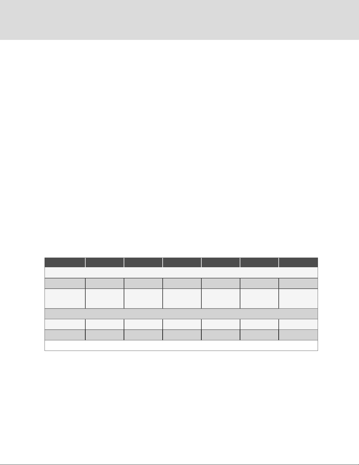
The Liebert® DS is a single component in the facility heat-removal system. The system includes air distribution (raised
floors, duct systems), outdoor heat rejection (condensers, pumps, drycoolers) and indoor cooling and humidity loads
(equipment load, location, outside air infiltration). Proper application and maintenance of the entire system is critical to the
life and reliability of the thermal-management units.
• Good maintenance practices are essential to minimizing operation costs and maximizing product life.
• Read and follow monthly and semi-annual maintenance schedules included in this manual. These MINIMUM
maintenance intervals may need to be more frequent based on site-specific conditions.
• See the Liebert®iCOM™ user manual, SL-31075, available at www.Vertiv.com, for instructions on using the
controller to predict some service maintenance intervals.
• We recommend the use of trained and authorized service personnel, extended service contracts and factoryspecified replacement parts. Contact your Vertiv sales representative.
10.1 Filters
NOTICE
Risk of improper filter installation. Can cause filter collapse and airflow reduction.
Pleat direction is non-standard. Use only short-pleat filters (see Figure 9.2 on page90). Long-pleat filters are subject to
collapse at high airflows.
To maximize the performance and reliability of the equipment, use only Vertiv filters. Contact your Vertiv representative to
order replacement filters.
Verify that filters are installed and positioned so the air-flow direction marked on the filter is the same direction as unit air
flow.
Table 9.1 Filter Quantities
035 042 053 070 077 105
Downflow Models
Quantity 3 3 4 4 4 4
Nominal Size, inches
UpflowModels (Front & Rear return)Filters located in separate filter box on rear return, located on lower unit panel
Quantity 4 4 6 6 6 8
Nominal Size, inches 25x 20 25x20 25x20 25x20 25x20 25x20
Disposable Type -Nominal Sizes and Quantities, Standard MERV 8 or Optional MERV 11; (filter types ca nnot be mixed, must be allMERV8or all MERV 11)
2 @ 25x20
1 @ 25x16
2 @ 25x20
1 @ 25x16
4 @ 25x20 4 @ 25x20 4 @ 25x20
2 @ 25x20
4 @ 25x1 6
10.1.1 Filter Replacement for Downflow Units
1. Disconnect power from the unit.
2. Open the front access panel, locate the filter above the electric panel, and slide the filter out the front of the
unit.
3. Replace with new filter—install the filter in the proper direction of the airflow.
4. Test the operation of the filter clog switch.
The unit panels must be in place and closed to find this point.
88
Vertiv | Liebert® DS ™ In staller/User Guide

5. Start the blower and turn the switch counterclockwise until the alarm is energized.
6. Turn the adjusting knob one turn clockwise or to the desired filter change point.
Figure 9.1 Proper Filter Pleat Direction
Item Description
1 Short pleat construction
2 Longpleat construction
10.1.2 Filter Replacement for Upflow Units
1. Disconnect power from the unit.
2. Open the front access panel and remove the filter(s).
• For upflow front return units, remove the lower front access panels, lift filters to the top of the filter rack
and tilt forward for removal.
• For upflow rear return units, remove filters using filter access door in rear return filter box.
3. Replace with new filter—install the filters in the proper direction of the airflow. The proper direction is marked
on the filter.
4. Test the operation of the filter clog switch.
The unit panels must be in place and closed to find this point.
10 Main tenan ce
89

5. Start the blower and turn the switch counterclockwise until the alarm is energized.
6. Turn the adjusting knob one turn clockwise or to the desired filter change point.
Figure 9.2 Proper Filter Pleat Direction
Item Description
1 Short pleat construction
2 Longpleat construction
90
Vertiv | Liebert® DS ™ In staller/User Guide

10.2 Blower Drive System—EC Fans
WARNING! Risk of electric shock. Can cause serious injury or death. Open all local and remote electric power
supply disconnect switches and verify with a voltmeter that power is off before working within the fan-motor
electric-connection enclosures. Fan-motor controls can maintain an electric charge for 10 minutes after
power is disconnected. Wait 10 minutes after power is verified as off before working within the electric
control/connection enclosures. Use only fully-trained and qualified HVAC technicians to perform
maintenance on the fans.
CAUTION: Risk of contact with high-speed rotating fan blades. Can cause serious injury or death. Open all
local and remote electric power-supply disconnect switches, verify with a voltmeter that power is off, and
verify that all fan blades have stopped rotating before working in the unit cabinet or on the fan assembly. If
control voltage is applied, the fan motor can restart without warning after a power failure. Do not operate the
unit with any or all cabinet panels removed. Do not operate upflow units without installing a plenum,
ductwork of gaurd over the blower opening(s) on the top surface of the unit cabinet. Ductwork must be
connected to the blower(s) or a plenum must be installed on the blower deck for protection from rotating
blower wheel(s) on upflow units.
CAUTION: Risk of improper moving, lifting and handling. Can cause equipment damage or injury. Only
properly trained and qualified personnel should work on this equipment. Evaporator fan modules weigh in
excess of 125-lb (56.7-kg). Use proper lifting techniques and wear appropriate, OSHA-approved PPE to avoid
injury and dropping the fan module during removal. Equipment used in handling/lifting, and/or installing the
fan assembly must meet OSHA requirements. Use handling/lifting equipment rated for the weight of the fan
assembly. Use ladders rated for the weight of the fan assembly and technicians if used during installation.
Refer to handling/lifting, and/or installation equipment operating manual for manufacturer's safety
requirements and operating procedures.
10 Main tenan ce
NOTICE
Risk of improper power-supply connection. Can cause equipment damage and loss of warranty coverage.
Prior to connecting any equipment to a main or alternate power source (for example: back-up generator
systems) for start-up, commissioning, testing, or normal operation, ensure that these sources are correctly
adjusted to the nameplate voltage and frequency of all equipment to be connected. In general, power-source
voltages should be stabilized and regulated to within ±10% of the load nameplate nominal voltage. Also, ensure
that no three-phase sources are single-phased at any time.
NOTICE
Risk of improper installation. Can cause equipment damage.
Only a properly trained and qualified technician should install or open this motor.
Use 60/75°C Class 1 copper wire only.
91

10.2.1 Protective Features
Monitoring functions protect the motor against overtemperature of electronics, overtemperature of motor and incorrect
rotor position detection. With any of these failures, an alarm will display through the Liebert® iCOM controller and the motor
stops electronically. There is no automatic restart. The power must be switched off for a minimum of 20 seconds once the
motor is at a standstill.
The motor also provides locked rotor protection, undervoltage/phase failure detection and motor current limitation. These
conditions will display an alarm through the Liebert® iCOM.
10.2.2 Fan Impellers and Bearings Maintenance
Fan impellers should be periodically inspected and any debris removed. Check to ensure that the impellers can rotate
freely and that the fan guards are still properly mounted for sufficient protection against accidentally contacting the
impeller. Bearings used on the units are maintenance-free. Consult the factory for more information.
10.2.3 Fan Assembly Troubleshooting
Any safety hazards stemming from the device must be re-evaluated once it is installed in the end device.
Do not make any modifications, additions or conversions to the fan assembly without the approval of Vertiv.
WARNING! Risk of electric shock. Can cause serious injury or death. Open all local and remote electric powersupply disconnect switches and verify with a voltmeter that power is off before opening the fan motor
electric-connection enclosure. Use only fully-trained and qualified HVAC technicians to replace or perform
maintenance on the EC fans.
WARNING! Risk of contact with high-speed rotating fan blades. Can cause serious injury or death. Open all
local and remote electric power-supply disconnect switches, verify with a voltmeter that power is off, and
verify that all fan blades have stopped rotating before working in the unit cabinet or on the fan assembly. If
control voltage is applied, the fan motor can restart without warning after a power failure. Do not operate the
unit with any or all cabinet panels removed.
CAUTION: Risk of exposure to harmful noise levels. Can cause hearing injury or loss. Depending on the
installation and operating conditions, a sound pressure level greater than 70dB(A) may arise. Take
appropriate technical safety measures. Operating personnel must wear appropriate, OSHA-approved PPE
and observe all appropriate hearing-protection safety requirements.
CAUTION: Risk of contact with hot surfaces. Can cause injury. The fan motor, and some electrical
components are extremely hot during unit operation. Allow sufficient time for them to cool to a touch-safe
temperature before working within the unit cabinet. Use extreme caution and wear appropriate, OSHAapproved PPE when working on or near hot components.
92
Vertiv | Liebert® DS ™ In staller/User Guide

Risk of improper power-supply connection. Can cause equipment damage and loss of warranty coverage.
Prior to connecting any equipment to a main or alternate power source (for example: back-up generator
systems) for start-up, commissioning, testing, or normal operation, ensure that these sources are correctly
adjusted to the nameplate voltage and frequency of all equipment to be connected. In general, power-source
voltages should be stabilized and regulated to within ±10% of the load nameplate nominal voltage. Also, ensure
that no three-phase sources are single-phased at any time.
NOTE: Do not assume that the fan blades will not start to spin. If the motor is in a fault condition, it will safely shut
down. Once the fault condition is cleared, there are certain conditions in which the motor will automatically resume
operation.
EC Fan Fault Conditions
Table 9.2 EC-fan Fault Conditions
Fault
Condition
Phase Failure Automatic
Locked/Blocked
Rotor
Hall Effect
Sensor Error
Motor O ver
Temperature
Electronics Ov er
Temperature
Line
Under-Voltage
Reset Trigger Description
Automatic The rotoris blocked. Once the locking mechanism has been remov ed, the motor will automatically restart.
Manual
(Mains/Software)
Manual
(Mains/Software)
Manual
(Mains/Software)
Automatic Once the line v oltage returns within permitted operating range, the fan willautomatically restart.
EC Fan High Voltage Tests
1. Check Fuses. If fuses are okay, perform the following:
• Check all connections.
• Make sure connections are on the wire strand and not on the wire insulation.
• Cycle Power. Disconnect mains voltage to power down the motor and then re-apply power.
• Check mains voltage at each phase (phase to ground) at the KL1 connector. Confirm phase failure
not present.
• Check that the voltage is within the acceptable voltage range at the KL1 connector. Confirm line
under-voltage is not present.
One phase is missing. In this case the motor will come to a stop and then automatically restart when all phases are
present.
The Hall Effect Sensor is used to monitor fan speed. If there is a hall sensor communication failure withthe
electronics, the motor will stop. In this case there has to be a manual restart (either with the ma ins power or
software).
The motor will stop in the event there is a motor over temperature condition. In this case there has to be a manual
restart (either with the ma ins power or software).
The motor will stop in the event there is an electronics over temperature condition. In this case there has to be a
manual restart (either with the mains power or software).
10 Main tenan ce
93

2. Check fuses. If fuses are blown, perform the following:
• Check resistances across the phases at the KL1 connector and note them in the following table..
NOTE: Power wires must be removed from the motor for resistance test.
Table 9.3 Resistances at KL1 Connector
L1 - L2 Figure 9.3 Ohm
L2 -L3 Ohm
L1 - L3 Ohm
• Resistances should be similar for all 3 readings.
• Resistance readings should be greater than 2Ohm.
• Check all connections. Make sure connections are on the wire strand and not on the wire
insulation.
• Replace fuses.
• Check mains voltage at each phase (phase to ground) at the KL1 connector. Confirms phase
failure not present.
Figure 9.4 KL1 Connector
• Check that the voltage is within the acceptable voltage range at the KL1 connector. Confirmsline
under-voltage is not present.
94
Vertiv | Liebert® DS ™ In staller/User Guide
 Loading...