

Page 1
Vaisala Ceilometer
CL31
USER'S GUIDE
M210482EN-B
October 2004
Page 2

PUBLISHED BY
Vaisala Oyj Phone (int.): +358 9 8949 1
P.O. Box 26 Fax: +358 9 8949 2227
FIN-00421 Helsinki
Finland
Visit our Internet pages at http://www.vaisala.com/
© Vaisala 2004
No part of this manual may be reproduced in any form or by any means,
electronic or mechanical (including photocopying), nor may its contents be
communicated to a third party without prior written permission of the copyright
holder.
The contents are subject to change without prior notice.
Please observe that this manual does not create any legally binding obligations for
Vaisala towards the customer or end user. All legally binding commitments and
agreements are included exclusively in the applicable supply contract or
Conditions of Sale.
Page 3

________________________________________________________________________________
Table of Contents
CHAPTER 1
GENERAL INFORMATION............................................................................7
About This Manual ................................................................... 7
Contents of This Manual ....................................................... 7
Related Manuals ................................................................... 8
Feedback............................................................................... 8
Safety......................................................................................... 8
General Safety Considerations ............................................. 8
Product Related Safety Precautions ..................................... 9
Laser Safety ........................................................................ 10
ESD Protection.................................................................... 11
Recycling ................................................................................ 12
Warranty..................................................................................12
CHAPTER 2
PRODUCT OVERVIEW................................................................................ 13
Introduction to Vaisala Ceilometer CL31............................. 13
Product Nomenclature........................................................... 15
CHAPTER 3
INSTALLATION............................................................................................ 19
Installation Procedure............................................................ 19
Unloading and Unpacking Instructions ............................... 19
Preparing a Concrete Foundation....................................... 20
Mounting the Ceilometer CL31 ...........................................22
Connecting the External Cables ......................................... 25
Data Line Connection.......................................................... 26
Grounding............................................................................ 28
Maintenance Terminal Connection .....................................29
Setting up Maintenance Terminal Connection............... 29
Operation of Maintenance Terminal Connection ........... 29
Using the Tilt Feature.......................................................... 29
Mobile Operation Aspects ................................................... 30
Startup..................................................................................... 31
Startup Procedure ............................................................... 31
Settings for Normal Operation ............................................ 34
Factory Settings of User Programmable Parameters ......... 35
CHAPTER 4
OPERATION................................................................................................. 37
Operation Modes .................................................................... 37
Serial Lines - Open and Closed Port .................................... 37
VAISALA ________________________________________________________________________ 3
Page 4

User's Guide ______________________________________________________________________
User Commands .....................................................................39
Data Messages........................................................................ 44
CL31 Data Messages No. 1 and 2 ......................................45
CRC16 Checksum..........................................................51
CL31 Status Message .........................................................52
CT12K Messages ................................................................ 55
CT12K Digital Message No. 2........................................ 55
CT12K Digital Message No. 3........................................ 59
CT25K Data Messages .......................................................60
CT25K Data Message No. 1 ..........................................60
CT25K Data Message No. 6 ..........................................62
CT25KAM Data Messages.................................................. 64
CT25KAM Data Message No. 60...................................64
CT25KAM Data Message No. 61...................................64
LD40 Standard Telegram ....................................................64
Telegram Structure Remarks .........................................66
Failure and Warning Messages .....................................66
Checksum Calculation....................................................69
Manual Message .................................................................70
Polling Mode ...........................................................................70
CHAPTER 5
FUNCTIONAL DESCRIPTION .....................................................................73
Theory of Operation ...............................................................73
Basic Principle of Operation ................................................ 73
Practical Measurement Signal.............................................74
Noise Cancellation ..............................................................74
Return Signal Strength ........................................................75
Height Normalization ...........................................................75
Backscatter Coefficient........................................................ 75
Extinction Normalization and Vertical Visibility....................77
CHAPTER 6
MAINTENANCE............................................................................................79
Periodic Maintenance............................................................. 79
Alarms and Warnings ..........................................................79
Window Cleaning.................................................................80
Calibration ......................................................................80
Checking the Door Gasket .................................................. 81
Battery Check ...................................................................... 81
Storage ................................................................................82
CHAPTER 7
TROUBLESHOOTING..................................................................................83
Accessing the Diagnostic Information.................................84
Equipment ...........................................................................84
Troubleshooting Instructions ............................................... 84
Warning and Alarm Messages ..............................................86
Technical Support .................................................................. 90
Vaisala Service Centers ......................................................... 90
4 ___________________________________________________________________ M210482EN-B
Page 5

________________________________________________________________________________
CHAPTER 8
REPAIR ........................................................................................................ 91
Replacing Window Assembly CLW311................................ 91
Replacing Ceilometer Laser Transmitter CLT311............... 93
Replacing Ceilometer Receiver CLR311.............................. 94
Replacing Ceilometer Engine Board CLE311.................... 100
Replacing No-break Battery 4592....................................... 101
Replacing AC Power CLP311.............................................. 102
Replacing Window Blower CLB311-115 / CLB 311-230.... 104
Replacing Ceilometer Optics CLO311................................ 105
Replacing Internal Heater CLH311-115 / CLH311-230 ......107
Replacing Internal Cable Set............................................... 109
Replacing Laser Monitor Board CLM311........................... 113
Replacing Modem Module DMX501 (Optional).................. 115
CHAPTER 9
TECHNICAL DATA .................................................................................... 117
Specifications ....................................................................... 117
Mechanical Specifications................................................. 117
External Connector J1 - Window Conditioner ................... 118
External Connector J2 - Power Input ................................ 118
Output Interface ................................................................ 118
External Connector J3 - Data Line............................... 119
External Connector J4 - Maintenance Line.................. 120
Modem Module DMX501 ..................................................121
Transmitter Specifications................................................. 121
Receiver Specifications..................................................... 122
Optical System Specifications........................................... 122
Performance Specifications .............................................. 122
Environmental Conditions Specifications.......................... 123
INDEX ......................................................................................................... 125
List of Figures
Figure 1 Vaisala Ceilometer CL31.......................................................... 14
Figure 2 Ceilometer CL31 Main Parts .................................................... 16
Figure 3 Measurement Unit Handle ....................................................... 20
Figure 4 Foundation Construction .......................................................... 21
Figure 5 Removing and Attaching the Measurement Unit ..................... 23
Figure 6 Mounting the Shield.................................................................. 24
Figure 7 External Connectors (Bottom View) ......................................... 25
Figure 8 Data Line Modem Connection.................................................. 26
Figure 9 Data Line RS-485 Connection ................................................. 27
Figure 10 Data Line RS-232 Connection ................................................. 28
Figure 11 Subassembly Interconnections ................................................ 32
Figure 12 CL31 Switches ......................................................................... 33
Figure 13 Ceilometer Engine Board CLE311 ........................................... 34
Figure 14 Operation Modes...................................................................... 37
Figure 15 Open and Closed Port.............................................................. 39
Figure 16 Typical Measurement Signal.................................................... 74
VAISALA ________________________________________________________________________ 5
Page 6

User's Guide ______________________________________________________________________
Figure 17 CL31 ......................................................................................... 96
Figure 18 Main Components of Ceilometer CL31 .................................... 98
Figure 19 Ceilometer Engine Board CLE311 ........................................... 99
Figure 20 Grounding Wires of the Internal Cable Set (top view)............ 110
Figure 21 Internal Heater Wiring and Connector at the Left of the Optics
Frame .....................................................................................111
Figure 22 Optics Frame with Cable Set..................................................112
Figure 23 Connecting Mains Filters to the Cable Set .............................112
Figure 24 DMX501..................................................................................116
Figure 25 Pin Connections of Connector J4 ........................................... 120
List of Tables
Table 1 Related Manuals......................................................................... 8
Table 2 Vaisala Ceilometer CL31 Main Parts .......................................15
Table 3 Vaisala Ceilometer CL31 Optional Parts..................................15
Table 4 Factory Defaults of User-Programmable Parameters ..............35
Table 5 User Level Commands .............................................................40
Table 6 Advanced Level Commands.....................................................43
Table 7 Messages with 10 m Resolution (Standard Mode)...................46
Table 8 Messages with 5 m Resolution (High Resolution)....................46
Table 9 Error Group Definition...............................................................67
Table 10 Error Group 1 (Byte 83) ............................................................67
Table 11 Error Group 2 (Byte 84) ............................................................67
Table 12 Error Group 3 (Byte 85) ............................................................67
Table 13 Error Group 4 (Byte 86) ............................................................68
Table 14 Error Group 5 (Byte 87) ............................................................68
Table 15 Error Group 6 (Byte 88) ............................................................ 68
Table 16 Error Group 7 (Byte 89) ............................................................68
Table 17 Command Telegram Description 'Polling Request' .................. 71
Table 18 Warnings...................................................................................86
Table 19 Alarms.......................................................................................88
Table 20 Miscellaneous Problems...........................................................89
Table 21 Ceilometer CL31 Mechanical Specifications.......................... 117
Table 22 Window Conditioner ...............................................................118
Table 23 Power Input.............................................................................118
Table 24 Data Line ................................................................................119
Table 25 Maintenance Line ................................................................... 120
Table 26 Modem Module DMX501 Specifications ................................121
Table 27 Transmitter Specifications ......................................................121
Table 28 Receiver Specifications ..........................................................122
Table 29 Optical System Specifications ................................................122
Table 30 Performance Specifications....................................................122
Table 31 Environmental Conditions Specifications ...............................123
6 ___________________________________________________________________ M210482EN-B
Page 7

Chapter 1 ________________________________________________________ General Information
CHAPTER 1
GENERAL INFORMATION
This chapter provides general notes for the product.
About This Manual
This manual provides information for installing, operating, and
maintaining Vaisala Ceilometer CL31.
Contents of This Manual
This manual consists of the following chapters:
- Chapter 1, General Information, provides general notes for the
product.
- Chapter 2, Product Overview, introduces the features, advantages,
and the product nomenclature.
- Chapter 3, Installation, provides you with information that is
intended to help you install this product.
- Chapter 4, Operation, contains information that is needed to
operate this product.
- Chapter 5, Functional Description, describes the functionality of
the product.
- Chapter 6, Maintenance, provides information that is needed in the
basic maintenance of the product.
- Chapter 7, Troubleshooting, describes common problems, their
probable causes and remedies, and gives the contact information.
- Chapter 8, Repair, explains how to remove and replace different
parts of Vaisala Ceilometer CL31.
VAISALA ________________________________________________________________________ 7
Page 8
User's Guide ______________________________________________________________________
- Chapter 9, Technical Data, provides the technical data of the
product.
- INDEX
Related Manuals
Table 1 Related Manuals
Manual Code Manual Name
M210310EN-A Termination Box User's Guide
Feedback
Vaisala Customer Documentation Team welcomes your comments
and suggestions on the quality and usefulness of this publication. If
you find errors or have other suggestions for improvement, please
indicate the chapter, section, and page number. You can send
comments to us by e-mail: manuals@vaisala.com
Safety
WARNING
CAUTION
General Safety Considerations
Throughout the manual, important safety considerations are
highlighted as follows:
Warning alerts you to a serious hazard. If you do not read and follow
instructions very carefully at this point, there is a risk of injury or
even death.
Caution warns you of a potential hazard. If you do not read and
follow instructions carefully at this point, the product could be
damaged or important data could be lost.
NOTE
8 ___________________________________________________________________ M210482EN-B
Note highlights important information on using the product.
Page 9

Chapter 1 ________________________________________________________ General Information
WARNING
WARNING
Failure to comply with these precautions or with specific warnings
elsewhere in this manual violates safety standards of design,
manufacture, and intended use of the instrument. Vaisala Oyj
assumes no liability for the customer's failure to comply with these
requirements.
Product Related Safety Precautions
Vaisala Ceilometer CL31 delivered to you has been tested for safety
and approved as shipped from the factory. The following safety
precautions must be observed during all phases of operation, service,
and repair of this instrument:
To minimize shock hazard, the instrument chassis and cabinet must
be connected to an electrical ground. The instrument is equipped
with a three-conductor AC power connector. The power cable must
either be plugged into an approved three-contact electrical outlet or
the instrument must be carefully grounded to a low-resistance safety
ground.
WARNING
WARNING
WARNING
Do not operate the instrument in the presence of flammable gases or
fumes. Operation of any electrical instrument in such an environment
constitutes a definite safety hazard.
Do not attempt internal service or adjustment unless another person,
capable of rendering first aid and resuscitation, is present.
Because of the danger of introducing additional hazards, do not
install substitute parts or perform any unauthorized modification to
the instrument. Return the instrument to a Vaisala office or
authorized Depot for service and repair to ensure that safety features
are maintained.
VAISALA ________________________________________________________________________ 9
Page 10
User's Guide ______________________________________________________________________
WARNING
WARNING
Operating personnel must not remove instrument covers. Component
replacement and internal adjustments must be made by qualified
maintenance personnel. Do not replace components with the power
cable connected. Under certain conditions, dangerous voltages may
exist even with the power cable removed. To avoid injuries, always
disconnect power and discharge circuits before touching them.
High voltage will be present when the Laser Transmitter CLT311 or
Receiver CLR311 covers are removed and they are connected to a
powered unit. High voltage is present in AC Power Unit CLP311,
Internal Heater CLH311, Ceilometer Engine Board CLE311, and the
Window Blower CLB311 at the top of the Shield.
Laser Transmitter CLT311, Receiver CLR311, and AC Power Unit
CLP311 are equipped with the following warning label:
WARNING! HIGH VOLTAGE INSIDE THIS
ENCLOSURE
Internal Heater CLH311 can be hot and is equipped with the following
warning labels:
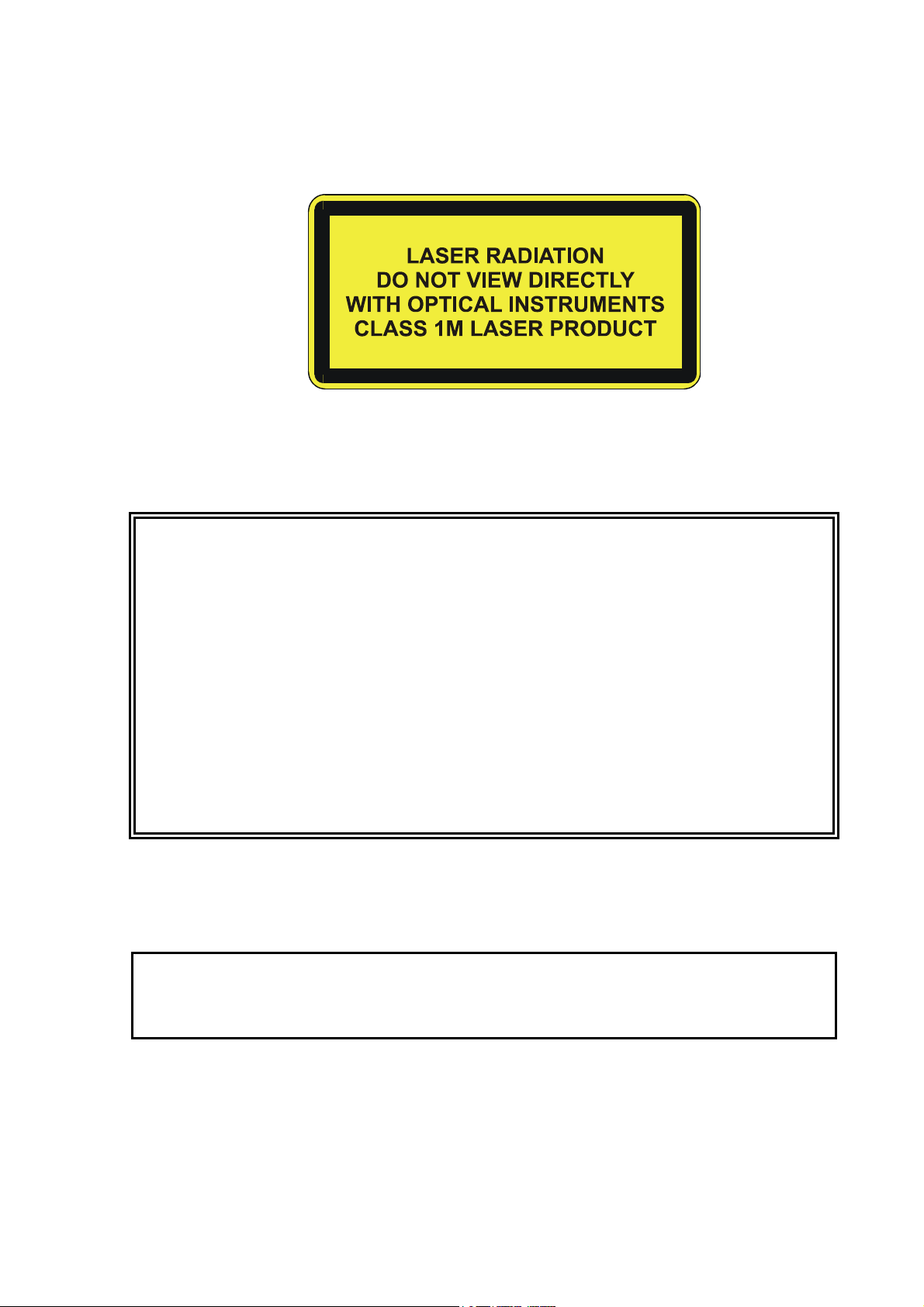
Laser Safety
Vaisala Ceilometer CL31 is classified as a Class 1M laser device in
accordance with International Standard IEC/EN 60 825-1. Complies
with 21 CFR 1040.10 and 1040.11 except for the deviations pursuant
to the Laser Notice No. 50, dated July 26, 2001. This means that
when CL31 is installed in a field environment with instrument covers
on and pointed vertically or near-vertically, it poses no established
biological hazard to humans.
10 __________________________________________________________________ M210482EN-B
Page 11
Chapter 1 ________________________________________________________ General Information
The device is equipped with the following label:
Ceilometer CL31 is intended for operation in an area restricted from
public access, and to be pointed vertically or near-vertically. The
following precautions must be followed during the service and
maintenance of the instrument:
WARNING
CAUTION
Never look directly into the Ceilometer Transmitter or Ceilometer
Optics with magnifying optics (such as glasses, binoculars, and
telescopes). Never remove the Ceilometer Transmitter from its
normal position without first switching off both the line and the
battery power and detaching the trasnmitter ribbon cable from the
Ceilometer Engine Board.
When operating, avoid looking at the ceilometer unit from the beam
direction. When tilting the unit, make sure that it is not being viewed
from the beam direction with magnifying optics.
Only trained personnel should perform maintenance functions.
Access to the work area by unauthorized persons during service
operations must be prevented.
ESD Protection
The equipment contains parts and assemblies sensitive to damage by
Electrostatic Discharge (ESD). Use ESD precautionary procedures
when touching, removing or inserting.
Electrostatic Discharge (ESD) can cause immediate or latent damage
to electronic circuits. Vaisala products are adequately protected
against ESD for their intended use. However, it is possible to damage
VAISALA _______________________________________________________________________ 11
Page 12
User's Guide ______________________________________________________________________
the product by delivering electrostatic discharges when touching,
removing, or inserting any objects inside the equipment housing.
To make sure you are not delivering high static voltages yourself:
- Handle ESD sensitive components on a properly grounded and
protected ESD workbench. When this is not possible, ground
yourself to the equipment chassis before touching the boards.
Ground yourself with a wrist strap and a resistive connection cord.
When neither of the above is possible, touch a conductive part of
the equipment chassis with your other hand before touching the
boards.
- Always hold the boards by the edges and avoid touching the
component contacts.
Recycling
Warranty
Recycle all applicable material.
Dispose of batteries and the unit according to statutory regulations.
Do not dispose of with regular household refuse.
For certain products Vaisala normally gives a limited one-year
warranty. Please observe that any such warranty may not be valid in
case of damage due to normal wear and tear, exceptional operating
conditions, negligent handling or installation, or unauthorized
modifications. Please see the applicable supply contract or Conditions
of Sale for details of the warranty for each product.
12 __________________________________________________________________ M210482EN-B
Page 13

Chapter 2 __________________________________________________________ Product Overview
CHAPTER 2
PRODUCT OVERVIEW
This chapter introduces the features, advantages, and the product
nomenclature.
Introduction to Vaisala Ceilometer CL31
Vaisala Ceilometer CL31 measures cloud height and vertical
visibility. The small and lightweight measurement unit suits well for
mobile operation.
Ceilometer CL31 employs pulsed diode laser LIDAR technology
(LIDAR = Light detection and ranging), where short, powerful laser
pulses are sent out in a vertical or near-vertical direction. The
reflection of light - backscatter - caused by haze, fog, mist, virga,
precipitation, and clouds is measured as the laser pulses traverse the
sky. The resulting backscatter profile, that is, the signal strength
versus the height, is stored and processed and the cloud bases are
detected. Knowing the speed of light, the time delay between the
launch of the laser pulse and the detection of the backscatter signal
indicates the cloud base height.
Ceilometer CL31 is able to detect three cloud layers simultaneously. If
the could base is obscured due to precipitation or ground-based fog,
CL31 reports vertical visibility. No adjustments in the field are
needed. The embedded software includes several service and
maintenance functions and gives continuous status information from
internal monitoring. The software is designed to give the full
backscatter profile.
To make Ceilometer CL31 easier to use and to ease the transfer from
old ceilometer versions to this new one, CL31 includes data messages
used in CT12K, CT25K, CT25KAM, and LD40.
VAISALA _______________________________________________________________________ 13
Page 14
User's Guide ______________________________________________________________________
0406-052
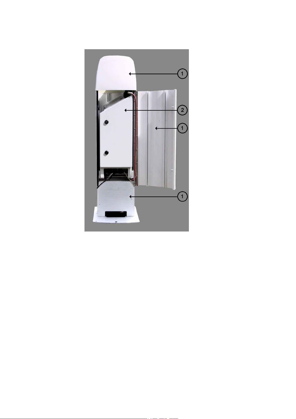
Figure 1 Vaisala Ceilometer CL31
The following numbers refer to Figure 1 above:
1 = Shield
2 = Measurement Unit
14 __________________________________________________________________ M210482EN-B
Page 15

Chapter 2 __________________________________________________________ Product Overview
Product Nomenclature
Table 2 Vaisala Ceilometer CL31 Main Parts
Code Common Name Description
CLO311 Optics Unit
CLW311 Window Assembly Spare part
CLT311SP Ceilometer Transmitter Spare part
CLR311 Ceilometer Receiver Spare part
CLM311 Laser Monitor Board Spare part
CLE311SP Ceilometer Engine Board Spare part
CLP311 AC Power Spare part
4592 No-break Battery Spare part
CLH311-115SP Inside Heater (100 ... 115 VAC) Spare part
CLH311-230SP Inside Heater (220 ... 240 VAC) Spare part
CLB311-115SP Window Blower (100 ... 115 VAC) Spare part
CLB311-230SP Window Blower (220 ... 240 VAC) Spare part
CT3839SP Power cable (230 V) Spare part
CT35324SP Power cable (115 V) Spare part
CT3838 Data cable Spare part
DRW217429 Coaxial Cable Spare part
Table 3 Vaisala Ceilometer CL31 Optional Parts
Code Common Name Description
DMX501 Modem Module Spare part
CLRADIOKIT Radio Modem Installation Kit Excl. radio modem
and antenna
TERMBOX-1200 Termination box, Mains and
signal
QMZ101 Maintenance cable
PSION Maintenance terminal
(palmtop computer)
CLTERMHOOD Optical Termination Hood
CT35022 Shock Absorber For ship
HMP50 UAB1A1A Internal Humidity Transmitter
For extended
surge and
overvoltage
protection
installations
The complete delivery also includes mating cables with connectors for
power and communication, installation hardware, a key for the
measurement unit door, and this CL31 User's Guide.
VAISALA _______________________________________________________________________ 15
Page 16
User's Guide ______________________________________________________________________
0311-057
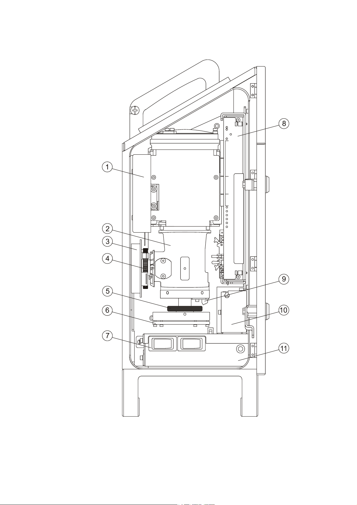
Figure 2 Ceilometer CL31 Main Parts
16 __________________________________________________________________ M210482EN-B
Page 17

Chapter 2 __________________________________________________________ Product Overview
The following numbers refer to Figure 2 on page 16:
1 = Internal heater CLH311
2 = CLO311 Optics unit
3 = Ceilometer Receiver CLR311
4 = Receiver ring
5 = Transmitter ring
6 = Ceilometer Transmitter CLT311
7 = F1 Main circuit breaker
F2 Window blower circuit breaker
8 = Ceilometer Engine Board CLE311
9 = Laser Monitor Board CLM311
10 = Battery 4592
11 = AC Power CLP311
12 = Battery switch
VAISALA _______________________________________________________________________ 17
Page 18

User's Guide ______________________________________________________________________
This page intentionally left blank.
18 __________________________________________________________________ M210482EN-B
Page 19

Chapter 3 _______________________________________________________________ Installation
CHAPTER 3
INSTALLATION
This chapter provides you with information that is intended to help
you install this product.
Installation Procedure
This section describes the installation procedure of Vaisala Ceilometer
CL31.
Unloading and Unpacking Instructions
CL31 is shipped in one container that contains the shield, the
measurement unit inside the shield, and all the equipment, accessories,
and documentation needed for carrying out the installation. Store the
original packaging for possible later transport need.
For opening, the package should be placed on a flat surface with the
indicated top side up. You should open the container from the top side
and carefully remove the ceilometer and all the other equipment.
- Use proper gloves for protection against sharp edges, etc.
- Avoid touching the window or lens surfaces, unless you plan to
clean them properly afterwards.
- Keep the integral protective caps on the unused external connectors
(J4 Maintenance line).
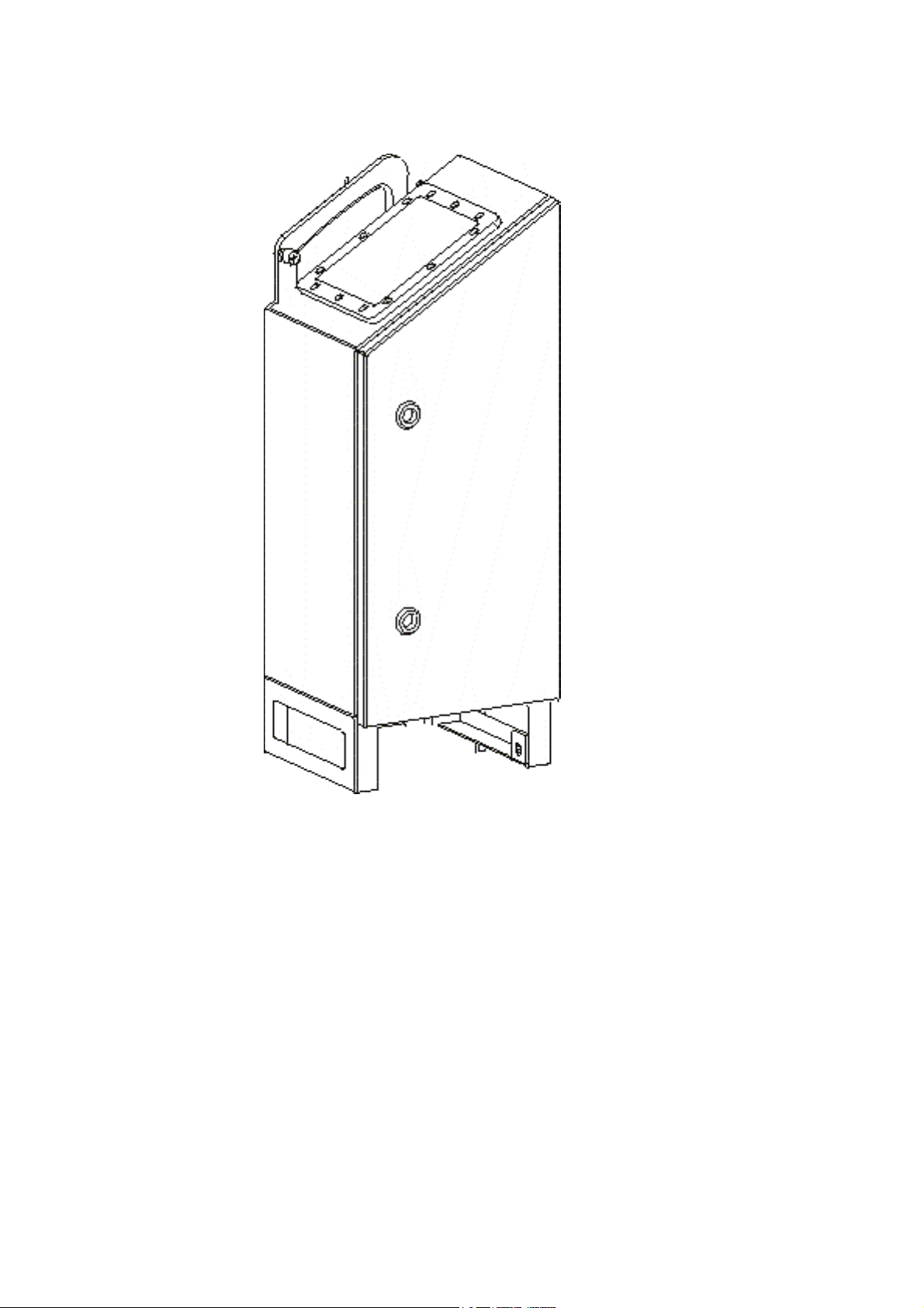
- Use the measurement unit handle for lifting and carrying the
measurement unit. See Figure 3 on page 20.
VAISALA _______________________________________________________________________ 19
Page 20
User's Guide ______________________________________________________________________
0311-054
Figure 3 Measurement Unit Handle
If mishandling occurs during transit or installation, the instrument
should be returned to a Vaisala office or authorized Depot for
inspection.
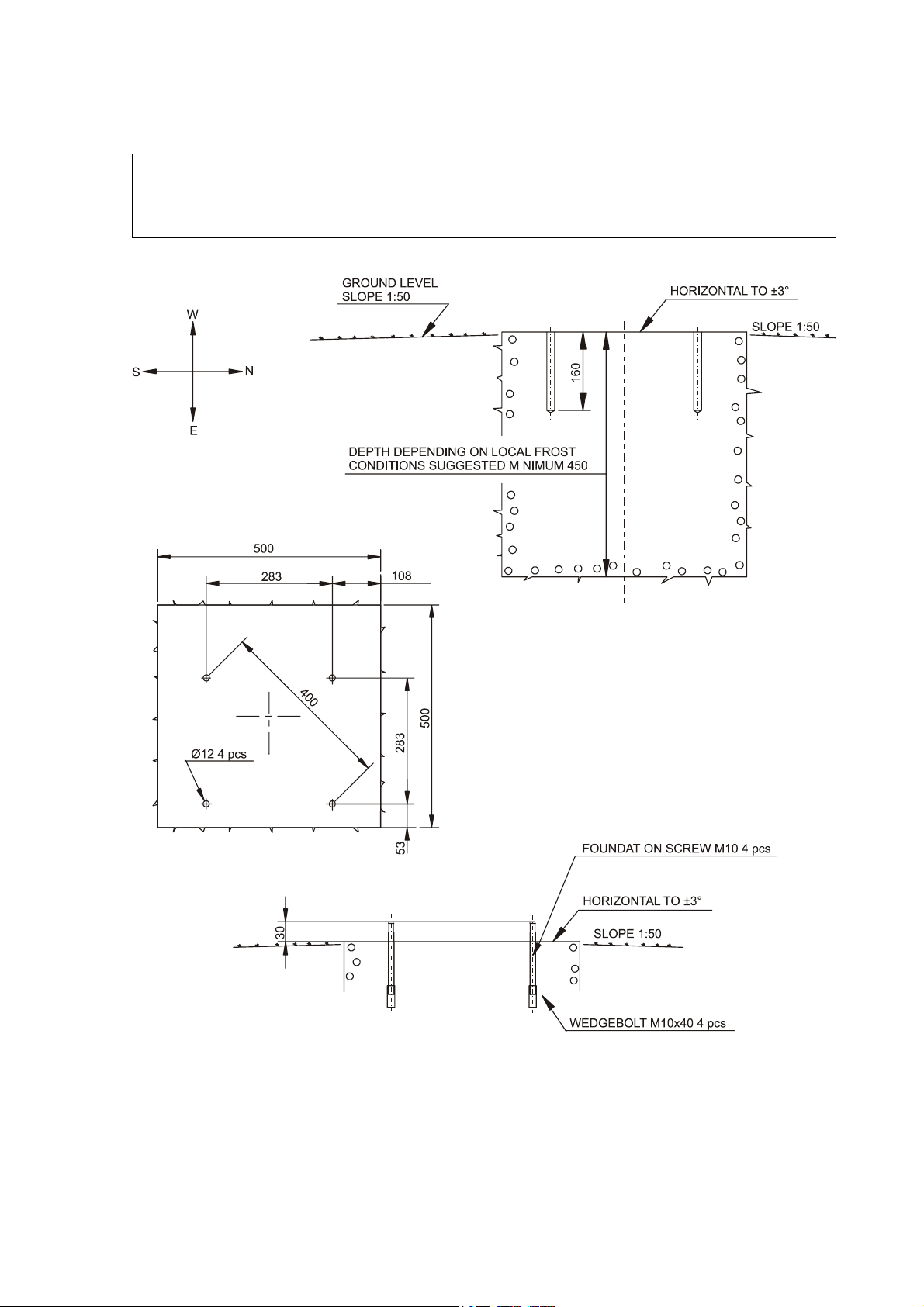
Preparing a Concrete Foundation
The standard foundation for the CL31 ground installation is a concrete
foundation. The minimum dimensions suggested are presented in
Figure 4 on page 21. Mounting hardware is included with the delivery.
20 __________________________________________________________________ M210482EN-B
Page 21
Chapter 3 _______________________________________________________________ Installation
NOTE
In case CL31 is used to replace another ceilometer (CT25K, CT12K,
LD40, LD25, or LD12) the existing foundation and foundation
screws can be used.
9412-027
Figure 4 Foundation Construction
VAISALA _______________________________________________________________________ 21
Page 22

User's Guide ______________________________________________________________________
There are two alternative ways to create a concrete foundation for
Ceilometer CL31. You can either cast a new concrete foundation or
use an existing one.
NOTE
If the tilt feature will be used (see section Using the Tilt Feature on
page 29), observe this in the layout of the foundation screws and
shield placement.
Creating a New Concrete Foundation
1. Fasten the M10 × 40 wedge bolts to the lower ends of the
foundation screws (4 each).
2. Fix a drilling template to the upper ends of the foundation
screws with nuts.
3. Place the template with the attached foundation screws into the
hole in such a way that approximately 30 mm (1.25 inches) of
the foundation screw threads stand above the surface.
4. Pour in the concrete and finish the foundation.
Using an Existing Foundation
1. Drill four holes with a diameter of 12 mm and a depth of
165 mm (0.5 × 6.5 inches) into the concrete.
2. Fasten the M10 × 40 wedge bolts to the lower ends of the
foundation screws (4 each).
3. Place the wedge bolt and foundation screw combinations into
the holes, with the wedge bolts down, and hammer the
protruding threads down.
4. Tighten the foundation screws a few turns to attach the wedge
bolts to the hole walls.
Mounting the Ceilometer CL31
Ceilometer CL31 is delivered with the measurement unit attached to
the shield. If two people are handling the installation, the shield can be
mounted with the measurement unit attached. It is, however,
recommended that you first remove the measurement unit, mount the
shield, and then reattach the measurement unit to the shield.
22 __________________________________________________________________ M210482EN-B
Page 23
Chapter 3 _______________________________________________________________ Installation
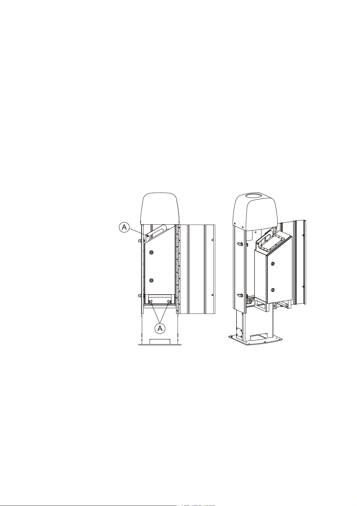
To mount Ceilometer CL31, proceed as follows:
1. Remove the measurement unit from the shield. To do this,
loosen the three attachment screws (marked A in Figure 5
below), disconnect the blower cable from connector J1 (see
Figure 7 on page 25), and pull out the unit.
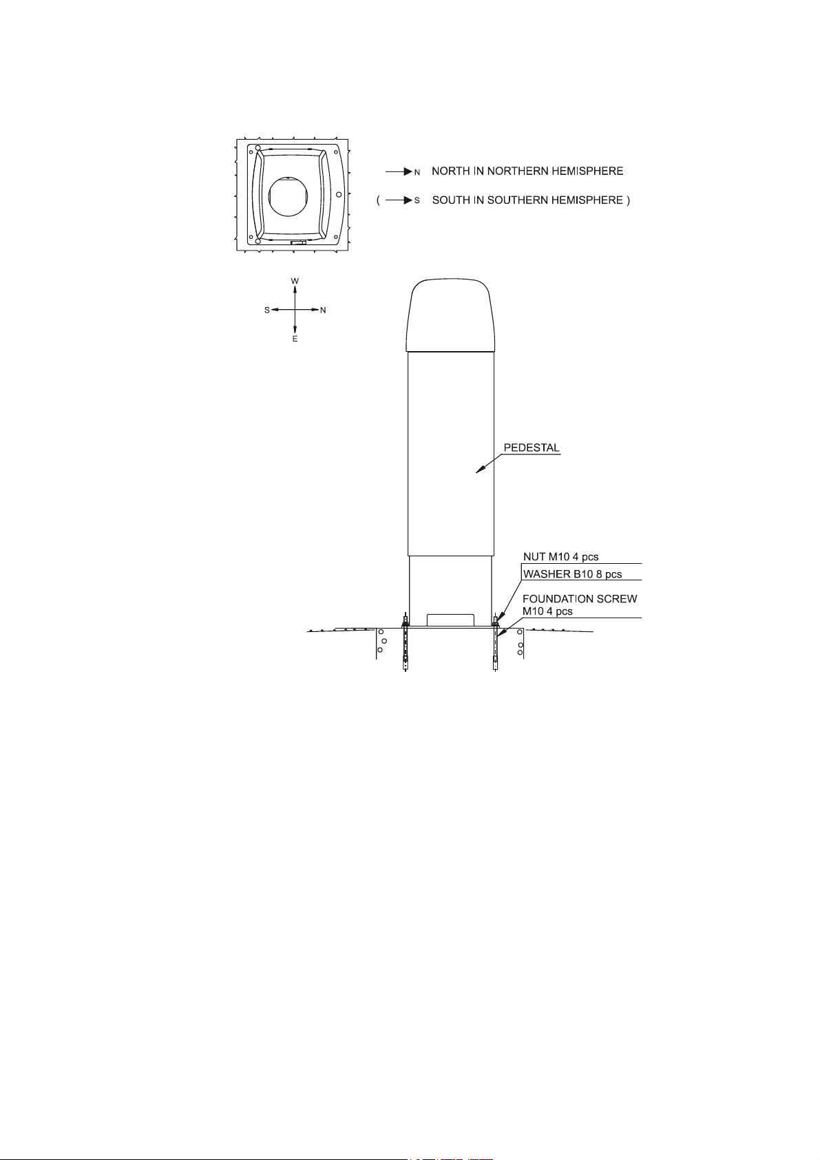
2. Place the shield on the foundation in such a way that the door
faces North in the Northern hemisphere and South in the
Southern hemisphere. Refer to Figure 6 on page 24.
3. Place the flat washers on the foundation screws and fix the nuts.
Refer to Figure 6 on page 24.
4. Place the measurement unit inside the shield, connect the blower
cable to connector J1, and tighten the three attachment screws
(marked A in Figure 5 below).
0311-055
Figure 5 Removing and Attaching the Measurement Unit
VAISALA _______________________________________________________________________ 23
Page 24
User's Guide ______________________________________________________________________
0311-056
Figure 6 Mounting the Shield
24 __________________________________________________________________ M210482EN-B
Page 25

Chapter 3 _______________________________________________________________ Installation
Connecting the External Cables
All external connectors to the measurement unit are located at the
bottom front edge as seen from the door direction. Figure 7 below
shows the external connectors J1, J2, J3, and J4.
0306-006
Figure 7 External Connectors (Bottom View)
The window blower mounted into the shield is connected to connector
J1. Line power input is connected to connector J2. Remote
communication is normally connected to connector J3. A local
maintenance terminal, a laptop or a palmtop for example, can be
connected to connector J4. A protective cap is included for covering
J4 when it is not used.
External mating connectors with 2 m (7 ft) cable are included for J2
and for J3. The power plug of the J2 cable can be cut when the unit is
permanently installed at the final site.
VAISALA _______________________________________________________________________ 25
Page 26

User's Guide ______________________________________________________________________
The wire connections and cable glands of the optional Termination
Box are presented in the Termination Box User's Guide (refer to
section Related Manuals on page 8).
NOTE
When the permanent line power installation is made, the maximum
size of the fuse protecting the power line is 10 A.
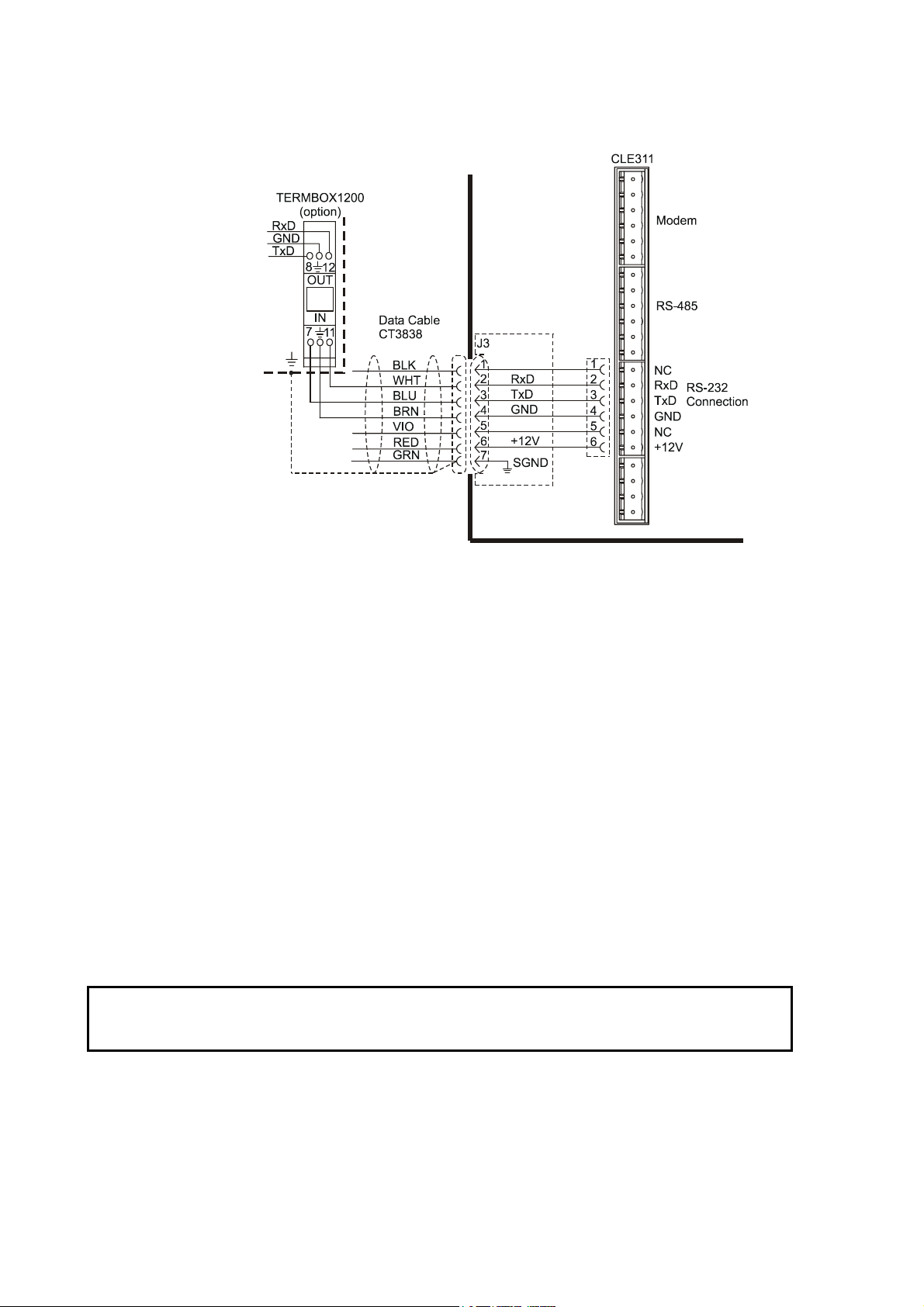
Data Line Connection
Vaisala Ceilometer CL31 offers three possible options for the data line
connection. These options are presented in the following figures.
0311-060
Figure 8 Data Line Modem Connection
26 __________________________________________________________________ M210482EN-B
Page 27

Chapter 3 _______________________________________________________________ Installation
Default Settings for the Data Line Modem Connection
Modem mode V.22bis
Bit rate 2400
Data bits 8
Stop bits 1
Parity None
0311-061
Figure 9 Data Line RS-485 Connection
Default Settings for the Data Line RS-485 Connection
Bit rate 19200
Data bits 8
Stop bits 1
Parity None
VAISALA _______________________________________________________________________ 27
Page 28
User's Guide ______________________________________________________________________
0311-062
CAUTION
Figure 10 Data Line RS-232 Connection
Default Settings for the Data Line RS-232 Connection
Bit rate 19200
Data bits 8
Stop bits 1
Parity None
Handshake None
Grounding
The power supply connector J2 provides a standard protective ground
for the instrument chassis.
CL31 is equipped with a separate grounding screw for external
grounding at the bottom of the shield.
Connection to a solid earth ground at the installation site is
mandatory for adequate lightning and transient protection.
28 __________________________________________________________________ M210482EN-B
Page 29

Chapter 3 _______________________________________________________________ Installation
Maintenance Terminal Connection
Any terminal or PC with a serial interface and a terminal emulation
program can be used for operation and maintenance of Ceilometer
CL31. The maintenance terminal connection is established with the
QMZ101 maintenance cable, which connects the RS-232 port of the
PC to the maintenance port of the ceilometer.
A standard maintenance terminal option includes a PSION Palmtop
Computer and its Technical Manuals.
Setting up Maintenance Terminal Connection
1. Connect the RS cable to the ceilometer maintenance port
(connector J4) and the terminal computer.
2. Set the following settings for the terminal:
Bit rate 9600
Data bits 8
Stop bits 1
Parity None
Handshake None
Operation of Maintenance Terminal Connection
To operate the connection, do the following:
1. Turn the power on in CL31.
2. Open the CL31 maintenance with the open command.
3. The prompt CEILO > appears. For details, see Chapter 5,
Functional Description, on page 73.
Using the Tilt Feature
Ceilometer CL31 is designed to allow operation in a tilted direction.
The built-in tilt angle sensor detects the tilt angle, that is, the deviation
from vertical. The tilt feature allows three tilt angles: vertical, 12
degrees with the measurement unit door upwards, and 12 degrees with
the measurement unit door downwards. The cosine of the tilt angle is
used for an automatic correction of the detected cloud base height,
which enables accurate cloud base measurements also in a tilted
direction.
VAISALA _______________________________________________________________________ 29
Page 30
User's Guide ______________________________________________________________________
The tilt feature provides the following advantages:
- Protection in heavy weather conditions:
Using a tilt angle of 12 degrees protects the measurement unit
window from precipitation, thus enhancing the performance in
heavy weather conditions.
- Precision in aircraft approach detection:
The beam can be directed towards a direction that better represents
the approach of an aircraft than the straight vertical. This is useful,
for example, for helicopter approaches, and sites where the
ceilometer cannot be located exactly at the desired spot.
WARNING
NOTE
When tilting the unit, make sure that nobody is watching it with
binoculars or other magnifying optics.
To avoid direct sunlight, tilt the unit away from the sun. That is, tilt it
north in the northern hemisphere and south in the southern
hemisphere. Direct insolation exposure will not damage the unit but
will cause alarms and temporarily invalidate the data
As these advantages may be contradictory or cannot be realized
simultaneously, the user must decide the direction of the final
installation.
Mobile Operation Aspects
The small and lightweight measurement unit of Ceilometer CL31 is
also suitable for mobile operation. It has a built-in 12 V battery, which
enables operation without external power supply for about an hour in
normal room temperature.
NOTE
30 __________________________________________________________________ M210482EN-B
For switching the CL31 power fully off, also turn off the battery
switch in addition to the line power switch. Having the unit on with
the battery supply will only drain the battery.
Page 31

Chapter 3 _______________________________________________________________ Installation
NOTE
Startup
Do not attempt to carry a fully assembled unit alone, preferably, lift
the measurement unit from the shield. The two main parts, the
measurement unit (12 kg) and the shield (18.5 kg), can be lifted and
carried separately.
This section describes the different aspects of Ceilometer CL31 that
need to be considered before starting up the device.
Startup Procedure
Open the unit door with the key included in the delivery. Make a
visual check of the internal connectors and subassemblies (refer to
Figure 11 on page 32 for further information if necessary). Then
proceed as follows:
1. Turn the main circuit breaker F1 to the Off position (for
location, see Figure 12 on page 33).
NOTE
WARNING
2. Plug in the line supply cable to connector J2 (for location, see
Figure 7 on page 25) after checking the voltage of the power
supply cable connector.
3. Turn the Main Circuit Breaker F1, the Window Blower Circuit
Breaker F2, and the Battery Switch to the On position. After the
initialization routines, the Laser on LED starts blinking at
2-second intervals. Also the six diagnostic LEDs light up. For
location of the LEDs and switches, refer to Figure 12 on page 33
and Figure 13 on page 34.
For switching the CL31 power fully off, also turn off the battery
switch in addition to the line power switch. Having the unit on with
the battery supply will drain the battery.
Make sure that nobody is viewing the unit from the beam direction
with magnifying optics.
VAISALA _______________________________________________________________________ 31
Page 32

User's Guide ______________________________________________________________________
0311-058
Figure 11 Subassembly Interconnections
32 __________________________________________________________________ M210482EN-B
Page 33

Chapter 3 _______________________________________________________________ Installation
The following numbers refer to Figure 11 on page 32:
1 = Data line connection to AC power CLP311
2 = Coaxial cable connection to Ceilometer Receiver CLR311
3 = Connection to Ceilometer Transmitter CLT311
4 = Connection to Battery 4592
5 = Connection to Ceilometer Receiver CLR311
6 = Connection to Laser monitor board CLM311
7 = Connection to AC power CLP311
8 = Connection to Internal heater CLH311
9 = Battery switch
0406-053
Figure 12 CL31 Switches
The following numbers refer to Figure 12 above:
1 = F1 Main circuit breaker
2 = F2 Heater/Blower circuit breaker
VAISALA _______________________________________________________________________ 33
Page 34
User's Guide ______________________________________________________________________
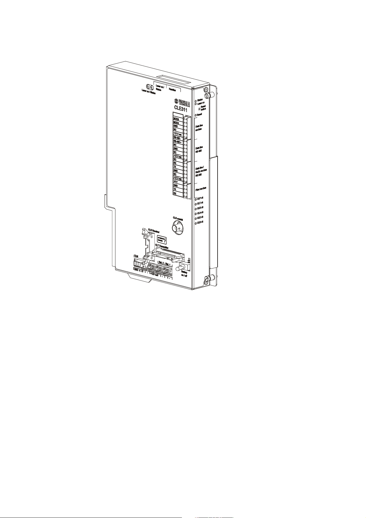
0311-059
Figure 13 Ceilometer Engine Board CLE311
Settings for Normal Operation
The switch settings for normal operation are as follows:
Main circuit breaker F1 ON
Heater/Blower circuit breaker F2 ON
Battery switch ON
The data message and interface configuration and the configuration of
measuring interval and transmission speed are standard factory
settings. When required, the settings can be changed by giving
commands with the terminal.
34 __________________________________________________________________ M210482EN-B
Page 35

Chapter 3 _______________________________________________________________ Installation
During the factory alignment procedure, the optical adjustments are
carefully carried out to fulfill the requirements and specifications of
the device. Optical adjustments have been made at the factory or
depot, thus there is no need to readjust them in the field.
Factory Settings of User Programmable Parameters
Table 4 below lists the factory defaults of user-programmable
parameters. The prevailing parameter settings of Ceilometer CL31 can
be seen with the following command:
get params parameter_group
The user-programmable parameters can be changed with the
following command:
set parameter_group parameter
Table 4 Factory Defaults of User-Programmable Parameters
Parameter Factory Default
Control blower Auto
Control inheater Auto
Data_acq power_save Disabled
Data_port baud 19200
Data_port mode RS232
Data_port parity 8N1
Maint_port baud 9600
Maint_port parity 8N1
Message angle_corr On
Message transmission Periodic
Message transmission delay 100 ms
Message height_offset 0
Message interval 2 s
Message port Data
Message profile scale 1.0
Message profile noise h2 Off
Message type msg2_20x385
Message units Feet
Message vv_limit ceiling 2000 m (6562 ft)
Message vv_limit sky_cond_percent 50
Oper_mode Normal
Port_timeout 2 min
Unit_id 0 (zero)
VAISALA _______________________________________________________________________ 35
Page 36

User's Guide ______________________________________________________________________
This page intentionally left blank.
36 __________________________________________________________________ M210482EN-B
Page 37

Chapter 4 ________________________________________________________________ Operation
CHAPTER 4
OPERATION
This chapter contains information that is needed to operate this
product.
Operation Modes
There are two operation modes, normal and standby. The set
oper_mode normal and set oper_mode standby commands are used
to switch between the modes. In the normal mode, continuous
measurement and message transmission occurs according to the
chosen parameters. The standby mode, which involves turning off the
wearing parts, can be used during periods when measurement is not
needed.
Figure 14 Operation Modes
Serial Lines - Open and Closed Port
0406-020
The two serial lines provided are called the maintenance line (external
connector J4) and the data line (external connector J3). The data line is
intended to be used for measurement data communication and can be
operated through a modem or baseband. The maintenance line is
intended for on-site maintenance access, and is used only as a
baseband. However, functionally the operation of the lines is identical,
VAISALA _______________________________________________________________________ 37
Page 38

User's Guide ______________________________________________________________________
the same commands, operations, and messages operate through any of
the lines, and the following description applies to both of them.
The factory default setting is 8 data bits, No parity, 1 Stop bit, and for
baseband lines, 9600 maint, 19200 data. The bit rate can be selected
from the user menu.
Both use the 7-bit USASCII character format. Both the UPPER and
lower letter cases can be used.
The standard operation of the serial lines requires no handshake
signals.
A communication port, in other words the serial line, has the
following two internal states (Figure 15 on page 39):
- CLOSED: This is the measurement data message transmitting state.
In this state, messages are transmitted as a response to a polling
input string or automatically at predetermined intervals, depending
on the corresponding settings (message transmission). User
commands are not accepted, except for the open command, which
turns the line into the OPEN state.
NOTE
- OPEN: This is the user dialog state. In this state, the user
commands are responded to and command input is echoed. A
command prompt CEILO > is displayed to indicate that CL31 is
ready for command input from the user. The commands are
executed by pressing ENTER, for example, OPEN 1 <enter>. No
automatic transmission of the measurement data message is
executed in the open state. The port reverts to the closed state with
the close command. An automatic, 2-minute time-out after the last
character input is applied. A 2 to 30-minute time-out may be set
with the set port_time_out command.
Only one of the ports can be open for commands at a time. Only one
of the ports transmits measurement messages at a time. Additionally,
in the RS-485 mode, a unit ID must be given with the open
command.
38 __________________________________________________________________ M210482EN-B
Page 39

Chapter 4 ________________________________________________________________ Operation
0406-066
Figure 15 Open and Closed Port
User Commands
User commands are described in Table 5 on page 40. User commands
are accessible after opening the line with the open command. No
password is needed.
The exact format of commands does not have to be remembered, as
the command line interpreter provides interactive support. At each
menu level, pressing ENTER provides an output of the available
menu. Inserting a letter followed by ENTER outputs all commands
starting with that letter. Inserting two letters followed by ENTER
outputs all commands that start with those two letters, etc., until only
the desired command is left. This command is then executed by
pressing the ENTER key.
In addition to the user menu and the user level command set, there is a
second in-depth maintenance and service level menu and command
set, which is intended for more profound system changes and
diagnostics. These advanced level commands are presented in a
separate table (see Table 6 on page 43). The password for this level is
"advanced". The commands on this level should only be used
according to the instructions in this manual.
VAISALA _______________________________________________________________________ 39
Page 40

User's Guide ______________________________________________________________________
Table 5 User Level Commands
Command Description
close Closes a user interface. Releases a port for message
transmission.
get diag contamination Prints diagnostic history of window contamination.
get diag angle Prints diagnostic history of inclinometer angle.
get diag battery Prints diagnostic history of battery voltage.
get diag int_temp Prints diagnostic history of internal temperature.
get diag l_power Prints diagnostic history of laser power.
get diag l_temp Prints diagnostic history of laser temperature.
get failure history Prints history of alarm and warning status.
get failure status Shows active alarms and warnings.
get params data_acq Prints data-acquisition related parameters.
get params factory Prints factory calibration values.
get params message Prints message related parameters.
get params port Prints serial port and modem parameters.
get sensors Prints data-acquisition values, tilt angles, and
humidity, if available.
get temperatures Displays temperatures.
get uptime Displays uptime clock.
get voltages Displays voltages.
name Displays device type, name, and ID.
open Opens a user interface.
reset Resets the ceilometer using the watchdog reset.
set control blower on Sets the window blower on.
set control blower off Sets the window blower off.
set control blower manual Sets manual control.
set control blower auto Sets automatic control.
set control inheater on Sets inheater on.
set control inheater off Sets inheater off.
set control inheater manual Sets manual control.
set control inheater auto Sets automatic control.
set control outheater on Sets outheater on.
set control outheater off Sets outheater off.
set data_port baud 115.2 k Data serial port speed.
set data_port baud 57.6 k Data serial port speed.
set data_port baud 38.4 k Data serial port speed.
set data_port baud 28.8 k Data serial port speed.
set data_port baud 19.2 k Data serial port speed.
set data_port baud 14.4 k Data serial port speed.
set data_port baud 9600 Data serial port speed.
set data_port baud 7200 Data serial port speed.
set data_port baud 4800 Data serial port speed.
set data_port baud 3600 Data serial port speed.
set data_port baud 2400 Data serial port speed.
set data_port baud 1800 Data serial port speed.
set data_port baud 1200 Data serial port speed.
set data_port baud 900 Data serial port speed.
set data_port baud 600 Data serial port speed.
set data_port baud 300 Data serial port speed.
set data_port mode RS-232 Data serial port mode.
set data_port mode RS-485 Data serial port mode.
set data_port parity 7E1 Data serial port settings.
40 __________________________________________________________________ M210482EN-B
Page 41

Chapter 4 ________________________________________________________________ Operation
Command Description
set data_port parity 7O1 Data serial port settings.
set data_port parity 8N1 Data serial port settings.
set defaults Restores the following default settings:
Operation mode: normal
Measurement mode: standard
Data acquisition autoadjustments: on
Blower control: auto
Inheater control: auto
Diagnostics intervals: 2 min
Power-save mode: disabled
Power-save sleep interval: 60 s
Message angle correction: on
Message transmission: periodic
Message transmission delay: 100 ms
Message height-offset: 0
Message interval: 2 s
Manual message: disabled
Message port: data
Message profile scale: 1.0
Message profile noise-h2: off
Message type: msg2_20x385
Message units: feet
Message VV limit ceiling: 6562 ft (2000 m)
Message VV limit sky-condition percentage: 50 %
Port timeout: 2 min
Unit ID: 0
set diag interval angle Sets diagnostic-data logging interval (min). 0 disables.
set diag interval battery Sets diagnostic-data logging interval (min). 0 disables.
set diag interval contam Sets diagnostic-data logging interval (min). 0 disables.
set diag interval int_temp Sets diagnostic-data logging interval (min). 0 disables.
set diag interval l_power Sets diagnostic-data logging interval (min). 0 disables.
set diag interval l_temp Sets diagnostic-data logging interval (min). 0 disables.
set diag interval clear Clears all diagnostic-data history.
set maint_port baud 115.2 k Maintenance serial port speed.
set maint_port baud 57.6 k Maintenance serial port speed.
set maint_port baud 38.4 k Maintenance serial port speed.
set maint_port baud 28.8 k Maintenance serial port speed.
set maint_port baud 19.2 k Maintenance serial port speed.
set maint_port baud 14.4 k Maintenance serial port speed.
set maint_port baud 9600 Maintenance serial port speed.
set maint_port baud 7200 Maintenance serial port speed.
set maint_port baud 4800 Maintenance serial port speed.
set maint_port baud 3600 Maintenance serial port speed.
set maint_port baud 2400 Maintenance serial port speed.
set maint_port baud 1800 Maintenance serial port speed.
set maint_port baud 1200 Maintenance serial port speed.
set maint_port baud 900 Maintenance serial port speed.
set maint_port baud 600 Maintenance serial port speed.
set maint_port baud 300 Maintenance serial port speed.
set maint_port parity 7E1 Maintenance serial port settings.
set maint_port parity 7O1 Maintenance serial port settings.
set maint_port parity 8N1 Maintenance serial port settings.
set message transmission delay Sets request-based delivery response delay (ms).
VAISALA _______________________________________________________________________ 41
Page 42

User's Guide ______________________________________________________________________
Command Description
set message transmission periodic Sets periodic message transmission.
set message transmission request Sets message request-based delivery.
set message interval 2 ... 120 Sets message delivery interval in seconds.
set message port data Delivers messages into data port.
set message port maintenance Delivers messages into maintenance port.
set message type msg1_10x770 Sets Msg1 with 10x770 profile.
set message type msg1_20x385 Sets Msg1 with 20x385 sample profile with 385
samples and 20 m resolution.
set message type msg1_5x1500 Sets Msg1 with 5x1500 profile.
set message type msg1_5x770 Sets Msg1 with 5x770 profile.
set message type msg1_base Sets Msg1 without a profile.
set message type msg2_10x770 Sets Msg2 with 10x770 profile.
set message type msg2_20x385 Sets Msg2 with 20x385 profile.
set message type msg2_ 5x1500 Sets Msg2 with 5x1500 profile.
set message type msg2_ 5x770 Sets Msg2 with 5x770 profile.
set message type msg2_base Sets Msg2 without a profile.
set message type status Sets status message.
set message type ct25k_msg1 Sets CT25K message 1.
set message type ct25k_msg6 Sets CT25K msg6 / CT25KAM msg60.
set message type ct25k_msg61 Sets CT25KAM msg61.
set message type ct12k_dmsg2 Set CT12K message no. 2.
set message type ct12k_dmsg3 Set CT12K message no. 3.
set message type ld40_std_tg Sets LD40 Standard Telegram.
set modem v21 answer Sets modem to answer with v21.
set modem v21 originate Sets modem to call with v21.
set modem v22 answer Sets modem to answer with v22.
set modem v22 originate Sets modem to call with v22.
set modem v22bis answer Sets modem to answer with v22bis.
set modem v22bis originate Sets modem to call with v22bis.
set modem off Disables the communication module and uses serial
line communication.
set name <string> Sets the unit name.
set oper_mode standby Sets standby mode. Profile sampling is inactive.
set oper_mode normal Sets normal operation.
set port_time_out 0 ... 30 Sets the command line time-out to 0 ... 30 minutes.
Zero disables.
set unit_id <character> Sets the unit ID.
status Prints the status message.
system Lists system information: type, ID, SW version, HW
modules, serial number.
version Displays the SW version.
42 __________________________________________________________________ M210482EN-B
Page 43

Chapter 4 ________________________________________________________________ Operation
Table 6 Advanced Level Commands
Command Description
back Go back one security level. Go back to the user level
commands.
get failure diag Show failure diagnostics data.
get params algorithm Prints cloud algorithm related parameters.
service replace_instr battery Prints service instructions for replacing a battery.
service replace_instr
cle_engine_board
service replace_instr clp_ac_power Prints service instructions for replacing a CLP311
service replace_instr clr_receiver Prints service instructions for replacing a CLR311
service replace_instr clt_transmitter Prints service instructions for replacing a CLT311
service self_check Runs the self-check.
service spare_part cle_engine mark Marks CLE spare part status.
service spare_part cle_engine clear Clears CLE spare part status.
service spare_part clt_transmitter
mark
service spare_part clt_transmitter
clear
service sw_update Updates the software.
set data_acq autoadj on Sets SW-control of data acquisition parameters.
set data_acq autoadj off Disables SW-control of data acquisition parameters.
set data_acq meas_mode standard Maximum range 7700 m, 10 m resolution, laser
set data_acq meas_mode high_res Maximum range 7550 m, 5 m resolution, laser pulse
set data_acq power_save disable Disables power-save mode.
set data_acq power_save enable Enables power-save mode.
set data_acq power_save interval
30 ... 30000
set data_acq receiver gain low Sets receiver to low gain.
set data_acq receiver gain high Sets receiver to high gain.
set data_acq transmit length_of_p short Sets transmitter to short pulse.
set data_acq transmit length_of_p long Sets transmitter to long pulse.
set data_acq transmit inlaser 0 ...
4095
set factory outlaser 0 .. 2500 Sets target outlaser.
set factory win_clean Sets window clean status for window cond.
set message angle_corr on Heights in messages are corrected for the tilt angle.
set message angle_corr off Heights in messages are not corrected for the tilt
set message height_offset <value> Sets height offset in current units.
set message manual_msg <string> Sets a manual message. Empty string disables.
set message profile scale Scaling factor for range gate data (%).
set message profile noise_h2 on Range gates data is always range normalized, even
Prints service instructions for replacing a CLE311
engine board.
power unit.
receiver.
transmitter.
Marks CLT spare part status.
Clears CLT spare part status.
pulse rate 10 kHz.
rate 8 kHz.
Power-save interval in seconds. Default is 60.
Sets control value for laser pulse.
calibration.
angle.
(Range is -304 ... 304 m or -1000 ... 1000 ft.)
Positive values are added to and negative values are
subtracted from the measured height.
noise.
VAISALA _______________________________________________________________________ 43
Page 44

User's Guide ______________________________________________________________________
Command Description
set message profile noise_h2 off Range gates data is range normalized, if backscatter
is
contained.
set message units feet Reported heights unit is feet.
set message units meters Reported heights unit is meters.
set message vv_limit ceiling 0 ... 7620 Sets vertical visibility ceiling limit (meters/feet). No
vertical visibility will be reported above this limit.
(Default: 2000 m).
set message vv_limit
sky_cond_percent 1 ... 100
set message units vv_limit ceiling Sets vertical visibility ceiling limit (meters/feet).
set option humitter on Enables the humitter option.
set option humitter off Disables the humitter option.
set option sky_cond off Disables the sky condition option.
set option sky_cond on 0 .. 99999 Enables the sky condition option with an activation
Sets vertical visibility reporting limit (%).
code.
Data Messages
To ease the use of Ceilometer CL31 and to ease the transfer from old
ceilometer versions to the new one, CL31 includes data messages used
in CT12K, CT25K, CT25KAM, and LD40. CL31 provides the
following data messages:
- CL31 Data messages 1 and 2
- CL31 Status message
- CT12K data messages No. 2 and No. 3
- CT25K data messages No. 1 and No. 6
- CT25KAM data messages No. 60 and No. 61
- LD40 Standard Telegram
Each port can be set to transmit a specified message automatically.
Alternatively, the port can be set to transmit the set message only
when polled by a predetermined polling string of characters, or the
polling string can contain the message identification.
The messages may provide a different resolution and require a
different measurement mode. A change of a message always switches
into a correct measurement mode automatically.
However, CL31 Status message and CL31 Data messages 1 and 2 of
subclass 5 (without profile data) may be used in both 10 m and 5 m
resolutions. A selection of these messages always activates the 10 m
44 __________________________________________________________________ M210482EN-B
Page 45

Chapter 4 ________________________________________________________________ Operation
resolution (standard mode). If needed, users can change into the 5 m
resolution (high resolution) by typing the following advanced level
command: set data_acq meas_mode high_res. Thus, the above
messages will work in 5 m resolution.
NOTE
All characters are 7-bit USASCII.
↵ symbolizes Carriage Return + Line Feed (2 characters) throughout
this document.
Start-of-Header, Start-of-Text, End-of-Text, End-of-Transmission,
Carriage Return, and Line Feed are non-printing characters in most
practical terminal use.
CL31 Data Messages No. 1 and 2
Data message No. 1 contains cloud height/vertical visibility
measurement and elementary status information that enables a host
system or operator to see that no warnings or alarms are present. This
message also includes a range and sensitivity normalized backscatter
profile, which makes it suitable, for example, for a graphical data
presentation or research purposes.
The data resolution is 5 m/10 m/20 m (16 ft/33 ft/66 ft) with distance,
and 20 bits (five hex-ASCII characters) with signal magnitude.
An example of CL31 data message No.1 is presented below:
CLA10011☺↵ 1st line 12 char.
30 01230 12340 23450 FEDCBA987654↵ 2nd line 35 char.
00100 10 0770 098 +34 099 12 0621 L0112HN15 139↵ 3rd line 49 char.
00000111112222233333 ... (5 x 770 bytes)↵ 4th line 3852 char.
1a3f♦↵ 5th line 8 char.
Total 3956 char.
An example of CL31 data message No. 2 is presented below:
CLA10021☺↵ 1st line 12 char.
30 01230 12340 23450 FEDCBA987654↵ 2nd line 35 char.
3 055 5 170 0 /// 0 /// 0 ///↵ 3rd line 37 char.
00100 10 0770 098 +34 099 12 0621 L0112HN15 139↵ 4th line 49 char.
00000111112222233333 ... (5 x 770 bytes)↵ 5th line 3852 char.
1a3f♦↵ 6th line 8 char.
VAISALA _______________________________________________________________________ 45
Total 3993 char.
Page 46

User's Guide ______________________________________________________________________
For data lines with low bandwidth, there is a short version of each
message. In the short version of message No.1, lines 3 and 4 are left
out. Correspondingly, in the short version of message No.2, lines 4
and 5 are left out. In the table below, the data message types are
summarized with the minimum bit rates and storage capacity. The
examples are divided into two measurement resolutions of 10 m and
5 m. They have different minimum reporting intervals, 2 s and
3 s.
Table 7 Messages with 10 m Resolution (Standard Mode)
Message
Number
and
Subclass
11 msg1_10x770 3956 28.8k 4890 MB 4800 815 MB
12 msg1_20x385 2031 14.4k 2510 MB 2400 418 MB
15 msg1_base 55 300 68 MB 300 11 MB
21 msg2_10x770 3993 28.8k 4940MB 4800 423 MB
22 msg2_20x385 2068 14.4k 2560 MB 2400 425 MB
25 msg2_base 92 600 114 MB 300 19 MB
Message Name Length
(bytes)
Min bps
(2 s)
Data/Month
(2 s)
Min bps
(12 s)
Data/Month
(12 s)
Table 8 Messages with 5 m Resolution (High Resolution)
Message
Number
and
Subclass
13 msg1_5x1500 7606 28.8k 6267 MB 9600 1253 MB
14 msg1_5x770 3956 14.4k 3260 MB 4800 625 MB
15 msg1_base 55 300 45 MB 300 9 MB
23 msg2_5x1500 7643 28.8k 6230 MB 9600 1260 MB
24 msg2_5x770 3993 14.4k 3290 MB 4800 660 MB
25 msg2_base 92 600 76 MB 300 15 MB
Message Name Length
(bytes)
Min bps
(3 s)
Data/Month
(3 s)
Min bps
(15 s)
Data/Month
(15 s)
The interpretation of the message lines is as follows:
1ST LINE
Example: CLA10011☺↵
where
= Start-of-Heading character
CL = Ceilometers' identification string; always CL
A = Unit identification character 0 ... 9, A ... Z
100 = Software level ID 100 ... 999
1 = Message number; message without sky condition data
is = 1, with sky condition data is = 2
46 __________________________________________________________________ M210482EN-B
Page 47

Chapter 4 ________________________________________________________________ Operation
where
1 = Character for subclasses of message
1 = 10 m x 770 samples, range 7700 m (msg1_10x770)
2 = 20 m x 385 samples, range 7700 m (msg1_20x385)
3 = 5 m x 1500 samples, range 7500 m (msg1_5x1500)
4 = 5 m x 770 samples, range 3850 m (msg1_5x770)
5 = without a backscatter profile
☺
= Start-of-Text Character
= Carriage Return + Line Feed
↵
2ND LINE
Example: 30 01230 12340 23450 FEDCBA987654↵
where
3 = First digit of line:
0
1
2
3
4
5
/
0 = Second digit of line:
0
W
A
01230 = If detection status is 1, 2, or 3:
If detection status is 4:
If detection status is 0 or 5:
12340 = If detection status is 2 or 3:
If detection status is 4:
If detection status is 0, 1, or 5:
Detection status as follows:
No significant backscatter
One cloud base detected
Two cloud bases detected
Three cloud bases detected
Full obscuration determined but no cloud base
detected
Some obscuration detected but determined to be
transparent
Raw data input to algorithm missing or suspect
Warning and Alarm information as follows:
Self-check OK
At least one Warning active, no Alarms
At least one Alarm active
Lowest cloud base height
Vertical Visibility as calculated
/////
Second lowest cloud base height
Highest signal detected
/////
23450 = If detection status is 3:
If detection status is 0, 1, 2, 4,
Highest cloud base height
/////
5:
VAISALA _______________________________________________________________________ 47
Page 48

User's Guide ______________________________________________________________________
FEDC
BA98
7654
= Alarm (A), Warning (W), and internal status (S) information. Each character is
a hexadecimal representation of four bits, i.e. values between 0 and 9 are
presented with respective numbers and values 10, 11, 12, 13, 14, and 15 are
presented with letters A, B, C, D, E, and F, respectively. As each of the 12
characters represent the sum of four individual bits, the total number of bits is
48 (b00-b47), with the following breakdown and interpretation:
F: b47 (8000 0000 0000) Transmitter shut-off (A)
b46 (4000 0000 0000) Transmitter failure (A)
b45 (2000 0000 0000) Receiver failure (A)
b44 (1000 0000 0000) Voltage failure (A)
E: b43 (0800 0000 0000) Alignment failure (A)
b42 (0400 0000 0000) Memory error (A)
b41 (0200 0000 0000) Light path obstruction (A)
b40 (0100 0000 0000) Receiver saturation (A)
D: b39 (0080 0000 0000) (spare) (A)
b38 (0040 0000 0000) (spare) (A)
b37 (0020 0000 0000) (spare) (A)
b36 (0010 0000 0000) (spare) (A)
C: b35 (0008 0000 0000) (spare) (A)
b34 (0004 0000 0000) (spare) (A)
b33 (0002 0000 0000) Coaxial cable failure (A)
b32 (0001 0000 0000) Ceilometer engine board failure (A)
B: b31 (0000 8000 0000) Window contamination (W)
b30 (0000 4000 0000) Battery voltage low (W)
b29 (0000 2000 0000) Transmitter expires (W)
b28 (0000 1000 0000) High humidity (W)
A: b27 (0000 0800 0000) (spare) (W)
b26 (0000 0400 0000) Blower failure (W)
b25 (0000 0200 0000) (spare) (W)
b24 (0000 0100 0000) Humidity sensor failure (W)
9: b23 (0000 0080 0000) Heater fault (W)
b22 (0000 0040 0000) High background radiance (W)
b21 (0000 0020 0000) Ceilometer engine board failure (W)
b20 (0000 0010 0000) Battery failure (W)
8: b19 (0000 0008 0000) Laser monitor failure (W)
b18 (0000 0004 0000) Receiver warning (W)
b17 (0000 0002 0000) Tilt angle > 45 degrees warning (W)
b16 (0000 0001 0000) (spare) (W)
7 b15 (0000 0000 8000) Blower is on (S)
b14 (0000 0000 4000) Blower heater is on (S)
b13 (0000 0000 2000) Internal heater is on (S)
b12 (0000 0000 1000) Working from battery (S)
6 b11 (0000 0000 0800) Standby mode is on (S)
b10 (0000 0000 0400) Self test in progress (S)
b09 (0000 0000 0200) Manual data acquisition settings are effective (S)
48 __________________________________________________________________ M210482EN-B
Page 49

Chapter 4 ________________________________________________________________ Operation
b08 (0000 0000 0100) (spare) (S)
5 b07 (0000 0000 0080) Units are meters if on, else feet (S)
b06 (0000 0000 0040) Manual blower control (S)
b05 (0000 0000 0020) Polling mode is on (S)
b04 (0000 0000 0010) (spare) (S)
4 b03 (0000 0000 0008) (spare) (S)
b02 (0000 0000 0004) (spare) (S)
b01 (0000 0000 0002) (spare) (S)
b00 (0000 0000 0001) (spare) (S)
For example, if no clouds are detected, if the window is contaminated,
the battery voltage is too low, the internal heater is on and units are
meters, a warning is given and the second line appears as follows:
0W ///// ///// ///// 0000C0002080
ADDITIONAL 3RD LINE IF MESSAGE NO. = 2
Example: __3_055__5_170__0_///__0_///__0_///↵
(space character indicated with '_' for clarity)
where
3 = First digit of line:
0 ... 8
9
-1
Detection status as follows:
Cloud amount of the first layer in oktas
Vertical visibility
Data missing, sky condition option not active or
the ceilometer is in standby mode
99
Not enough data (after start-up)
055 = Second digit of line: Height of the 1st cloud layer (550 m or 5500 ft
depending on the selection)
5 = Third digit of line: Cloud amount of the 2nd layer in oktas
170 = The fourth number of line: Height of the 2nd cloud layer (1700 m or 17000
ft depending on the selection)
0 = Fifth digit of line: Cloud amount of the 3rd layer in oktas
/// = Sixth digit of line: Height of the 3rd cloud layer
0 = Seventh digit of line: Cloud amount of the 4th layer in oktas
/// = Eighth digit of line: Height of the 4th cloud layer
0 = Ninth digit of line: Cloud amount of the 5th layer in oktas
/// = Tenth number of line: Height of the 5th cloud layer
VAISALA _______________________________________________________________________ 49
Page 50

User's Guide ______________________________________________________________________
The reporting resolution is 10 m or 100 ft depending on the selection.
If the cloud amount is zero, the corresponding layer height is ///.
3RD LINE (4TH LINE OF MESSAGE NO. 2)
Example: 00100 10 0770 098 +34 099 12 621 L0112HN15 139↵
where
00100 = Parameter SCALE, 100 (%) is normal (0 ... 99999
possible)
10 = Backscatter profile resolution in meters.
0770 = Length of the profile in samples 385, 770, 1400, or 1500
098 = Laser pulse energy, % of nominal factory setting
(0 ... 999)
+34 = Laser temperature degrees C (-50 ... +99)
099 = Window transmission estimate % (0 ... 100)
12 = Tilt angle, degrees from vertical (0 ... 90)
0621 = Background light, millivolts at internal ADC input
(0 ... 2500)
L0112HN15 = Measurement parameters (pulse Long/Short, pulse qty
0112x1024, gain High/Low, bandwidth Narrow/Wide,
sampling 15/30 MHz)
139 = SUM of detected and normalized backscatter,
0 ... 999. Multiplied by scaling factor times 104. At
scaling factor 100 the SUM range 0 ... 999 corresponds
to integrated backscatter 0 ... 0.
srad-1.
NOTE
This line is omitted if the message subclass is 5.
4TH LINE (5TH LINE OF MESSAGE NO. 2)
Example: 00000111112222233333........(5 x 770 bytes)↵
The two-way attenuated backscatter profile with sensitivity
-1
normalized units (100000·srad·km)
unless otherwise scaled by the
SCALE parameter. Each sample is coded with a 20-bit HEX ASCII
character set; msb nibble and bit first, 2's complement. The length of
this line is equal to 5 times the length of the profile + 2. Note that the
profile is not corrected for the tilt angle.
Using the SCALE parameter a total dynamic range of 29 bits can be
achieved for this message.
50 __________________________________________________________________ M210482EN-B
Page 51

Chapter 4 ________________________________________________________________ Operation
The line ends with Carriage Return and Line Feed characters.
NOTE
This line is omitted if the message subclass is 5.
5TH LINE (6TH LINE OF MESSAGE NO. 2)
Example:
1a3f♦↵
where
= End-of-Text character
1a3f = Checksum, see below for calculation procedure
♦
↵
= End-of-Transmission character
= Carriage Return + Line Feed
CRC16 Checksum
The CRC16 checksum can be calculated using the following
algorithm written in the C programming language:
/* 16-bit type. */
typedef unsigned short Word16;
/* Calculate CRC-16 value as used in CL31. */
Word16 crc16(const unsigned char *buf, int len)
{
Word16 crc;
Word16 xmask;
int i, j;
crc = 0xffff;
for (i = 0; i < len; ++i)
{
crc ^= buf[i] << 8;
for (j = 0; j < 8; ++j)
{
xmask = (crc & 0x8000) ? 0x1021 : 0;
crc <<= 1;
crc ^= xmask;
}
}
return crc ^ 0xffff;
}
VAISALA _______________________________________________________________________ 51
Page 52

User's Guide ______________________________________________________________________
The calculation of the checksum starts after the Start-of-Heading
character and ends after the End-of-Text character, that is, the first
character included is C and the last one included is End-of-Text.
CL31 Status Message
The Status message displays the internal monitoring of the entire unit.
It is mainly meant for testing and maintenance purposes. The Status
message can be displayed by giving the status command.
An example of the status message is presented below:
CL0100S0☺↵
10 00850 ///// ///// 000000000080↵
Alarms↵
Tmit Shutoff OK Transmitter OK↵
Receiver OK Voltages OK↵
Alignment OK Ext Memory OK↵
Light Pth Obs OK Rec Saturat OK↵
Coaxial Cable OK Engine OK↵
Oper Mode: normal Autoadj: on↵
Meas Mode: standard Interval: 2.0 s↵
Power Save: disabled Sleep Int: 60 s↵
Transmitter Receiver↵
Pulse Len: long Gain: high↵
Inlaser: 1745 Bandwidth: narrow↵
Pulse Cnt: 16384 Smpl Rate: 15 MHz↵
Pulse Frq: 10.0 kHz↵
Window Cnd: 100 % Outlaser: 1064↵
Backg Rad: 2.4 103 %↵
Tilt Angle: 0.4 Humidity: N/A↵
Temperatures↵
Internal: 23.7 External: 8.7↵
DC Power: 22.6 Inclinom: 28.9↵
Laser: 25.6 Blower: 8.3↵
Heater: off (auto) Outheater: off↵
Blower: off (auto)↵ Batt use: off
System Status: OK↵
Suspect Module: none↵
↵
52 __________________________________________________________________ M210482EN-B
Page 53

Chapter 4 ________________________________________________________________ Operation
Message interpretation:
1ST LINE
The first line of the CL31 status message is structurally identical to the
first line of the CL31 data message No. 1 (see the message
interpretation in section CL31 Data Messages No. 1 on page 45)
except that the second to last character that identifies the message
number, is always SØ☺↵.
2ND LINE
The second line of the CL31 status message is structurally identical to
the second line of the CL31 data message No. 1 (see the message
interpretation in section CL31 Data Messages No. 1 on page 45).
LINES 3 ... 8
Lines three to eight display the alarm status of Ceilometer CL31.
Should an alarm be present, CL31 will invalidate the cloud data.
9TH LINE
The ninth line displays the operation mode and autoadjustment
settings of CL31. In normal use, the operation mode should be set to
normal and autoadjustment should be set to on.
10TH LINE
The tenth line displays the measurement mode and measurement
interval settings of CL31. In normal use, the measurement mode
should be set to standard. The measurement interval is by default
2.0 s.
11TH LINE
Line 11 displays the power-save mode status and sleep interval
settings of CL31. In normal use, the power-save mode is disabled.
The sleep interval indicates the interval when CL31 does not measure
if the power-save mode is on.
VAISALA _______________________________________________________________________ 53
Page 54

User's Guide ______________________________________________________________________
LINES 12 ... 16
Lines 12 to 16 display the transmitter and receiver settings of CL31.
Transmitter Pulse Len
= Pulse length, long in normal use (100
ns)
Inlaser
Pulse Cnt
= Controls the peak laser power
= Pulse count, the number of pulses fired
during a single measurement cycle,
16384 by default
Pulse Frq
Receiver Gain
= Laser pulsing frequency (10.0 kHz)
= High by default, may be low in fog or
heavy snow
Bandwidth
Smpl Rate
= Narrow by default
= Receiver signal sampling rate, defines
the vertical resolution of the
measurement. Default is 15 MHz which
corresponds to a 10 m resolution.
17TH LINE
Line 17 displays the window contamination status and outlaser
settings of CL31. The estimated transparency of 90 % to 100 % means
that the window is clean. It is recommended that the window is
cleaned whenever there is a window contamination warning, that is,
the transparency is estimated as 70 % or lower.
Outlaser is the laser pulse energy measured with CLM311 Laser
Monitor Board. The value underneath the outlaser value (on line 17)
refers to the percentage of the laser power relative to the factory
setting. The embedded software will maintain this value between
95 % and 105 %.
18TH LINE
Line 18 displays the background radiance value of CL31. The
background radiance varies according to the background illuminance
condition and temperature. The following values, outlaser percentage,
is described above.
19TH LINE
Line 19 displays the tilt angle in degrees from vertical. Humidity
measurement is visible if the option is activated.
54 __________________________________________________________________ M210482EN-B
Page 55

Chapter 4 ________________________________________________________________ Operation
LINES 20 ... 23
Lines 20 and 23 display temperature values in degrees centigrade.
These values are used for the automatic control of internal heaters and
blower, and for status monitoring.
LINES 24 ... 25
Lines 24 and 25 display the status of the internal heater, blower,
blower heater, and battery.
26TH LINE
Line 26 displays a summary of the system status. It should be OK.
Alternatively, it can display the texts Warning or Alarm/Fail, if there
are warnings or alarms present.
27TH LINE
Line 27 displays the automatic diagnosis in case of a failure. The
system suggests a module to be replaced. If there is a secondary
option, it will be stated in parentheses.
28TH LINE
Example: ↵
where
↵
= End-of-Text character
= Carriage Return + Line Feed
CT12K Messages
Ceilometer CL31 also includes two Ceilometer CT12K messages.
These are digital message No.2 and digital message No.3.
CT12K Digital Message No. 2
This message contains detailed range gate data, and internal
monitoring data for the most important variables.
VAISALA _______________________________________________________________________ 55
Page 56

User's Guide ______________________________________________________________________
An example of digital message No.2 is presented below:
↵
10 04200 00150 ///// ///// 0000011010
2 0 0.08 36 0 100 23.9 0.00 0 0
0DD ...............................DD
-1
-2
-3
-4
-5
-6 (data values;)
-7
-8
-9
10
11
12DD...............................DD
↵
↵
↵
↵
↵
↵
↵
↵
↵
↵
↵
↵
↵
↵
↵
↵
ON/OFF data is l/O accordingly. Other data is decimal or hexadecimal
numbers. The total length of the message is 636 characters. The
printout is 15 lines, the width is max 44 characters, of which 42 are
visible.
Message Interpretation:
1ST LINE
Example: ↵
where
= Start-of-Heading character
= Carriage Return + Line Feed
↵
2ND LINE
The first line of the message is status line 1. Status line 1 is identical
in all CT12K messages.
56 __________________________________________________________________ M210482EN-B
Page 57

Chapter 4 ________________________________________________________________ Operation
Example:
NSB H1H1H1H1H1 T1T1T1T1T1 H2H2H2H2H2 T2T2T2T2T2 S1S2S3S4S5S6S7S8S9S10↵
where
N = 0 No significant backscatter (clear air)
1 One layer detected
2 Two layers detected
3 Sky is fully obscured but no cloud base can be detected
from echo signal received (e.g. fog or precipitation)
4 Sky is partially obscured and no cloud base is detected
S = 0 No CL31 alarm is active
1 Alarm is active
B = Space if S = 0
‘bel’ character if S = 1. Because 'bel' is a nonprinting
character, the alarming line appears one character
shorter in a printout than normally.
N = 0 /4H1=H2=T1=T2= /////
1 /2H1H1H1H1H1 = The lowest detected cloud height in 5
digits. Leading zeroes not suppressed.
T1T1T1T1T1 = Range of backscatter of first layer, ///// if
not defined
2H2H2H2H2H2 = Second cloud height, ///// if not defined
T2T2T2T2T2 = Range of backscatter of second layer,
///// if not defined
3H1H1H1H1H1 = Calculated vertical visibility
T
1T1T1T1T1
= Signal range i.e. height of highest
detected backscatter
S
S
S
S
S
S
S
S
= An alarm or a warning is active
1
= Voltage alarm
2
= Transmitter alarm or transmitter expires warning
3
= Transmitter shutoff alarm (Laser temperature too high)
4
= High radiance warning
5
= Blower On
6
= Heater On
7
= 0 Unit is feet
8
1 Unit is meters
S
S
= 0 Always (Data type in internal table. N/A)
9
= 0 Always (Fast Heater Off is active. N/A)
10
VAISALA _______________________________________________________________________ 57
Page 58

User's Guide ______________________________________________________________________
3RD LINE
The second line of the message is status line 2.
Example: G F N.NN SUM IIN LAS TLx OF.FS XX PP↵
where
G = 0 Low gain
2 High gain
F = 0 Always (Laser pulse frequency. N/A)
N.NN = Background radiance/100. One digit, two decimals.
SUM = Sum of total backscattered power per unit solid angle
i.e. range and instrument normalization applied. Three
digits, no decimals. Leading zeroes replaced by space
characters.
IIN = 0 Always (Algorithm related internal processing
information. N/A) 3 digits
LASE = Measured laser power in percentages of current laser
power of target laser power (LLAS). 3 digits.
TL.x = Internal variable indicating transmitter temperature.
Two digits, one decimal; preceded by minus sign if
negative. Degrees Celsius.
OF.FS = 0.00 Always (Offset of zero signal. N/A) Two digits, two
decimals.
XX = 0 Always (Algorithm related internal processing
information. N/A) Two digits.
PP = 0 Always (A two-digit number representing calculated
extinction coefficient values. N/A)
LINES 4 ... 16
Lines 3 to 15 are the data lines of the message.
Example:
HHD0D1D2D3 ....... D9↵
where
HH = Height of the first value
D = Data values
The data is scaled to a hexadecimal number O ... FE (decimal
0 ... 254). Overflow is indicated by FF. A leading zero is replaced by a
space character.
58 __________________________________________________________________ M210482EN-B
Page 59

Chapter 4 ________________________________________________________________ Operation
Data values are presented for each 50 ft range gate. The height of the
first value in the line in thousands of feet. Two digits, a leading zero is
replaced by a space. Twenty 50 ft values per line starting with 0 (ft),
next line 1000 (ft). 13 lines altogether. Last line (12000 ft) has 10
values.
CT12K Digital Message No. 3
This message contains Status Line 1 identical to Message No. 2 (see
section CT12K Digital Message No. 2 on page 55) and one single
range gate data line indicating the presence or absence of backscatter
in each range gate.
An example of digital message No.3 is presented below:
↵
10 04200 00150 ///// ///// 0000011010
0001FFF80000000000007A000......000
↵
↵
↵
ON/OFF data is l/O accordingly. Other data is decimal or hexadecimal
numbers. The total length of the message is 112 characters. The
printout is 2 lines, the maximum width is 66 characters, of which 64
are visible. The time for message transmission at 300 baud is 3.73 s.
Message Interpretation:
1ST LINE
Example:
↵
where
= Start-of-Heading character
= Carriage Return + Line Feed
↵
2ND LINE
The first line of the message is status line 1. Status line 1 of digital
message No.3 is identical to that of message No. 2 (see the message
interpretation in section CT12K Digital Message No. 2 on page 55).
VAISALA _______________________________________________________________________ 59
Page 60

User's Guide ______________________________________________________________________
3RD LINE
The second line of the message is a backscatter data line.
Example: D
1D2D3D4
........................D64↵
where
D = A single, ASCII coded hexadecimal character O ... F, where
each bit of the 4-bit nibble of the hex character expressed in
a binary form represents one range gate.
D1= Represents the four lowest 15 m (approximately 50 ft)
range gates, that is, 45 m (appr. 0 ft, 50 ft, l00 ft, 150 ft).
D2= Represents the four next ones, that is, 60 m (appr. 200 ft,
250 ft, 300 ft, 350 ft), etc.
0 Indicates no detectable backscatter in four adjacent range gates
F Indicates backscatter in all four range gates
8 Indicates backscatter in the lowest range gate only
1 Indicates backscatter in the highest range gate only
All other characters indicate a gate-by-gate combination of backscatter
according to the binary nibble, converted to hexadecimal.
CT25K Data Messages
Ceilometer CL31 also includes two Ceilometer CT25K data messages.
These are data message No. 1 and data message No. 6.
CT25K Data Message No. 1
This message is intended for cloud height/vertical visibility
measurement when no other measurement information is desired. The
message includes the most elementary status information, which
enables a host system or operator to see that no warnings or alarms are
present. An example of data message No.1 is presented below:
CTA2010☺↵ 1st line 11 char.
30 01230 12340 23450 FEDCBA98↵ 2nd line 31 char.
↵ 3rd line 3 char.
-----------------total 44 characters
60 __________________________________________________________________ M210482EN-B
Page 61

Chapter 4 ________________________________________________________________ Operation
The transmission time and size is the following:
0.18 s at 2400 bps (10-bit char.)
10.6 Kbytes/h, 253 Kbytes/d, 7.6 Mbytes/mo. at 4 msg./min.,
uncompressed.
Message interpretation:
1ST LINE
Example: CTA2010☺↵
where
= Start-of-Heading character
CT = Ceilometers' identification string; always CT
A = Unit number 0 ... 9, A ... Z
20 = Software level id 00 ... 99
1 = Message number; this message is always = 1
0 = Spare character for future subclasses of message
☺
= Start-of-Text Character
where
FEDC
BA98
2ND LINE
Example: 30 01230 12340 23450 FEDCBA98↵
Second line of CT25K data message No. 1 is identical to that of CL31
data message No. 1 (see the message interpretation in section CL31
Data Messages No. 1 on page 45), except for the status bit string,
which is 4-byte hex coded. The status bit string is coded as follows:
= Alarm (A), Warning (W), and internal status information. Each character is a
hexadecimal representation of four bits, that is, values between 0 and 9 are
presented with respective numbers and values 10, 11, 12, 13, 14, and 15 are
presented with letters A, B, C, D, E, and F respectively. As each character
represents the sum of four individual bits, the total number of bits is 32 (b00b31), with the following breakdown and interpretation:
F: b31 (8000 0000) Transmitter shut-off (Laser temperature high.) (A)
b30 (4000 0000) Transmitter failure (A)
b29 (2000 0000) Receiver or coaxial cable failure (A)
b28 (1000 0000) Engine, voltage or memory failure (A)
E: b27 (0800 0000) (spare) (A)
b26 (0400 0000) (spare) (A)
b25 (0200 0000) (spare) (A)
b24 (0100 0000) (spare) (A)
VAISALA _______________________________________________________________________ 61
Page 62

User's Guide ______________________________________________________________________
D: b23 (0080 0000) Window contaminated (W)
b22 (0040 0000) Battery low (W)
b21 (0020 0000) Transmitter expire warning (W)
b20 (0010 0000) Heater or humidity sensor failure (W)
C: b19 (0008 0000) High radiance warning together with b02 (W)
b18 (0004 0000) Engine, receiver, or laser monitor failure warning
(W)
b17 (0002 0000) Relative Humidity is high > 85 % (option) (W)
b16 (0001 0000) Light path obstruction or receiver saturation (also
receiver failure active, b29) (A)
B: b15 (0000 8000) Blower failure (W)
b14 (0000 4000) (spare) (W)
b13 (0000 2000) (spare) (W)
b12 (0000 1000) (spare) (W)
A: b11 (0000 0800) Blower is ON
b10 (0000 0400) Blower heater is ON
b09 (0000 0200) Internal heater is ON
b08 (0000 0100) Units are METERS if ON, else FEET
9: b07 (0000 0080) Polling mode is ON
b06 (0000 0040) Working from battery
b05 (0000 0020) Always 0 (Single sequence mode is. N/A)
b04 (0000 0010) Always 0 (Manual settings are effective. N/A)
8: b03 (0000 0008) Tilt angle is > 45 degrees (W)
b02 (0000 0004) High radiance warning together with b19. (W)
b01 (0000 0002) Manual blower control
b00 (0000 0001) (spare)
3RD LINE
↵ = End-of-Text and Carriage Return + Line Feed
CT25K Data Message No. 6
Message number 6 is similar to message number 1 but extended with a
sky condition line (see section Sky Condition Algorithm). For an
interpretation, see section CT25K Data Message No. 1 on page 60.
The following is an example of message number 6 format:
CTA2060☺↵ 1st line 11 char.
30 01230 12340 23450 FEDCBA98↵ 2nd line 31 char.
3 055 5 170 0 /// 0 ///↵ 3rd line 30 char.
↵ 4th line 3 char.
------------------total 75 characters
62 __________________________________________________________________ M210482EN-B
Page 63

Chapter 4 ________________________________________________________________ Operation
The transmission time and size is the following:
total 75 characters
=> 0.31 s at 2400 bps (10 bit char.)
=> 18.0 Kbytes/h, 432 Kbytes/d, 12.7 Mbytes/mo. at 4 msg/min,
uncompressed
Message interpretation:
LINES 1 and 2 are identical to that of Message number 1.
LINE 3
Example: 3 055 5 170 0 /// 0 ///
where
3 = The first number of line: detection status as follows:
0 ... 8 Cloud amount of the first layer in oktas.
9 Vertical visibility.
-1 Data missing or the ceilometer is in standby mode.
99 Not enough data (after start-up).
055 The second number of line: Height of the 1st cloud
layer (5500 ft or 550 m depending on feet or meter
selection).
5 The third number of line: Cloud amount of the 2nd
layer in oktas.
170 The fourth number of line: Height of the 2nd cloud
layer (17000 ft or 1700 m depending on feet or meter
selection).
0 The fifth number of line: Cloud amount of the 3rd layer
in oktas.
/// The sixth number of line: Height of the 3rd cloud layer.
0 The seventh number of line: Cloud amount of the 4th
layer in oktas.
/// The eighth number of line: Height of the 4th cloud
layer.
The reporting resolution is 100 ft or 10 m depending on feet or meter
selection. If the cloud amount is zero, the corresponding layer height
is ///.
VAISALA _______________________________________________________________________ 63
Page 64

User's Guide ______________________________________________________________________
CT25KAM Data Messages
Ceilometer CL31 also includes two Ceilometer CT25KAM data
messages. These are data message No. 60 and data message No. 61.
CT25KAM Data Message No. 60
CT25KAM message number 60 is identical to CT25K message
number 6. Refer to section CT25K Data Message No. 6 on page 62.
CT25KAM Data Message No. 61
CT25KAM message number 61 is similar to CT25KAM message
No. 60 (and CT25K message No. 6) but extended with a fifth layer in
the sky condition line. An example of data message No. 61 is
presented below:
CTA2061☺↵ 1st line 11 char.
30 01230 12340 23450 FEDCBA98↵ 2nd line 31 char.
3 055 5 170 0 /// 0 /// 0 ///↵ 3rd line 37 char.
↵ 4rd line 3 char.
-----------------total 82 characters
The transmission time and size is the following:
total 82 characters
=> 0.34 s at 2400 baud (10-bit char.)
=> 20.4 Kbytes/h, 490 Kbytes/d, 14.6 Mbytes/mo. at 4 msg/min,
uncompressed
LD40 Standard Telegram
Ceilometer CL31 also includes one Ceilometer LD40 data message.
This is the standard telegram 'X1TA'. This message is given in clear
text and includes cloud heights and additional meteorological data,
date, time, sensor address, and status information of the instrument.
64 __________________________________________________________________ M210482EN-B
Page 65

Chapter 4 ________________________________________________________________ Operation
An example of the 'X1TA' telegram and a message interpretation are
presented below:
☺X1TA_8_015_00.00.00_00:00_00875_11150_NODET_0100_0325_N
ODT_11300_11600_+025_ft_01_00000000_96 ↵
where
☺
= Start-of-text character
X = Sensor type (X LD40)
1 = Sensor ID number (0 to 9..ABC..MN)
TA = Text telegram
8 = Instrument type, Always 8 = LD40
015 = Telegram update time or message interval in seconds
00.00.00 = Always (Date N/A))
00:00 = Always (Time N/A)
00875 = First cloud layer
11175 = Second cloud layer
NODET = Third cloud layer (in this case: not detected)
0100 = Penetration depth of laser beam into first cloud layer
0325 = Penetration depth of laser beam into second cloud
layer
NODT = Penetration depth of laser beam into third cloud layer
11300 = Vertical visibility
11600 = Maximum range of detection
+025 = Cloud height offset (in this case the ceilometer is
situated 25 ft above the runway level)
f = Dimensions of all values between byte 26 and byte 76
(ft or m_)
00 = Always (Precipitation index. N/A)
00000000 = System status and messages
96 = Checksum (This value is only an example; the correct
value may be different from this one.)
↵
♦
= Carriage return + Line feed
= End-of-transmission character
NOTE
VAISALA _______________________________________________________________________ 65
The notation '_' stands for a space character.
Page 66

User's Guide ______________________________________________________________________
Telegram Structure Remarks
a. Spaces (20 hex) always appear with the following bytes: 5,
7, 11, 20, 26, 32, 38, 44, 49, 54, 59, 65, 71, 76, 79, 82, 91.
The only other byte that may contain a <SPACE>, is byte
78, provided that the dimension is in meters.
Numbers are always given with the leading zeros as in
bytes 27 to 31 in the example.
b. NODET (and NODT) indicates that the value in question
has not been detected because there was only one cloud
layer or no cloud layer at all, for example.
Like any measured value, NODET also contains
information about the result of the measurement.
NODET may appear instead of cloud layers, minimum
vertical extensions of clouds, and vertical visibility.
c. When bytes 83 to 90 signal an CL31 alarm, all cloud
detection values within the telegram are replaced by minus
signs (-, 2D Hex). For example:
----- is shown instead of bytes 27 to 31.
d. All values given are height above the runway level;
Ceilometer CL31 itself might be located above or below
the runway level. Therefore, byte 72 must always contain
a sign byte, either + or -.
Failure and Warning Messages
Bytes 83 to 89 of the LD40 standard telegram inform about warnings
and errors. A '0' signifies that no error of that error group has
happened.
An alarm will lead to data telegrams to contain invalid data. A
warning status does not cause invalid data.
The following tables describe how CL31 is mapped to the LD40 error
groups. Table 9 below shows the definition of the different error
groups.
66 __________________________________________________________________ M210482EN-B
Page 67

Chapter 4 ________________________________________________________________ Operation
Table 9 Error Group Definition
Error Group Byte No. Description
1 83 Engine board and voltages
2 84 Light path, receiver saturation and window
condition.
3 85 Receiver and coaxial cable
4 86 Transmitter
5 87 Memory failure and general warnings
6 88 Temperature regulation
7 89 Always 0. Not used.
The following tables describe each single error code of the different
error groups.
Table 10 Error Group 1 (Byte 83)
Error Code Description
0 Status OK
1 Engine or voltage failure (A)
2 Not used
3 Not used
4 Not used
5 Not used
6 Not used
Table 11 Error Group 2 (Byte 84)
Error Code Description
0 Status OK
1 Light path obstruction (A) or
Window contamination warning (W)
2 Receiver saturation (A)
Table 12 Error Group 3 (Byte 85)
Error Code Description
0Receiver OK
1 Not used
2 Not used
3 Not used
4 Receiver failure (A) or
Coaxial cable failure (A) or
Receiver warning (W)
5 Not used
6 Not used
VAISALA _______________________________________________________________________ 67
Page 68

User's Guide ______________________________________________________________________
Table 13 Error Group 4 (Byte 86)
Error Code Description
0 Transmitter OK
1 Transmitter expires (laser power low) (W)
2 Transmitter failure
3 Not used
4 Not used
5 Not used
6 Transmitter shutoff (laser temperature too high) (A)
Table 14 Error Group 5 (Byte 87)
Error Code Description
0 Status OK
1 Laser monitor failure (W) or
Blower failure (W) or
High radiation warning (W) or
Engine warning (W) or
Tilt angle warning (angle is > 45 degrees) (W) or
Battery voltage low (W) or
Battery failure (W) or
Humidity high (option) (W) or
Humidity Sensor failure (option) (W)
2 Not used
3 Memory failure (A)
4 Not used
Table 15 Error Group 6 (Byte 88)
Error Code Description
0 Temperature regulation OK
1 Heater failure (W)
Table 16 Error Group 7 (Byte 89)
Error Code Description
0 Always 0 (Data transmission. N/A)
1 Not used
2 Not used
3 Not used
4 Not used
5 Not used
6 Not used
7 Not used
8 Not used
68 __________________________________________________________________ M210482EN-B
Page 69

Chapter 4 ________________________________________________________________ Operation
Checksum Calculation
The checksum of a data or a command telegram is calculated by
computing the sum of all signs (alphanumerical signs and control
codes such as STX, EOT CR, LF, except the checksum bytes itself),
build the two's complement and take the lower byte of this result.
The higher half-byte and the lower half-byte - converted to a visible
ASCII character - is the checksum.
See the following example with the polling command:
Telegram:
STX H0C!X1P----------83 EOT
1. Compute the sum:
Sum = STX + 'H' + '0' + 'C' + !'' + 'X' + '1' + 'P'
+ 10 x '-' + EOT
Sum = 0x02 + 0x48 + 0x30 + 0x43 + 0x21 + 0x58
+ 0x31 + 0x50 + 10 x 0x2D + 0x04
Sum = 0x037D HEX = 893 DEZ
2. Building the two's complement:
The two's complement is built by inverting the binary
representation of the sum and adding 1:
2Com = ¬ Sum + 1= ¬ 0x037D + 0x01 = 0x0C83 HEX
= 3203 DEZ .
3. Take lower byte and build ASCII-character:
The lower byte of 2Com is 0x83 HEX, so the high byte of the
checksum is 8 and the low byte is 3:
Checksum = 83
VAISALA _______________________________________________________________________ 69
Page 70

User's Guide ______________________________________________________________________
Manual Message
The ceilometer can be set to transmit user defined cloud heights and
status information. The user can set a cloud message in the format of
line 2 of any real cloud message (e.g. Message No. 1 or CT25K data
message). The message is a string and the maximum length is 33
characters. If the length is less than 33 characters, the remaining
length will be padded with spaces. (The CT25K messages use only 29
characters). The end of a string is determined by a new line and the
leading spaces are omitted. This message is volatile. The manual
message command is behind the password "advanced". Below is an
example of a manual message:
CEILO > advanced
Service password accepted.
CEILO > set message manual_msg "30 00200 01000 05000
000000000000"
OK
The get params message command displays the current manual
message.
To return to the normal messages, give an empty string:
CEILO > set meesage manual_msg
OK
The manual message is intended for testing purposes. After reset, the
normal message takes effect.
Polling Mode
A port can be set to transmit a message only when polled by a
predetermined polling string of characters. The polling string can
contain the message identification.
The CL31 unit can be assigned an identification of one-character digit
or letter. The factory setting is 0 (zero).
The polling mode is activated with the following command:
CEILO > set message transmission request
70 __________________________________________________________________ M210482EN-B
Page 71

Chapter 4 ________________________________________________________________ Operation
Returning to the normal autosend mode is done using the following
command:
CEILO > set message transmission periodic
The polling string format is as follows:
<Enq> CLIdNo ↵
where
Enq = Character ENQUIRE = ASCII 05H = control-E.
CL = Fixed ceilometer identifier; CL for CL31 messages, CT for
CT25K and CT25KAM messages.
Id
No
= Identification character, 7-bit printable ASCII character.
= Optional message identifier; 1 or 6 for CT messages and 1 or S
for CL messages. The CL identifier 1 returns the default option
for data message No. 1. To return a particular subclass message,
use one of the following identifiers: 11, 12, 13, 14, or 15. Data
message No. 2 is requested similarly: 21, 22, 23, 24, or 25.
↵
= ENTER (Carriage Return) + Line Feed.
NOTE
The following are examples of the polling command:
<Enq> CL112<Enter>
Message 1, subclass 2 from ceilometer
No.1
<Enq> CT11<Enter>
CT25K Message 1 from ceilometer No.1
If the id character in a polling string is replaced with a blank space,
all ceilometers on the line will respond. Accordingly, if No is a blank
space, CL31 sends the default message.
LD40 message is polled by sending a LD40 Command Telegram.
Table 17 below describes the command telegram frame of a polling
request.
Table 17 Command Telegram Description 'Polling Request'
Byte Example Description
0 <STX> 02 HEX (Start of text)
1 H Command telegram header
2 0 Command telegram header
3 C Command telegram header
4 ! Command telegram header
5 X Instrument type --> Ceilometer
6 1 Sensor Id number (0 to 9..ABC..MIN). In
VAISALA _______________________________________________________________________ 71
Page 72

User's Guide ______________________________________________________________________
Byte Example Description
this case --> 1
7-17 P---------- Command indicator --> P (polling), byte
8-17 not used and filled with '-'
18-19 83 Checksum (Hex-coded two's
complement of the sum of bytes from 0
to 20, excluding bytes 18 and 19.
20 <EOT> 04 Hex (End of transmission)
72 __________________________________________________________________ M210482EN-B
Page 73

Chapter 5 ______________________________________________________ Functional Description
CHAPTER 5
FUNCTIONAL DESCRIPTION
This chapter describes the functionality of the product.
Theory of Operation
Basic Principle of Operation
The operating principle of Ceilometer CL31 is based on the
measurement of the time needed for a short pulse of light to traverse
the atmosphere from the transmitter of the ceilometer to a
backscattering cloud base and back to the receiver of the ceilometer.
With the speed of light being:
8
c = 2.99 x 10
A reflection from 25000 ft will be seen by the receiver after
t = 50.9 µs
The general expression connecting time delay (t) and backscattering
height (h) is
h = ct/2
where c is the speed of light.
m/s (= 186 000 miles per second)
VAISALA _______________________________________________________________________ 73
Page 74

User's Guide ______________________________________________________________________
Practical Measurement Signal
Generally, particles at all heights backscatter light, and so the actual
return signal may look like that shown in Figure 16 below.
9807-047
Figure 16 Typical Measurement Signal
The instantaneous magnitude of the return signal will provide
information on the backscatter properties of the atmosphere at a
certain height. Information about fog and precipitation, as well as
clouds, can be derived from the return signal. Since fog and
precipitation attenuate the light pulse, the cloud base signal will
appear lower in magnitude in the return echo. However, the fog and
precipitation information also provides data for estimating this
attenuation and computing the necessary compensation, up to a limit.
In its normal full-range operation, Ceilometer CL31 digitally samples
the return signal every 33 or 67 ms from 0 to 50 µs, providing a spatial
resolution of 5 or 10 m feet from ground to the distance of 25000 feet.
This resolution is adequate for measuring the atmosphere, since
visibility in the densest clouds is of the same order.
Noise Cancellation
For safety and economic reasons, the laser power used is so low that
the noise of the ambient light exceeds the backscattered signal. To
overcome this, a large number of laser pulses are used, and the return
signals are summed. The desired signal will be multiplied by the
number of pulses, whereas the noise, being random, will partially
cancel itself. The degree of cancellation for white (Gaussian) noise
equals to the square root of the number of samples; thus, the resulting
signal-to-noise ratio improvement will be equal to the square root of
the number of samples. However, this processing gain cannot be
extended endlessly since the environment changes and, for example,
clouds move.
74 __________________________________________________________________ M210482EN-B
Page 75

Chapter 5 ______________________________________________________ Functional Description
Return Signal Strength
The instantaneous return signal strength is in general form (the Lidar
equation):
z
Eoz
)(P
r
Ac
β
2
z
2
−
⋅⋅⋅⋅=
ez
)(
where
Pr(z) = The instantaneous power received from distance z [W = Watt]
E
O
= The effective pulse energy (taking all optics attenuation into
account) [J = Joule = Ws = Watt - second]
c = The speed of light [m/s = meters per second]
A = The receiver aperture [m
2
z = The distance in question [m]
ß(z) = The volume backscatter coefficient at distance z [m
z
zdz
−
2
σ
()
′′
∫
0
e
steradian]
= The two-way atmospheric transmittance, accounts for the
attenuation of transmitted and backscattered power by extinction
at various distances (z') between transceiver and distance in
question (z). The expression equals 1 in clear atmosphere (i.e.,
with no attenuation).
′′
zdz
)(2
σ
∫
0
]
-1
srad-1, srad =
Height Normalization
Assuming a clear atmosphere, it can be seen that the power is
inversely proportional to the square of the distance or height, that is,
the strength of a signal from 10000 ft is generally one-hundredth of
that from l000 ft.
The height-square dependence is eliminated by multiplying the value
measured with the square of the height (height normalization). Noise,
however, being height-independent from a measurement point of
view, will then be correspondingly accentuated with increasing height.
Backscatter Coefficient
The volume backscatter coefficient, ß(z), of the Lidar Equation
represents the portion of light which is reflected back towards the
ceilometer from a distance z (for example, by water droplets). It is
VAISALA _______________________________________________________________________ 75
Page 76

User's Guide ______________________________________________________________________
obvious that the denser a cloud is, the stronger the reflection will be.
The relationship can be expressed as follows:
ß(z) = k·σ(z)
where
k = A constant of proportionality.
= The extinction coefficient (the attenuation factor in a
σ(z)
forward direction).
The extinction coefficient relates to visibility in a straightforward
manner. If visibility is defined according to a 5 % contrast threshold
(World Meteorological Organization definition for Meteorological
Optical Range MOR, equals daylight horizontal visibility), then
σ = 3 / V
where
= The extinction coefficient
σ
V = MOR visibility (5 % contrast)
The constant of proportionality, k, also called the Lidar Ratio, has
been subjected to a lot of research. Although the Lidar Equation can
be solved without knowing its value, it must remain constant with the
height if accurate estimates of the extinction (or visibility) profile are
to be made.
It has been discovered that in many cases, k can be assumed to equal
0.03, tending to be lower in high humidity (to 0.02), and higher in low
humidity (to 0.05). However, in precipitation of various kinds, for
example, k will have a wider range of values.
-1
Assuming a value of 0.03 (srad
) for k, visibility in clouds being in
the range of 15 to 150 m (50 to 500 ft), gives the following range of
value for β:
-1
β = 0.0006 ... 0.006 m
-1
srad
= 0.6 ... 6 km-1srad
-1
76 __________________________________________________________________ M210482EN-B
Page 77

Chapter 5 ______________________________________________________ Functional Description
Extinction Normalization and Vertical Visibility
Any fog, precipitation, or similar obstruction to vision between the
ground and the cloud base may attenuate the cloud base signal and
produce backscatter peaks that far exceed that from the cloud.
Virtually any backscatter height profile is possible, up to some
physical limits. To distinguish a significant cloud return signal, the
attenuation of, for example, fog or precipitation, has to be taken into
account by normalizing with regard to extinction. The profile thus
obtained is proportional to the extinction coefficient at various
heights, and enables the use of a fairly straightforward threshold
criteria to determine what is cloud and what is not.
By assuming a linear relationship between backscatter and extinction
coefficient according to the previous formula and by assuming that the
ratio, k, is constant over the range observed, it is possible to obtain an
extinction coefficient profile through a mathematical computation.
This is also called inverting the backscatter profile to obtain the
extinction coefficient profile, and answers the question of what kind
of extinction coefficient profile would produce the backscatter profile
measured.
No assumption as to the absolute value of the ratio, k, needs to be
made if k is constant with height. The assumptions that have to be
made are fairly truthful, and in any case accurate enough for the
purpose of cloud detection.
Likewise, the inversion is also independent of several instrumental
uncertainties including transmitted power and receiver sensitivity.
An estimate of Vertical Visibility can easily be calculated from the
extinction coefficient profile because of the straightforward extinction
coefficient-to-visibility relationship, provided that a constant contrast
threshold is assumed. Visibility will simply be the height where the
integral of the extinction coefficient profile, starting from the ground,
equals the natural logarithm of the contrast threshold, sign
disregarded.
Tests and research have, however, shown that the 5 % contrast
threshold widely used for horizontal measurement is unsuitable for
vertical measurement if values close to those estimated by
a ground-based observer are to be obtained.
VAISALA _______________________________________________________________________ 77
Page 78

User's Guide ______________________________________________________________________
Ceilometer CL31 uses a contrast threshold value which, through many
tests, has been found to give vertical visibility values closest to those
reported by ground-based human observers. A safety margin is
obtained with regard to pilots looking down in the same conditions
since the contrast objects, especially runway lights, are much more
distinct on the ground.
78 __________________________________________________________________ M210482EN-B
Page 79

Chapter 6 ______________________________________________________________ Maintenance
CHAPTER 6
MAINTENANCE
This chapter provides information that is needed in the basic
maintenance of the product.
Periodic Maintenance
Periodic maintenance is normally limited to window cleaning. In
addition, warnings and alarms should be checked regularly with the
maintenance terminal or another terminal or PC with a serial
connection (see section CL31 Status Message on page 52). Proper
function of the window blower, the only mechanically moving part,
automatically checked once an hour. Malfunction is reported in the
data and status messages.
Alarms and Warnings
The data message has to be checked for alarms and warnings at
regular intervals. The second character of line two contains warning
and alarm information indicating the present status of the device as
follows:
0 Self-check OK
W At least one warning active, no alarms
A At least one alarm active
In case there is an active alarm or warning, more information is given
at the end of the second line as a binary code indicating the cause. The
status message gives detailed information about the failure. See
section Data Message on page 44.
VAISALA _______________________________________________________________________ 79
Page 80

User's Guide ______________________________________________________________________
Repair and service must be done according to the instructions in
Chapter 7, Troubleshooting, on page 83 and Chapter 8, Repair, on
page 91.
Window Cleaning
Data messages include a warning that informs when the window is
contaminated. After the system has detected contamination on the
window, it will start the blower, which is designed to remove light
contaminants and dry off rain drops. If the contamination cannot be
removed, CL31 will issue a
indicates that the window must be cleaned.
To clean the window, proceed as follows:
1. First flush the window with clean water to remove coarse grains.
Remember to keep the enclosure door closed.
Window Contaminated warning which
2. Then clean the window with a soft, lint-free cloth moistened
with a mild detergent. Be careful not to scratch the window
surface.
While cleaning the window, you can also check the operation of the
window blower. Unless it is already running, the blower should start
when you block the laser beam with the cleaning cloth for some 5
seconds or more. This will verify that the blower is functional. If there
are no low clouds, precipitation, or fog present, the blower should stop
after the window is cleaned. In case of a malfunction, the window
blower has to be replaced.
Calibration
After 5 years of operation, calibrate the window contamination
measurement.
Also if the CL31 system starts issuing
warnings frequently without a real reason, this may indicate that the
window is worn out or the window contamination measurement has
drifted. In that case, the window contamination measurement can be
calibrated to ensure proper functioning.
Window Contamination
80 __________________________________________________________________ M210482EN-B
Page 81

Chapter 6 ______________________________________________________________ Maintenance
To calibrate, do the following:
1. Make sure that the window is cleaned.
2. Then open the command line and enter the Advanced level by
giving the
advanced command.
NOTE
3. Give the
The calibration is carried out automatically.
If the window is visibly worn out, replace it.
set factory win_clean command.
Checking the Door Gasket
The door of the measurement unit utilizes an electrically conductive
rubber gasket to suppress electromagnetic radiation. When the door is
opened, check that the gasket and the opposite contact surface is clean.
Use a wet cloth for cleaning if necessary.
Battery Check
Check the battery condition annually. If any signs of aging such as a
bulging battery case, white powder or residue near the battery vent,
leaking electrolyte, or corroded terminals is observed replace the
battery. Lead acid batteries may age in 3 to 5 years time and result in a
rupture and loss of electrolyte.
NOTE
NOTE
VAISALA _______________________________________________________________________ 81
When disposing of old batteries, be sure to follow local
environmental regulations.
In freezing temperatures there is a danger of battery rupture if the
battery is completely discharged. Do not store empty batteries in
freezing temperatures. Replace the battery if signs of mechanical
rupture are observed.
Page 82

User's Guide ______________________________________________________________________
Storage
Have caps on all external connectors if stored unpacked for extended
times in an unconditioned area. Keep the measurement unit door
closed and also keep a dust cover on the window during long periods
of storage.
Save the container for future transport use. When replacing, the
equipment must be placed and padded in the same way as when
initially received.
82 __________________________________________________________________ M210482EN-B
Page 83

Chapter 7 ___________________________________________________________ Troubleshooting
CHAPTER 7
TROUBLESHOOTING
This chapter describes common problems, their probable causes and
remedies, and gives the contact information.
The goal of troubleshooting is to locate the cause for the potential
problem. Failure situations are usually caused by dirt in optics or
unclarity of the optical path. Also external conditions or the following
replaceable subassemblies may be the source of problems:
NOTE
- CLE311 Ceilometer Engine Board
- CLT311 Ceilometer Transmitter
- CLR311 Ceilometer Receiver
- CLM311 Laser Monitor Board
- CLP311 AC Power
- CLB311-115/230 Blower
- CLH311-115/230 Heater
- DRW217429 Coaxial cable
- 4592 Battery
If damage is suspected in a subassembly or a board, replace it with a
spare part and send the defective part to Vaisala for
repair/replacement.
Replacements must only be performed by qualified maintenance
personnel, and they must be done according to the instructions in
Chapter 8, Repair on page 91. As a principle, customer made repairs
are restricted to the replacement of subassemblies.
VAISALA _______________________________________________________________________ 83
Page 84

User's Guide ______________________________________________________________________
Accessing the Diagnostic Information
During normal operation, CL31 continuously monitors its internal
status and regularly checks the blower and the heater. CL31 analyzes
the diagnostic test results automatically and reports potential failures
with every data message. Refer to section CT25K Data Messages on
page 60.
CL31 identifies the potentially faulty subassemblies automatically. If
this does not help you to find the origin of the fault and restore the
ceilometer back to normal operation, refer to Table 18 on page 86,
Table 19 on page 88, and Table 20 on page 89 for probable causes of
warnings, alarms, and other typical faults. You can also refer to these
tables to rule out any problems related to cable connections or the
clarity of the window or optical path.
Equipment
To establish a service connection to the CL31 you need to have a
maintenance terminal which can be a palmtop computer with an RS232 Interface or a PC with serial interface, Maintenance cable
QMZ101, and any terminal program. The CT-VIEW software can be
used for this purpose. Also, if you perform the operation check
indoors, you need to have an Optical Termination Hood
(CLTERMHOOD) which absorbs the laser light that would otherwise
reflect from the ceiling and possibly saturate the receiver.
If data messages are not needed, for example, if the ceilometer is out
of use, the maintenance connection can also be established through the
data line. This will, however, cause the data flow to be discontinued
for as long as the command line is kept open.
Troubleshooting Instructions
To check the normal operation of CL31, proceed as follows:
1. Clean the window carefully with a soft, lint-free cloth moistened
with a mild detergent. Be careful not to scratch the window
surface.
2. If you are indoors, put the optical termination hood (the black
hat) on the ceilometer window. To the ceilometer this
corresponds to a clear, nighttime sky.
84 __________________________________________________________________ M210482EN-B
Page 85

Chapter 7 ___________________________________________________________ Troubleshooting
3. Connect the maintenance terminal to the maintenance port at the
bottom of CL31. Turn on both CL31 and the maintenance
terminal. If you are using the palmtop or the CT-VIEW program
for the first time, make the necessary installations according to
the manuals of these products.
4. Verify that the ceilometer starts proper operation. A quick status
check can be made by looking at the LEDs on the CLE311
board (refer to Figure 19 on page 99). After the initialization
routines, the
Laser on LED should start blinking at 2-second
intervals. If all the key modules are ok, also all the six
diagnostic LEDs should light up.
5. A blower check is also done during the first three minutes,
during which the blower is running. The automatic check also
verifies the functioning of the blower heater. The result of this
check is available three minutes after starting the unit and it is
indicated by the
CLB ok LED. It is also displayed in the status
message.
6. The status message can be obtained by typing the
command and pressing ENTER on the maintenance terminal
(PC) keyboard.
A CEILO > prompt should appear. Give the
get failure status
command and press ENTER.
An example of the response is as follows:
Alarms
Tmit Shutoff OK Transmitter ALRM
Receiver OK Voltages OK
Alignment OK Ext Memory OK
Light Pth Obs OK Rec Saturat OK
Coaxial Cable OK Engine OK
Warnings
Window Contam OK Battery Low OK
Transm Expire OK Humid High OK
Blower OK Humid Sensor OK
Int Heater OK High Rad OK
Engine OK Battery OK
Laser Monitor OK Receiver OK
Tilt Angle OK
open
System Status: FAIL
Suspect Module: CLT
The two last lines in the status message will indicate if there are
warnings or alarms present. The
VAISALA _______________________________________________________________________ 85
Suspect module line indicates
Page 86

User's Guide ______________________________________________________________________
the sub unit that is suspected to be faulty. In this example, it is
the Ceilometer Transmitter CLT311.
7. Wait until the 3-minute blower check is over and check the
result from the status message. After this, place a piece of white
paper on the ceilometer window. The blower should start within
one minute. Remove the paper. The blower should stop within
one minute.
8. If there are clouds present, compare the ceilometer measurement
with a qualified weather observer's height approximation.
9. In case there are no clouds present and if the site is suitable, do a
hard target test. Turn the measurement unit 90 degrees and aim
it on a fixed target (such as a wall or a forest front).
NOTE
CAUTION
The minimum distance to a hard target should be 300 meters
(1000 ft). The backscatter signal from a hard target is very strong
compared to the signal from a cloud. The receiver may saturate if the
distance is too short.
When tilting the unit, make sure that nobody is watching it with
binoculars or other magnifying optics.
Disable the automatic angle correction by first giving the OPEN
command and then the following commands:
CEILO > SET MESSAGE ANGLE_COR OFF
CEILO > CLOSE
Compare ceilometer's distance reading to a reference
measurement.
Warning and Alarm Messages
This section describes different warning and alarm messages.
Table 18 Warnings
Status Message Info Reason Instructions
Window contamination
warning (appears from
time to time and lasts < 5
min).
86 __________________________________________________________________ M210482EN-B
Usually drizzle drops on the
window.
The blower will clean the window.
If clouds are detected, the height
information is correct. If no clouds
are detected, it is possible that high
clouds are missed.
Page 87

Chapter 7 ___________________________________________________________ Troubleshooting
Status Message Info Reason Instructions
Window contamination
warning (continuous).
Battery low warning The unit has been powered too
Bird droppings, leaves, dust etc.
have contaminated the window.
long using the backup battery.
Recharging of the battery has
failed.
Clean the window.
Connect the line voltage or replace
the battery.
If the battery is old, replace it. If the
battery is OK, check the operation
of Ceilometer Engine Board
CLE311.
Transmitter expires
warning.
Laser diode too old. Replace Transmitter CTL311. The
measurements can still be used,
but it is possible that some clouds
are missed.
High humidity warning
(option)
Relative humidity > 85 %. Water
has been condensed inside the
ceilometer. Leakage in the
enclosure or leakage in the
door.
Take the ceilometer inside, open
the maintenance door and let it dry
in a warm air conditioned place.
Condensed water on optical
surface may disturb the
measurement. There is a danger of
short circuits.
Blower failure warning. Blower cable is not connected. Check that the blower cable is
connected.
Window blower circuit breaker
is not ON.
Check that the window blower
circuit breaker is ON.
Line voltage level is not correct. Check that the line voltage is
present and correct.
Blower is stuck. Check if visible obstacles disable
blower operation.
Blower is damaged. Replace the blower.
Humidity sensor failure
warning (option)
Humidity sensor is not
connected.
Connect the humidity sensor or
disable the option in the software.
Humidity sensor is damaged. Replace the humidity sensor.
Heater fault warning Window blower circuit breaker
is not ON.
Check that the window blower
circuit breaker is ON.
Line voltage level is not correct. Check that the line voltage is
present and correct.
Heater is damaged. Replace the heater.
High background radiance
warning
Direct sunlight. In case there are no alarms, the
measurements are ok. If there is
an alarm, the measurements are
invalid.
Ceilometer Engine Board
failure warning
Non-critical fault in Ceilometer
Engine Board CLE311.
Replace Ceilometer Engine Board
CLE311.
Battery failure warning Battery is dead. Replace the battery.
Laser monitor failure
warning
Laser power monitor board
CLM311 has failed.
Laser power measurement on
Replace CLM311.
Replace CLE311.
Ceilometer Engine board
CLE311 has failed.
Receiver warning A non-critical CLR311 Receiver
Replace CLR311.
failure.
Tilt angle > 45° warning The unit is not correctly
installed or the tilt angle is
larger than 45°.
Check the installation. The height
measurement accuracy is lost with
tilt angles greater than 45°.
VAISALA _______________________________________________________________________ 87
Page 88

User's Guide ______________________________________________________________________
Table 19 Alarms
Problem Reason Instructions
Transmitter shut-off alarm
(Laser temperature > 85°C)
Transmitter failure alarm. Laser is worn out or damaged. Replace Laser Transmitter
Receiver failure alarm. Receiver CLR311 is
Voltage failure alarm. Ceilometer Engine Board
Alignment failure alarm. Optics alignment is faulty. Contact Vaisala Helpdesk and
Memory error alarm. A failure in the CLE311
Light path obstruction alarm. Window is badly contaminated
Receiver saturation alarm. Direct sunlight. Wait for the sun to exit the field-of-
Direct sunlight has heated the
laser.
Environment temperature too
high.
Laser does not get electrical
power.
damaged.
Loose cable connection. Check that the cables from
Receiver test not operating. Check that the Optics unit CLO31
CLE311 is damaged.
memory.
or severely scratched.
Something blocks the laser
beam.
Something is partially blocking
the laser beam.
Wait for the sun to exit the field-ofview. CL31 will return to normal
operation.
Check if there is a specific reason
for the high temperature.
CLT311.
Check from the status message
that the line Voltages is marked
OK.
Replace CLR311.
Receiver CLR311 and Ceilometer
Optics CLO31 are undamaged and
correctly connected.
is not misplaced or damaged.
Replace CLE311.
send the measurement unit to
Vaisala for repair.
Replace CLE311.
Clean the window or in case of
damage, replace CLW311.
Check the clarity of the optical
path.
view. CL31 will return to normal
operation.
Check the clarity of the optical
path.
88 __________________________________________________________________ M210482EN-B
Page 89

Chapter 7 ___________________________________________________________ Troubleshooting
Table 20 Miscellaneous Problems
Problem Reason Instructions
CL31 does not start, no
LEDs are lit
Laser on LED is not blinking
at all but the Status LED is
lit.
Data message is missing. Dialogue is not operating. Check the cable connections.
Cloud detection is missing. Alarm or warning in the data
The capacity to see high
clouds is reduced.
Power is not connected. Check that both the main and the
battery switches are in the ON
position. Check the presence and
correctness of the line voltage.
Also check that the battery is OK.
Loose cable connection. Check the cable connections.
Operation mode is standby. Connect the maintenance terminal
and check if the operation mode is
normal.
CLE311 is damaged. Replace CLE311.
Open the terminal.
Wrong communication
parameters.
Wrong data port. Open the terminal program and
Operation mode is standby. Open the terminal program and
message.
No alarm or warnings in the
data message.
Low receiver gain (no fog or
snow).
Extensive amount of dirt or
water droplets on the window
and a failure in the
diagnostics.
Check the communication
parameters (number of bits, parity,
etc.).
first give open command and then
the get params message
command. Check that the PORT is
set to DATA.
first give the open command and
then the status command. Check
that the OPERATION MODE is
NORMAL.
Open the terminal program and
first give the open command and
then the get failure status
command. Check that there are no
alarms or warnings.
Contact Vaisala.
Check the automatic receiver gain
setting in the status message. If it
is low, check that the window is
clean. Check that the optical path
is clear. Visually check that the
lens is clean.
Check the window clarity. Check
the blower operation by giving the
service self_check command and
check that the blower works.
VAISALA _______________________________________________________________________ 89
Page 90

User's Guide ______________________________________________________________________
Technical Support
For technical questions, contact the Vaisala technical support:
E-mail helpdesk@vaisala.com
Phone (int.) +358 9 8949 2789
Fax +358 9 8949 2790
Vaisala Service Centers
NORTH AMERICAN SERVICE CENTER
Vaisala Inc., 100 Commerce Way, Woburn, MA 01801-1068, USA.
Phone: +1 781 933 4500, Fax +1 781 933 8029
Email: us-customersupport@vaisala.com
EUROPEAN SERVICE CENTER
Vaisala Instruments Service, Vanha Nurmijärventie 21 FIN-01670 Vantaa, FINLAND.
Phone: +358 9 8949 2758, Fax +358 9 8949 2295
Email: instruments.service@vaisala.com
ASIAN SERVICE CENTER
Vaisala KK, 42 Kagurazaka 6-Chome, Shinjuku-Ku, Tokyo 162-0825, JAPAN.
Phone: +81 3 3266 9611, Fax +81 3 3266 9610
Email: aftersales.asia@vaisala.com
www.vaisala.com
90 __________________________________________________________________ M210482EN-B
Page 91

Chapter 8 ___________________________________________________________________ Repair
CHAPTER 8
REPAIR
This chapter explains how to remove and replace different parts of
Vaisala Ceilometer CL31.
Replacing Window Assembly CLW311
NOTE
WARNING
The Ceilometer Window Assembly CLW311 is recommended to be
replaced indoors to prevent water and other contamination from
getting into the measurement unit.
To replace Ceilometer Window Assembly CLW311, you will need a
2.5 mm Allen-key and a screwdriver.
Then proceed as follows:
1. Open the measurement unit door with the special key provided
with the unit. Then switch the power off with all three switches
(F1, F2, and Battery). For the location of the switches, refer to
Figure 18 on page 98 and Figure 19 on page 99.
Disconnect the CT3839 power cable before continuing!
2. Close the door and remove the measurement unit. To do this,
loosen the three attachment screws (marked A in Figure 5 on
page 23) on the back of the measurement unit, disconnect the
blower cable from connector J1 (see Figure 7 on page 25), and
pull out the unit.
VAISALA _______________________________________________________________________ 91
Page 92

User's Guide ______________________________________________________________________
3. Loosen the 12 screws on the frame of the window and remove
the window by lifting it out with the screws attached. Also
remove any pieces of the old gasket.
4. Use some solvent to clean the surface of the measurement unit
before attaching the new window. Also check that the gasket on
the window is undamaged and in place.
NOTE
NOTE
Avoid touching the new window with your bare hands as it may be
scratched or the lower surface of the window may be contaminated.
5. Place the window on the measurement unit and attach the 12
screws with your fingers to prevent the window from sliding off
its place.
6. Then tighten the screws in a crosswise order to allow the
window gasket to tighten evenly. For example, you can first
tighten the screw on top of the window frame, then the one on
the bottom, then the one on the left, and the one on the right.
Tighten the remaining eight screws in a clockwise order, in such
a way that you first tighten one screw and then the one opposite
to this, then the one next to the first screw and so forth. After
tightening these eight screws, you should retighten the first four
screws.
Remember to use a thread-locking compound to the window screws
before final tightening of them.
7. After attaching the window you should clean it properly. Refer
to section Window Cleaning on page 80.
8. After cleaning the window, reattach the measurement unit to the
shield. To do this, placing it inside the shield, reconnect the
blower cable to connector J1, and tighten the three attachment
screws.
9. Connect the CT3839 power cable.
10. Switch the power on with all three switches. Wait until the
Laser on LED starts blinking at 2-second intervals. Make sure
that all six diagnostic LEDs are lit. Refer to Figure 19 on page
99.
The ceilometer unit should now return to normal operation. Verify
that the unit is working properly and that there are no failures with the
system. If failures exist, separate troubleshooting may be necessary.
92 __________________________________________________________________ M210482EN-B
Page 93

Chapter 8 ___________________________________________________________________ Repair
Replacing Ceilometer Laser Transmitter CLT311
WARNING
CAUTION
Ceilometer Transmitter CLT311 emits invisible laser radiation,
which is harmful to the eye if viewed at a short distance. Never
remove the Ceilometer Transmitter from its normal position without
first switching off both the line and the battery power and detaching
the transmitter ribbon cable from the Ceilometer Engine Board
CLE311.
Servicing the equipment must only be performed by qualified
maintenance personnel.
The transmitter should be replaced if the ceilometer unit has been
generating warnings and alarms, and a malfunction with the operation
of the transmitter has been detected.
To replace Ceilometer Laser Transmitter CLT311, you will need a
2.5 mm Allen-key.
Then proceed as follows:
WARNING
1. Open the measurement unit door and confirm that there is an
active transmitter failure. In case of a transmitter failure, the
CLT ok LED will be turned off. Refer to Figure 19 on page 99.
2. Switch the power off with all three switches (F1, F2, and
Battery). For the location of the switches, refer to Figure 18 on
page 98 and Figure 19 on page 99.
Disconnect the CT3839 power cable before continuing!
3. Detach the transmitter ribbon cable from Ceilometer Engine
Board CLE311.
VAISALA _______________________________________________________________________ 93
Page 94

User's Guide ______________________________________________________________________
4. To detach the transmitter, loosen the transmitter ring by turning
it to the right. If necessary, you can use a 2.5-mm Allen key as a
lever. Remove the transmitter from the unit. Refer to numbers 5
and 6 in Figure 18 on page 98.
5. Place the new transmitter to its place and tighten the transmitter
ring in such a way that the labels of the transmitter face the
measurement unit door.
6. Connect the transmitter ribbon cable to the CLE311 board.
7. Connect the CT3839 power cable.
8. Switch the power on with all three switches. Wait until the
Laser on LED starts blinking at 2-second intervals. Ensure that
all six diagnostic LEDs are lit. Refer to Figure 19 on page 99.
The ceilometer unit should now return to normal operation. Verify
that the unit is working properly and that there are no other failures
with the system. If other failures exist, separate troubleshooting may
be necessary.
Replacing Ceilometer Receiver CLR311
CAUTION
Servicing the equipment must only be performed by qualified
maintenance personnel.
The receiver should be replaced if the ceilometer unit has been
generating warnings and alarms, and a malfunction with the operation
of the receiver has been detected.
To replace Ceilometer Receiver CLR311, you will need a 2.5 mm
Allen-key.
Then proceed as follows:
1. Open the measurement unit door and confirm that there is an
active receiver failure. In case of a receiver failure, the
LED will be turned off. Refer to Figure 19 on page 99.
2. Switch the power off with all three switches (F1, F2, and
Battery). For the location of the switches, refer to Figure 18 on
page 98 and Figure 19 on page 99.
CLR ok
WARNING
94 __________________________________________________________________ M210482EN-B
Disconnect the CT3839 power cable before continuing!
Page 95

Chapter 8 ___________________________________________________________________ Repair
3. Detach the coaxial cable from the receiver. Also detach the
receiver ribbon cable from Ceilometer Engine Board CLE311.
4. To detach the receiver, loosen the receiver ring by turning it
downwards. If necessary, you can use a 2.5-mm Allen key as a
lever. Remove the receiver from the unit. Refer to numbers 3
and 4 in Figure 17 on page 96.
5. Place the new receiver to its place and tighten the receiver ring
in such a way that the labels of the receiver face the left wall of
the enclosure.
6. Connect the receiver ribbon cable to the CLE311 board. Also
connect the coaxial cable to the receiver.
7. Connect the CT3839 power cable.
8. Switch the power on with all three switches. Wait until the
Laser on LED starts blinking at 2-second intervals. Ensure that
all six diagnostic LEDs light up after the self-test. Refer to
Figure 19 on page 99.
The ceilometer unit should now return to normal operation. Verify
that the unit is working properly and that there are no other failures
with the system. If other failures exist, separate troubleshooting may
be necessary.
VAISALA _______________________________________________________________________ 95
Page 96

User's Guide ______________________________________________________________________
0406-056
Figure 17 CL31
The following numbers refer to Figure 17 on page 96.
1 = Internal heater CLH311
2 = Ceilometer Receiver CLR311
3 = Coaxial cable
4 = Receiver ribbon
5 = Main circuit breaker F1
6 = Ceilometer engine board (CLE111)
7 = Data line connector
8 = Optics unit CLO311
9 = Transmitter ribbon
96 __________________________________________________________________ M210482EN-B
Page 97

Chapter 8 ___________________________________________________________________ Repair
The following numbers refer to Figure 17 on page 96.
10 = AC power cables
11 = Ceilometer transmitter CLT311
12 = No-break battery 4592
13 = Window blower circuit breaker
VAISALA _______________________________________________________________________ 97
Page 98

User's Guide ______________________________________________________________________
0311-057
Figure 18 Main Components of Ceilometer CL31
98 __________________________________________________________________ M210482EN-B
Page 99

Chapter 8 ___________________________________________________________________ Repair
The following numbers refer to Figure 18 on page 98:
1 = Internal heater CLH311
2 = Ceilometer optics CLO311
3 = Ceilometer Receiver CLR311
4 = Receiver ring
5 = Transmitter ring
6 = Ceilometer Transmitter CLT311
7 = F1 Main circuit breaker
F2 Window blower circuit breaker
8 = Ceilometer engine board CLE311 (see Figure 19 below)
9 = Laser monitor board CLM311
10 = No-break battery 4592
11 = AC power unit CLP311
0311-059
Figure 19 Ceilometer Engine Board CLE311
VAISALA _______________________________________________________________________ 99
Page 100

User's Guide ______________________________________________________________________
Replacing Ceilometer Engine Board CLE311
CAUTION
Servicing the equipment must only be performed by qualified
maintenance personnel.
Ceilometer Engine Board CLE311 should be replaced if the
ceilometer unit has been generating warnings and alarms, and a
malfunction with the operation of the CLE311 board has been
detected.
To replace Ceilometer Engine Board CLE311, you will need a
screwdriver.
Then proceed as follows:
1. Open the measurement unit door and confirm that there is an
active CLE311 board failure. In case of a CLE311 board failure,
CLE ok LED will be turned off. Refer to Figure 19 on page
the
99.
2. Switch the power off with all three switches (F1, F2, and
Battery). For the location of the switches, refer to Figure 18 on
page 98 and Figure 19 on page 99.
WARNING
Disconnect the CT3839 power cable before continuing!
3. Detach the transmitter ribbon cable, the receiver ribbon cable,
and the coaxial cable from Ceilometer Engine Board CLE311.
4. Memorize the position of the data line connector (RS-232/
RS-485/Modem) in front of the CLE311 board and detach it.
Refer to Figure 19 on page 99.
5. Loosen the hand screws to release the CLE311 board from the
frame. Gently pull the CLE311 board halfway out of the
measurement unit and detach the battery cable and the cable
connectors of Laser Monitor CLM311. Then remove the entire
CLE311 board. Refer to Figure 19 on page 99.
6. Place the new CLE311 board onto the frame in such a way that
you can connect the battery cable and the cable of Laser Monitor
CLM311.
7. Attach the receiver ribbon cable, the transmitter ribbon cable,
and the coaxial cable when the board is pushed halfway in.
100 _________________________________________________________________ M210482EN-B
 Loading...