

Page 1
Camera and Electronic Products for Integrators
Installation and User Guide
W
IINN--W
AALLL
L
™
™
R
EECCEESSSSEEDD
R
C
AAMMEERRAA
C
M
OOUUNNTTIINNGG
M
S
YYSSTTEEMMSS
S
Recessed Camera Mounting Systems for Sony®, Polycom®
EagleEye®, LifeSize®, TANDBERG® PrecisionHD® PTZ Cameras and
Vaddio™ EZ Camera™ Interface Module Cable System Packages
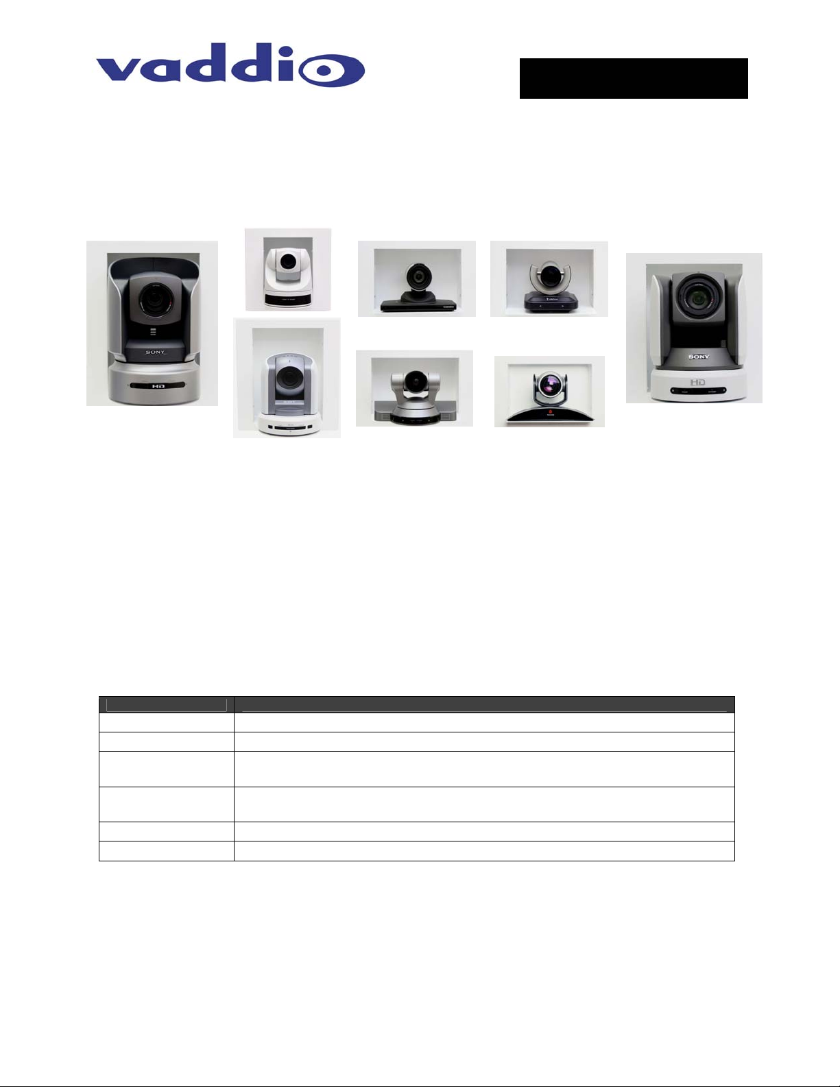
Figure 1: IN-Wall Systems (clockwise, left to right), Sony BRC-H700, EVI-D70, TANDBERG Precision HD, LifeSize, Sony
BRC-Z700, Polycom EagleEye, Sony EVI-HD1 and Sony BRC-300
OVERVIEW:
The Vaddio IN-Wall camera mounting systems are an attractive way to mount PTZ cameras on a wall
where room aesthetics are critical. These mounting systems use the depth of the wall cavity to recess the
camera into the wall, minimizing the camera’s extension into the room and providing a more finished look
to the installation. Cameras from Sony (BRC-H700, BRC-Z700, BRC-300, EVI-D70 and EVI-HD1),
TANDBERG (Precision HD), Polycom (EagleEye and EagleEye 1080 HD) and LifeSize were selected
and the camera enclosures were carefully designed and sized to fit the Vaddio EZCamera Interface
Module (EZIM) in the back of the box to enable use of the Vaddio Quick-Connect CCU and PRO CAT-5
cabling systems for applicable cameras (see below). For the EVI-D70, the Vaddio EZ Camera Shoe can
be attached to the back of the camera. Each system consists of an in-wall mounting box and face frame
which are both powder coated white, but can be painted to match any décor.
IN-Wall Enclosure Supported Cameras and Part Numbers
Part Number Compatible Camera Systems
999-2225-012 Sony EVI-D70 , Vaddio WallVIEW 70 System
999-2225-013 Sony BRC-300, Vaddio WallVIEW CCU or PRO 300 PTZ System
999-2225-014
999-2225-015
999-2225-016 Sony BRC-H700, Vaddio WallVIEW CCU or PRO H700 PTZ System
999-2225-017 Sony BRC-Z700, Vaddio WallVIEW CCU or PRO Z700 PTZ System
UNPACKING:
Carefully remove the product and all of the parts from the packaging and identify the following parts:
• Back Box Enclosure
• Camera Platform
• Face Frame
• Mounting Hardware
• Documentation
(Camera Not Included)
Sony EVI-HD1, Vaddio WallVIEW CCU or PRO HD1 PTZ System,
WallVIEW EagleEye 1080 HD and Polycom EagleEye 1080 HD
Vaddio WallVIEW PRO EagleEye, Polycom EagleEye,
TANDBERG Precision HD and LifeSize
©2008 Vaddio - All Rights Reserved. IN-Wall Enclosures - Document Number 341-744 Rev C
Page 2
IN-Wall Enclosures
Deep Back Box Enclosure
The 3-15/16” deep metal wall box uses the maximum depth of a standard 2” x 4” framed wall cavity, with
½” drywall covering the wall and minimizes the camera’s protrusion into the room. The extra depth
accommodates the Vaddio EZIM for use with Cat. 5 cabling, or the EZ Camera Shoe for the EVI-D70.
Each Enclosure is outfitted with three (3) conduit knockouts (2-sides, 1-top) for flexibility, along with a
cable pass-through in the base of the platform for standard camera cabling.
Before Installing
When locating the IN-Wall enclosure, consider viewing angles, lighting conditions, possible line of site
obstructions and check for in-wall obstructions where the camera is to be mounted. Pick a mounting
location to optimize the performance of the camera. Read the step-by-step instructions fully before
starting the installation.
INSTALLATION INSTRUCTIONS:
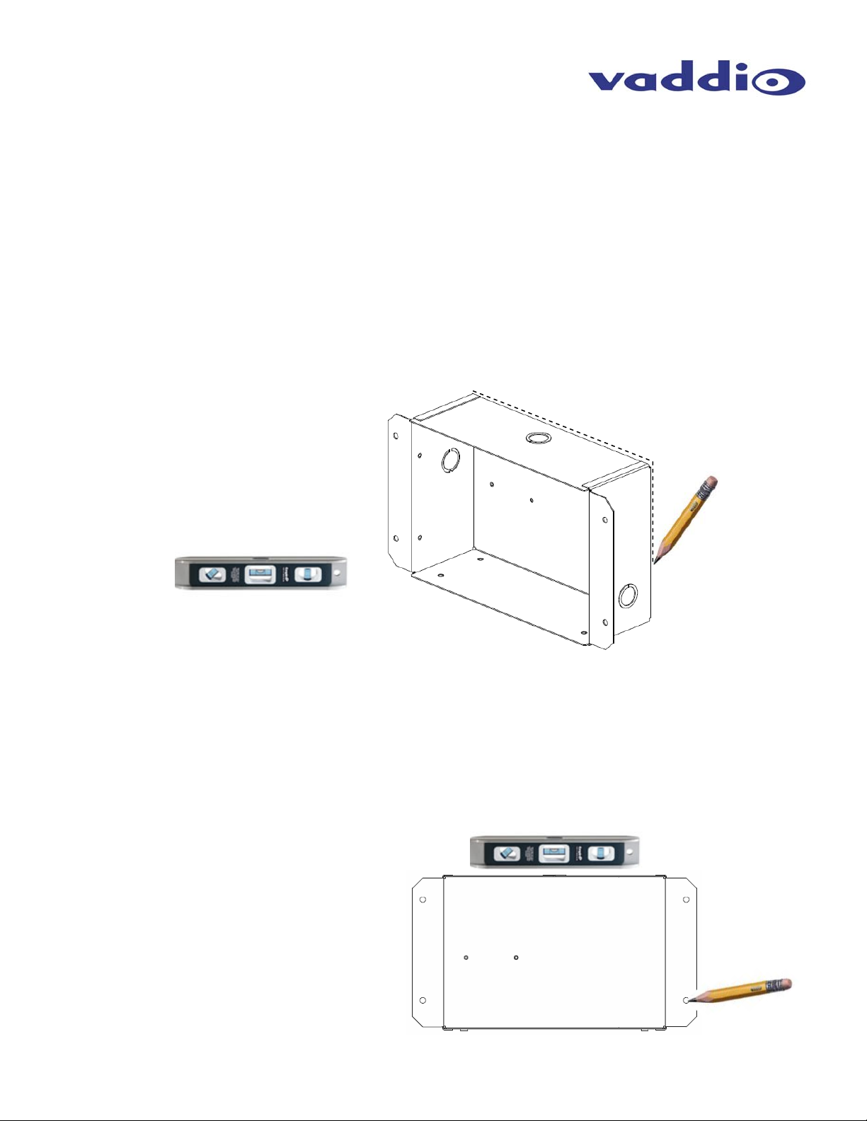
1) Position the back box enclosure against the wall, level the box and trace the outline of the box on the
wall with a pencil.
Figure 2:
Use a level to position the enclosure
and trace a line around the back of
the enclosure once the box is level.
Cut this area out only after verifying
that no studs or obstructions exist
behind the drywall.
2) IMPORTANT: Prior to cutting the drywall, check for studs, conduits or obstructions that could
interfere with the installation. After verification, cut out the area marked on the wall with a drywall saw.
3) Cabling should be routed at this time. Decide which conduit knock-out will be used on the IN-Wall
enclosure and carefully remove it.
4) Place the enclosure into the wall opening for a dry fit and mark the four holes for the spiral wall
anchors through the mounting flanges. The integrator can use any wall anchor of their choice or use
the supplied wall anchors.
Figure 3:
With the box in the opening, mark
the four locations for the wall
anchors.
Remove the box and install the wall
anchors - reinstall the box pulling the
cables through the conduit opening.
Check for a level enclosure and
adjust the opening as needed.
IN-Wall Enclosures - Document 341-744 Rev. C Page 2 of 4
Page 3

IN-Wall Enclosures
INSTALLATION (continued):
5) Remove the box from the wall and install the wall anchors.
6) Pull the cabling through the conduit knock-out and push the back box back into the opening. Be sure
to leave enough slack in the cable to enable termination and the freedom to push the cable back into
the wall cavity when the camera is attached to the platform. Fasten the enclosure to the wall with the
screws supplied into the wall anchors.
7) Next, place the Camera Platform onto the bottom of the Back Box, and screw the platform down with
the four flat head machine screws (Figure 4).
8) The face frame has four screw holes for mounting the frame to the back box. The steps for installing
the face frame are as follows:
a. On the sides of the face frame, there are four holes (Figure 4) for attaching the Face Frame
to the Back Box with the supplied white pan head machine screws.
Face
Frame
Figure 4:
Back of the face frame and front of the IN-Wall box enclosure. The four holes on the face frame match up with the
threaded holes in the enclosure and are screwed into place.
Screw holes for
mounting the
Face Frame to
the Back Box
Camera
Platform
b. If an EZIM is to be installed in the Back Box, connect the break out cable to the EZIM, then
screw the EZIM into place. If you are using standard cabling for the PTZ camera, those
cables can be run through either one of the conduit knock-outs, or the slot at the bottom of
the Back Box. For the EVI-D70, attach the EZ Camera Shoe to the back of the camera.
c. Connect the CAT-5 cables to the EZIM, making sure that the cables are connected to the
appropriate ports. NOTE: Plugging the wrong CAT-5 cable into the wrong port can damage
either the Quick-Connect system or the camera and void the warranty.
d. Next, connect the break out cables to the PTZ camera, and place the camera on the shelf.
Attach the camera to the camera using the appropriate screws supplied with the mount.
IN-Wall Enclosures - Document 341-744 Rev. C Page 3 of 4
Page 4

IN-Wall Enclosures
WARRANTY INFORMATION
Hardware* Warranty - One year limited warranty on all parts. Vaddio warrants this product against defects in
materials and workmanship for a period of one year from the day of purchase from Vaddio. If Vaddio receives notice
of such defects during the warranty period, they will, at their option, repair or replace products that prove to be
defective.
Exclusions - The above warranty shall not apply to defects resulting from: improp er or inadequate maintenance by
the customer, customer applied software or interfacing, unauthorized modifications or misuse, operation outside the
normal environmental specifications for the product, use of the incorrect power supply, improper extension of the
power supply cable or improper site operation and maintenance.
Vaddio Customer service – Vaddio will test, repair, or replace the produc t or products without charge if the unit is
under warranty and is found to be defective. If the product is out of warranty, Vaddio will test then repair the product
or products. The cost of parts and labor charge will be estimated by a technician and co nfirmed by the customer prior
to repair. All components must be returned for testing as a complete unit. Vaddio will not accept res ponsibility for
shipment after it has left the premises.
Vaddio Technical support - Vaddio technicians will determine and discuss with the customer the criteria for repair
costs and/or replacement. Vaddio Technical Support can be contacted through one of the following resources: e-mail
support at support@vaddio.com or online at www.vaddio.com.
Return Material Authorization (RMA) number - Before returning a product for repair or replacement, request an
RMA from Vaddio’s technical support. Provide a technician with a return phone number, e-mail address, shippi ng
address, and product serial numbers and describe the reason for repairs or returns as well as the date of purchase
and proof of purchase. Include your assigned RMA numb er in all corresponde nce with Vaddio. Write your assigned
RMA number on the shipping label of the box when returnin g the product. Please see Vaddio’s website for current
RMA policies and procedures.
Voided warranty – The warranty does not apply if the origin al serial number has been removed or if the prod uct has
been disassembled or damaged through misuse, accident, modifications, or unauthorized repair. Cutting the power
supply cable on the secondary side (low voltage side) to extend the power to the device (camera or cont roller) voids
the warranty for that device.
Shipping and handling - Vaddio will not pay for inbound shipping transportation or insurance charges or accept any
responsibility for laws and ordinances from inbo und transit . Vaddio will pay for outb ound ship ping, transportatio n, and
insurance charges for all items under warranty but will not assume responsibility for loss and/or damage by the
outbound freight carrier. If the return shipment appears damaged, retain the original boxes and packing material for
inspection by the carrier. Contact your carrier immediately.
Products not under warranty - Payment arrangements are required before outbound shipment for all out of
warranty products.
*Vaddio manufactures its hardware products from parts and components that are new or equivalent to new in
accordance with industry standard practices.
Toll Free: 800-572-2011
www.vaddio.com
©2009 Vaddio - All Rights Reserved. Reproduction in whole or in part without written permission is prohibited. Specifications and pricing are
subject to change without notice. Vaddio, IN-Wall, EZCamera, EZIM and WallVIEW are registered trademarks of Vaddio. All other
Wall Enclosures - Document 341-744 Rev. C Page 4 of 4
IN-
trademarks are property of their respective owners. Document Number 341-744 Rev C.
 Loading...