

Page 1
Installation and User Guide
IN-WALL™ RECESSED CAMERA MOUNTING SYSTEMS
Recessed Camera Mounting Systems for Vaddio™, Sony®, Polycom®, LifeSize®, Cisco®
PTZ Cameras and Vaddio™ EZCamera™ Cable System Packages
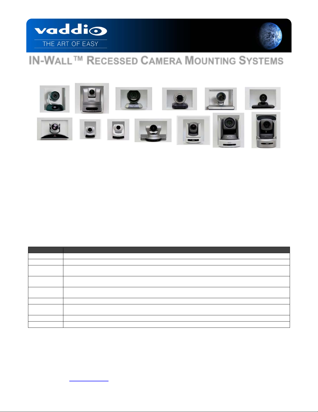
Images: IN-Wall Systems - Top Row (left to right) Vaddio RoboSHOT™ and HD-Series (HD-18/19/20/22/30/USB), LifeSize 10X and
4X, Cisco Precision 60 and PrecisionHD. Bottom Row (left to right): Polycom EagleEye, Sony EVI-D100, EVI-D70, EVI-HD1, BRCZ330, Sony BRC-Z700 and BRC-H700.
OVERVIEW:
The Vaddio IN-Wall camera mounting systems are an attractive way to mount PTZ cameras on a wall where room
aesthetics are critical. These mounting systems use the depth of the wall cavity to minimize the camera’s extension
into the room while providing a finished look to the installation. Cameras from Sony (BRC Series and EVI-D100,
EVI-D70, EVI-HD1 EVI-D80/90 and EVI-H100), Cisco (Precision HD, PrecisionHD 1080p, Precision60), Polycom
(EagleEye, EagleEye 1080 HD an EagleEye IV) and LifeSize (4X and 10X) were selected and the camera
enclosures were carefully designed and sized to fit the Vaddio EZCamera Interface Module (EZIM) in the back of
the box to enable use of the Vaddio Quick-Connect™ CCU and PRO Cat-5 cabling systems for appli cable cameras
(see below). For the EVI-D100, EVI-D70/80/90 and VC-C50i, the Vaddio EZCamera Shoe can be attached to the
back of the camera. Each system consists of an in-wall mounting box, camera platform and face frame, which are
powder coated white, but can be painted to match any décor.
IN-Wall Enclosure Supported Cameras and Part Numbers
Part Number Compatible Camera Systems
999-2225-018 Vaddio ClearVIEW™, WallVIEW™ HD Series or RoboSHOT Series Systems
999-2225-012 Sony EVI-D70 , Vaddio WallVIEW 70 System
999-2225-014
999-2225-015
999-2225-016
999-2225-011 Sony EVI-D100, Vaddio Model & WallVIEW 100 System
999-2225-019
999-2225-020 Cisco Precision 60
999-2225-220 LifeSize 10X PTZ
Intended Use: Please read the entire manual thoroughly. The IN-Wall Enclosure was designed, built and tested
for use indoors and for a particular camera listed above. Mounting the wrong camera in the IN-Wall may create a
potentially unsafe operating condition.
Save These Instructions: The information contained in this manual will help you install and operate your product.
If these instructions are misplaced, Vaddio keeps copies of Specifications, Installation and User Guides and most
pertinent product drawings for the Vaddio product line on the Vaddio website. These documents can be
downloaded from www.vaddio.com free of charge.
Sony EVI-HD1, Vaddio WallVIEW CCU or PRO HD1 PTZ System, WallVIEW EagleEye 1080 HD and Polycom
EagleEye 1080 HD
Polycom EagleEye and EagleEye IV, Vaddio WallVIEW PRO EagleEye, Cisco PrecisionHD, Cisco PrecisionHD 1080p
and LifeSize 4X PTZ
Sony BRC-H700, Vaddio WallVIEW CCU or PRO H700 PTZ System
Sony BRC-Z700, BRC-H900 Vaddio WallVIEW CCU or PRO Z700 PTZ System
Sony BRC-Z330, Vaddio WallVIEW CCU or PRO Z330 PTZ System, EVI-D80 EVI-D90, EVI-H100, Vaddio WallVIEW
80 & 90
©2014 Vaddio - All Rights Reserved. IN-Wall Enclosures - Document Number 341-744 Rev E
Page 2
IN-Wall Enclosures
UNPACKING:
Carefully remove the product and all of the parts from the packaging and identify the following parts:
One (1) Back Box Enclosure
One (1) Camera Platform
One (1) Face Frame
One (1) Set Mounting Hardware and Screws
Four (4) 8-32 X ¼” White Pan Head Screws (for Face Frame attachment)
Note: Cameras are
not included with the
IN-Wall mounts.
Four (4) 10-32 x ¼” Flat Head Screws (for Camera Platform attachment)
Four (4) Self-Drilling Drywall Anchors
Four #8 x 1.25” Screws for Wall Anchors
One (1) ¼” x 20 Camera Mounting Screw (for those cameras that use ¼” x 20 screws)
-OR-
Four (4) M3x6mm Camera Mounting Screws for Polycom EagleEye Cameras (non-Sony)
One (1) Manual
Deep Back Box Enclosure
The 3-15/16” deep metal wall box uses the maximum depth of a standard 2” x 4” framed wall cavity and minimizes
the camera’s protrusion into the room. The extra depth accommod ates the Vaddio EZIM for use with Cat. 5 cabling ,
or the EZCamera Shoe for the EVI-D70/80/90, EVI-D100 and Canon VC-C50i. Each Enclosure is outfitted with
three (3) conduit knockouts (2-sides, 1-top) and a cab le pass-through in the back box and camera platform.
Before Installing
When locating the IN-Wall enclosure, consider viewing angles, lighting conditions, possible line of site obstructions
and check for in-wall obstructions where the camera is to be mounted. Pick a mounting location to optimize the
performance of the camera. Please read the step-by-step instructions fully before starting the installation.
INSTALLATION INSTRUCTIONS:
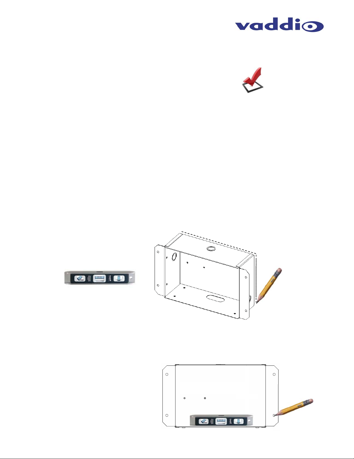
1) Position the back box enclosure against the wall, level the box and trace the outline of the box on the wall with
a pencil.
Drawing:
Use a level to position the enclosure
and trace a line around the back of
the enclosure once the box is level.
Cut this area out only after verifying
that no studs or obstructions exist
behind the drywall.
2) Prior to cutting the drywall, check for studs, conduits or obstructions that could interfere with the installation.
After verification, cut out the area marked on the wall with a drywall saw.
3) Place the enclosure into the wall opening for a dry fit and mark the four holes for the spiral wall anchors through
the mounting flanges. The integrator can use any wall anchor of their choice or use the supplied wall an cho rs.
Figure 3:
With the box in the opening and the box level, mark
the four wall anchor locations.
Remove the box and install the wall anchors reinstall the box pulling the cables through the
conduit opening.
Check for a level enclosure and adjust the opening
as needed.
IN-Wall Enclosures - Document 341-744 Rev E Page 2 of 4
Page 3

IN-Wall Enclosures
4) Remove the Back Box from the wall and install the spiral wall anchors.
5) The in-wall cabling can be routed at this time. Decide which conduit knock-out will be used on the IN-Wall
enclosure and carefully remove it. The floor of the back box and the camera platform also have cable passthrough openings.
6) Pull the cabling through the conduit knock-out or cable pass-through and push the back box back into the
opening. Be sure to leave enough slack in the cable to enable termination and the freedom to push the cable
back into the wall cavity when the camera is attached to the platform. Fasten the en closure t o the wall with the
supplied screws and wall anchors.
7) On the sides of the face frame, there are four holes (see drawing below) for attaching the Face Frame to the
Back Box with the supplied white pan head machine screws.
Four screw holes for
mounting the Face
Frame to the Back Box
Face Frame
attached to
back box
EZIM
Mounting
Nuts X 2
Cable Pass
Through
Face Frame
(rear view)
Drawing:
Back of the face frame and front of the IN-Wall box enclosure shown. The four holes on the face frame match up with
the threaded holes in the enclosure.
Camera
Platform
8) Place the Camera Platform onto the bottom of the Back Box, and screw the platform down with the four flat
head machine screws. If using the cable pass-through, thread the cables through the cable slot on the came ra
platform before screwing down the platform.
9) If an EZIM is to be installed in the Back Box, connect the break out cable to the EZIM and screw the EZIM into
place. If you are using standard cabling for the PTZ camera, those cables can be run through either one of the
conduit knock-outs, or the slot at the bottom of the Back Box. For the EVI-D70, EVI-D100 and Canon VC-C50i,
attach the EZ Camera Shoe to the back of the camera.
a. Connect the Cat-5 cables to the EZIM, making sure that the cables are connected to the appropriate ports.
NOTE: Plugging the wrong Cat-5 cable into the wrong port can damage either the Quick-Connect system
or the camera and void the warranty, which is bad, generally.
b. Connect the break out cables to the PTZ camera, and place the camera on the shelf.
10) Attach the camera to the camera using the appropriate screws supplied with the mount.
IN-Wall Enclosures - Document 341-744 Rev E Page 3 of 4
Page 4

IN-Wall Enclosures
p
Warranty Information
(See Vaddio Warranty, Service and Return Policies posted on vaddio.com for complete details):
Hardware* Warranty: Two (2) year limited warranty on all parts and labor for Vaddio manufactured products. Vaddio warrants
its manufactured products against defects in materials and workmanship for a period of two years from the day of purchase, to
the original purchaser, if Vaddio receives notice of such defects during the warranty period. Vaddio, at its option, will repair or
replace products that prove to be defective. Vaddio manufactures its hardware prod ucts from parts and components that are
new or equivalent to new in accordance with industry standard practices.
Exclusions: The above warranty shall not apply to defects resulting from improper or inadequate maintenance by the customer,
customers applied software or interfacing, unauthorized modifications or misuse, mishandling, operation outside the normal
environmental specifications for the product, use of the incorrect, modified or extended power supply or improper site operation
and maintenance. Please note that OEM products and pr oducts manufactured by other companies are excluded from the
Vaddio warranty and are covered by the original manufacturer’s warranty.
Vaddio Customer Service: Vaddio will test, repair, or replace the product or products without charge if the unit is under
warranty. If the product is out of warranty, Vaddio will test, then repair the product or products. The parts and labor charge will
be estimated by a technician and confirmed by the customer prior to repair. All components must be returne d for testing as a
complete unit. Vaddio will not accept responsibility for shipment after it has left the premises.
Vaddio Technical Support: Vaddio technicians will determine and discuss with the customer the criteria for repair costs and/or
replacement. Vaddio Technical Support can be contacted through one of the following resources: e-mail support at
support@vaddio.com or online at www.vaddio.com.
Return Material Authorization (RMA) Number: Before returning a product for repair or replacem ent, request an RMA from
Vaddio’s technical support. Provide tech support with a return phone number, e-mail address, shipping address, product serial
numbers and original purchase order number. Describe the reas on for repairs or returns as well as the date of purchas e. See
the General RMA Terms and Procedures section for more information. RMA’s are valid for 30 days and will be issued to Vaddio
dealers only. End users must return products through Vaddio dealers. Include the assigned RMA number in all correspondence
with Vaddio. Write the assigned RMA number clearly on the s hipping label of the box (not on the box) when returning the
product. All products returned for credit are subject to a restocking charge without exception.
Voided Warranty: The warranty does not apply if the original ser ial number has been removed or if the product has been
disassembled or damaged through misuse, accident, modifications, use of incorrect, modified or extended po wer supply, or
unauthorized repair.
Shipping and Handling: Vaddio will not pay for inbound shipping transportation or insurance charges or accept any
responsibility for laws and ordinances from inbound transit. Vaddio will pay for outbound shipping, transportation, and insurance
charges for all items under warranty but will not assume responsibility for loss and/or damage by the outbound freight carrier. If
the return shipment appears damaged, retain the original boxes and packing material for inspection by the carrier. Contact your
carrier immediately.
Products not under Warranty: Payment arrangements are required before outbound shipment for all out of warranty products.
Other General Information:
Care and Cleaning
Do not attempt to take this product apart at any time. There are no user-serviceable components inside.
Do not spill liquids in the product
Keep this device away from food and liquid
For smears or smudges on the product, wipe with a clean, soft cloth
Do not use any abrasive chemicals.
Operating and Storage Conditions:
Do not store or operate the device under the following conditions:
Temperatures above 40°C (104°F) or temperatures below 0°C (32°F)
High humidity, condensing or wet environments
In inclement weather
Dry environments with an excess of static discharge
In orbit (space junk issue)
Under severe vibration
©2014 Vaddio - All Rights Reserved. Reproduction in whole or in part without written permission is prohibited. Specifications and pricing are subject to change without notice or
IN-Wall Enclosures - Document 341-744 Rev E Page 4 of 4
obligation. Vaddio, IN-Wall, RoboSHOT, Quick-Connect, EZCamera, EZIM, ClearVIEW and WallVIEW are trademarks of Vaddio. All other trademarks are property of the ir
res
ective owners. Planet HD-189733b in front page header courtesy of Hubble Space Telescope. SD: 68163.8. Document Number 341-744 Rev E,
 Loading...