


 Loading...
page 1 of 49
Technology for Vacuum Systems
Instructions for use
PC 2001 VARIO
Chemistry pumping units with speed control
Documents are only to be used and distributed completely and unchanged. It is strictly the users´ responsibility to check carefully the validity of this document with respect to his product. manual-no.: 999100 / 06/05/2008
page 2 of 49
Dear customer,
Your VACUUBRAND diaphragm pump shall support you at your work for a long time without any trouble and with full load output.Thanks to our large practical experience we attained much information how you could add to an efficient application and to personal safety. Please read these instructions for use prior to the initial start-up of your pump.
VACUUBRAND diaphragm pumps are the result of many years of experience in construction and practical operation of these pumps combined with the latest results in material and manufacturing technology.
Our quality maxim is the ”zero fault principle”:
Every delivered diaphragm pump is tested extensively including an endurance run of 18 hours. Due to this endurance run, also faults, which occur rarely, are reported an can be corrected. Every single diaphragm pump is tested on achievement of the specification after the endurance run.
Every VACUUBRAND pump leaving our factory achieves the specification.We feel obliged to this high quality standard.
We are aware that the vacuum pump should not draw a part of the real work and we hope to contribute with our products to an effective and troublefree realisation of your work.
Yours
VACUUBRAND GMBH + CO KG
After sales service: Contact your local dealer or call +49 9342 808-193.
Documents are only to be used and distributed completely and unchanged. It is strictly the users´ responsibility to check carefully the validity of this document with respect to his product. manual-no.: 999100 / 06/05/2008

page 3 of 49 |
|
Contents |
|
Safety information! .................................................................................................... |
4 |
Technical data............................................................................................................ |
7 |
Description .............................................................................................................. |
10 |
Use and operation ................................................................................................... |
12 |
General view modes ................................................................................................ |
16 |
How to configurate the controller .......................................................................... |
17 |
General view mode vacuum control ...................................................................... |
20 |
Mode vacuum control ............................................................................................. |
21 |
Mode continuous pumping .................................................................................... |
25 |
General view mode VACUU•LAN............................................................................ |
27 |
Mode VACUU•LAN .................................................................................................. |
28 |
Accessories ............................................................................................................. |
30 |
Troubleshooting ...................................................................................................... |
31 |
Readjustment .......................................................................................................... |
33 |
How to determine the best distillation conditions ................................................ |
34 |
Interface parameters ............................................................................................... |
35 |
Read commands ..................................................................................................... |
36 |
Write commands...................................................................................................... |
37 |
Replacing diaphragms and valves ........................................................................ |
38 |
Cleaning and assembling components ................................................................. |
44 |
Calibration in the factory......................................................................................... |
45 |
Notes on return to the factory ................................................................................ |
46 |
Health and safety clearance form .......................................................................... |
47 |
Attention! Important notes! |
|
Not permitted! Misuse may cause damage.
Caution! Hot surface!
Isolate equipment from mains.
Note.
Documents are only to be used and distributed completely and unchanged. It is strictly the users´ responsibility to check carefully the validity of this document with respect to his product. manual-no.: 999100 / 06/05/2008

page 4 of 49
Safety information!
Remove all packing material, remove the product from its packing-box, remove the protective covers from the inlet and outlet ports and keep, inspect the equipment.
If the equipment is damaged, notify the supplier and the carrier in writing within three days; state the item number of the product together with the order number and the supplier’s invoice number. Retain all packing material for inspection.
Do not use the equipment if it is damaged.
If the equipment is not used immediately, replace the protective covers. Store the equipment in suitable conditions.
Read and comply with this manual before installing or operating the equipment.
Transport the pump at the provided handle.
Use the equipment for the intended use only (for generation and measurement of vacuum).
Prevent any part of the human body from coming in contact with vacuum.
Comply with notes on correct vacuum and electrical connections, see section ”Use and operation”.
Make sure that the individual components are only connected, combined and operated according to their design and as indicated in the instructions for use.
Comply with national safety regulations and safety requirements concerning the use of vacuum and electrical equipment.
The mains switch for the controller and the pump is at the rear side of the controller.
After switching off the pump, wait 60 sec. minimum until next switching on.
Equipment must be connected only to a suitable fused and protected electrical supply and a suitable earth point. Failure to connect the pumping unit to ground may result in deadly electrical shock.
The supply cable may be fitted with a moulded European IEC plug or a plug suitable for your local electrical supply. If the plug has been removed or has to be removed, the cable will contain wires colour coded as follows: green or green and yellow: earth; blue or white: neutral; brown or black: live.
Check that mains voltage and current conform with the equipment (see rating plate).
If the equipment is brought from cold environment into a room for operation, allow the equipment to warm up (pay attention to water condensation on cold surfaces).
Make sure ventilation is adequate if pump is installed in a housing or if ambient temperature is elevated.
Comply with all relevant safety requirements (regulations and guidelines) and adopt suitable safety measures.
Provide a firm level platform for the equipment and check that the system to be evacuated is mechanically stable and that all fittings are secure.
Attention: Flexible elements tend to shrink when evacuated.
Due to the high compression ratio of the pumps, pressure at the outlet port might be generated being higher than the max. permitted pressure compatible with the mechanical stability of the system.
Comply with maximum permitted pressures and pressure differences, see section ”Technical data”. Do not operate the pump with overpressure at the inlet.
Do not permit any uncontrolled pressurizing (e. g. make sure that the exhaust pipeline cannot become blocked). If you have an exhaust-isolation valve, make sure that you cannot operate the equipment with the valve closed. Risk of bursting!
Ensure that the system design does not allow the exhaust pipeline to become blocked.
Max. permitted pressure at the pressure transducer: 1.5 bar (absolute).
Documents are only to be used and distributed completely and unchanged. It is strictly the users´ responsibility to check carefully the validity of this document with respect to his product. manual-no.: 999100 / 06/05/2008

page 5 of 49
Ensure that the system design does not allow the coolant outlet pipeline to become blocked.
Secure coolant hoses at the hose nozzles (e.g. with hose clip) to prevent their accidental slipping.
Check liquid level in both catchpots regularly and drain condensate in time.
Check the overpressure safety relief device at the exhaust waste vapour condenser in appropriate intervals.
Avoid overpressure of more than 0.2 bar in case inert gas is connected.
The diameter of the inlet and outlet pipeline should be at the least as large as the diameter of the pump connection pipelines.
To the best of our knowledge the equipment is in compliance with the requirements of the applicable EC-directives and harmonized standards (see “Declaration of conformity”) with regard to design, type and model, especially directive IEC 1010.This directive gives in detail conditions, under which the equipment can be operated safely (see also IP degree of protection).
Adopt suitable measures in case of differences, e. g. using the equipment outdoors, installation in altitudes of more than 1000 m above mean sea level, conductive pollution or dewiness.
Pay attention to symbol “hot surfaces“ on the equipment (according to IEC 1010 recommendation).
Adopt suitable measures to prevent any danger arising from the formation of hot surfaces or electric sparks.
The pumps have no approval for operation in or for pumping of potentially explosive atmospheres.
If pumping different substances, purge the pump with inert gas prior to changing the pumped media in order to pump out residues and to avoid reactions of the pumped substances with each other with and the pump material.
Take into consideration interactions and chemical reactions of the pumped media.
The pumps are not suitable for pumping substances which may form deposits inside the pump.
If there is a danger of the formation of deposits in the pump chamber (check inlet and outlet of the pump) inspect the pump chamber regularly and clean if necessary.
The pumps are not suitable to pump unstable substances and substances which react explosively under impact (mechanical stress) and/or when being exposed to elevated temperatures without air.
The pumps are not suitable to pump self inflammable substances, substances which are inflammable without air and explosive substances.
The pumps are not suitable for pumping dust and have no approval for operation below ground.
Ensure that the materials of the wetted parts are compatible with the pumped substances, see section “Technical data”.
Adopt suitable measures to prevent the release of dangerous, explosive, corrosive or polluting fluids.
Use inert gas for gas ballast if necessary.
The user must take suitable precautions to prevent any formation of explosive mixtures in the pump. In case of a diaphragm crack, mechanically generated sparks, hot surfaces or static electricity may ignite these mixtures.
Take adequate precautions to protect people from the effects of dangerous substances, wear appropriate safety-clothing.
Comply with applicable regulations when disposing of chemicals.Take into consideration that chemicals may be polluted.
The motor is protected by a temperature sensor at the circuit board: Current limitation if the temperature at the circuit board is higher than 70°C, switching off the pump if the temperature is higher than 85°C.
Documents are only to be used and distributed completely and unchanged. It is strictly the users´ responsibility to check carefully the validity of this document with respect to his product. manual-no.: 999100 / 06/05/2008

page 6 of 49
In case of blockade of the motor (after 10 attempts to start-up) the pump is switched off.
If the pump is switched off due to safety measures, manual reset is necessary. Isolate the pump from mains. Eliminate cause of failure before restarting the pump.
Avoid high heat supply (e. g. due to hot process gases).
Ensure sufficient air admittance if pump is installed in a housing.
Due to the residual leak rate of the equipment, there may be an exchange of gas, albeit extremely slight, between the environment and the vacuum system.
Adopt suitable measures to prevent contamination of the pumped substances or the environment.
Pumping at high inlet pressure may lead to overpressure at the gas ballast valve.
Pumped gases or condensate might be pushed out if the valve is open.
If an inert gas supply is connected, ensure that the inlet pipeline is not contaminated.
The controller is equipped with a short circuit proof transformer with an integrated overload protection (no fuses).
Failure of the pump (e. g. by power failure) or connected components, parts of the supply (e. g. coolant) or change of parameters (e. g. increase of pressure in the coolant system) must not lead to a critical dangerous situation under any circumstances.
Electronic equipment is never 100% fail-safe. This may lead to an indefinite status of the equipment. Provide protective measures against misfunction and failure.
Operating the pump with high or low frequency, stand still of the pump or operating the venting valve must not lead to a critical dangerous situation under any circumstances.
Ensure that in case of failure the pump and the vacuum system always will turn into a safe status.
In case of diaphragm cracks or leaks in the manifold pumped substances might be released into the environment or into the pump housing.To reduce the risk of leaks, ask for a diaphragm pump with additional safety diaphragm.
Comply especially with notes on operation and use and maintenance.
Use only genuine spare parts and accessories.
Otherwise safety and performance of the equipment as well as the electromagnetic compatibility of the equipment might be reduced.
Possibly the CE mark or the C/US conformity becomes invalid if not using genuine spare parts.
Ensure that maintenance is done only by suitably trained and supervised technicians. Ensure that the maintenance technician is familiar with the safety procedures which relate to the product processed by the vacuum system and that the equipment, if necessary, is appropriately decontaminated before starting maintenance.
Comply with local and national safety regulations.
Wear parts have to be replaced regularly. In case of normal wear the lifetime of the diaphragms and valves is > 10000 operating hours. Bearings have a typical durability of 40000 h.
Before starting maintenance vent the system, isolate the pump and other components from the vacuum system and the electrical supply, drain condensate and allow sufficient cooling of the pump.
Before starting maintenance, wait two minutes after isolating the equipment from mains to allow the capacitors to discharge.
Never operate the pump if covers or other parts of the pump are disassembled. Never operate a defective or damaged pump.
Repair of the gauge head VSK 5 is not possible.
In order to comply with law (occupational, health and safety regulations, safety at work law and regulations for environmental protection) vacuum pumps, components and measuring instruments returned to the manufacturer can be repaired only when certain procedures (see section “Notes on return to the factory“) are followed.
Documents are only to be used and distributed completely and unchanged. It is strictly the users´ responsibility to check carefully the validity of this document with respect to his product. manual-no.: 999100 / 06/05/2008
page 7 of 49
Technical data
Type |
|
PC 2001 VARIO |
|
|
|
|
|
Maximum pumping speed |
m3/h |
1.7 |
|
(according to ISO 21360) |
|||
|
|
||
|
|
|
|
Ultimate (total) vacuum (absolute) at |
mbar |
2 |
|
'continuous pumping HI' |
|||
|
|
||
|
|
|
|
Ultimate (total) vacuum (absolute) with |
mbar |
4 |
|
gas ballast at 'continuous pumping HI' |
|||
|
|
||
|
|
|
|
Max. permitted pressure at the outlet |
bar |
1.1 |
|
(absolute) |
|||
|
|
||
|
|
|
|
Max. permitted pressure at the gas |
bar |
1.2 |
|
ballast (absolute) |
|||
|
|
||
|
|
|
|
Permitted ambient temperature at |
|
|
|
storage |
°C |
-10 to +60 |
|
operation |
°C |
+10 to +40 |
|
|
|
|
|
Permitted relative atmospheric moisture |
% |
30 to 85 |
|
during operation (no condensation) |
|
|
|
|
|
|
|
No-load speed* |
min-1 |
0 - 2200 |
|
|
|
|
|
Rated current |
|
|
|
100 V~ |
A |
1.6 |
|
230 V~ |
A |
0.7 |
|
|
|
|
|
Power draw |
kW |
0.16 |
|
|
|
|
|
Max. permitted range of voltage supply |
|
100-120 V~ +5/-10% 50/60 Hz |
|
(see rating plate!) |
|
230 V~ +/-10% 50/60 Hz |
|
|
|
|
|
Motor protection |
|
temperature sensor on the pcb (current |
|
|
|
limitation) |
|
|
|
|
|
Degree of protection |
|
IP 20 |
|
|
|
|
|
Inlet |
|
hose nozzle NW 6/10 |
|
|
|
|
|
Outlet |
|
hose nozzle NW 10 |
|
|
|
|
|
Dimensions L x W x H approx. |
mm |
316 x 295 x 472 |
|
|
|
|
|
Weight approx. |
kg |
10.1 |
|
|
|
|
*Note:
In the motor speed range between 0 and 350 rpm the pump is running automatically in a clocked interval operation.
Gas inlet temperatures:
Operating condition |
Inlet pressure |
Permitted range of gas |
|
temperatures at inlet |
|||
|
|
||
Continuous operation |
> 100 mbar (high gas load) |
+10°C to +40°C |
|
|
|
|
|
Continuous operation |
< 100 mbar (low gas load) |
0°C to +60°C |
|
|
|
|
|
Short-time operation (< 5 minutes) |
< 100 mbar (low gas load) |
-10°C to +80°C |
|
|
|
|
We reserve the right for technical modifications without prior note!
Documents are only to be used and distributed completely and unchanged. It is strictly the users´ responsibility to check carefully the validity of this document with respect to his product. manual-no.: 999100 / 06/05/2008
page 8 of 49
Controller |
CVC 2000II |
Pressure transducer |
external, capacitive absolute pressure |
|
transducer made of aluminiumoxide ceramic |
|
|
Pressure units / scale (to be switched between) |
mbar, Torr or hPa |
|
|
Measurement range |
1 mbar - 1100 mbar (1 Torr - 825 Torr) |
|
|
Max. pressure control range* |
1 mbar - 1060 mbar (1 Torr - 795 Torr) |
|
|
Operation frequency range of the motor |
1.0 - 60.0 Hz at steps of 0.5 Hz |
|
and additional "HI" (max.75 Hz) |
|
|
Uncertainty (with transducer carefully |
<+/-1 mbar (1 Torr) +/-1 digit |
calibrated and at constant temperature) |
|
|
|
Temperature coefficient |
<+/- 0.07 mbar/K (0.05 Torr/K) |
|
|
Degree of protection pressure transducer |
IP 54 |
according to IEC 529 |
|
|
|
Max. permitted pressure at the pressure |
1.5 bar (1125 Torr) |
transducer (absolute) |
|
|
|
Max. permitted temperature of gaseous media |
for short periods up to 80°C |
|
|
Serial interface |
RS 232 C |
|
|
*The actual vacuum control range in your special application might be reduced due to ultimate vacuum of the pump, quantity of gas occurring etc.
Components |
Wetted parts |
|
Pumping unit |
|
|
Outlet |
PET |
|
|
|
|
Inlet |
PPS |
|
|
|
|
Hose |
PTFE |
|
|
|
|
Fitting |
ETFE |
|
O-rings at the catchpot |
FPM |
|
Overpressure safety relief device |
silicone rubber |
|
Catchpot cover plate |
PP |
|
Connection to pressure transducer |
PP |
|
|
|
|
Exhaust waste vapour condenser, collecting |
borosilicate glass |
|
flask |
||
|
||
Pump |
|
|
Housing cover insert |
PTFE |
|
Head cover |
ETFE |
|
Diaphragm clamping disc |
ETFE / carbon |
|
Valve |
FFKM |
|
|
|
|
Diaphragm |
PTFE |
|
|
|
|
VSK 5 |
|
|
Seal |
chemically resistant fluoroelastomer |
|
|
|
|
Pressure transducer housing |
PTFE duroplastic reinforced on stainless steel |
|
|
|
|
Pressure transducer |
Aluminiumoxide ceramic |
|
|
|
We reserve the right for technical modifications without prior note!
Documents are only to be used and distributed completely and unchanged. It is strictly the users´ responsibility to check carefully the validity of this document with respect to his product. manual-no.: 999100 / 06/05/2008

page 9 of 49
PC 2001 VARIO
|
coolant outlet |
|
|
(hose nozzle 6 mm) |
|
|
outlet |
|
|
(gas!; hose nozzle 10 mm) |
|
|
coolant inlet |
|
exhaust waste vapour |
(hose nozzle 6 mm) |
|
|
||
condenser with cover |
handle |
|
|
||
pressure transducer VSK 5 |
gas ballast |
|
overpressure safety |
|
|
relief device at the |
|
|
exhaust waste |
pump MD 1C VARIO |
|
vapour condenser |
||
|
||
inlet (vacuum |
|
|
connection) |
|
|
round bottom flask to |
|
|
collect condensate |
|
|
|
controller CVC 2000II |
Documents are only to be used and distributed completely and unchanged. It is strictly the users´ responsibility to check carefully the validity of this document with respect to his product. manual-no.: 999100 / 06/05/2008
page 10 of 49
Description
The controller can be adapted to the specific application by choosing another mode than ”Vacuum control” (factory-set), see section ”General view modes”.
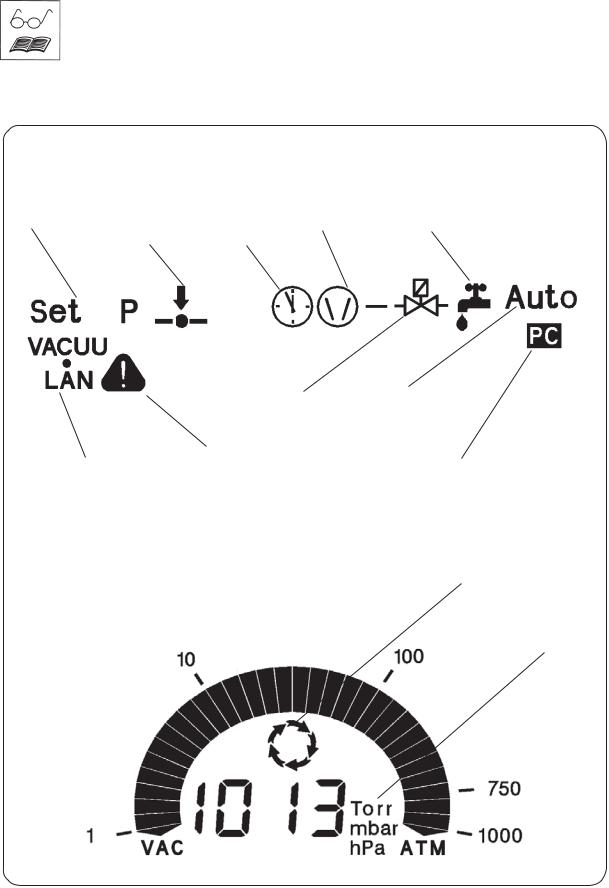
The status of the controller respectively of the connected accessories is displayed by corresponding symbols on the LCD. After switching on the version of the software is displayed, than the mode as well as the symbols “coolant valve” and “venting valve”, if the valves are preselected.
General view display
modes mode vacuum control or |
time |
pump symbol |
coolant valve |
continuous pumping |
counter |
|
|
|
venting valve |
automatic mode |
mode VACUU•LAN |
warning (in combination with |
|
other symbols) |
remote operation |
process control
active
Pressure reading
selectable pressure units
Documents are only to be used and distributed completely and unchanged. It is strictly the users´ responsibility to check carefully the validity of this document with respect to his product. manual-no.: 999100 / 06/05/2008

page 11 of 49
Keys
• setting of frequency |
operating venting valve (only if |
• setting time for switch-off (only VACUU•LAN) |
valve is connected and prese- |
• switching (toggling) in modes |
lected) |
MODE
p
•pressure setting (only vacuum control)
•adapting process pressure
START VENT STOP
CVC 2000II
start or stop of process control or confirmation of selected values or mode
•switch on/off automatic mode (only vacuum control)
•special function (in combination with another key)
Rear side
CVC 2000II
connection pump supply
mains switch 
connection mains cable
female connector to connect pump electronics
female connector
to connect the gauge head VSK 5
 serial interface
RS 232 C
female connector to connect a coolant valve and/or an venting valve
Documents are only to be used and distributed completely and unchanged. It is strictly the users´ responsibility to check carefully the validity of this document with respect to his product. manual-no.: 999100 / 06/05/2008

page 12 of 49
Use and operation
Installing in a vacuum system:
Avoid throttling losses by using connecting pipes with large diameter and keep them as short as possible.
Reduce the transmission of vibration and prevent loading due to rigid pipelines. Insert elastic hoses or flexible elements as couplings between the pump and rigid pipes. Attention: Flexible elements tend to shrink when evacuated.
Use a suitable valve to isolate the pump from the vacuum system to allow the pump to warm up before condensable vapours are pumped or to clean the pump before it is switched off.
Connect the exhaust to a suitable treatment plant to prevent the discharge of dangerous gases and vapours to the surrounding atmosphere. Use a catchpot to prevent the drainage of contaminated condensate back into the pump.
Prior to use:
Max. ambient temperature: 40 °C
Make sure ventilation is adequate if pump is installed in a housing or if ambient temperature is elevated.
If pump is installed in altitudes of more than 1000 m above mean sea level check compatibility with applicable safety requirements, e. g. IEC 60034 (motor may overheat due to insufficient cooling).
When assembling, ensure vacuum-tightness. After assembly, check the complete system for leaks.
Separator at the inlet and exhaust waste vapour condenser at the outlet:
overpressure |
Round bottom flasks: |
|
The catchpot at the inlet prevents droplets and particles from |
||
safety relief |
||
entering the pump. |
||
device |
||
Lifetimes of diaphragms and valves are enhanced. |
||
|
||
flask at the |
Improves vacuum in case of condensation. |
|
outlet |
Both round bottom flasks are coated with a protective layer to |
|
|
prevent disintegration in case of breakage or implosion. |
|
flask at the |
Assemble the catchpots at the inlet and at the outlet using |
|
inlet |
joint clips. |
|
|
|
outlet |
Exhaust waste vapour condenser: |
|
(gas!; hose nozzle 10 mm) |
Assemble hose nozzles for coolant inlet and coolant outlet |
|
|
pipelines at the exhaust waste vapour condenser. |
|
coolant outlet |
The exhaust waste vapour condenser enables an efficient |
|
condensation of the pumped vapours at the outlet. |
||
(hose nozzle 6 mm) |
||
No backflow of condensates. |
||
|
||
coolant inlet |
Controlled recovery of condensates. |
|
Next to 100% solvent recovery. |
||
(hose nozzle 6 mm) |
||
|
The isolation cover protects against glass splinters in case of breaking, acts as thermal isolation to avoid condensation of humidity and is intended to absorb shocks.
Attach the pipelines of the coolant circuit to the respective hose nozzles (see image) at the waste vapour condenser. Check hose connections prior to starting operation of the cooling system.
Secure coolant hoses at the hose nozzles (e.g. with hose clip) to prevent their accidental slipping.
Attention: Install hoses of the cooling system in a way to avoid flow / dropping of condensed water to the pumping unit (especially cables and electronic parts).
Ensure that the coolant outlet pipeline is always free and that it cannot get blocked.
Documents are only to be used and distributed completely and unchanged. It is strictly the users´ responsibility to check carefully the validity of this document with respect to his product. manual-no.: 999100 / 06/05/2008

page 13 of 49
The gas outlet (hose nozzle 10 mm) must not be blocked.The exhaust pipeline has always to be free and pressureless to enable an unhindered discharge of gases.
Connect the exhaust to a suitable treatment plant to prevent the discharge of dangerous gases and vapours to the surrounding atmosphere.
Notes regarding the assembling of the pressure transducer VSK 5
The cable of the gauge head is connected to the female conconnector nector at the rear side of the vacuum controller.
for VSK 5 The gauge head is connected to the vacuum system with a union nut using an adapter.
The device is adjusted together with the gauge head at the factory. If the gauge head is replaced a readjustment is recommended.
|
Max. permitted pressure at the pressure transducer: 1.5 bar (ab- |
|
|
solute). |
|
|
The display flashes at a pressure higher than 1100 mbar. |
|
|
Comply with max. permitted pressure. |
|
pressure |
Inside a vacuum system where evaporation occurs, e. g. |
|
rotary evaporator, the vacuum is not uniform, e. g. a con- |
||
transducer |
||
denser acts as pump or the vacuum in the pipeline is lower |
||
VSK 5 |
||
than in the system.Therefore carefully choose position where |
||
|
||
|
to connect the gauge head. |
|
|
|
The pressure transducer can be disassembled from the inlet of the pumping unit and, after having unscrewed the adapter, assembled using a small flange connection or a hose nozzle (included in delivery) directly to the apparatus.
Close the connection at the inlet of the pumping unit using a blind cap (cat. no.: 67 71 50).
Condensate and deposits in the pressure transducer affect the measuring result.
In case of deposits, aggressive or condensable media, install a gas washing bottle before the pressure transducer if necessary.
In order to avoid malfunction it is important to position the pressure transducer in the vacuum line so as to avoid flow of condensate towards the pressure transducer.
Clean pressure transducer if necessary, see section “maintenance“.
|
Hose nozzle (inlet of the pumping unit): |
|
Alternatively the hose nozzle or a second hose nozzle (in- |
|
cluded in delivery) can be assembled at position 1 or 2 at |
2 |
the inlet of the pumping unit. |
|
Change closing screw and hose nozzle. Ensure that the O- |
|
ring is correctly positioned. |
1
Documents are only to be used and distributed completely and unchanged. It is strictly the users´ responsibility to check carefully the validity of this document with respect to his product. manual-no.: 999100 / 06/05/2008
Before operation

page 14 of 49
During operation:
Do not start or operate the pump if pressure at the outlet is higher than 1.1 bar absolute. Attempts to start or operate the pump at higher pressure may cause blockade and damage of the motor.
Comply with max. permitted pressure at the outlet and max. permitted pressure difference between inlet and outlet.
The pump achieves its pumping speed, ultimate total vacuum and vapour pumping rate only at operating temperature (after approx. 15 minutes).
Prevent internal condensation, transfer of liquids or dust.The diaphragm and valves will be damaged, if liquids are pumped in significant amounts.
Operate the pump with gas ballast valve open to reduce the condensation of pumped media (water vapour, solvents, ....) inside the pump.
The motor is protected by a temperature sensor at the circuit board: Current limitation if the temperature at the circuit board is higher than 70°C, switching off the pump if the temperature is higher than 85°C. In case of blockade of the motor (after 10 attempts to start-up) the pump is switched off.
If the pump is switched off due to safety measures, manual reset is necessary. Isolate the pump from mains. Eliminate cause of failure before restarting the pump.
Avoid high heat supply (e. g. due to hot process gases).
Ensure sufficient air admittance if pump is installed in a housing.
Settings at the controller
Setting of interface parameters, see section “Interface“.
Preselections at the controller, see section “Modes“.
Use and operation of the controller see section “How to operate the controller”.
How to change the pressure units
mbar
+ Torr
Torr
p |
hPa |
Press key p or p during switching on.
The pressure units are displayed, the pressure unit as from last operation is flashing.
Press key p or p to change pressure unit. Press key stop when controller displays the desired pressure unit to finish the operation mode.
Attention: Important notes regarding the use of gas ballast
Make sure that air/gas inlet through the gas ballast valve never leads to hazardous, explosive or otherwise dangerous mixtures. If in doubt, use inert gas.
When using air rather than inert gas, risk of significant damage to equipment and/or facilities, risk of personal injury or even loss of life exists due to the formation of hazardous and/or explosive mixtures if air and pumped media react inside or at the outlet of the pump.
For condensable vapours (water vapour, solvents, ...):
Do not pump vapour before pump has reached its operating temperature and not with gas ballast valve closed.
Open gas ballast valve. Close gas ballast valve by turning 180°.
The gas ballast valve is open if the arrow on the gas ballast cap points towards the pump.
gas ballast |
With gas ballast valve open ultimate vacuum will be reduced, |
|
pumping speed is decreased. |
Use inert gas at the air inlet to avoid the formation of explosive mixtures.
Documents are only to be used and distributed completely and unchanged. It is strictly the users´ responsibility to check carefully the validity of this document with respect to his product. manual-no.: 999100 / 06/05/2008

page 15 of 49
In case of low boiling solvents when the formation of condensate is unlikely, the use of gas ballast might be unnecessary.
Operating the pump without gas ballast increases the solvent recovery rates at the exhaust waste vapour condenser.
Attention: Notes concerning the operation of the exhaust waste vapour condenser
Check hose connections prior to starting operation of the cooling system.
Check coolant hoses regularly during operation.
Ensure that the coolant outlet pipeline is always free and that it cannot get blocked.
Maximum permissible coolant pressure at the exhaust waste vapour condenser: 6 bar (absolute)
Comply with the maximum permissible coolant pressures of additional components in the coolant circuit (e.g coolant valve).
Avoid overpressure in the coolant circuit (e.g. caused by blocked or squeezed coolant hoses).
Permissible range of coolant temperature at the exhaust waste vapour condenser: -15°C to +20°C
The gas outlet (hose nozzle 10 mm) must not be blocked.The exhaust pipeline has always to be free and pressureless to enable an unhindered discharge of gases.
Connect the exhaust to a suitable treatment plant to prevent the discharge of dangerous gases and vapours to the surrounding atmosphere.
In case of condensation:
Check liquid level in both catchpots during operation.Avoid overflowing of the catchpots.Do not overfill the catchpots. Maximum liquid level approx. 80%, to avoid problems
when removing the catchpots.
Check liquid level in both catchpots regularly and drain catchpots in time.
Removing the catchpots: Catchpot at outlet:
Remove joint clip, remove catchpot and drain condensate.
Catchpot at inlet:
Admit air or inert gas (via inlet of pumping unit) to atmospheric pressure. Remove joint clip, remove catchpot and drain condensate.
Reassemble drained catchpots.
Important: Comply with regulations when disposing solvents/condensates. Reuse if possible, purify if contaminated.
Shutdown:
Short-term:
Has the pump been exposed to condensate?
Allow the pump to continue to run at atmospheric pressure for a few minutes (continuous pumping at a setting of 60).
Has the pump been exposed to media which may damage the pump materials or forms deposits?
Check and clean pump heads if necessary.
Has the pressure transducer been exposed to media which may form deposits?Clean pressure transducer if necessary.
Long-term:
Take measures as described in section short-term shutdown.
Separate pump from the apparatus.
Close inlet and outlet port (e. g. with transport caps).
Store the pump in dry conditions.
Documents are only to be used and distributed completely and unchanged. It is strictly the users´ responsibility to check carefully the validity of this document with respect to his product. manual-no.: 999100 / 06/05/2008
Loading...