

Page 1
Gigabit Smart Switch
Quick Installation Guide
Guida per l'installazione rapida
Hõ zlõ Kurulum Kõ lavuzu
Οδηγός γρήγορης εγκατάστασης
R24.0720.00
rev 3.3 05/07
Page 2

2
Page 3

1
Contents
English . . . . . . . . . . . . . . . . . . . . . . . . . . . . . . . . . . . . . . 1
Introduction ............................................................................1
Installation ............................................................................ 5
Troubleshooting...................................................................... 9
Additional Information ............................................................10
Italiano . . . . . . . . . . . . . . . . . . . . . . . . . . . . . . . . . . . . . .11
Introduzione .......................................................................... 11
Installazione .........................................................................15
Risoluzione di problemi ..........................................................19
Informazioni aggiuntive ......................................................... 20
Türkçe . . . . . . . . . . . . . . . . . . . . . . . . . . . . . . . . . . 21
Giriş ................................................................................. 21
Kurulum ............................................................................25
Sorun Giderme ................................................................... 29
Ek Bilgiler ......................................................................... 30
Ελληνικά . . . . . . . . . . . . . . . . . . . . . . . . . . . . . . . . . 31
Εισαγωγή ..........................................................................31
Εγκατάσταση ..................................................................... 35
Αντιμετώπιση προβλημάτων ................................................ 39
Πρόσθετες πληροφορίες ...................................................... 40
Support / Servizio assistenza / Destek / Υποστήριξη . . 41
Page 4

2
Page 5
English
1
English
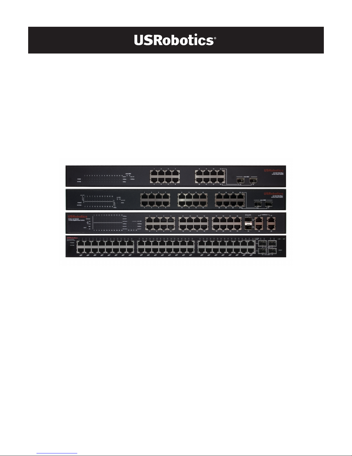
Introduction
This guide covers installation of the following Gigabit Smart Switch models:
! 7624
A—24-Port 10/100 PoE + 4-Port Gigabit Smart Switch
! 7716
A—10/100/1000 Mbps 16-Port Smart Switch
! 7724
A—10/100/1000 Mbps 24-Port Smart Switch
! 7748—10/100/1000 Mbps 48-Port Smart Switch
Package Contents
Physical Features
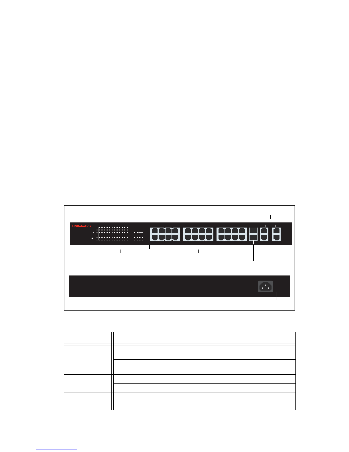
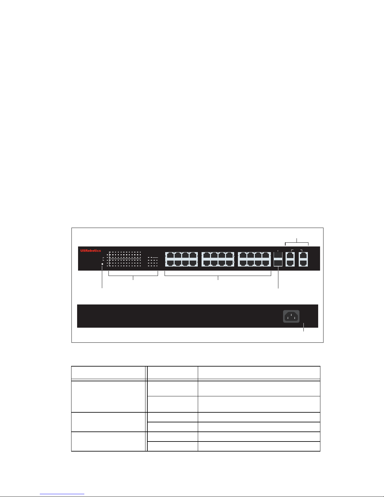
7624A Front, Back, and LEDs
Model 7624A. 24-Port 10/100 PoE + 4-Port Gigabit Smart Switch.
7624
A LEDs
! Smart Switch ! 2 Mounting Brackets and Screws
! Power Cord ! USRobotics Installation CD-ROM
! 4 Rubber Feet ! Quick Installation Guide
LED State Condition
PWR MAX
On Not enough power for additional PoE-powered
device
Off Enough power for additional PoE-powered
device
FAN
OK Fan is working
Fail Fan is not working
PWR
On Receiving power
Off Not receiving power
AC IN
LEDs PoE ports
Power connector
1 3 5 7
PWR
SYS
Fail
FAN
PWR MAX
OK
1 3 5 7 9 11 13 15 17 19 21 23
2 4 6 8 10 12 14 16 18 20 22 24 25 26 27 28
1000BASE-T
100Mbps
Link/ACT
PoE Status
100Mbps
Link/ACT
PoE Status
1000Mbps
Link/ACT
100Mbps
mini-GBIC
2 4 6 8
9 11 13 15
10 12 14 16
17 19 21 23
18 20 22 24
RESET
24-Port 10/100 PoE
+ 4-Port Gigabit Smart Switch
26 26 28
25 27
25 mini-GBIC
Reset button
Gigabit Ethernet ports
GBIC ports
Page 6

2
English
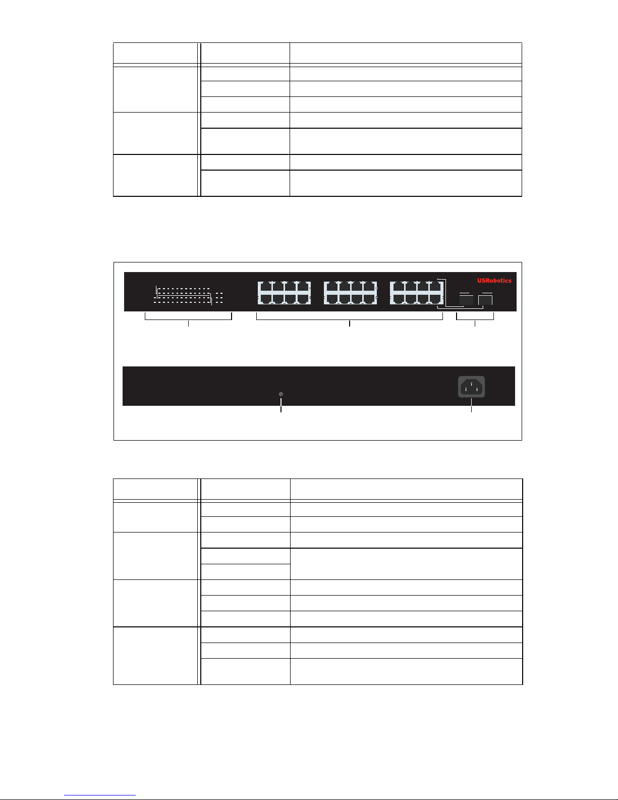
7716A Front, Back, and LEDs
Model 7716A. 10/100/1000 Mbps 16-Port Smart Switch.
7716
A LEDs
SYS
Blinking CPU is working
On
CPU is not working
Off
100Mbps
On Link rate is 100 Mbps
Off Link rate is 10 Mbps or 1000 Mbps, or no active
device is connected to the port
Link/ACT
On Link is up
Blinking Port is transmitting or receiving data
Off Link is down
PoE Status
Green Port is supplying power to the connected
device
Red Port cannot supply power to the connected
device
Off No PoE-compatible device is connected
mini-GBIC
On Mini-GBIC connection is active
Off Mini-GBIC connection is not active
1000 Mbps
On Link rate is 1000 Mbps
Off Link rate is 10 Mbps or 100 Mbps, or no active
device is connected to the port
LED State Condition
POWER
On Receiving power
Off Not receiving power
SYSTEM
Blinking CPU is working
On
CPU is not working
Off
LED State Condition
RESET
AC LINE
100-240VAC
50-60 Hz,1.2A
1
53
7
13 159
11
264 8 14 1610 12
POWER
SYSTEM
Link/ACT
1000Mbps
100Mbps
1000Mbps
Link / ACT
1234567
89
10
11 121314
15 1516 16
15 16
mini-GBIC
mini-GBIC
10/100/1000 Mbps
16-Port Smart Switch
LEDs Ethernet ports GBIC
ports
Reset button Power connector
Page 7
English
3
7724A Front, Back, and LEDs
Model 7724A. 10/100/1000 Mbps 24-Port Smart Switch.
7724
A LEDs
Link/ACT
On Link is up
Blinking Port is transmitting or receiving data
Off Link is down
1000 Mbps
On Link rate is 1000 Mbps
Off Link rate is 10 Mbps or 100 Mbps, or no active
device is connected to the port
100Mbps
On Link rate is 100 Mbps
Off Link rate is 10 Mbps or 1000 Mbps, or no active
device is connected to the port
LED State Condition
POWER
On Receiving power
Off Not receiving power
SYSTEM
Blinking CPU is working
On
CPU is not working
Off
Link/ACT
On Link is up
Blinking Port is transmitting or receiving data
Off Link is down
SPEED
Amber Link rate is 100 Mbps
Green Link rate is 1000 Mbps
Off Link rate is 10 Mbps or no active device is con-
nected to the port
LED State Condition
LEDs Ethernet ports GBIC
ports
Reset button Power connector
SPEED
Link/ACT
POWER
SYSTEM
SPEED
Link / ACT
23
24
mini-GBIC
1357
2468
9111315 17192123
10 12 14 16 18 20 22 24
23 24
mini-GBIC
10/100/1000 Mbps
24-Port Smart Switch
24
6 8 10
12 14
16 18 20
22 24
13
5 7 9
11 13
15 17 19
21 23
RESET
AC LINE
100-240VAC
50-60 Hz,1.2A
Page 8
4
English
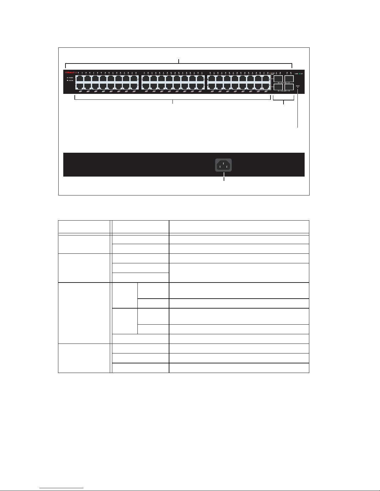
7748 Front, Back, and LEDs
Model 7748. 10/100/1000 Mbps 48-Port Smart Switch.
7748 LEDs
Default Values
All of the smart switches documented in this guide have the following default
values:
IP address:
192.168.0.1
Password: admin
LED State Condition
POWER
On Receiving power
Off Not receiving power
SYSTEM
Blinking CPU is working
On
CPU is not working
Off
1–48
(Ethernet)
Green Solid or
blinking
Link rate is 1000 Mbps
Blinking Port is transmitting or receiving data
Amber Solid or
blinking
Link rate is 10 Mbps or 100 Mbps
Blinking Port is transmitting or receiving data
Off Link is down
45–48
mini-GBIC
On Mini-GBIC module is installed and connected
Blinking Port is transmitting or receiving data
Off No mini-GBIC module is installed
10/100/1000 Mbps
48-Port Smart Switch
LEDs
Ethernet ports
GBIC
ports
Reset button
Power connector
AC LINE 100-240 VAC
50-60Hz 1.4A
Page 9
English
5
System Requirements
To install the switch, you need the following:
! A computer with an Ethernet adapter installed
! An Ethernet cable
For access to the switch’s Web User Interface, you need the following:
! A computer with an Ethernet adapter installed
! An HTML 4.01-compliant Web Browser (such as Internet Explorer 5.5 or
later or Netscape 8.0 or later) with JavaScript enabled
To use the Smart Switch Configuration Utility, the computer must be running
one of the following operating systems: Windows Vista™, Windows® XP, or
Windows® 2000. If you are not using one of these operating systems, you can
perform all configuration functions through the Web User Interface.
Installation
Step One: Mount the Hardware
The switch can be mounted on a flat surface or on an equipment rack.
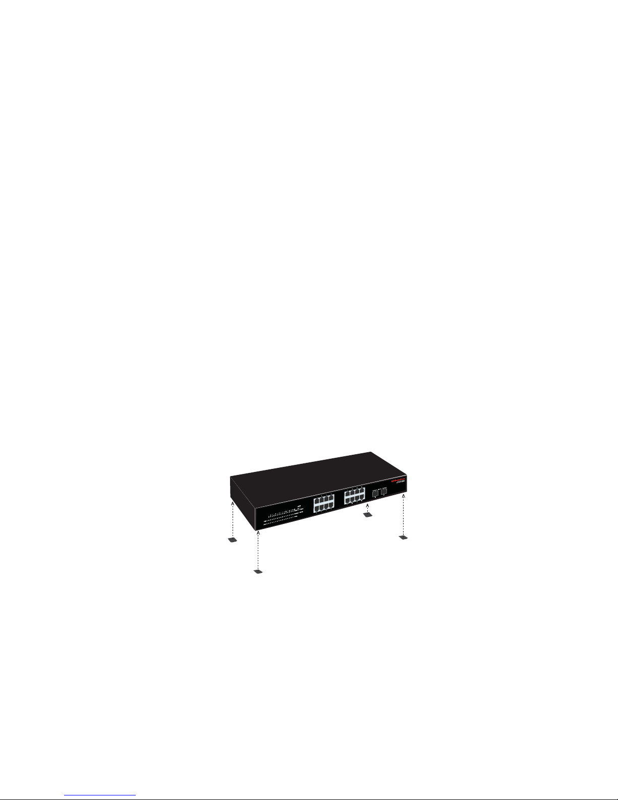
Surface Mounting
Attach the rubber feet to the bottom of each device. Install the Switch on a
sturdy, level surface that can support its weight.
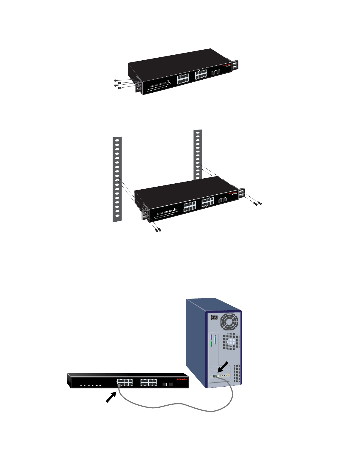
Rack Mounting
You can mount the switch on an EIA standard-size, 19-inch rack.
Page 10
6
English
1. Attach a bracket to each side of the switch, and secure the brackets with
the provided screws:
2. Use screws provided with the equipment rack to mount the switch in the
rack.:
Step Two: Attach Cables
1. Use an Ethernet cable to connect any Ethernet port on the switch to the
Ethernet port on a computer. The computer will be used to set the switch’s
IP address.
1537
13 159
11
264 8 14 1610 12
POWER
SYSTEM
Link/ACT
1000Mbps
100Mbps
1000Mbps
Link / ACT
1234567
89
10
11 121314
15 1516 16
15 16
mini-GBIC
mini-GBIC
10/100/1000 Mbps
16-Port Smart Switch
Page 11
English
7
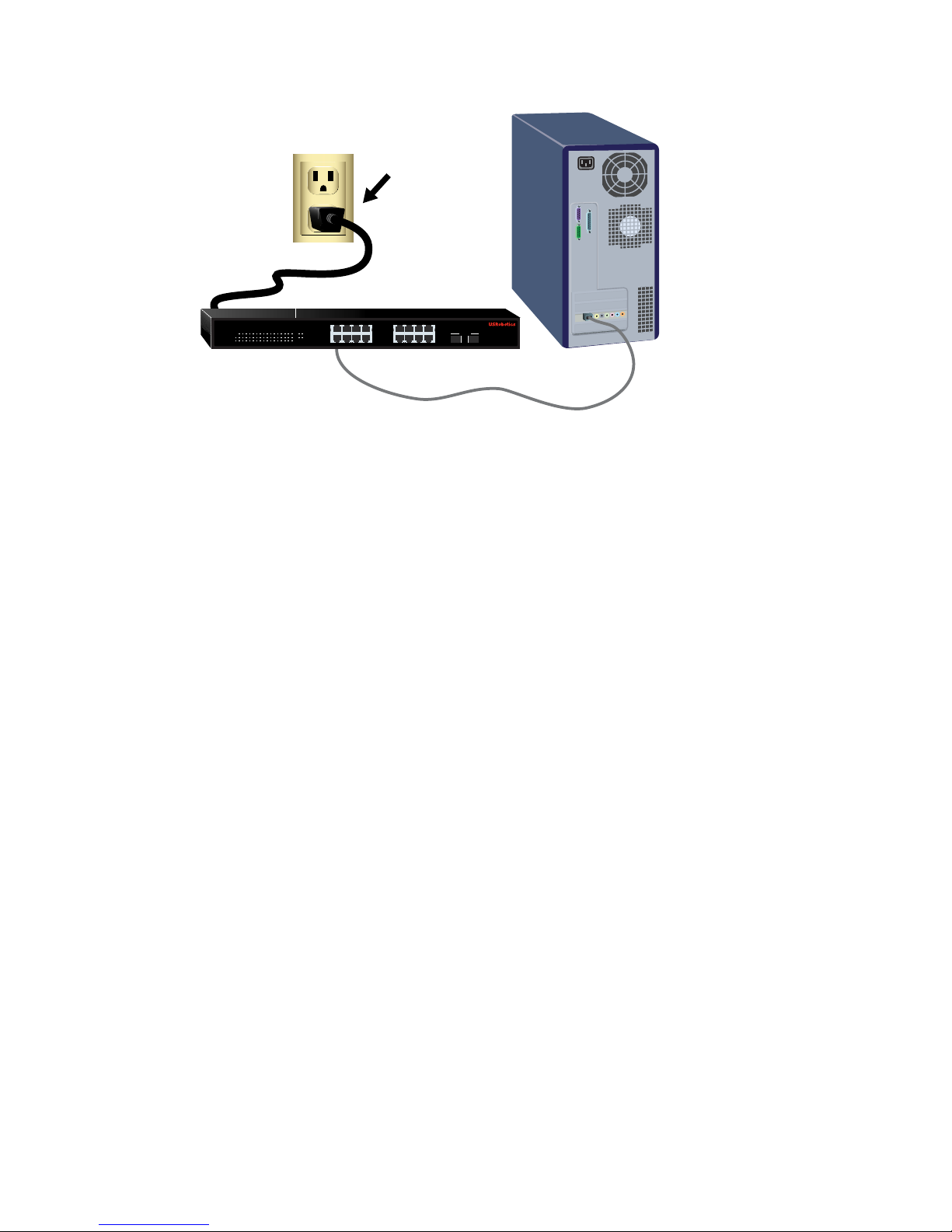
2. Connect the power cord to the 100-240VAC port on the switch, then plug
the power cord into a standard power outlet.
Step Three: Assign an IP Address to the Switch
If you are using an operating system other than Windows, see the User Guide on
the USRobotics Installation CD-ROM for instructions on assigning an IP
address to the switch.
If you are using a Windows operating system, the Smart Switch Configuration
Utility is the easiest way to set up the switch’s basic configuration. For information about other features available in the utility, see the User Guide on the
USRobotics Installation CD-ROM.
Install the Smart Switch Configuration Utility
1. Insert the USRobotics Installation CD-ROM in the CD or DVD drive.
If the CD doesn’t start automatically, start it manually as follows:
A. Windows Vista: Click Windows
Start > Computer.
Windows XP: Click Windows Start > My Computer.
Windows 2000: On the desktop, double-click
My Computer.
B. Double-click the CD drive.
2. Follow the on-screen instructions to install the Smart Switch Configuration
Utility.
Assign the IP Address
1. Start the Smart Switch Configuration Utility as follows:
1537
13 159
11
264 8 14 1610 12
POWER
SYSTEM
Link/ACT
1000Mbps
100Mbps
1000Mbps
Link / ACT
1234567
89
10
11 121314
15 1516 16
15 16
mini-GBIC
mini-GBIC
10/100/1000 Mbps
16-Port Smart Switch
Page 12
8
English
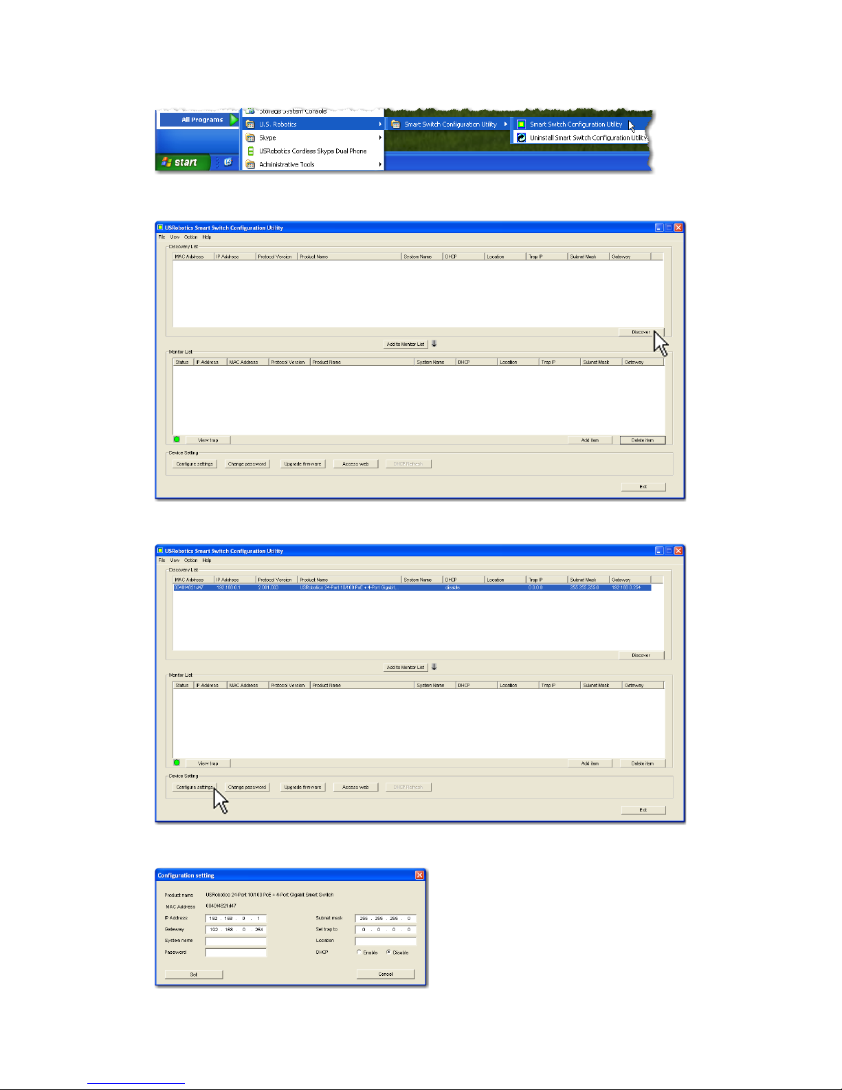
Click Windows Start > Programs > USRobotics > Smart Switch
Configuration Utility as shown below:
2. Click Discover to find the smart switch.
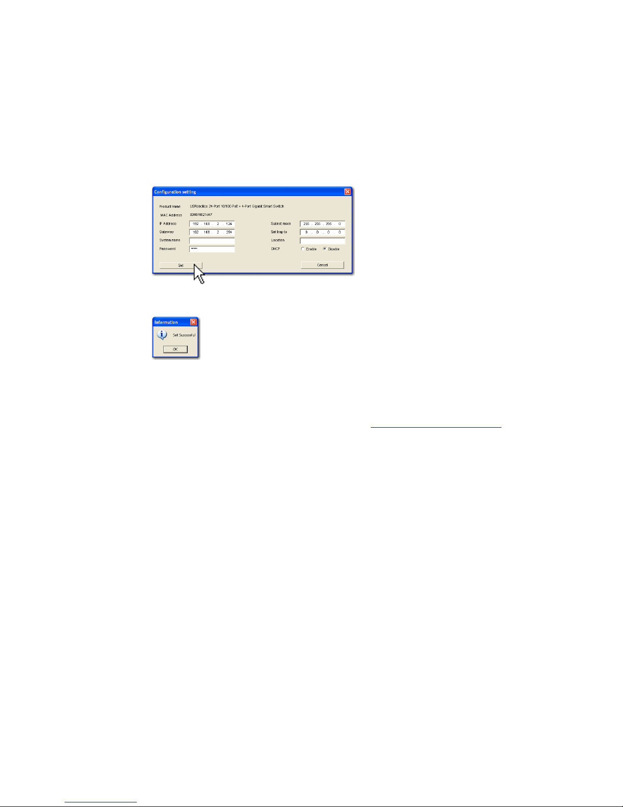
3. Click the smart switch entry to select it; then click Configure Settings:
The Configuration setting window appears:
Page 13
English
9
4. You can assign a static IP address to the switch or configure the switch to get
its address from a DHCP server.
Setting a Static IP Address:
A. Enter the IP Address that you want the switch to have.
B. Enter the Gateway address of the network to which you will connect the
switch.
C. In Password, enter
admin.
D. Click Set:
The utility confirms the configuration of the switch:
The switch is now accessible at its new IP address.
Congratulations. You have successfully completed the installation procedure. Please register your Gigabit Smart Switch at
www.usr.com/productreg/
.
You can now connect the switch to the network and access its Web User
Interface to configure other features of the switch. For more information about
using the Web User Interface, see the User Guide on the USRobotics Installation
CD-ROM.
Troubleshooting
General
This procedure addresses a number of symptoms that you might experience
during installation:
1. Verify that all cables are connected properly.
2. Ensure that the power outlet to which the switch is connected is a live outlet.
3. Restart the switch by removing and then reconnecting its power cable.
4. Consider the following environmental factors:
A. Install the switch in a cool and dry place. For acceptable temperature and
humidity operating ranges, see the User Guide on the USRobotics Installation CD-ROM.
Page 14

10
English
B. Install the switch in a site free from strong electromagnetic field genera-
tors (such as motors), vibration, dust, and direct exposure to sunlight.
C. Leave at least 10cm of space at the front and rear of the switch for venti-
lation.
Note:If you decide to reset the switch, record the configuration settings first.
Resetting the switch causes all values to revert to their factory settings.
If the switch does not appear in the Discovery List:
1. Check the LEDs on the switch:
" If the Power LED is not on, check the power cable and ensure that it is
connected to a live outlet. The switch uses 100-240 Volts AC.
" If the System LED is not blinking, try rebooting the switch. If rebooting
does not solve the problem, press the Reset button on the switch.
" If no LED indicates link or activity for the Ethernet port connected to
the computer, check your Ethernet cable.
2. Make sure your computer has an IP address.
3. If you are using a firewall on your computer, configure it to allow the Smart
Switch Configuration Utility. The utility uses UDP packets with destination
port 64515 to communicate with the switches.
Additional Information
For regulatory and warranty information, see the User Guide on the
USRobotics Installation CD-ROM.
For operation and configuration information, see the User Guide on the
USRobotics Installation CD-ROM.
For additional troubleshooting and technical support, see:
1. The User Guide on the USRobotics Installation CD-ROM.
2. The Support section of the USRobotics Web site at
www.usr.com/support/
.
Many of the most common difficulties that users experience have been
addressed in the FAQ and Troubleshooting Web pages for your Smart
Switch. The Support pages also contain current support contact information
and documentation.
3. The support contact information on the last page of this guide.
Page 15
Italiano
11
Italiano
Introduzione
Questa Guida contiene informazioni sui seguenti modelli Gigabit Smart Switch:
! 7624
A—24-Port 10/100 PoE + 4-Port Gigabit Smart Switch
! 7716
A—10/100/1000 Mbps 16-Port Smart Switch
! 7724
A—10/100/1000 Mbps 24-Port Smart Switch
! 7748
—10/100/1000 Mbps 48-Port Smart Switch
Contenuto della confezione
Caratteristiche del prodotto
7624A - Fronte, retro e LED
Modello 7624A. 24-Port 10/100 PoE + 4-Port Gigabit Smart Switch.
LED di 7624
A
! Smart Switch ! 2 staffe di montaggio e viti
! Cavo di alimentazione ! CD-ROM di installazione USRobotics
! 4 piedini di gomma ! Guida all'installazione rapida
LED Stato Condizione
PWR MAX
(Alimentazione max)
Acceso Alimentazione non sufficiente per
dispositivo PoE aggiuntivo
Spento Alimentazione sufficiente per
dispositivo PoE aggiuntivo
FAN (Ventilatore)
OK Ventilatore funzionante
Fail (Errore) Ventilatore non funzionante
PWR (Alimentazione)
Acceso Alimentato
Spento Non alimentato
AC IN
LED Porte PoE
Connettore di alimentazione
1 3 5 7
PWR
SYS
Fail
FAN
PWR MAX
OK
1 3 5 7 9 11 13 15 17 19 21 23
2 4 6 8 10 12 14 16 18 20 22 24 25 26 27 28
1000BASE-T
100Mbps
Link/ACT
PoE Status
100Mbps
Link/ACT
PoE Status
1000Mbps
Link/ACT
100Mbps
mini-GBIC
2 4 6 8
9 11 13 15
10 12 14 16
17 19 21 23
18 20 22 24
RESET
24-Port 10/100 PoE
+ 4-Port Gigabit Smart Switch
26 26 28
25 27
25 mini-GBIC
Tasto Reset (Ripristino)
Porte Ethernet Gigabit
Porte GBIC
Page 16

12
Italiano
7716A - Fronte, retro e LED
Modello 7716A. 10/100/1000 Mbps 16-Port Smart Switch.
LED di 7716
A
SYS (Sistema)
Lampeggiante CPU funzionante
Acceso
CPU non funzionante
Spento
100Mbps
Acceso Velocità di collegamento: 100 Mbps
Spento Velocità di collegamento di 10 Mbps o
1000 Mbps, o nessun dispositivo attivo
collegato alla porta
Link/ACT
(Collegamento/
attività)
Acceso Collegamento attivato
Lampeggiante Trasmissione o ricezione di dati in corso
Spento Collegamento non attivato
PoE Status (Stato PoE)
Verde Dispositivo connesso alimentato
Rosso Dispositivo connesso non alimentato
Spento Non è connesso alcun dispositivo
compatibile con PoE
mini-GBIC
Acceso Connessione Mini-GBIC attiva
Spento Connessione Mini-GBIC non attiva
1000 Mbps
Acceso Velocità di collegamento: 1000 Mbps
Spento Velocità di collegamento di 10 Mbps o
100 Mbps, o nessun dispositivo attivo
collegato alla porta
LED Stato Condizione
POWER
(Alimentazione)
Acceso Alimentato
Spento Non alimentato
SYSTEM
(Sistema)
Lampeggiante CPU funzionante
Acceso
CPU non funzionante
Spento
LED Stato Condizione
RESET
AC LINE
100-240VAC
50-60 Hz,1.2A
1
53
7
13 159
11
264 8 14 1610 12
POWER
SYSTEM
Link/ACT
1000Mbps
100Mbps
1000Mbps
Link / ACT
1234567
89
10
11 121314
15 1516 16
15 16
mini-GBIC
mini-GBIC
10/100/1000 Mbps
16-Port Smart Switch
LED Porte Ethernet Porte GBIC
Tasto Reset (Ripristino) Connettore di alimentazione
Page 17

Italiano
13
7724A - Fronte, retro e LED
Modello 7724A. 10/100/1000 Mbps 24-Port Smart Switch.
LED di 7724
A
Link/ACT
(Collegamento/
attività)
Acceso Collegamento attivato
Lampeggiante Trasmissione o ricezione di dati in corso
Spento Collegamento non attivato
1000 Mbps
Acceso Velocità di collegamento: 1000 Mbps
Spento Velocità di collegamento di 10 Mbps o 100
Mbps, o nessun dispositivo attivo collegato
alla porta
100 Mbps
Acceso Velocità di collegamento: 100 Mbps
Spento Velocità di collegamento di 10 Mbps o 1000
Mbps, o nessun dispositivo attivo collegato
alla porta
LED Stato Condizione
POWER
(Alimentazione)
Acceso Alimentato
Spento Non alimentato
SYSTEM
(Sistema)
Lampeggiante CPU funzionante
Acceso
CPU non funzionante
Spento
Link/ACT
(Collegamento/
attività)
Acceso Collegamento attivato
Lampeggiante Trasmissione o ricezione di dati in corso
Spento Collegamento non attivato
SPEED (Velocità)
Ambra Velocità di collegamento: 100 Mbps
Verde Velocità di collegamento: 1000 Mbps
Spento Velocità di collegamento di 10 Mbps, o
nessun dispositivo attivo collegato alla
porta
LED Stato Condizione
LED Porte Ethernet Porte GBIC
Tasto Reset (Ripristino) Connettore di alimentazione
SPEED
Link/ACT
POWER
SYSTEM
SPEED
Link / ACT
23
24
mini-GBIC
1357
2468
9111315 17192123
10 12 14 16 18 20 22 24
23 24
mini-GBIC
10/100/1000 Mbps
24-Port Smart Switch
24
6 8 10
12 14
16 18 20
22 24
13
5 7 9
11 13
15 17 19
21 23
RESET
AC LINE
100-240VAC
50-60 Hz,1.2A
Page 18

14
Italiano
7748 - Fronte, retro e LED
Modello 7748. 10/100/1000 Mbps 48-Port Smart Switch.
LED di 7748
Valori predefiniti
Tutti gli Smart Switch a cui si riferisce questa Guida presentano le seguenti
impostazioni predefinite:
Indirizzo IP:
192.168.0.1
Password: admin
LED Stato Condizione
POWER
(Alimentazione)
Acceso Alimentato
Spento Non alimentato
SYSTEM
(Sistema)
Lampeggiante CPU funzionante
Acceso
CPU non funzionante
Spento
1–48
(Ethernet)
Verde Acceso o
lampeggiante
Velocità di collegamento: 1000 Mbps
Lampeggiante Trasmissione o ricezione di dati in corso
Ambra Acceso o
lampeggiante
Velocità di collegamento: 10 o 100 Mbps
Lampeggiante Trasmissione o ricezione di dati in corso
Spento Collegamento non attivato
45–48
mini-GBIC
Acceso Il modulo Mini-GBIC è installato e
connesso
Lampeggiante Trasmissione o ricezione di dati in corso
Spento Non è installato alcun modulo Mini-GBIC
10/100/1000 Mbps
48-Port Smart Switch
LED
Porte Ethernet
Porte GBIC
Tasto Reset (Ripristino)
Connettore di alimentazione
AC LINE 100-240 VAC
50-60Hz 1.4A
Page 19

Italiano
15
Requisiti del sistema
Per installare il dispositivo, è necessario disporre di:
! Un computer con scheda Ethernet installata
! Cavo Ethernet
Per accedere all'interfaccia utente Web dello switch, è necessario disporre di:
! Un computer con scheda Ethernet installata
! Browser Web compatibile con HTML 4.01 (Internet Explorer 5.5 o versione
successiva oppure Netscape 8.0 o versione successiva) e con JavaScript
abilitato
Per usare l'utilità di configurazione Smart Switch, il computer deve disporre di
uno dei seguenti sistemi operativi: Windows Vista™, Windows® XP o
Windows® 2000. Se si utilizza un sistema operativo diverso, è possibile eseguire
tutte le funzioni di configurazione tramite l'interfaccia utente Web.
Installazione
Fase uno: installazione dell'hardware
È possibile montare lo switch su una superficie piana o un rack.
Montaggio su superficie piana
Fissare i piedini di gomma sotto a ciascun dispositivo. Installare lo switch su
una superficie piana e solida, in grado di supportarne il peso.
Montaggio su rack
È possibile montare lo switch su rack di dimensioni standard EIA di 19
pollici.
Page 20

16
Italiano
1. Posizionare una staffa su ciascun lato dello switch e fissarla con le viti
fornite in dotazione:
2. Usare le viti fornite in dotazione con il rack per fissare lo switch nel rack:
Fase due: collegamento dei cavi
1. Usare un cavo Ethernet per collegare una porta Ethernet dello switch alla
porta Ethernet del computer. È necessario usare il computer per impostare
l'indirizzo IP dello switch.
1537
13 159
11
264 8 14 1610 12
POWER
SYSTEM
Link/ACT
1000Mbps
100Mbps
1000Mbps
Link / ACT
1234567
89
10
11 121314
15 1516 16
15 16
mini-GBIC
mini-GBIC
10/100/1000 Mbps
16-Port Smart Switch
Page 21

Italiano
17
2. Collegare il cavo di alimentazione alla porta 100-240VAC dello switch, quindi
collegare l'adattatore di alimentazione a una presa di corrente standard.
Fase tre: assegnazione dell'indirizzo IP allo switch
Se si utilizza un sistema operativo diverso da Windows, consultare la Guida utente
sul CD-ROM di installazione USRobotics per istruzioni sull'assegnazione di un
indirizzo IP allo switch.
Se si utilizza un sistema operativo Windows, utilizzare l'utilità di configurazione
Smart Switch per impostare la configurazione di base dello switch. Per
informazioni su altre funzioni disponibili nell'utilità, consultare la
Guida utente sul CD-ROM di installazione USRobotics.
Installazione dell'utilità di configurazione Smart Switch.
1. Inserire il CD-ROM di installazione USRobotics nell'unità CD-ROM o DVD.
Se l'installazione non si avvia automaticamente, eseguire la procedura
manualmente, come indicata di seguito:
A. Utenti Windows Vista: fare clic su
Start > Computer.
Windows XP: fare clic su
Start > Risorse del computer.
Utenti Windows 2000: sul desktop, fare doppio clic su
Risorse del
computer
.
B. Fare doppio clic sull'unità CD-ROM.
2. Installare l'utilità di configurazione Smart Switch seguendo le istruzioni a
schermo.
Assegnazione dell'indirizzo IP
1. Avviare l'utilità di configurazione Smart Switch seguendo questa procedura:
1537
13 159
11
264 8 14 1610 12
POWER
SYSTEM
Link/ACT
1000Mbps
100Mbps
1000Mbps
Link / ACT
1234567
89
10
11 121314
15 1516 16
15 16
mini-GBIC
mini-GBIC
10/100/1000 Mbps
16-Port Smart Switch
Page 22

18
Italiano
Fare clic su Start > Programmi > USRobotics > utilità di
configurazione Smart Switch come indicato qui sotto:
2. Fare clic su Discovery (Rilevamento) per cercare Smart Switch.
3. Fare clic sulla voce Smart Switch per selezionarla, quindi fare clic su
Configure Settings (Configura impostazioni):
Viene visualizzata la finestra delle impostazioni di configurazione:
Page 23

Italiano
19
4. È possibile assegnare un indirizzo IP statico allo switch o configurare lo
switch in modo da ricevere l'indirizzo dal server DHCP.
Impostazione dell'indirizzo IP statico:
A. Inserire l'indirizzo che si desidera assegnare allo switch nel campo IP
address.
B. Nel campo Gateway, inserire l'indirizzo della rete a cui si connetterà lo
switch.
C. Nel campo Password, digitare
admin.
D. Fare clic s u Set (Imposta).
L'utilità conferma la configurazione dello switch:
Lo switch è ora accessibile al nuovo indirizzo IP.
Congratulazioni. La procedura di installazione è completa. Registrare
Gigabit Smart Switch alla pagina
www.usr.com/productreg/
.
È ora possibile connettere lo switch alla rete e accedere all'interfaccia utente Web
per configurare lo switch. Per ulteriori informazioni riguardo all'uso
dell'interfaccia utente Web, consultare la Guida utente sul CD-ROM di
installazione USRobotics.
Risoluzione di problemi
Generali
Questa procedura può risolvere alcuni problemi che potrebbero verificarsi
durante l'installazione:
1. Verificare che tutti i cavi siano collegati correttamente.
2. Assicurarsi che la presa di corrente a cui è collegato lo switch sia funzionante.
3. Riavviare lo switch scollegando e ricollegando i cavi di alimentazione.
4. Prendere in considerazione i seguenti fattori ambientali:
A. Installare lo switch in un luogo fresco e asciutto. Per informazioni su
livelli di temperatura e umidità accettabili, consultare la Guida utente sul
CD-ROM di installazione USRobotics.
Page 24

20
Italiano
B. Installare lo switch in un luogo in cui non siano presenti generatori di
campi magnetici (come motori), vibrazioni, polvere ed esposizione diretta
al sole.
C. Lasciare almeno 10 cm di spazio di fronte e dietro allo switch per favorire
un'appropriata ventilazione.
Nota:prima di reimpostare lo switch, salvare le opzioni di configurazione.
Reimpostando lo switch vengono ripristinate tutte le impostazioni
predefinite.
Se lo switch non viene visualizzato in Discovery List (Elenco
rilevazione):
1. Controllare i LED dello switch:
" Se il LED POWER non è acceso, controllare il cavo di alimentazione e
assicurarsi che sia collegato a una presa funzionante. Lo switch usa
100-240 V CA.
" Se il LED System non lampeggia, riprovare a riavviare lo switch. Se ciò
non risolve il problema, premere il tasto Reset dello switch.
" Se i LED non indicano la presenza di connessioni o attività per la porta
Ethernet collegata al computer, controllare il cavo Ethernet.
2. Assicurarsi che il computer disponga di un indirizzo IP.
3. Se si utilizza un firewall sul computer, configurarlo per abilitare l'utilità di
configurazione Smart Switch, che utilizza pacchetti UDP con la porta di
destinazione 64515 per comunicare con gli switch.
Informazioni aggiuntive
Per informazioni su conformità e garanzia, consultare la Guida utente sul CD-
ROM di installazione USRobotics.
Per informazioni su funzionamento e configurazione, consultare la Guida
utente sul CD-ROM di installazione USRobotics.
Per risoluzione di problemi e assistenza tecnica, consultare:
1. La Guida utente sul CD-ROM di installazione USRobotics.
2. La sezione relativa al supporto tecnico del sito Web di USRobotics
all'indirizzo www.usr.com/support/
.
La maggior parte dei problemi riscontrati dagli utenti è trattata nelle pagine
del sito Web che riportano le domande frequenti (FAQ) e la risoluzione di
problemi per Smart Switch. Le pagine di supporto contengono inoltre
informazioni per contattare il servizio di assistenza e documenti utili.
3. L'ultima pagina di questa guida, che contiene informazioni sul servizio di
assistenza.
Page 25

Türkçe
21
Türkçe
Giriş
Bu kõlavuz, aşağõdaki Gigabit Smart Switch modellerini kapsamaktadõr:
! 7624
A—24-Port 10/100 PoE + 4-Port Gigabit Smart Switch
! 7716
A—10/100/1000 Mbps 16-Port Smart Switch
! 7724
A—10/100/1000 Mbps 24-Port Smart Switch
! 7748—10/100/1000 Mbps 48-Port Smart Switch
Ambalaj İçeriği
Fiziksel Özellikler
7624A Ön, Arka ve LED'ler
Model 7624A. 24-Port 10/100 PoE + 4-Port Gigabit Smart Switch.
7624
A LED'ler
! Smart Switch ! 2 Montaj Braketi ve Vidalar
! Güç Kablosu ! USRobotics Kurulum CD-ROM'u
! 4 Plastik Ayak ! Hõzlõ Kurulum Kõlavuzu
LED Durum Koşul
PWR MAX
Açõk Ek PoE enerjili cihaz için yeterli güç yok
Kapalõ Ek PoE enerjili cihaz için yeterli güç var
FAN
Tam am Fa n ça lõşõyor
BaşarõsõzFan çalõşmõyor
PWR
Açõk Güç alõnõyor
Kapalõ Güç alõnmõyor
AC IN
LED'ler PoE portlarõ
Güç konnektörü
1 3 5 7
PWR
SYS
Fail
FAN
PWR MAX
OK
1 3 5 7 9 11 13 15 17 19 21 23
2 4 6 8 10 12 14 16 18 20 22 24 25 26 27 28
1000BASE-T
100Mbps
Link/ACT
PoE Status
100Mbps
Link/ACT
PoE Status
1000Mbps
Link/ACT
100Mbps
mini-GBIC
2 4 6 8
9 11 13 15
10 12 14 16
17 19 21 23
18 20 22 24
RESET
24-Port 10/100 PoE
+ 4-Port Gigabit Smart Switch
26 26 28
25 27
25 mini-GBIC
Reset (Sõfõrlama) Butonu
Gigabit Ethernet portlarõ
GBIC portlarõ
Page 26

22
Türkçe
7716A Ön, Arka ve LED'ler
Model 7716A. 10/100/1000 Mbps 16-Port Smart Switch.
7716
A LED'ler
SYS
Yanõp sönüyor CPU çalõşõyor
Açõk
CPU çalõşmõyor
Kapalõ
100Mbps
AçõkBağlantõ hõzõ 100 Mbps
Kapalõ Bağlantõ hõzõ 10 Mbps ya da 1000 Mbps
veya porta bağlõ aktif cihaz yok
Link/ACT
AçõkBağlantõ çalõşõyor
Yanõp sönüyor Port veri iletiyor ya da alõyor
Kapalõ Bağlantõ çalõşmõyor
PoE Status
Yeşil Port, bağlanan cihaza güç sağlõyor
Kõrmõzõ Port, bağlanan cihaza güç sağlayamõyor
Kapalõ PoE uyumlu bir cihaz bağlõ değil
mini-GBIC
Açõk Mini-GBIC bağlantõsõ devrede
Kapalõ Mini-GBIC bağlantõsõ devrede değil
1000 Mbps
AçõkBağlantõ hõzõ 1000 Mbps
Kapalõ Bağlantõ hõzõ 10 Mbps ya da 100 Mbps veya
porta bağlõ aktif cihaz yok
LED Durum Koşul
POWER
Açõk Güç alõnõyor
Kapalõ Güç alõnmõyor
SYSTEM
Yanõp sönüyor CPU çalõşõyor
Açõk
CPU çalõşmõyor
Kapalõ
Link/ACT
AçõkBağlantõ çalõşõyor
Yanõp sönüyor Port veri iletiyor ya da alõyor
Kapalõ Bağlantõ çalõşmõyor
LED Durum Koşul
RESET
AC LINE
100-240VAC
50-60 Hz,1.2A
1
53
7
13 159
11
264 8 14 1610 12
POWER
SYSTEM
Link/ACT
1000Mbps
100Mbps
1000Mbps
Link / ACT
1234567
89
10
11 121314
15 1516 16
15 16
mini-GBIC
mini-GBIC
10/100/1000 Mbps
16-Port Smart Switch
LED'ler Ethernet portu GBIC
portlarõ
Reset (Sõfõrlama) Butonu Güç konnektörü
Page 27

Türkçe
23
7724A Ön, Arka ve LED'ler
Model 7724A. 10/100/1000 Mbps 24-Port Smart Switch.
7724
A LED'ler
1000 Mbps
AçõkBağlantõ hõzõ 1000 Mbps
Kapalõ Bağlantõ hõzõ 10 Mbps ya da 100 Mbps veya
porta bağlõ aktif cihaz yok
100Mbps
AçõkBağlantõ hõzõ 100 Mbps
Kapalõ Bağlantõ hõzõ 10 Mbps ya da 1000 Mbps
veya porta bağlõ aktif cihaz yok
LED Durum Koşul
POWER
AçõkGüç alõnõyor
Kapalõ Güç alõnmõyor
SYSTEM
Yanõp sönüyor CPU çalõşõyor
Açõk
CPU çalõşmõyor
Kapalõ
Link/ACT
AçõkBağlantõ çalõşõyor
Yanõp sönüyor Port veri iletiyor ya da alõyor
Kapalõ Bağlantõ çalõşmõyor
SPEED
Sarõ Bağlantõ hõzõ 100 Mbps
Yeşil Bağlantõ hõzõ 1000 Mbps
Kapalõ Bağlantõ hõzõ 10 Mbps ya da porta bağlõ aktif
cihaz yok
LED Durum Koşul
LED'ler Ethernet portu GBIC
portlarõ
Reset (Sõfõrlama) Butonu Güç konnektörü
SPEED
Link/ACT
POWER
SYSTEM
SPEED
Link / ACT
23
24
mini-GBIC
1357
2468
9111315 17192123
10 12 14 16 18 20 22 24
23 24
mini-GBIC
10/100/1000 Mbps
24-Port Smart Switch
24
6 8 10
12 14
16 18 20
22 24
13
5 7 9
11 13
15 17 19
21 23
RESET
AC LINE
100-240VAC
50-60 Hz,1.2A
Page 28

24
Türkçe
7748 Ön, Arka ve LED'ler
Model 7748. 10/100/1000 Mbps 48-Port Smart Switch.
7748 LED'ler
Varsayõlan Değerler
Bu kõlavuzda belgelenen smart switch'in tamamõ, aşağõdaki varsayõlan
değerlere sahiptir:
IP adresi:
192.168.0.1
Şifre: admin
LED Durum Koşul
POWER
Açõk Güç alõnõyor
Kapalõ Güç alõnmõyor
SYSTEM
Yanõp sönüyor CPU çalõşõyor
Açõk
CPU çalõşmõyor
Kapalõ
1–48
(Ethernet)
Yeşil Yanõyor ya da
yanõp sönüyor
Bağlantõ hõzõ 1000 Mbps
Yanõp sönüyor Port veri iletiyor ya da alõyor
Sarõ Yanõyor ya da
yanõp sönüyor
Bağlantõ hõzõ 10 Mbps veya 100 Mbps
Yanõp sönüyor Port veri iletiyor ya da alõyor
Kapalõ Bağlantõ çalõşmõyor
45–48
mini-GBIC
Açõk Mini-GBIC modülü kurulu ve bağlõ
Yanõp sönüyor Port veri iletiyor ya da alõyor
Kapalõ Kurulu mini-GBIC modülü yok
10/100/1000 Mbps
48-Port Smart Switch
LED'ler
Ethernet portu
GBIC
portlarõ
Reset (Sõfõrlama)
Butonu
Güç konnektörü
AC LINE 100-240 VAC
50-60Hz 1.4A
Page 29

Türkçe
25
Sistem Gereksinimleri
Switch'i kurmak için aşağõdakiler gerekmektedir:
! Ethernet adaptörü kurulu bir bilgisayar
! Bir Ethernet kablosu
Switch'in İnternet Kullanõcõ Arayüzü'ne erişim için aşağõdakiler
gerekmektedir:
! Ethernet adaptörü kurulu bir bilgisayar
! Etkin JavaScript desteği bulunan HTML 4.01 uyumlu İnternet Tarayõcõ
(örneğin Internet Explorer 5.5 veya üzeri ya da Netscape 7.0 veya üzeri)
Smart Switch Yapõlandõrma Yardõmcõ Programõ kullanmak için, bilgisayar
listelenen işletim sistemlerinden birini kullanõyor olmalõdõr: Windows
Vista™, Windows® XP ya da Windows® 2000. Bu işletim sistemlerinden
birini kullanmõyorsanõz, tüm yapõlandõrma fonksiyonlarõnõ İnternet Kullanõcõ
Arayüzü üzerinden gerçekleştirebilirsiniz.
Kurulum
Birinci Adõm: Donanõmõ Monte edin
Switch, düz bir yüzeye ya da bir donanõm rafõna monte edilebilir.
Yüzeye Montaj
Plastik ayağõ her bir cihazõn alt kõsmõna takõn. Switch'i, ağõrlõğõnõ
taşõyabilecek sağlam, düz bir yüzeye monte edin.
Rafa Montaj
Switch'i, EIA standart boyutlu, 19 inçlik bir rafa monte edebilirsiniz.
Page 30

26
Türkçe
1. Switch'in yan taraflarõna bir braket takõn ve birlikte verilen vidalarõ
kullanarak braketleri sabitleyin:
2. Donanõm rafõyla birlikte verilen vidalarõ kullanarak switch'i rafa monte
edin:
İkinci Adõm: Kablolarõ Bağlayõn
1. Switch üzerindeki Ethernet portlarõnõ bir bilgisayarda bulunan Ethernet
portlarõna bağlamak için bir Ethernet kablosu kullanõn. Bilgisayar,
switch'in IP adresini ayarlamak için kullanõlacaktõr.
1537
13 159
11
264 8 14 1610 12
POWER
SYSTEM
Link/ACT
1000Mbps
100Mbps
1000Mbps
Link / ACT
1234567
89
10
11 121314
15 1516 16
15 16
mini-GBIC
mini-GBIC
10/100/1000 Mbps
16-Port Smart Switch
Page 31

Türkçe
27
2. Güç kablosunu, switch'deki 100-240 VAC portuna bağlayõn ve sonra da
güç kablosunu prize takõn.
Üçüncü Adõm: Switch'e bir IP Adresi Atayõn
Windows dõşõnda bir işletim sistemi kullanõyorsanõz, switch'e bir IP adresi
atama hakkõnda talimatlar için bkz. Kullanõm Kõlavuzu USRobotics Kurulum
CD-ROM’unda.
Bir Windows işletim sistemi kullanõyorsanõz Smart Switch Yapõlandõrma
Ya rd õmcõ Programõ, switch'in temel yapõlandõrmasõnõ yapmanõn en kolay
yoludur. Yardõmcõ programda bulunan diğer özellikler hakkõnda bilgi için bkz.
Kullanõm Kõlavuzu USRobotics Kurulum CD-ROM’unda.
Smart Switch Yapõlandõrma Yardõmcõ Programõ ürününü kurun
1. USRobotics Kurulum CD-ROM'u CD'sini, CD veya DVD sürücüye takõn.
CD otomatik olarak başlatõlmazsa aşağõdaki gibi manuel olarak başlatõn:
A. Windows Vista: Windows
Başlat > Bilgisayar seçeneklerini tõklatõn.
Windows XP: Windows
Başlat> Bilgisayarõm seçeneklerini tõklatõn
Windows 2000: Masaüstü üzerinde
Bilgisayarõm simgesini çift
tõklatõn.
B. CD sürücü simgesini çift tõklatõn.
2. Smart Switch Yapõlandõrma Yardõmcõ Programõ ürününü kurmak için
ekrandaki talimatlarõ izleyin.
IP Adresini Atayõn
1. Smart Switch Yapõlandõrma Yardõmcõ Programõ programõnõ aşağõdaki
şekilde başlatõn:
1537
13 159
11
264 8 14 1610 12
POWER
SYSTEM
Link/ACT
1000Mbps
100Mbps
1000Mbps
Link / ACT
1234567
89
10
11 121314
15 1516 16
15 16
mini-GBIC
mini-GBIC
10/100/1000 Mbps
16-Port Smart Switch
Page 32

28
Türkçe
Aşağõda gösterilen şekilde Windows Başlat > Programlar > USRobotics
> Smart Switch Yapõlandõrma Yardõmcõ Programõ seçeneklerini
tõklatõn:
2. Smart switch cihazõnõ bulmak için Discover (Keşfet) seçeneğini tõklatõn.
3. Smart switch girişini tõklatarak seçin ve ardõndan, Configure Settings
(Ayarlarõ Ya põlandõr) seçeneğini tõklatõn.
Ya põlandõrma ayar penceresi açõlõr:
Page 33

Türkçe
29
4. Switch'e, statik bir IP adresi atayabilir ya da adresi DHCP sunucusundan
almak için switch'i yapõlandõrabilirsiniz.
Statik IP Adresi Ayarlama:
A. Switch için bir IP Address (IP Adresi) girin.
B. Switch'i bağlayacağõnõz ağõn Gateway (Ağ Geçidi) adresini girin.
C. Password (Şifre) kõsmõna
admin girin.
D. Set (Ayarla) seçeneğini tõklatõn:
Yar dõmcõ program, switch yapõlandõrmasõnõ onaylar:
Switch'e artõk yeni IP adresi üzerinden erişilebilir.
Tebrikler. Kurulum prosedürü başarõyla tamamlanmõştõr. Gigabit Smart
Switch cihazõnõzõn kaydõnõ
www.usr.com/productreg/
adresinde gerçekleştirin.
Şimdi switch'i ağa bağlayabilir ve switch'in diğer özelliklerini yapõlandõrmak
için İnternet Kullanõcõ Arayüzü'e erişebilirsiniz. İnternet Kullanõcõ Arayüzü
kullanõmõ hakkõnda daha fazla bilgi için bkz. Kullanõm Kõlavuzu USRobotics
Kurulum CD-ROM’unda.
Sorun Giderme
Genel
Bu prosedür, kurulum sõrasõnda karşõlaşabileceğiniz bazõ sorunlarõ çözmek
içindir:
1. Tüm kablolarõn düzgün bağlandõğõndan emin olun.
2. Switch'in bağlõ olduğu elektrik prizinde elektrik olduğundan emin olun.
3. Switch'in güç kablosunu söküp tekrar bağlayarak switch'i yeniden
başlatõn.
4. Aşağõdaki ortam koşullarõnõ göz önünde bulundurun:
A. Switch'i, serin ve kuru bir yere monte edin. Kabul edilen çalõşma
sõcaklõğõ ve nem aralõğõ için bkz. Kullanõm Kõlavuzu USRobotics
Kurulum CD-ROM’unda.
Page 34

30
Türkçe
B. Switch'i, güçlü manyetik alan yaratan cihazlar (motorlar gibi), titreşim,
toz bulunmayan bir ortamda, doğrudan güneş õşõnlarõna maruz
kalmayacak şekilde monte edin.
C. Switch'in önünde ve arkasõnda havalandõrma için en az 10 cm boşluk
bõrakõn.
Not: Switch'i sõfõrlamak istediğinizde, önce yapõlandõrma ayarlarõnõ
kaydedin. Switch sõfõrlandõğõnda, tüm değerler fabrika ayarlarõna
döner.
Switch, Algõlama Listesi'nde yoksa:
1. Switch üzerindeki LED'leri kontrol edin:
" Güç LED'i yanmõyorsa, güç kablosunu kontrol edin ve bağlõ olduğu
prizde elektrik olduğundan emin olun. Switch 100-240 Volt AC güç
kullanõr.
" Sistem LED'i yanõp sönmüyorsa, switch'i yeniden başlatmayõ deneyin.
Yeniden başlatma sorunu çözmüyorsa, switch'deki Reset (Sõfõrla)
düğmesine basõn.
" Hiçbir LED bilgisayara bağlõ Ethernet portu için bağlantõ ya da etkinlik
göstermiyorsa, Ethernet kablonuzu kontrol edin.
2. Bilgisayarõn bir IP adresi olduğundan emin olun.
3. Bilgisayarõnõzda bir güvenlik duvarõ kullanõyorsanõz bunu, Smart Switch
Ya põlandõrma Yardõmcõ Programõ programõna izin verecek şekilde
yapõlandõrõn. Yardõmcõ program, switch'le iletişim kurmak için
hedef portu 64515 olan UDP paketleri kullanõr.
Ek Bilgiler
Yasal ve garantiyle ilgili bilgiler için bkz. Kullanõm Kõlavuzu USRobotics
Kurulum CD-ROM’unda.
Çalõşma ve yapõlandõrma hakkõnda bilgiler için, bkz. Kullanõm Kõlavuzu
USRobotics Kurulum CD-ROM’unda.
Diğer sorun giderme ve teknik destek için, bkz.:
1. Kullanõm Kõlavuzu USRobotics Kurulum CD-ROM’unda.
2. USRoboticsWeb sitesinin Destek bölümüne gidin:
www.usr.com/support/
.
Kullanõcõlarõn en yaygõn karşõlaştõğõ sorunlarõn çoğu, Smart SwitchSSS ve
Sorun Giderme İnternet sayfalarõnda açõklanmõştõr. Destek sayfalarõ ayrõca
geçerli destek iletişim bilgileri ve belgelerini içermektedir.
3. Bu kõlavuzun son sayfasõndaki destek iletişim bilgileri.
Page 35

Ελληνικά
31
Ελληνικά
Εισαγωγή
Ο οδηγός αυτός περιγράφει την εγκατάσταση των ακόλουθων μοντέλων
Gigabit Smart Switch:
! 7624
A—24-Port 10/100 PoE + 4-Port Gigabit Smart Switch
! 7716
A—10/100/1000 Mbps 16-Port Smart Switch
! 7724
A—10/100/1000 Mbps 24-Port Smart Switch
! 7748—10/100/1000 Mbps 48-Port Smart Switch
Περιεχόμενο συσκευασίας
Φυσικά χαρακτηριστικά
Πρόσοψη, πίσω όψη και λυχνίες LED μοντέλου 7624A
Μοντέλο 7624A. 24-Port 10/100 PoE + 4-Port Gigabit Smart Switch.
Λυχνίες LED μοντέλου 7624
A
! Smart Switch ! 2 στηρίγματα τοποθέτησης και βίδες
! Καλώδιο ρεύματος ! CD-ROM Εγκατάστασης της USRobotics
! 4 ελαστικές βάσεις ! Οδηγός γρήγορης εγκατάστασης
LED Kατάσταση Συνθήκες
PWR MAX
Αναμμένη Δεν υπάρχει αρκετή ισχύς για επιπλέον
συσκευή με τροφοδοσία PoE
Σβηστή Υπάρχει αρκετή ισχύς για επιπλέον συσκευή με
τροφοδοσία PoE
FAN
OK Ο ανεμιστήρας λειτουργεί
Fail Ο ανεμιστ ήρας δεν λειτουργεί
PWR
Αναμμένη Τροφοδοσία ρεύματος
Σβηστή Δεν γίνεται τροφοδοσία ρεύματος
AC IN
Λυχνίες LED Θύρες PoE
Βύσμα ρεύματος
1 3 5 7
PWR
SYS
Fail
FAN
PWR MAX
OK
1 3 5 7 9 11 13 15 17 19 21 23
2 4 6 8 10 12 14 16 18 20 22 24 25 26 27 28
1000BASE-T
100Mbps
Link/ACT
PoE Status
100Mbps
Link/ACT
PoE Status
1000Mbps
Link/ACT
100Mbps
mini-GBIC
2 4 6 8
9 11 13 15
10 12 14 16
17 19 21 23
18 20 22 24
RESET
24-Port 10/100 PoE
+ 4-Port Gigabit Smart Switch
26 26 28
25 27
25 mini-GBIC
Κουμπί Reset (Επαναφορά)
Θύρες Gigabit Ethernet
Θύρες GBIC
Page 36

32
Ελληνικά
Πρόσοψη, πίσω όψη και λυχνίες LED μοντέλου 7716A
Μοντέλο 7716A. 10/100/1000 Mbps 16-Port Smart Switch.
Λυχνίες LED μοντέλου 7716
A
SYS
Αναβοσβήνει Η μονάδα CPU λειτουργεί
Αναμμένη
Η μονάδα CPU δεν λειτουργεί
Σβηστή
100Mbps
Αναμμένη Η ταχύτητα σύνδεσης είναι 100 Mbps
Σβηστή Είτε η ταχύτητα σύνδεσης είναι 10 Mbps ή
1000 Mbps είτε καμία ενεργή συσκευή δεν είναι
συνδεδεμένη στη θύρα
Link/ACT
Αναμμένη Υπάρχει σύνδεση
Αναβοσβήνει Η θύρα μεταδίδει ή λαμβάνει δεδομένα
Σβηστή Δεν υπάρχει σύνδεση
PoE Status
Πράσινη Η θύρα τροφοδοτεί με ρεύμα τη συνδεδεμένη
συσκευή
Κόκκινη Η θύρα δεν μπορεί τροφοδοτήσει με ρεύμα τη
συνδεδεμένη συσκευή
Σβηστή Δεν είναι συνδεδεμένη καμία συσκευή συμβατή
με PoE
mini-GBIC
Αναμμένη Η σύνδεση Mini-GBIC είναι ενεργή
Σβηστή Η σύνδεση Mini-GBIC δεν είναι ενεργή
1000 Mbps
Αναμμένη Η ταχύτητα σύνδεσης είναι 1000 Mbps
Σβηστή Είτε η ταχύτητα σύνδεσης είναι 10 Mbps ή
100 Mbps είτε καμία ενεργή συσκευή δεν είναι
συνδεδεμένη στη θύρα
LED Kατάσταση Συνθήκες
POWER
Αναμμένη Τροφοδοσία ρεύματος
Σβηστή Δεν γίνεται τροφοδοσία ρεύματος
SYSTEM
Αναβοσβήνει Η μονάδα CPU λειτουργεί
Αναμμένη
Η μονάδα CPU δεν λειτουργεί
Σβηστή
LED Kατάσταση Συνθήκες
RESET
AC LINE
100-240VAC
50-60 Hz,1.2A
1
53
7
13 159
11
264 8 14 1610 12
POWER
SYSTEM
Link/ACT
1000Mbps
100Mbps
1000Mbps
Link / ACT
1234567
89
10
11 121314
15 1516 16
15 16
mini-GBIC
mini-GBIC
10/100/1000 Mbps
16-Port Smart Switch
Λυχνίες LED Θύρες Ethernet Θύρες
GBIC
Κουμπί Reset (Επαναφορά) Βύσμα ρεύματος
Page 37

Ελληνικά
33
Πρόσοψη, πίσω όψη και λυχνίες LED μοντέλου 7724A
Μοντέλο 7724A. 10/100/1000 Mbps 24-Port Smart Switch.
Λυχνίες LED μοντέλου 7724
A
Link/ACT
Αναμμένη Υπ άρχει σύνδεση
Αναβοσβήνει Η θύρα μεταδίδει ή λαμβάνει δεδομένα
Σβηστή Δεν υπάρχει σύνδεση
1000 Mbps
Αναμμένη Η ταχύτητα σύνδεσης είναι 1000 Mbps
Σβηστή Είτε η ταχύτητα σύνδεσης είναι 10 Mbps ή
100 Mbps είτε καμία ενεργή συσκευή δεν είναι
συνδεδεμένη στη θύρα
100Mbps
Αναμμένη Η ταχύτητα σύνδεσης είναι 100 Mbps
Σβηστή Είτε η ταχύτητα σύνδεσης είναι 10 Mbps ή
1000 Mbps είτε καμία ενεργή συσκευή δεν
είναι συνδεδεμένη στη θύρα
LED Kατάσταση Συνθήκες
POWER
Αναμμένη Τροφοδοσία ρεύματος
Σβηστή Δεν γίνεται τροφοδοσία ρεύματος
SYSTEM
Αναβοσβήνει Η μονάδα CPU λειτουργεί
Αναμμένη
Η μονάδα CPU δεν λειτουργεί
Σβηστή
Link/ACT
Αναμμένη Υπάρχει σύνδεση
Αναβοσβήνει Η θύρα μεταδίδει ή λαμβάνει δεδομένα
Σβηστή Δεν υπάρχει σύνδεση
SPEED
Κίτρινη Η ταχύτητα σύνδεσης είναι 100 Mbps
Πράσινη Η ταχύτητα σύνδεσης είναι 1000 Mbps
Σβηστή Η ταχύτητα σύνδεσης είναι 10 Mbps ή καμία
ενεργή συσκευή δεν είναι συνδεδεμένη στη
θύρα
LED Kατάσταση Συνθήκες
Λυχνίες LED Θύρες Ethernet Θύρες
GBIC
Κουμπί Reset (Επαναφορά) Βύσμα ρεύματος
SPEED
Link/ACT
POWER
SYSTEM
SPEED
Link / ACT
23
24
mini-GBIC
1357
2468
9111315 17192123
10 12 14 16 18 20 22 24
23 24
mini-GBIC
10/100/1000 Mbps
24-Port Smart Switch
24
6 8 10
12 14
16 18 20
22 24
13
5 7 9
11 13
15 17 19
21 23
RESET
AC LINE
100-240VAC
50-60 Hz,1.2A
Page 38

34
Ελληνικά
Πρόσοψη, πίσω όψη και λυχνίες LED μοντέλου 7748
Μοντέλο 7748. 10/100/1000 Mbps 48-Port Smart Switch.
Λυχνίες LED μοντέλου 7748
Προεπιλεγμένες τιμές
Όλοι οι μεταγωγείς που αναφέρονται σε αυτόν τον οδηγό διαθέτουν τις
ακόλουθες προεπιλεγμένες τιμές:
Διεύθυνση IP:
192.168.0.1
Κωδικός πρόσβασης: admin
LED Kατάσταση Συνθήκες
POWER
Αναμμένη Τροφοδοσία ρεύματος
Σβηστή Δεν γίνεται τροφοδοσία ρεύματος
SYSTEM
Αναβοσβήνει Η μονάδα CPU λειτουργεί
Αναμμένη
Η μονάδα CPU δεν λειτουργεί
Σβηστή
1–48
(Ethernet)
Πράσινη Σταθερή ή
αναβοσβήνει
Η ταχύτητα σύνδεσης είναι 1000 Mbps
Αναβοσβήνει Η θύρα μεταδίδει ή λαμβάνει δεδομένα
Κίτρινη Σταθερή ή
αναβοσβήνει
Η ταχύτητα σύνδεσης είναι 10 Mbps ή
100 Mbps
Αναβοσβήνει Η θύρα μεταδίδει ή λαμβάνει δεδομένα
Σβηστή Δεν υπάρχει σύνδεση
45–48
mini-GBIC
Αναμμένη Η υπομονάδα mini-GBIC είναι
εγκατεστημένη και συνδεδεμένη
Αναβοσβήνει Η θύρα μεταδί δει ή λαμβάνει δεδομένα
Σβηστή Δεν είναι εγκατεστημένη καμία
υπομονάδα mini-GBIC
10/100/1000 Mbps
48-Port Smart Switch
Λυχνίες LED
Θύρες Ethernet Θύρες
GBIC
Κουμπί Reset
(Επαναφορά)
Βύσμα ρεύματος
AC LINE 100-240 VAC
50-60Hz 1.4A
Page 39

Ελληνικά
35
Απαιτήσεις συστήματος
Για να εγκαταστήσετε το διακόπτη, χρειάζεστε τα ακόλουθα:
! Ένας υπολογιστής με εγκατεστημένο προσαρμογέα Ethernet
! Ένα καλώδιο Ethernet
Για πρόσβαση στο Περιβάλλον χρήσης Web του μεταγωγέα, χρειάζεστε
τα ακόλουθα:
! Ένας υπολογιστής με εγκατεστημένο προσαρμογέα Ethernet
! Ένα πρόγραμμα περιήγησης Web συμβατό με HTML 4.01 (όπως ο
Internet Explorer 5.5 ή το Netscape 8.0 και νεότερες εκδόσεις) με
ενεργοποιημένο JavaScript.
Για να χρησιμοποιήσετε το Smart Switch Configuration Utility,
ο
υπολογιστής σας θα πρέπει να διαθέτει ένα από τα ακόλουθα λειτουργικά
συστήματα: Windows Vista™, Windows® XP ή Windows® 2000. Εάν
δεν χρησιμοποιείτε ένα από αυτά τα λειτουργικά συστήματα, μπορείτε
να εκτελέσετε όλες τις λειτουργίες διαμόρφωσης μέσω του Περιβάλλον
χρήσης Web.
Εγκατάσταση
Βήμα πρώτο: Τοποθέτηση του υλικού
Ο μεταγωγέας μπορεί να τοποθετηθεί σε μια επίπεδη επιφάνεια ή σε ράφι
εξοπλισμού.
Τοποθέτηση σε επιφάνεια
Συνδέστε τις ελαστικές βάσεις στο κάτω μέρος κάθε συσκευής.
Τοποθετήστε το μεταγωγέα σε μια σταθερή και επίπεδη επιφάνεια που
μπορεί να αντέξει το βάρος του.
Τοποθέτηση σε ράφι
Μπορείτε να τοποθετήσετε τον μεταγωγέα σε ένα ράφι
τυπικού μεγέθους
EIA 19 ιντσών.
Page 40

36
Ελληνικά
1. Συνδέστε ένα στήριγμα στην κάθε πλευρά του μεταγωγέα και
ασφαλίστε τα στηρίγματα με τις βίδες που παρέχονται:
2. Χρησιμοποιήστε τις βίδες που παρέχονται με το ράφι εξοπλισμού για
να τοποθετήσετε το μεταγωγέα στο ράφι:
Βήμα δεύτερο: Σύνδεση των καλωδίων
1. Χρησιμοποιήστε ένα καλώδιο Ethernet για να συνδέσετε οποιαδήποτε
θύρα Ethernet του μεταγωγέα στη θύρα Ethernet ενός υπολογιστή.
Ο υπολογιστής θα χρησιμοποιηθεί για ορισμό της διεύθυνσης IP του
μεταγωγέα.
1537
13 159
11
264 8 14 1610 12
POWER
SYSTEM
Link/ACT
1000Mbps
100Mbps
1000Mbps
Link / ACT
1234567
89
10
11 121314
15 1516 16
15 16
mini-GBIC
mini-GBIC
10/100/1000 Mbps
16-Port Smart Switch
Page 41

Ελληνικά
37
2. Συνδέστε το καλώδιο ρεύματ ος στη θύρα 100-240 VAC του μεταγωγέα
και, στη συνέχεια, συνδέστε το καλώδιο ρεύματος σε μια τυπική πρίζα
ρεύματος.
Βήμα τρίτο: Εκχώρηση μιας διεύθυνσης IP
στο μεταγωγέα.
Εάν δεν χρησιμοποιείτε λειτουργικό σύστημα Windows, ανατρέξτε στην
ενότητα Οδηγός χρήσης στο CD-ROM Εγκατάστασης της USRobotics για
οδηγίες σχετικά με την εκχώρηση μιας διεύθυνσης IP στο μεταγωγέα.
Εάν χρησιμοποιείτε λειτουργικό σύστημα Windows, το Smart Switch
Configuration Utility είναι ο ευκολότερος τρόπος να ρυθμίσετε τη βασική
διαμόρφωση του μεταγωγέα. Για πληροφορίες σχετικά με τις υπόλοιπες
δυνατότητες που είναι διαθέσιμες στο
βοηθητικό πρόγραμμα, ανατρέξτε
στην ενότητα Οδηγός χρήσης στο CD-ROM Εγκατάστασης της USRobotics.
Εγκατάσταση του Smart Switch Configuration Utility
1. Τοποθετήστε το δίσκο CD-ROM Εγκατάστασης της USRobotics στη
μονάδα CD ή DVD.
Εάν ο δίσκος CD δεν εκκινήσει αυτόματα, εκκινήστε τον εσείς ως εξής:
A. Windows Vista: Κάντε κλικ στο μενού των Windows
Έναρξη >
Υπολογιστής.
Windows XP: Κάντε κλικ στο μενού των Windows
Έναρξη >
Ο υπολογιστής μου.
Windows 2000: Στην επιφάνεια εργασίας, κάντε διπλό κλικ στο
εικονίδιο
My Computer (Ο Υπολογιστής μου).
B. Κάντε διπλό κλικ στο εικονίδιο της μονάδας CD.
2. Ακολουθήστε τις οδηγίες επί της οθόνης για να εγκαταστήσετε το Smart
Switch Configuration Utility.
Εκχώρηση της διεύθυνσης IP
1. Εκκινήστε το Smart Switch Configuration Utility ως εξής:
1537
13 159
11
264 8 14 1610 12
POWER
SYSTEM
Link/ACT
1000Mbps
100Mbps
1000Mbps
Link / ACT
1234567
89
10
11 121314
15 1516 16
15 16
mini-GBIC
mini-GBIC
10/100/1000 Mbps
16-Port Smart Switch
Page 42

38
Ελληνικά
Κάντε κλικ στο μενού των Windows Έναρξη > Προγράμματα >
USRobotics > Smart Switch Configuration Utility όπως φαίνεται
παρακάτω:
2. Κάντε κλικ στο Discover (Αναζήτηση) για να εντοπίσετε το μεταγωγέα.
3. Κάντε κλικ στην καταχώριση του μεταγωγέα για να τον επιλέξετε και, στη
συνέχεια, κάντε κλικ στο Configure Settings (Διαμόρφωση ρυθμίσεων).
Εμφανίζεται το παράθυρο διαμόρφωσης ρυθμίσεων:
Page 43

Ελληνικά
39
4. Μπορείτε να εκχωρήσετε μια στατική διεύθυνση IP στο μεταγωγέα ή να
διαμορφώσετε το μεταγωγέα έτσι ώστε να αποκτήσει τη διεύθυνσή του
από έναν διακομιστή DHCP.
Ρύθμιση μιας στατικής διεύθυνσης IP:
A. Εισαγάγετε τη IP Address (Διεύθυνση ΙΡ) που θέλετε να έχει ο
μεταγωγέας.
B. Εισαγάγετε τη διεύθυνση Gateway (Πύλη) του δικτύου, στο οποίο θα
συνδέσετε
το μεταγωγέα.
Γ. Στο πεδίο Password (Κωδικός πρόσβασης), εισαγάγετε
admin.
Δ. Κάντε κλικ στο Set (Ορισμός):
Το βοηθητικό πρόγραμμα επιβεβαιώνει τη διαμόρφωση του
μεταγωγέα.
Ο μεταγωγέας είναι τώρα προσπελάσιμος από τη νέα διεύθυνση IP του.
Συγχαρητήρια. Ολοκληρώσατε τη διαδικασία εγκατάστασης με επιτυχία.
Παρακαλούμε καταχωρίστε το Gigabit Smart Switch σας, στην ηλεκτρονική
διεύθυνση
www.usr.com/productreg/
.
Μπορείτε τώρα να συνδέσετε το μεταγωγέα στο δίκτυο και να προσπελάσετε
το Περιβάλλον χρήσης Web του, για να διαμορφώσετε τις υπόλοιπες
δυνατότητές του. Για περισσότερες πληροφορίες σχετικά με τη χρήση του
Περιβάλλον χρήσης Web, ανατρέξτε στην ενότητα Οδηγός χρήσης στο CDROM Εγκατάστασης της USRobotics.
Αν τι με τώπ ι ση προβλημάτων
Γενικά
Αυτή η διαδικασία αφορά κάποια συμπτώματα που ενδέχεται να
παρουσιαστούν κατά την εγκατάσταση:
1. Βεβαιωθείτε ότι όλα τα καλώδια είναι σωστά συνδεδεμένα.
2. Βεβαιωθείτε ότι υπάρχει παροχή ρεύματος στην πρίζα όπου έχετε
συνδέσει το μεταγωγέα.
3. Επανεκκινήστε το μεταγωγέα, αφαιρώντας και, στη συνέχεια,
επανασυνδέοντας το καλώδιο ρεύματός του.
4. Προσέξτε τους ακόλουθους περιβαλλοντικούς
παράγοντες:
A. Τοποθετήστε το μεταγωγέα σε δροσερό και ξηρό σημείο. Για το
αποδεκτό εύρος θερμοκρασίας και υγρασίας του περιβάλλοντος
λειτουργίας, ανατρέξτε στην ενότητα Οδηγός χρήσης στο CD-ROM
Εγκατάστασης της USRobotics.
Page 44

40
Ελληνικά
B. Τοποθετήστε το μεταγωγέα σε μια τοποθεσία ελεύθερη από
συσκευές που παράγουν ισχυρά ηλεκτρομαγνητικά πεδία (όπως οι
ηλεκτροκινητήρες), κραδασμούς, σκόνη και άμεση έκθεση στο
ηλιακό φως.
Γ. Αφήστε τουλάχιστον 10 cm κενό εμπρός και πίσω από το μεταγωγέα,
για τον εξαερισμό του.
Σημείωση:Εάν αποφασίσετε να επανεκκινήσετε το μεταγωγέα, καταγράψτε
πρώτα τις ρυθμίσεις
διαμόρφωσης. Η επανεκκίνηση του
μεταγωγέα προκαλεί την επαναφορά όλων των τιμών στις
εργοστασιακές ρυθμίσεις.
Εάν ο μεταγωγέας δεν εμφανίζεται στη λίστα
συσκευών της Αναζήτησης:
1. Ελέγξτε τις λυχνίες LED του μεταγωγέα:
! Εάν η λυχνία LED "Power" είναι σβηστή, ελέγξτε το καλώδιο
ρεύματος και βεβαιωθείτε ότι είναι συνδεδεμένο σε πρίζα όπου
υπάρχει παροχή ρεύματος. Ο μεταγωγέας χρησιμοποιεί 100-240 Volt
AC.
! Εάν η λυχνία LED "System" δεν αναβοσβήνει, δοκιμάστε την
επανεκκίνηση του μεταγωγέα. Εάν η επανεκκίνηση δεν επιλύει το
πρόβλημα, πατήστε το κουμπί "Reset" του
μεταγωγέα.
! Εάν καμία λυχνία LED δεν υποδεικνύει σύνδεση ή δραστηριότητα για
τη θύρα Ethernet που είναι συνδεδεμένη στον υπολογιστή, ελέγξετε το
καλώδιο Ethernet σας.
2. Βεβαιωθείτε ότι ο υπολογιστής σας διαθέτει διεύθυνση IP.
3. Εάν χρησιμοποιείτε τείχος προστασίας στον υπολογιστή σας,
διαμορφώστε το ώστε να επιτρέπει το Smart Switch Configuration Utility.
Το βοηθητικό πρόγραμμα χρησιμοποιεί πακέτα UDP με θύρα προορισμού
τη 64515 για να επικοινωνεί με τους μεταγωγείς.
Πρόσθετες πληροφορίες
Για πληροφορίες σχετικά με τη συμμόρφωση με τους κανονισμούς και
την εγγύηση, ανατρέξτε στην ενότητα Οδηγός χρήσης στο CD-ROM
Εγκατάστασης της USRobotics.
Για πληροφορίες σχετικά με τη λειτουργία και διαμόρφωση, ανατρέξτε
στην ενότητα Οδηγός χρήσης στο CD-ROM Εγκατάστασης της USRobotics.
Για πρόσθετες οδηγίες για την αντιμετώπιση προβλημάτων και τεχνική
υποστήριξη, βλ.:
1. Tην ενότητα Οδηγός
χρήσης στο CD-ROM Εγκατάστασης της
USRobotics.
2. Την ενότητα Support (Υποστήριξη) της τοποθεσίας Web της USRobotics
στη διεύθυνση www.usr.com/support/
.
Πολλές από τις συνηθέστερες δυσκολίες που αντιμετωπίζουν οι χρήστες
εξετάζονται στις ιστοσελίδες των πιο κοινών αποριών και αντιμετώπισης
προβλημάτων για τη δική σας Smart Switch. Οι σελίδες σχετικά με την
Υποστήριξη επίσης περιέχουν τα τρέχοντα στοιχεία επικοινωνίας και την
τεκμηρίωση σχετικά με την υποστήριξη.
3. Τις οδηγίες επικοινωνίας με το τμήμα υποστήριξης, στην
τελευταία σελίδα
αυτού του εγχειριδίου.
Page 45

41
Support / Servizio assistenza /
Destek / Υποστήριξη
1.
www.usr.com/support
2.
United States www.usr.com/emailsupport (888) 216-2850
Canada www.usr.com/emailsupport (888) 216-2850
Austria / Österreich /
Ausztria
www.usr.com/emailsupport/de 07110 900 116
Belgium / België www.usr.com/emailsupport/nl 070 23 35 45
Belgium/ Belgique www.usr.com/emailsupport/be 070 23 35 46
Czech Republic /
Česká republika
www.usr.com/emailsupport/cz
Denmark www.usr.com/emailsupport/ea 38323011
Finland www.usr.com/emailsupport/ea 08 0091 3100
France www.usr.com/emailsupport/fr 0825 070 693
Germany / Deutschland www.usr.com/emailsupport/de 0180 567 1548
Greece /
Ελλάδα
www.usr.com/emailsupport/gr
Hungary /
Magyarország
www.usr.com/emailsupport/hu 0180 567 1548
Ireland www.usr.com/emailsupport/uk 1890 252 130
Italy / Italia www.usr.com/emailsupport/it 39 02 69 43 03 39
Luxembourg / Luxemburg www.usr.com/emailsupport/be 342 080 8318
Middle East/Africa www.usr.com/emailsupport/me +44 870 844 4546
Netherlands / Nederland www.usr.com/emailsupport/nl 0900 202 5857
Norway www.usr.com/emailsupport/ea 23 16 22 37
Poland /
Polska
www.usr.com/emailsupport/pl
Portugal www.usr.com/emailsupport/pt 21 415 4034
Russia /
Россия
www.usr.com/emailsupport/ru 8 800 200 20 01
Spain / España www.usr.com/emailsupport/es 902 117964
Sweden / Sverige www.usr.com/emailsupport/se 08 5016 3205
Switzerland / Schweiz / Suisse /
Svizzera
www.usr.com/emailsupport/de 0848 840 200
Turkey /
Türkiye
www.usr.com/emailsupport/tk 0212 444 4 877
United Arab Emirates www.usr.com/emailsupport/me 0800 877 63
United Kingdom www.usr.com/emailsupport/uk 0870 844 4546
Product Model Number Serial Number
24-Port 10/100 PoE + 4-Port Gigabit
Smart Switch
7624A
10/100/1000 Mbps 16-Port Smart Switch
7716A
10/100/1000 Mbps 24-Port Smart Switch
7724A
10/100/1000 Mbps 48-Port Smart Switch
7748
Page 46

42
Page 47

43
Page 48

44
Printed in Xxxx
 Loading...