

Page 1
WASHPAY
WashPay Card T erminal Retrofit Installation
Instructions
The Card Terminal will be installed in each wash bay. It contains a paynode, card reader,
circuit board, and Stop button. The Card Terminal comes with four pre-drilled holes in the
back of the enclosure, allowing it to be surface-mounted, or it can be recess-mounted into a
pre-cut hole in the wall of the wash bay. The WashPay Card Terminal is powered from the
24VAC power from the existing equipment in the wash bay.
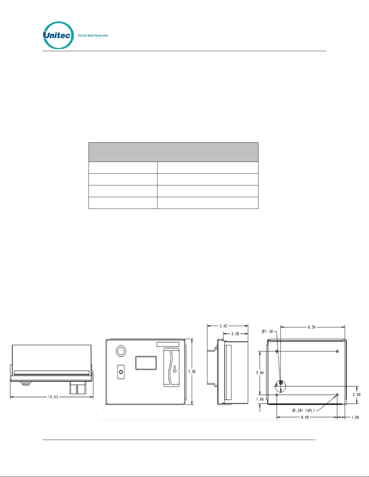
Card Terminal Specifications
Dimensions 10.63” W x 7.56” H x 3.28” D
Weight (approximate) 11 lbs
Power 24VAC, 60Hz
Enclosure Stainless Steel
1 Installation of Card Terminal Box
Follow these steps to install the WashPay Card Terminal:
1. Disconnect all power routing to existing equipment.
2. Using the Card Terminal dimensions shown in
the Card Terminal. Make sure the mounting location is a solid sur face
3. Mount the Card Terminal by either attaching it to the wall surface or recess-mounting
it into a pre-cut hole (determined by the dimensions in
4. Run the timer, coin input/output, and 24VAC wires from the exist ing coin met er box to
the card terminal.
Figure 1, determine where to mount
Figure 1).
Figure 1. WashPay Card Terminal Dimensions
Document Number: WP1004 1 Document Title: WashPay Card Terminal Retrofit Installation Instructions
Page 2
WASHPAY
2 Wiring Connections
Important:
Follow local electrical codes!
Equipment Needed:
• Small Screwdriver
• Wire cutters and strippers
• 22AWG wire.
• Wire Nuts or electrical tape,
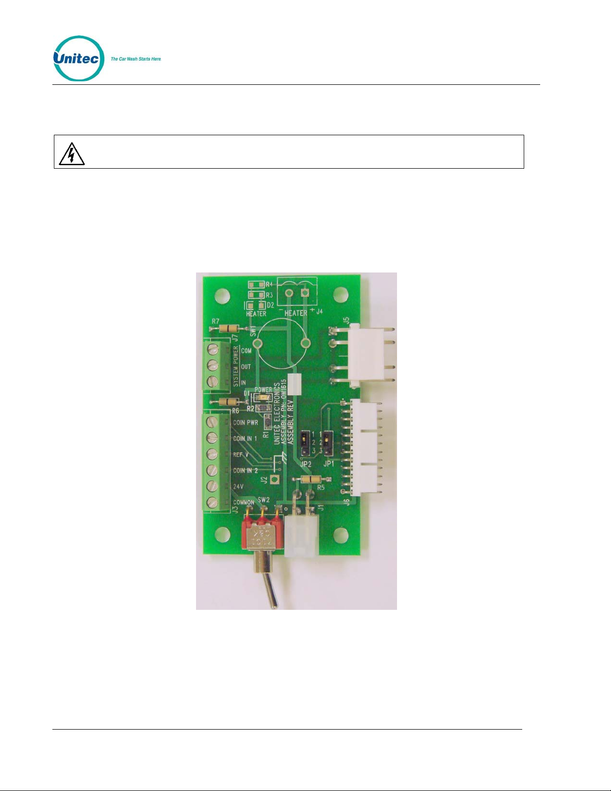
Figure 2. Power Distribution Board
Document Number: WP1004 2
Document Title: WashPay Card Terminal Retrofit Installation Instructions
Page 3

WASHPAY
Figure 3. Rev C Power Board Pin-Out Confi guration
Table 1. Jumper Settings
Jumper Settings
Jumper 1 Reference
1-2 Voltage set by Jumper 2
2-3 24 VAC
Jumper 2 Reference
1-2 +5 VDC
2-3 +12 VDC
None +24 VDC
Table 2. Three-Pin and Six-Pin Terminal Block Wiring for Card Term inal
3-Pin Terminal Strip
Pin Function
1 System Power Com
2 System Power Out
3 System Power In
6-Pin Terminal Strip
Pin Function
1 Coin Acceptor Power
2 Coin Input 1
3 Reference Voltage
4 Coin Input 2
5 24VAC Input Hot
6 24VAC Input Common
Document Number: WP1004 3
Document Title: WashPay Card Terminal Retrofit Installation Instructions
Page 4

WASHPAY
Document Number: WP1004 4
Document Title: WashPay Card Terminal Retrofit Installation Instructions
Page 5

WASHPAY
2.1 Connecting to a Dixmor Timer
1. Remove power from the card terminal by moving the Power Switch to the right po sition.
2. Remove power from the meter box. This may require throwing the breaker in the equipment
room.
3. Set the JP1 Jumper to the 1-2 position.
4. Set the JP2 Jumper to the 2-3 position.
5. Locate the Brown wire on the Dixmor Timer cable harness.
6. Trace the wire in order to find the coin acceptor out put wire. The colors of the wire on the coin
acceptor harness will vary depending on the manufacturer and model be ing used.
7. Run a wire from the coin acceptor output to the Coin Input 1 on the Power Distributin Board
in the card terminal. Coin Input 1 is pin 2 on the 6-Pin Terminal S trip.
8. Pull a CAT5E cable from the patch panel in the office/equipment room to the Card Terminal,
using a ¾” to 1” metal conduit. The CAT5 cable should not exceed 300 feet in length.
9. Assemble the Tool-less RJ-45 connector onto the end of the CAT5 cable. Make sure to use
the “B” pin-out configuration and that it matches the pin-out configuration of the other end of
the CAT5 cable that is plugged into the patch panel.
10. Plug the existing RJ-45 plug inside the Card Terminal into the Tool-less RJ-45 conn ector.
11. Apply power to the Card Terminal and meter box and test.
2.2 Connecting to an IDX Timer
Background:
Typically an IDX timer will have a coin input circuit that is referenced to +5VDC. This can be confirmed by
connecting a multi-meter between the coin input wire and ground. You should measure somewhere
around 5VDC. When a coin is deposited in the coin acceptor, t he coin input of the IDX timer will be pulle d
down to ground (0 VDC) for a short period of time. The coin acceptor will then release the coin input and
it will return to 5VDC.
In order to connect the card terminal in parallel with the IDX timer, we must set it up so its coin input
is also referenced to 5VDC. JP1 and JP2, inside the card terminal, are used to set the reference
voltage to one of four voltages. To set the reference voltage to 5VDC, move jumpers JP1 and JP2
to the 1-2 position.
After setting the reference voltage to 5VDC, you only need to connect the coin input from the IDX
timer to the Coin Pulse In shown in the above drawing.
Procedure:
1. Remove power from the card terminal by moving the Power Switch to the right position.
2. Remove power from the meter box. This may re quire throwing the breaker in the equipment
room.
3. Set the JP1 Jumper to the 1-2 position.
4. Set the JP2 Jumper to the 2-3 position.
Document Number: WP1004 5
Document Title: WashPay Card Terminal Retrofit Installation Instructions
Page 6

WASHPAY
5. Locate the Coin Input wire from the IDX timer.
6. Trace the wire in order to find where it connects to the coin acceptor output.
7. Run a wire from this junction to the COIN IN 1 position on the distribution board inside the
card terminal box.
8. Connect 24VAC o the 24VAC Hot and 24VAC Common positions onhte distribution board.
9. Connect a wire to from the 24VAC Load on the distribution board to the 24 VAC Load on the
IDX Timer. This wire should also the the wiper position of the rotary switch.
10. Apply power to the Card Terminal and meter box and test.
Note: The coin acceptor power connection is option al.
Please refer to the Documents and Downloads tab at www.StartwithUnitec.com for these
additional documents:
WashPay Site Server Installation Manual
WashPay Owners Manual
Sierra Management Application Programming Manual
Document Number: WP1004 6
Document Title: WashPay Card Terminal Retrofit Installation Instructions
 Loading...