

Page 1
Sierra Site Controller Installation Manual
Unitec
www.StartwithUnitec.com
Page 2

WASHPAY
SIERRA SITE CONTROLLER
INSTALLATION MANUAL
Revision D
This manual provides comprehensive installation procedures for the WashPay system.
It includes the process of site planning, site preparation, the mechanical installation of
the WashPay system and the electrical wiring of the unit.
If further assistance is needed, please contact the distributor from which the WashPay
system was purchased.
When calling for assistance, you must have the following information available:
Site Controller Serial Number: ____________
Distributor Name:
DECLARATION OF COMPLIANCE
This equipment has been tested and found to comply with the limits for a Class A
digital device, pursuant to Part 15 of the FCC Rules. These limits are designed to
provide reasonable protection against harmful interference when the equipment is
operated in a commercial environment. This equipment generates, uses, and can
radiate radio frequency energy and, if not installed and used in accordance with the
instruction manual, may cause harmful interference to radio communications.
Operation of this equipment in a residential area is likely to cause harmful interference
in which case the user will be required to correct the interference at his own expense.
COPYRIGHT
© 2012 Unitec, Incorporated. All rights reserved. No part of this book, including text,
screen examples, diagrams, or icons, may be reproduced or transmitted in any form,
by any means (electronic, photocopying, recording, or otherwise) without prior written
permission of Unitec, Incorporated.
TRADEMARKS
WashPay, Unitec, and the Unitec Logo are trademarks, service marks, or registered
trademarks of Unitec, Incorporated.
All other products, services, and company names are trademarks or registered
trademarks of their respective owners.
Document Number: WP1001
Document Name: WashPay Site Controller Installation Manual
Page 3

WASHPAY
Table of Contents
1 Introduction.....................................................................................................................................1
2 Site Planning...................................................................................................................................2
2.1 Conduit Run Considerations..................................................................................................2
3 Installation.......................................................................................................................................3
3.1 Installing the Site Controller...................................................................................................3
3.2 Installing the NEMA Enclosure..............................................................................................4
3.3 Router....................................................................................................................................5
3.4 Dial-up Credit Modem (Optional)...........................................................................................5
Appendix A. Installing the Print Controller.....................................................................................7
Document Name: WashPay Site Controller Installation Manual i
Document Number: WP1001
Page 4

WASHPAY
Index of Figures
Figure 1. WashPay System Overview ....................................................................................................................................1
Figure 2. WashPay Site Controller Computer.........................................................................................................................3
Figure 3. NEMA Enclosure Dimensions..................................................................................................................................4
Figure 4. NEMA Enclosure with Installed Components..........................................................................................................5
Document Number: WP1001 ii
Document Name: WashPay Site Controller Installation Manual
Page 5

WASHPAY
1 Introduction
The WashPay Site Management System is a highly configurable management system
for multi-bay self-serve carwashes. The WashPay system consists of the following
components:
• WashPay-equipped meter box: Meter boxes equipped for Washpay will use
a Unitec timer module and include a waterproof, swipe-style card reader .
• Sierra Site Controller: The Site Controller should be installed in an office
type area. The area should be dry and located away from the car wash
chemicals. If an office area is not available, the Site Controller can be located
in the equipment room. If this is the case, it is recommended that the optional
NEMA enclosure be used in these locations. The NEMA enclosure may be
bolted to the wall in the equipment room.
• Receipt Printer: The optional WashPay Receipt Printer will be mounted in a
pre-cut hole and should be centrally located and visible from all wash bays.
Since the printer is operator-accessible from the rear, the ideal location would
be in the vicinity of the bill changer.
Figure 1. WashPay System Overvie w
Document Name: WashPay Site Controller Installation Manual 1
Document Number: WP1001
Page 6

WASHPAY
2 Site Planning
Sierra Site Controller – The Site Controller will require a minimum of two 115VAC
outlets to power the computer and router. Additional outlets will be required if the
optional Network Kit and LCD monitor are purchased. A CAT5E cable will be needed
to connect the Site Controller to the router.
Receipt Printer – The Receipt Printer will require a 115VAC outlet. A CAT5E cable wil l
need to run between the Receipt Printer and the 16-port switch (optional).
Meter Box - A CAT5E cable will need to run from the meter box to the site Controller
Each run of CAT5E cable cannot exceed 300 feet.
Warning:
Do not run communication wiring in the same conduit as the AC Power wiring.
2.1 Conduit Run Considerations
The WashPay Card Terminal has one cable entrance port located on the b ack on the
bottom right side of the unit. When installing the conduit, po sition the ends of the run so
that they will be easy to line up with these cable entrance ports.
Note:
You will need at least two separate conduit runs, one ¾” diameter con duit for the AC
power, coin input and timer wiring from the existing coin meter box, and one ¾”-1”
diameter conduit for the CAT5 Ethernet cable from the pat ch panel in the equ ipment
room/office. AC power lines must have a dedicated conduit run to avoid
communication errors.
The WashPay Receipt Printer requires one ¾” diameter conduit f or the DC power, and
one ¾“ – 1” diameter conduit for the CAT5 Ethernet cable f rom the patch pan el in the
equipment room/office.
Never run cabling to a WashPay compon ent outside of a conduit.
Document Name: WashPay Site Controller Installation Manual 2
Document Number: WP1001
Page 7

WASHPAY
3 Installation
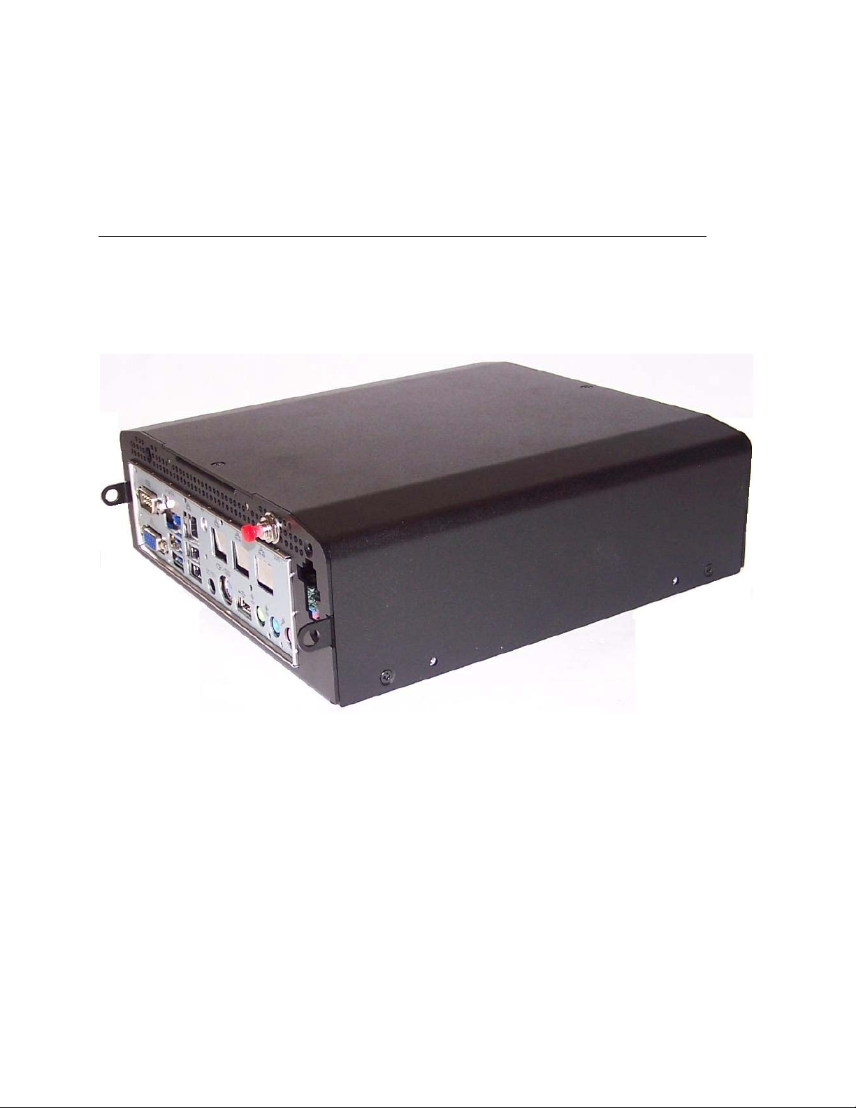
3.1 Installing the Sierra Site Controller
The Sierra Site Controller system consists of a computer, a router, an optional 16-port
switch, and an optional report printer. If credit processing will be done using telephone
lines, an optional credit modem can also be purchased. If the Internet will be used for
credit processing, then the Internet cable can be connected directly to the router and a
credit modem will not be necessary. The computer and switch will connect into the
router using a CAT5E Ethernet cable.
Figure 2. Sierra Site Controller Computer
To install the Site Controller in an office area:
1. Place the Site Controller on a flat surf ace, such as a desk or ta ble.
2. Connect the CAT5 cable from a LAN port of the router to the site controller.
3. Connect the power supply cable to the power supply port.
4. If applicable, connect the monitor to the monitor port, the keyboard to the PS2 port,
and a USB mouse to the USB mouse port.
5. If applicable, connect the modem to the DB9 port.
6. Turn on the power with the red button and program the Site Controller as instructed
in the Sierra Management Application Programming Manual
Document Name: WashPay Site Controller Installation Manual 3
Document Number: WP1001
Page 8

WASHPAY
3.2 Installing the NEMA Enclosure
If an office area is not available, the Site Controller can be located in the equipment
room. If this is the case, it is recommended that the optional NEMA enclosure be used
in this type of location. The NEMA enclosure may be bolted to the wall in the
equipment room. The NEMA enclosure is shipped with a mounting plate for the Site
Controller
Figure 3. NEMA Enclosure Dimensions
Table 1. NEMA Enclosure Specifications
NEMA Enclosure Specifications
Dimensions ” 13.60W x 15.36” H x 7.95” D
Weight (includes NEMA box,
mounting plate, and Site
Controller)
Power 115VAC, 60Hz
Enclosure Polycarbonate
1. Using the dimensions shown in Figure 3, determine where to mount the NEMA
enclosure. Make sure the mounting location is a solid surface.
2. Plan cabling to the NEMA box and drill holes with a hole saw in the bottom of the NEMA
enclosure to route the cabling to the Site Controller .
Document Number: WP1001 4
Document Name: WashPay Site Controller Installation Manual
11.85 lbs
Page 9

WASHPAY
3. Mount the NEMA enclosure by bolting it to the wall surface using the included plastic
brackets.
4. Install the Site Controller by fitting the screws on the mounting plate in the N EMA box into
the slots on the rails mounted on the sides of the Site Controller, so that the ports are
installed parallel to the floor. Slide the Site Controller down and tighten the screws to
secure it.
5. Connect the power supply cable and the CAT5 cable. Connect the modem, if applicab le.
NOTE: DO NOT install the power supply inside the NEMA box.
Figure 4. NEMA Enclosure with Installed Components
3.3 Router
The router provides network connections for each of the devices to the Site Controller.
Unitec provides and supports a four-port router. If you require additional ports, you will
need to purchase the 16-port Ethernet switch option and use it to expand the network.
The router will fit in the NEMA box, if necessary. When troubleshooting the router, refer
to the documentation received with the router. For information on configuring the
router, see the Unitec Router Configuration Guide.
3.4 Dial-up Credit Modem (Optional)
If you use dial-up credit, you will need to purchase the IPTran credit modem option.
The modem is connected to the Site Controller. The phone line connection is provided
via a RJ-11 jack on the modem. Each modem is pre-programmed with the merchant
Document Number: WP1001 5
Document Name: WashPay Site Controller Installation Manual
Page 10

WASHPAY
account information before it is shipped. You must have your merchant account set up
in advance for this to be done.
Document Number: WP1001 6
Document Name: WashPay Site Controller Installation Manual
Page 11

WASHPAY
Appendix A. Installing the Print Controller
The print controller option allows you to print reports from the WashPay to a printer
connected to the local area network (LAN). The print controller is pre-configured at
Unitec.
3.4.1.1 Installation Procedures
1. Connect the USB cable from the printer to the USB port on the pr int controller.
2. Connect one end of the Ethernet patch cable to the Ethernet port on the print
3. Connect the other end of the Ethernet patch cable t o the router.
4. Connect the AC adapter to the print controller and plug it in.
Note:
Note:
controller.
You must purchase the USB print cable separately.
Unitec has tested these printers with the print controller and can verify that they will
work without any additional setup procedures. If you wish to use a different printer,
make sure that it is compatible with the printer driver HP PCL5 or greater.
Document Number: WP1001 7
Document Name: WashPay Site Controller Installation Manual
 Loading...