

Page 1

ReachFree ID
Installation Instructions
For Portal, Sentinel and C-Start
Unitec
www.StartwithUnitec.com
Page 2

R E A C H F R E E I D
[ T H I S P A G E I N T E N T I O N A L L Y L E F T B L A N K ]
Document Number: RFID1001 ii
Document Name: Unitec RFID Field Retrofit Installation Guide
Page 3

R E A C H F R E E I D
Table of Contents
Introduction .............................................................................................................. 1
Software Requirements ........................................................................................... 1
Site Planning ............................................................................................................ 1
Parts Checklist ......................................................................................................... 1
Installation Procedures ............................................................................................ 2
Install the Mounting Pole (Optional) ...................................................................... 2
Install the Reader .................................................................................................. 4
Site Installation...................................................................................................... 6
Connector Wiring .................................................................................................. 8
Mount RFID Board and Connect Cables ............................................................... 9
Portal TI Installation ......................................................................................... 9
Sentinel and C-Start Installation .................................................................... 12
RFID Tags ............................................................................................................... 14
Program the Unitec Entry Unit .............................................................................. 14
Troubleshooting ..................................................................................................... 15
Document Number: RFID1001 iii
Document Name: Unitec RFID Field Retrofit Installation Guide
Page 4

R E A C H F R E E I D
Table of Figures
Figure 1. RFID Mounting Post ...............................................................................2
Figure 2. RFID Post Flange ...................................................................................3
Figure 3. AWID Reader Dimensions .....................................................................4
Figure 4. Reader with Mounting Assembly ............................................................5
Figure 5. RFID Reader Installation - Front View ....................................................6
Figure 6. RFID Reader Installation - Top View ......................................................7
Figure 7. Wired Connector ....................................................................................8
Figure 8. RFID Board Location in Portal with Coin/Bill Dispensing .......................9
Figure 9. RFID Board Location in Cashless Portal ................................................9
Figure 10. RFID Board Connections for Portal .................................................... 11
Figure 11. RFID Board Location in Sentinel ........................................................ 12
Figure 12. RFID Board Connections for Sentinel and C-Start ............................. 13
Figure 13. Sample RFID Tag .............................................................................. 14
Figure 14. RFID Troubleshooting Screen ............................................................ 15
Figure 15. RFID Settings Screen ........................................................................ 16
Document Number: RFID1001 iv
Document Name: Unitec RFID Field Retrofit Installation Guide
Page 5

R E A C H F R E E I D
Introduction
The ReachFree ID product is a house account application designed to build car wash volume and
increase throughput with secure, subscription-based wash accounts. The RFID reader reads the
RFID tag that is adhered to the account holder’s windshield.
If the account is valid, the Unitec entry unit will approve the transaction without any interaction from
the account holder and will allow the vehicle to proceed past the entry system and into the tunnel or
in-bay automatic.
Software Requirements
In order for the ReachFree ID system to function properly, the Unitec entry unit must be updated to
the most recent version of software.
Site Planning
If this is a new installation, a conduit will need to be run from the Unitec entry unit to the mounting
surface for the reader.
The reader may be mounted on any material including metal, but there must be open space in front
of the reader and to its sides. There must be no material interfering with the reader’s surveillance
zone between the reader and the tags’ location.
If using the optional mounting pole, the reader should be mounted beside the far side of the Unitec
entry unit (with the flange flush against the base, as shown in Figure 5) because the proximity
sensor on the unit door can be setup to activate the reader. The reader should be mounted on a
pole 7 feet above the vehicle lane.
Parts Checklist
Prior to retrofitting an existing Unitec entry unit, verify that you have all parts required:
AWID RFID Reader with cable (SA2135)
RFID Cover (MF1584) and Reader pole-mounting bracket (OM1673)
Power Supply (PS2018)
30 ft data cable (CA2179)
RFID Board (OM1528) mounted on bracket (MF1583) with 2 6-32 nuts
I2C Cable
50 RFID tags (OM1672) (Please note: tag refills come in groups of 50)
8ft Mounting Pole (MF1589) (Optional)
3/8” concrete bolts (Optional)
Drill with concrete bit (not included)
Document Number: RFID1001 1
Document Name: Unitec RFID Field Retrofit Installation Guide
Page 6

R E A C H F R E E I D
Installation Procedures
Install the Mounting Pole (Optional)
The RFID kit comes with an 8 foot mounting post with a mounting flange at the base, as an option.
It’s designed to accommodate both surface-mounted above ground conduit for existing installations
and underground conduit for new construction. For surface run conduit, there’s a threaded boss
welded to the post on the bottom flange. It accommodates a ½” conduit fitting to run liquid-tight
conduit to the post. The conduit is then secured by screwing the conduit fitting into the boss. For
underground conduit, the installer should run the conduit up the center of the post. There is a hole
near the top of the post where the cable will exit to connect with the RF reader.
Figure 1. RFID Mounting Post
Document Number: RFID1001 2
Document Name: Unitec RFID Field Retrofit Installation Guide
Page 7
R E A C H F R E E I D
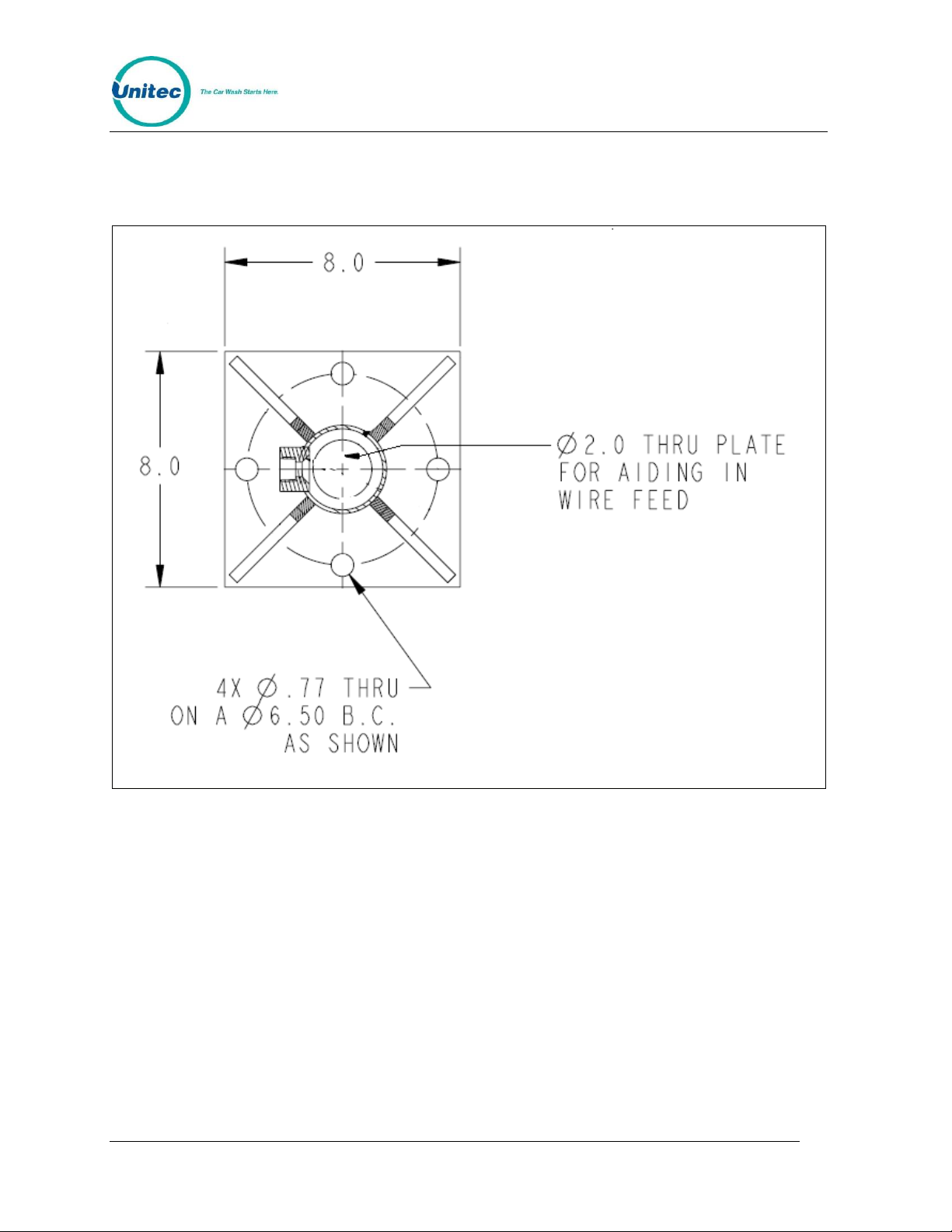
To mount the post, the installer will need to drill (4) holes and use concrete anchor bolts to secure
the flange to the concrete, as shown below. The flange should be flush to the side of the entry unit,
as shown in Figure 5.
Figure 2. RFID Post Flange
Document Number: RFID1001 3
Document Name: Unitec RFID Field Retrofit Installation Guide
Page 8

R E A C H F R E E I D
Install the Reader
Note: Keep the reader assembled. Do not remove the aluminum plate behind the reader.
Do not remove the plastic cover of the reader. Do not tighten or loosen the screws through
the cover.
Figure 3. AWID Reader Dimensions
Document Number: RFID1001 4
Document Name: Unitec RFID Field Retrofit Installation Guide
Page 9

R E A C H F R E E I D
Figure 4. Reader with Mounting Assembly
1. Attach the mounting assembly to the reader’s metal plate using 1/4”-20 screws, if
needed for your installation.
2. If you are mounting the reader to a pole, leave the mounting assembly fully
assembled and use the supplied metal ties to secure the reader to the pole
approximately 7 feet above the lane.
Note: If you are mounting the reader on to something other than a pole, you will need
to order another style of mount.
Document Number: RFID1001 5
Document Name: Unitec RFID Field Retrofit Installation Guide
Page 10

R E A C H F R E E I D
Site Installation
Figure 5. RFID Reader Installation - Front View
3. Aim the reader so that center front face of the reader points toward a spot on the
vehicle lane approximately 18” from the middle front of the entry unit. This usually
requires that the reader be adjustable downward about 45 to 90 degrees (“tilt”),
and slightly toward the approaching vehicles (“pan”).
Document Number: RFID1001 6
Document Name: Unitec RFID Field Retrofit Installation Guide
Page 11

R E A C H F R E E I D
Figure 6. RFID Reader Installation - Top View
Document Number: RFID1001 7
Document Name: Unitec RFID Field Retrofit Installation Guide
Page 12

R E A C H F R E E I D
Connector Wiring
Figure 7. Wired Connector
Document Number: RFID1001 8
Document Name: Unitec RFID Field Retrofit Installation Guide
Page 13

R E A C H F R E E I D
Mount RFID Board and Connect Cables
Portal TI Installation
If installing the board inside a Portal with coin or bill dispensing, the RFID board mounts to the side
of the bill dispenser/coin hopper cage inside the entry unit.
Figure 8. RFID Board Location in Portal with Coin/Bill Dispensing
If installing the board inside a cashless Portal, the RFID board mounts to the top back wall of the
unit to the left of the power supply tower.
Figure 9. RFID Board Location in Cashless Portal
Document Number: RFID1001 9
Document Name: Unitec RFID Field Retrofit Installation Guide
Page 14

R E A C H F R E E I D
1. Run the data cable down thru the unit’s conduit and up to the mounted reader.
2. Plug the female end of the in-line connector on the 30’ data cable into the male end
of the in-line connector on the reader. To ensure a tight, water-proof connection, fit
the two ends together, press firmly and turn the ends to lock them together.
3. Connect the other end of the data cable with the 6-pin Phoenix connector to the J2
connector on the RFID board
4. Plug the power supply into the J1 power connector on the RFID board and the
power supply cord into an outlet on the power supply panel at the back of the unit.
5. Connect the 4-pin I2C cable to the J3 4-pin connector on the RFID board. Connect
the other 4-pin connector to the CN3 connector at the bottom of the carrier board on
the right wall of the unit.
Document Number: RFID1001 10
Document Name: Unitec RFID Field Retrofit Installation Guide
Page 15

R E A C H F R E E I D
Figure 10. RFID Board Connections for Portal
Document Number: RFID1001 11
Document Name: Unitec RFID Field Retrofit Installation Guide
Page 16

R E A C H F R E E I D
Sentinel and C-Start Installation
If installing the board inside a Sentinel or C-Start unit, the RFID board mounts to the right inside
wall of the electronics side of the unit.
Note: The RFID board should be mounted upside down on the mounting plate so that the
diagnostic LEDs are facing the door of the unit.
Figure 11. RFID Board Location in Sentinel
1. Run the data cable down thru the unit’s conduit and up to the mounted reader.
2. Plug the female end of the in-line connector on the 30’ data cable into the male end
of the in-line connector on the reader. To ensure a tight, water-proof connection, fit
the two ends together, press firmly and turn the ends to lock them together.
3. Connect the other end of the data cable with the 6-pin Phoenix connector to the J2
connector on the RFID board
4. Plug the power supply into the J1 power connector on the RFID board and the
power supply cord into an outlet on the power supply panel at the back of the unit.
5. Connect the 4-pin I2C cable to the J3 4-pin connector on the RFID board. Connect
the other 5-pin end to a 5-pin connector on the CPU module on the left side of the
case.
Document Number: RFID1001 12
Document Name: Unitec RFID Field Retrofit Installation Guide
Page 17

R E A C H F R E E I D
Figure 12. RFID Board Connections for Sentinel and C-Start
Document Number: RFID1001 13
Document Name: Unitec RFID Field Retrofit Installation Guide
Page 18

R E A C H F R E E I D
RFID Tags
Figure 13. Sample RFID Tag
The ReachFree ID vehicle tag should be applied to the INSIDE bottom or top corner of the
windshield on the driver’s side, depending on the height of the vehicle, so that the tag is in
approximately the same place on every vehicle. For example, if the vehicle is a taller SVU,
apply the tag to the bottom of the windshield. If the vehicle is a smaller sports car, apply the tag
to the top corner of the windshield. Make sure the windshield is clean before adhering the tag
to the glass.
Program the Unitec Entry Unit
The ReachFree ID system is based off a subscription-based house account. You will need to
set up a house account program and account for each vehicle tag. For more information, see
the Sierra Management Application Programming Manual, which is available on our website at
http://www.StartwithUnitec.com/.
The RFID reader’s default setting is set to “Always On.” If you wish to change it so that the
reader is triggered to turn on by the proximity sensor in the entry unit, you must configure the
RFID reader in the Device Profiles tab.
Document Number: RFID1001 14
Document Name: Unitec RFID Field Retrofit Installation Guide
Page 19

R E A C H F R E E I D
Troubleshooting
Figure 14. RFID Troubleshooting Screen
Login to Maintenance Mode>Test Hardware>RFID Reader to make sure the ReachFree ID
system is reading the tags properly. Once the vehicle tag is detected by the reader, the 8-digit
code will be displayed in the text box on the screen. As long as the RF tag remains in range of
the reader, the entry unit will beep once per second. You can determine the area the RF
Reader can read tags by moving the tag around and listening for the beeps. As long as the unit
is beeping once per second, the RF tag is in-range.
Document Number: RFID1001 15
Document Name: Unitec RFID Field Retrofit Installation Guide
Page 20

R E A C H F R E E I D
To adjust the power or threshold (read rate) of the reader, press Adjust Antenna.
Figure 15. RFID Settings Screen
The power level and threshold may be adjusted from 1-7 with 7 being the highest. The
threshold (or read rate) reads at a multiple of 6 per second. For example, if the threshold is set
to 4, the read rate is 24 tag reads per second.
These settings are also available on the pots on the RFID board.
NOTE: The software settings override the pot setting on the board.
The top pot on the Portal RFID board (bottom pot on Sentinel) controls the power output on the
reader.. If you need to adjust the power for the reader on the board, insert a small flat head
screwdriver in top pot in the slot facing out toward the door of the unit and turn it counter-clockwise
to reduce the power output. The power levels range from 1 to 7, with 7 being the highest. Since the
pot and power level numbers are very small, the top 3 LEDS will also light up in the corresponding
sequence listed in the following table:
Document Number: RFID1001 16
Document Name: Unitec RFID Field Retrofit Installation Guide
Page 21

R E A C H F R E E I D
LEDs
Power Level
No LEDs lit
0
1 Green LED middle LED)
1
1 Yellow LED
2
1 Green LED + 1 Yellow LED
3
1 Red LED
4
1 Green LED + 1 Red LED
5
1 Yellow LED + 1 Red LED
6
1 Green LED + 1 Yellow LED + 1 Red LED
7
LEDs
Read Rate per Second (x6)
No LEDs lit
0
1 Green LED middle LED)
1
1 Yellow LED
2
1 Green LED + 1 Yellow LED
3
1 Red LED
4
1 Green LED + 1 Red LED
5
1 Yellow LED + 1 Red LED
6
1 Green LED + 1 Yellow LED + 1 Red LED
7
The bottom pot on the Portal RFID board (top pot on the Sentinel) controls the threshold (rate of
tag reads per second). If you need to adjust the threshold for the reader, insert a small flat head
screwdriver in pot in the slot facing out toward the door of the unit and turn it to adjust the threshold.
The levels range from 1 to 7, with 7 being the highest. Since the pot and power level numbers are
very small, the top 3 LEDS will also light up in the corresponding sequence listed in the table below:
Document Number: RFID1001 17
Document Name: Unitec RFID Field Retrofit Installation Guide
Page 22

R E A C H F R E E I D
LED
Label
Color
Light Status
Description
LED 1
Serial
Red
Blinks during
data transfer
Indicates when the RF Reader sends data to
the RFID board. Most of the time this will be
when the RF Reader senses a RF tag.
LED 2
I2C
Yellow
Blinks during
data transfer
Indicates when the RFID board sends and
receives data to and from the entry unit
LED 3
Ant On
Green
Solid
Indicates when the reader is enabled. If the
reader is enabled by the proximity sensor, then
this LED will be OFF most of the time. If the
reader is always enabled then this LED will be
constantly lit.
LED 4
Status
Green
Blinking
Blinks once per second to show that the RFID
board is alive
LED 5
Power
Green
Solid
Indicates power to the board
LEDS
The RFID board has 5 LEDs that indicate whether or not the RFID system is working. The table
below defines each LED and its function.
Tips and Suggestions
The ReachFree ID reader uses the 900 MHz frequency which can cause interference with
other electronic devices that use the 900 MHz frequency range. Unitec strongly suggests you
observe the following warnings:
Stay away from UHF communications devices.
Avoid arc lighting fixtures by 3 or 4 feet.
Keep neighboring long-range readers on parallel lanes at least 12 feet apart, with
their surveillance zones parallel to each other.
Do not have identical readers facing each other (but “back-to-back” is OK).
Document Number: RFID1001 18
Document Name: Unitec RFID Field Retrofit Installation Guide
 Loading...