

Page 1
Portal TI Console
Installation & Operations Manual
Unitec
443-561-1200 • www.StartwithUnitec.com
Page 2

PORTAL TI
PORTAL TI CONSOLE INSTALLTION AND
OPERATIONS MANUAL
SOFTWARE VERSION 2.0.0.1
In this manual, we discuss in detail the components and operations of the Portal TI Console.
If further assistance is needed, please contact the distributor from which the Portal TI
Console was purchased.
When calling for assistance, you must have the following information available:
Portal TI Console Serial Number:
Distributor Name:
COPYRIGHT
© 2012 Unitec, Incorporated. All rights reserved. No part of this book, including text, screen
examples, diagrams, or icons, may be reproduced or transmitted in any form, by any means
(electronic, photocopying, recording, or otherwise) without prior written permission of Unitec,
Incorporated.
TRADEMARKS
Portal TI, Wash Select II, Unitec, and the Unitec Logo are trademarks, service marks, or
registered trademarks of Unitec, Incorporated.
All other products, services, and company names are trademarks or registered trademarks of
their respective owners.
DECLARATION OF COMPLIANCE
This equipment has been tested and found to comply with the limits for a Class A digital
device, pursuant to Part 15 of the FCC Rules. These limits are designed to provide
reasonable protection against harmful interference when the equipment is operated in a
commercial environment. This equipment generates, uses, and can radiate radio frequency
energy and, if not installed and used in accordance with the instruction manual, may cause
harmful interference to radio communications. Operation of this equipment in a residential
area is likely to cause harmful interference in which case the user will be required to correct
the interference at his own expense
Document Number: PTL1005 ii
Document Title: Portal TI Console Installation and Operations Manual
.
Page 3

PORTAL TI
Table of Contents
1 Controller Console Overview........................................................................................................1
1.1 Introduction................................................................................................................................1
1.2 Consol e Hardware Overview.....................................................................................................1
2 Console Hardware Installation Procedures.................................................................................2
2.1 Requirements.............................................................................................................................2
2.2 Installation Procedures...............................................................................................................2
2.2.1 Console Installation Procedure ....................................................................................................2
2.2.2 Printer Installation Procedure.......................................................................................................3
2.2.3 Card Reader Installation Procedure.............................................................................................3
2.2.4 Keyboard and Mouse Installation Procedures..............................................................................3
3 Console Configuration Procedures..............................................................................................4
3.1 Requirements.............................................................................................................................4
3.2 Console Configuration Procedures............................................................................................4
4 Console Operations .......................................................................................................................9
4.1 Using the Touch-Screen Interface.............................................................................................9
4.2 Daily Operations.......................................................................................................................10
4.3 Console Diagnostics ................................................................................................................11
4.3.1 Calibrate the Touch-Screen.......................................................................................................11
4.3.2 Printer Test.................................................................................................................................12
4.3.3 Card Reader Test.......................................................................................................................13
5 Controller Console Maintenance ................................................................................................14
5.1 Cleaning...................................................................................................................................14
5.2 Verifying Ethernet Communications.........................................................................................14
5.3 Console Power Specifications .................................................................................................14
5.4 Changing the Battery ...............................................................................................................14
Document Number: PTL1005 i
Document Title: Portal TI Console Installation and Operations Manual
Page 4

PORTAL TI
Index of Figures
Figure 1. Console Connection Locations.........................................................................................2
Figure 2. Red Connection Failed Screen......................................................................................... 4
Figure 3. Router Test Successful.....................................................................................................5
Figure 4. Router Test Failed ............................................................................................................6
Figure 5. Console Configuration Screen.......................................................................................... 6
Figure 6. Console Login Screen ......................................................................................................8
Figure 7. Console Sales Screen....................................................................................................10
Figure 8. Check-Void Code Screen...............................................................................................11
Figure 9. Console Calibration Screen............................................................................................12
Figure 10. Console Printer Test Screen.........................................................................................12
Figure 11. Console Card Reader Test Screen...............................................................................13
Figure 12. Lithium Battery Location...............................................................................................15
Document Number: PTL1005 ii
Document Title: Portal TI Console Installation and Operations Manual
Page 5

PORTAL TI
1 Controller Console Overview
1.1 Introduction
The Portal TI Console provides compact local access to the Management Mode of the Portal
TI Software. Unitec designed the console primarily to be used as a Point of Sale (POS) inside
your convenience sore (C-Store) or your site office. In this role, your onsite employees use
the console to sell washes, update House Accounts, and per form shift or d aily closes.
In addition, by connecting the keyboard and mouse, the console functions as a data entry
point. This allows users to enter and edit information in the Portal TI software. For example,
users can enter Vault Events when they add or remove cash from the Vault, or add the
contact details to existing or new House Accounts. Site managers also have the ability to edit
system configuration settings through the Setup menus.
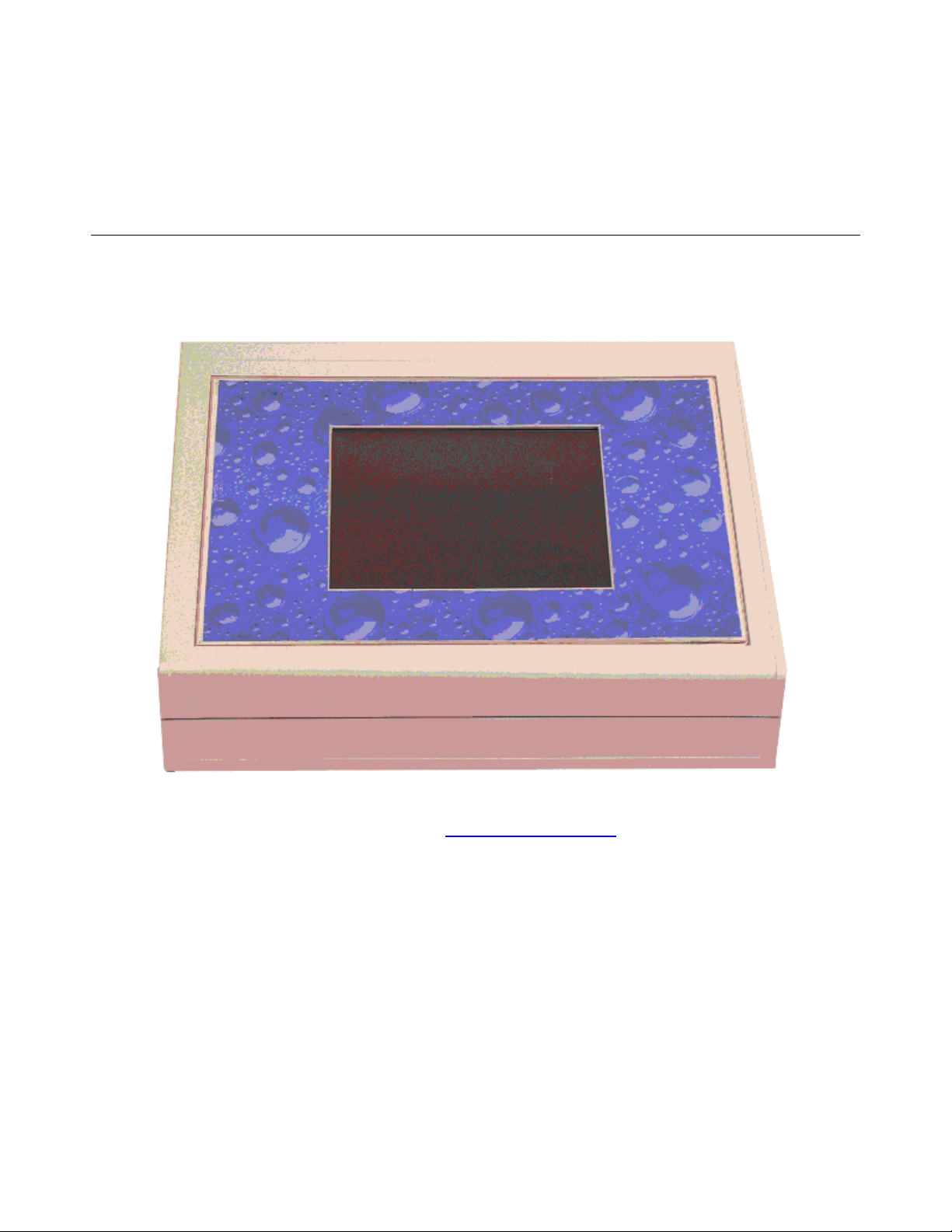
1.2 Console Hardware Overview
The console is a compact case with a touch-screen interface. The mouse, power supply,
printer, and network cables plug into the back of the unit. A keyboard is not needed because
you may use the touch screen on the console to enter all configuration information.
When you purchase the Console option, you will receive the following components:
• Portal TI Console
• Limited Source Power Supply
• Ticket Printer
• Parallel Printer Cable
• Tabletop Magnetic Swipe Reader
• Spare Paper Roll and Ribbon
A USB keyboard and USB mouse can be connected to the USB ports on the back of the
Console.
Document Number: PTL1005 1
Document Title: Portal TI Console Installation and Operations Manual
Page 6
PORTAL TI
2 Console Hardware Installation Procedures
Installation of the Console consists of connecting the Power Supply, the Receipt Printer, the
Card Reader, and then connecting the Console to the network r outer.
2.1 Requirements
The console requires the following items:
• LAN - The Console can only be used if you have the Portal connected to a Local
Area Network (LAN).
• Ethernet Cable – You must have sufficient Ethernet cable to reach from the
Console location to the LAN/Router (this length cannot exceed 294ft).
2.2 Installation Procedures
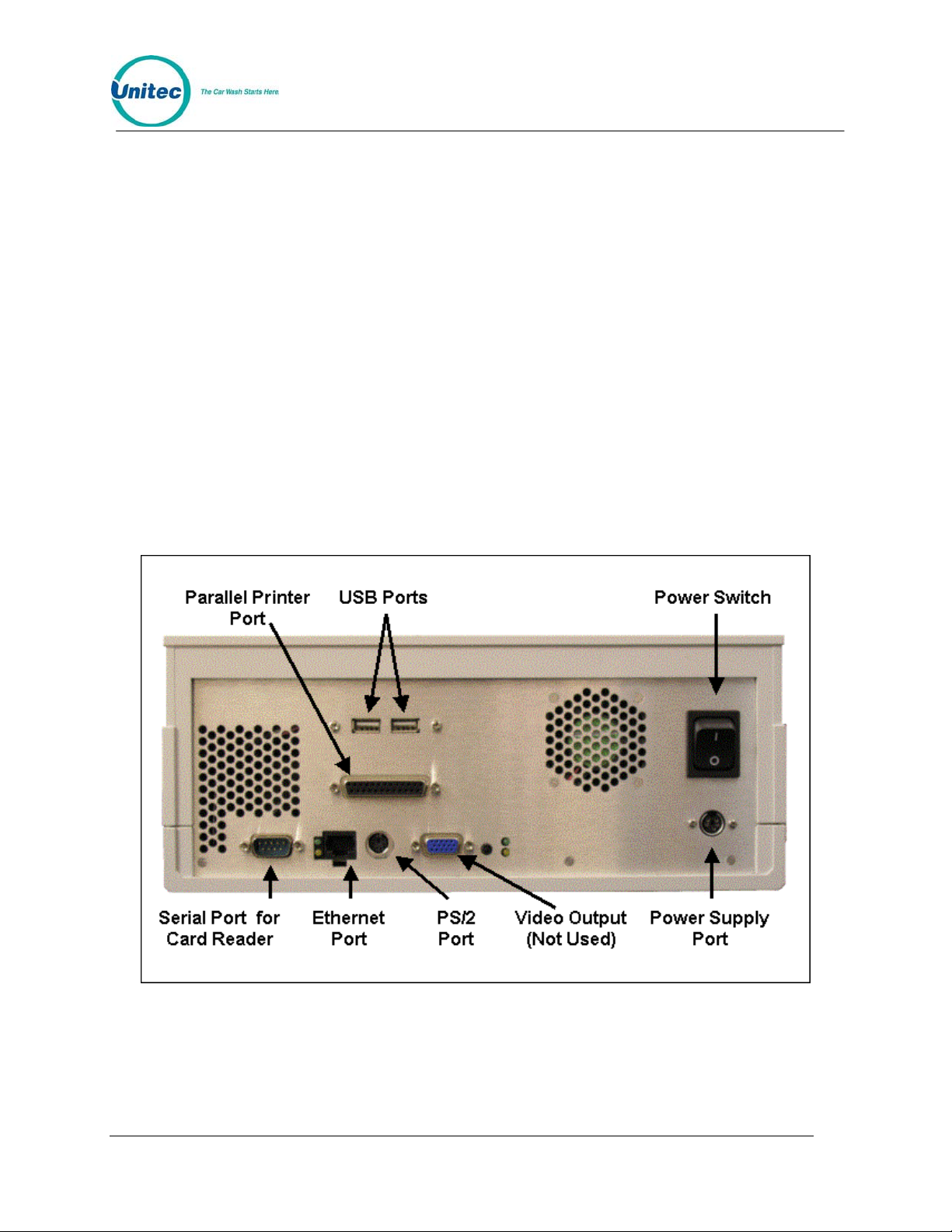
Refer to Figure 1 during installation for identification of the port s on the back panel of the unit.
Figure 1. Console Connection Locations
2.2.1 Console Installation Procedure
1. Connect the Ethernet cable to the Ethernet Port.
Document Number: PTL1005 2
Document Title: Portal TI Console Installation and Operations Manual
Page 7

PORTAL TI
2. Connect the other end of the Ethernet cable to the LAN/Router.
3. Connect the Power Supply to the Power Supply Port.
4. Plug in the power supply.
2.2.2 Printer Installation Procedure
5. Connect the 25-pin connector of the printer cable to the parallel port on the Console;
secure using the side screws.
6. Connect the Centronics connector (other end of the cable) to the wide slot on bottom
of the Receipt Printer; secure using the wire holders on the printer slot.
7. Plug in the Receipt Printer power cable.
2.2.3 Card Reader Installation Procedure
1. Connect the Card Reader serial cable to the Serial Port located on the back of the
Console; secure using the side screws.
2. Verify that the default DIP switch settings are 1, 2 a nd 7 ON, the rest OFF.
2.2.4 Keyboard and Mouse Installation Procedures
The keyboard and trackball mouse can optionally be connected to the Console.
1. Plug the trackball/mouse USB connector into either of the USB ports located on the
back of the Console.
2. Remove the USB to PS/2 Converter from the keyboard, if attached.
3. Plug the keyboard USB connector into the remaining USB port located on the back of
the Console.
Document Number: PTL1005 3
Document Title: Portal TI Console Installation and Operations Manual
Page 8

PORTAL TI
3 Console Configuration Procedures
Now that the Console has been installed, you will need to configure it to communicate with
your Portal TI.
3.1 Requirements
In order to properly configure the Console, you will need the computer name of the Portal TI
Unit. The name is displayed in the Status box on the Porta l Maintenance Screen.
3.2 Console Configuration Procedures
The following procedures should only be performed by qualified IT professio nals.
1. With the Portal TI Unit connected to the network and powered on, power on the
Console.
The first time you boot up the Console after installing new software, the unit will run the
Note:
gray screen program, which performs a series of self-configuration procedures. DO
NOT INTERRUPT THESE PROCEDURES.
2. When the Console completes the boot process (when installing new software only),
the Console will display the following screen:
Figure 2. Red Connection Failed Screen
Document Number: PTL1005 4
Document Title: Portal TI Console Installation and Operations Manual
Page 9

PORTAL TI
3. Press the “Test Connection to Router Button” on the touch-screen to make sure the
console can detect the router.
4. If router is detected, the following screen will appear:
Figure 3. Router Test Successful
5. If the router is not detected, the following screen will appear: Check your router
connections and perform the test again.
Document Number: PTL1005 5
Document Title: Portal TI Console Installation and Operations Manual
Page 10

PORTAL TI
Figure 4. Router Test Failed
6.
Press the Configure button on the touch-screen to display the Console Configuration
screen. You may also press F1 on the keyboard.
Figure 5. Console Configuration Screen
Document Number: PTL1005 6
Document Title: Portal TI Console Installation and Operations Manual
Page 11

7. In the Computer Name field, replace the word PORTAL with the Computer Name of
the Portal.
8. For example, if your Portal TI Computer Name is PORTAL94df4c, the Computer
Name field should read PORTAL94df4c.
9. Click OK to continue.
The Console Configuration screen allows you to configure the fo llowing settings:
Computer Name – The name of the Portal the Console is connected to. If you have more than one
Portal connected to the Router, the codes issued at the Console will only be usable at the Portal
listed in this field. In addition, all sales data pertaining to sales made at the Console will be recorded
in the reports stored on this Portal.
Reset to Sales screen after Timeout – This checkbox determines the screen that will be displayed
when the Console times out. Check this box to return to the Sales screen at timeout. Leave this box
unchecked to return to the Management screen at timeout.
Timeout Value in Seconds – This value determines how many seconds the Console will wait for
input during a transaction before returning to either the Sales screen or the Management screen
(depending on the Reset configuration setting selected ab ove).
PORTAL TI
Set Clock – Click this button to set the clock on the Console.
If the Console cannot establish communications with the Portal, the red screen will re-
Note:
When it has completed connecting to the Portal TI unit, the following screen will appear:
appear. Verify the Computer Name settings and click Retry. If there are still no
communications, contact Unitec for additional su pport.
Document Number: PTL1005 7
Document Title: Portal TI Console Installation and Operations Manual
Page 12

PORTAL TI
Figure 6. Console Login Screen
Document Number: PTL1005 8
Document Title: Portal TI Console Installation and Operations Manual
Page 13

PORTAL TI
4 Console Operations
The Portal console is designed to be used as a Point of Sale (POS) system inside the
convenience store or office. The console allows you to sell wash codes, check and void codes
sold from the register and gas pumps and print revenue or sales reports (must have a p rint
server installed).
In order to use the console, you must first configure the Sales screen through the Sierra
Management Application pages. Refer to the Sierra Management Application Programming
Manual on
Once the Sales screen is configured, login to the console using the defau lt administrator
username and password (00/00) then press Enter.
4.1 Using the Touch-Screen Interface
The Console provides a touch-screen interface that was selected to eliminate the need for a
keyboard and mouse at the point of sale. To use the touch scr een interf ace , use a stylus (like
the ones used with personal digital assistants) or the tip of a pen cap to click the buttons on
the screen. Using your finger to select the buttons can lead to inaccurate results. If you must
use your finger, try to use your fingernail alone.
www.StartwithUnitec.com for more detailed instructions.
Document Number: PTL1005 9
Document Title: Portal TI Console Installation and Operations Manual
Page 14

PORTAL TI
4.2 Daily Operations
The previously configured sales screen will be displayed.
Figure 7. Console Sales Screen
From this screen, you simply select the wash package you wish to purchase or the r eport you
wish to print.
Document Number: PTL1005 10
Document Title: Portal TI Console Installation and Operations Manual
Page 15

PORTAL TI
Figure 8. Check-Void Code Screen
To check or void a code, press the appropriate button on the sales screen. Enter the code .
The console will display a message stating whether the code was ei ther valid or invalid, or will
disable the code.
4.3 Console Diagnostics
The console software allows you to configure Console Settings and Touch-Screen
Calibration, and to test the Printer and Card Reader.
In order to access the following screens, you must have the keyboard connected to the
Console.
Note:
4.3.1 Calibrate the Touch-Screen
The Touch-Screen converts taps on the screen to mouse-clicks. Sometimes tapping on the
screen will produce an inaccurate mouse-click. The calibration utility allows you to make the
taps more accurate by recording where the mouse-click is supposed to be in relation to the
touch-screen.
To launch the touch-screen calibration utility, press the F2 key on the keybo ard and follo w the
instructions on the screen.
Document Number: PTL1005 11
Document Title: Portal TI Console Installation and Operations Manual
Page 16

PORTAL TI
Figure 9. Console Calibration Screen
4.3.2 Printer Test
To test the receipt printer, press the F3 key on the keyboard. When you do, you will see the
following screen:
Click the Print button to test the printer.
Figure 10. Console Printer Test Screen
Document Number: PTL1005 12
Document Title: Portal TI Console Installation and Operations Manual
Page 17

PORTAL TI
4.3.3 Card Reader Test
To test the receipt printer, press the F4 key on the keyboard. When you do, you will see the
following screen:
Figure 11. Console Card Reader Test Screen
Swipe a card to see the data being read by the card reader.
Document Number: PTL1005 13
Document Title: Portal TI Console Installation and Operations Manual
Page 18

PORTAL TI
5 Controller Console Maintenance
The C-Store Controller Console is designed to require minimum maintenance.
5.1 Cleaning
Clean the touch screen interface using non-abrasive cleaners. Spray the screen cleaner onto
a soft, lint-free cloth, and then wipe the touch screen. Do not spray any cleaner directly onto
the touch screen.
5.2 Verifying Ethernet Communications
Next to the Ethernet port are two LEDs. When connected, at least one of the LEDs should be
ON. If neither LED is lit, verify that the cable is connected on both ends, and that the network
router is powered on and operating correctly.
5.3 Console Power Specifications
The Console must be powered by the supplied Limited Source Power Supply only.
RATING:
12V 1.5A
3.3V 1.5A
5.4 Changing the Battery
Caution:
The Console electronics include a lithium battery that powers the BIOS memory. In the event
that this battery located inside the Console requires replacement, use only 3V 2032 batteries.
1. Remove the screws located on the bottom of the Console.
2. Carefully lift the top of the Console off the base of the Console. The touch screen
components are plugged into the Console motherboard.
Installing the wrong type of battery creates a risk of explosion. Dispose of used
batteries according to manufacturer’s instructions.
Document Number: PTL1005 14
Document Title: Portal TI Console Installation and Operations Manual
Page 19

PORTAL TI
Figure 12. Lithium Battery Location
3.
Remove and properly dispose of the old battery.
4. Insert the replacement battery.
5. Replace the top of the Console; be careful not to pinch any wires between the cover
and the base.
6. Secure the top of the console to the base using the screws re moved in Step 1.
Document Number: PTL1005 15
Document Title: Portal TI Console Installation and Operations Manual
 Loading...