

Page 1

Or i g i n a l
Op e r a t i n g i n s t r u c t i o n s • In s t r u c c i o n e s d e m a n e j o
M o d e d ‘ e m p l o i
M AB 5 2 5
Page 2

C o n t e n t s Pa g e
Op e r a t i n g i n s t r u c t i o n s . . . . . . . . . . . . . 3 3
In d i c e Pá g i n a
In s t r u c c i o n e s d e m a n e j o . . . . . . . . . . . 9 3
So m m a i r e Pa g e
M o d e d ’ e m p l o i . . . . . . . . . . . . . . . . . . . 6 3
Distributed exclusively by:
2 2 Ha r b o r Av e n u e , No r w a l k , C T 0 6 8 5 0 U SA
T o l l - F r e e : 8 0 0 - 7 0 0 - 5 9 1 9
Ph o n e : 2 0 3 - 8 5 3 - 9 5 2 2
F a x : 2 0 3 - 8 5 3 - 9 9 2 1
Em a i l : i n f o @ c s u n i t e c . c o m
w w w . c s u n i t e c . c o m
BA_MAB525_0310_A3 © 2012 BDS Maschinen GmbH
Page 3

T a b l e o f C o n t e n t s
F o r e w o r d . . . . . . . . . . . . . . . . . . . . . . . . . 4
In s t r u c t i o n s f o r u s e . . . . . . . . . . . . . . . . 4
Copyright .........................4
Structure of the safety warnings ........5
Intended use .......................6
Liability disclaimer ..................6
Sa f e t y . . . . . . . . . . . . . . . . . . . . . . . . . . . . 7
Fundamental safety precautions .......7
Electric shock hazard ................8
Risk of injury .......................9
Prevention of damage ..............10
Safety installations .................11
Personal protective equipment ........12
C o m p o n e n t s / s c o p e o f s u p p l y . . . . . . . 1 3
Machine overview ..................13
Delivery contents ..................14
Control panel .....................14
Before using for the rst time . . . . . . . 1 5
Transport inspection ................15
Pr e p a r a t i o n s . . . . . . . . . . . . . . . . . . . . . 1 5
Additional safety measures for
certain operations ..................15
Check the condition of the substrate ...16
Inserting the tool ...................17
Op e r a t i o n . . . . . . . . . . . . . . . . . . . . . . . 2 1
Activating/deactivating magnetic clamp
Switching machine ON/OFF ..........21
Selecting the speed range ...........22
Setting the speed ..................22
Setting the torque cut-out ............23
Drilling with the machine ............23
Thread cutting ....................25
Reaming/counter-sinking ............25
El i m i n a t i n g b l o c k a g e s . . . . . . . . . . . . . 2 6
C l e a n i n g . . . . . . . . . . . . . . . . . . . . . . . . 2 7
After every use ....................27
M a i n t e n a n c e . . . . . . . . . . . . . . . . . . . . . 2 8
Adjusting the guide of the machine slide
Replacing the carbon brushes ........28
After-Sales Service/Service ..........28
T r o u b l e s h o o t i n g . . . . . . . . . . . . . . . . . . 2 9
Faults - causes and remedies ........29
St o r a g e / d i s p o s a l . . . . . . . . . . . . . . . . . 3 0
Storage ..........................30
Disposal .........................30
An n e x . . . . . . . . . . . . . . . . . . . . . . . . . . 3 1
Technical data ....................31
EC Declaration of Conformity .........32
. .21
. .28
ENGLISH
M AB 5 2 5
3
Page 4

F o r e w o r d
F o r e w o r d
In s t r u c t i o n s f o r u s e
ENGLISH
With the purchase of this machine you have decided in favor of
a quality product whose engineering and sturdiness have been
designed to meet the high demands of day-to-day professional
use.
Read all the information contained here to familiarize yourself
quickly with the machine and to be able to make full use of its
functions.
This machine will serve you for many years to come if you handle
and treat it properly.
These operating instructions form an integral part of the
Magnetic Core Drilling Machine MAB 525 (hereinafter referred
to as "machine") and contains important information for the
commissioning, safety, intended use and care of the machine.
The operating instructions must be kept near the machine at all
times. They must be read and observed by all persons entrusted
with operation, troubleshooting and/or cleaning of the machine.
Keep these operating instructions in a safe place and pass them
on with the machine to any future owners.
C o p y r i g h t
4
This document is protected by copyright.
Any duplication or reprinting, in whole or in part, and the
reproduction of the illustrations even in modied form is only
permitted with the written approval of the manufacturer.
M AB 5 2 5
Page 5

St r u c t u r e o f t h e s a f e t y w a r n i n g s
The following warnings are used in the present operating
instructions:
D ANGER
A w a r n i n g o f t h i s c a t e g o r y d r a w s a t t e n t i o n t o a n i m p e n d i n g
d a n g e r o u s s i t u a t i o n .
If the dangerous situation is not avoided, it may lead to serious
injury or even death.
► Follow the instructions in this warning to avoid the danger of
serious injury or even death.
In s t r u c t i o n s f o r u s e
W AR NING
A w a r n i n g o f t h i s c a t e g o r y d r a w s a t t e n t i o n t o a p o t e n t i a l l y
d a n g e r o u s s i t u a t i o n .
If the dangerous situation is not avoided, it may lead to injuries.
► Follow the instructions in this warning to avoid the risk of
injury.
CAUTION
A w a r n i n g o f t h i s c a t e g o r y d r a w s a t t e n t i o n t o p o t e n t i a l
m a t e r i a l d a m a g e .
If the situation is not avoided, it may lead to material damage.
► Follow the instructions in this warning to avoid material
damage.
NOTE
► A note draws attention to additional information that
simplies the use of the machine.
ENGLISH
M AB 5 2 5
5
Page 6

In s t r u c t i o n s f o r u s e
In t e n d e d u s e
ENGLISH
The machine is intended solely for drilling operations in magnetic
and non-magnetic metals, and for cutting threads, countersinking
and reaming within the limits specied in the technical data.
Use in any other or further way is not considered an intended use.
W AR NING
D a n g e r f r o m u s e f o r o t h e r t h a n t h e i n t e n d e d p u r p o s e !
If not used for its intended purpose and/or used in any other
way, the machine may be or become a source of danger.
► Use the machine only for its intended purpose.
► Observe the procedures described in these operating
instructions.
No claims of any kind will be accepted for damage or injury
resulting from use of the machine for other than its intended
purpose.
The risk has to be borne solely by the machine owner.
NOTE
► If used commercially, pay attention to compliance with the
accident prevention regulations and the Safety at Work
Ordinance.
Li a b i l i t y d i s c l a i m e r
6
All technical information, data and instructions for commissioning,
operation and care of the machine contained in these operating
instructions represent the latest status at the time of printing.
The manufacturer assumes no liability for damage or injury
resulting from failure to observe the operating instructions, use
for other than the intended purpose, unprofessional repairs,
unauthorised modications or use of non-approved spare parts
and accessories, tools and lubricants.
M AB 5 2 5
Page 7

Sa f e t y
C AU T ION
W h e n u s i n g e l e c t r i c a l t o o l s , t h e f o l l o w i n g f u n d a m e n t a l
p r e c a u t i o n s m u s t b e t a k e n t o p r o t e c t a g a i n s t e l e c t r i c s h o c k
and the risk of injury and re!
F u n d a m e n t a l s a f e t y p r e c a u t i o n s
■ Do not use the machine in ammable or potentially explosive
environments.
■ Persons who due to their physical, mental or motor response
abilities are unable to operate the machine safely may
only use the machine under supervision or instruction by a
responsible person.
■ Persons with heart pacemakers or other medical implants
must not use this machine.
■ Children must not be allowed to use the machine.
■ Inspect the machine for visible signs of damage before use.
Do not use a visibly damaged machine.
■ Before beginning work, check the condition of the safety chain
and the function of the switches on the machine.
■ Repairs to the mains cable may only be carried out by a
qualied electrician.
■ Repairs to the machine may only be carried out by an
authorised workshop or by the works after-sales service.
Unqualied repairs can lead to considerable danger for the
user.
■ Repairs to the machine during the warranty period may
only be carried out by a service centre authorised by the
manufacturer, as otherwise the warranty will be voided.
■ Defective parts may only be replaced with original spare parts.
Only these parts guarantee that the safety requirements are
satised.
Sa f e t y
ENGLISH
M AB 5 2 5
7
Page 8

Sa f e t y
ENGLISH
El e c t r i c s h o c k h a za r d
■ Do not leave the machine unsupervised during operation.
■ Store the machine in a dry, temperate location out of the reach
of children.
■ Do not leave the machine standing outdoors and do not
expose it to moisture.
■ Make sure that your work area is sufciently lit (>300 Lux).
■ Do not use low power machines for heavy working.
■ Make sure that your workplace is clean.
■ Keep the machine clean, dry and free of oil and grease.
■ Follow the instructions on lubricating and cooling the tool.
D ANGER
D a n g e r t o l i f e b y e l e c t r i c s h o c k !
C o n t a c t w i t h l i v e w i r e s o r c o m p o n e n t s c o u l d l e a d t o
s e r i o u s i n j u r y o r e v e n d e a t h !
Observe the following safety precautions to avoid electric
shocks:
► Do not open the housing of the machine. Risk of electric
shock if live terminals are touched.
► Never immerse the machine or the plug into water or other
liquids.
► Use only extension leads or cable drums with a cable cross-
section of 1.5 mm².
► Only use extension leads that are approved for the place of
work.
► Check the condition of the extension lead regularly and
replace if damaged.
► Avoid direct body contact with grounded parts (e.g., tubes,
radiators, steel girders) to reduce the risk of electric shock in
the event of a defect.
8
M AB 5 2 5
Page 9

R i s k o f i n j u r y
W AR NING
Im p r o p e r h a n d l i n g o f t h e m a c h i n e i n c r e a s e s t h e r i s k o f
i n j u r y !
Observe the following safety precautions to avoid injuring
yourself and/or others:
► Operate the machine only with the protective equipment
stipulated in these operating instructions (see section
Personal protective equipment).
► Do not wear protective gloves when the machine is running.
A glove can be caught by the drilling machine and torn off
the hand. Risk of losing one or more ngers.
► Remove loose jewellery before beginning work. Wear a hair
net if you have long hair.
► Always switch off the machine before changing tools,
performing maintenance or cleaning. Wait until the machine
has come to a complete standstill.
► Always remove the plug from the mains socket before
changing tools, cleaning or performing maintenance, in
order to avoid unintentional starting of the machine.
► Do not put your hand into the machine while it is in
operation. Remove shavings only when the machine is at a
standstill. Wear protective gloves when removing swarf.
► When working on scaffolding, the operator must be secured
with a safety belt as the machine can oscillate dangerously
in the event of interruption to the power supply.
► Check for secure clamping of the electromagnets on the
substrate before every use (see section Preparing).
► Secure the machine with the safety chain supplied when
working from an inclined or vertical position or during
overhead work. The machine could fall down if the magnet is
loosened or the power fails.
► Check that the tool is tightened securely before using (see
section Inserting the tool).
► Do not allow the connecting cable to hang over edges
(danger of tripping).
Sa f e t y
ENGLISH
M AB 5 2 5
9
Page 10

Sa f e t y
Pr e v e n t i o n o f d a m a g e
ENGLISH
CAUTION
Po t e n t i a l p r o p e r t y d a m a g e i n c a s e o f i n e x p e r t h a n d l i n g o f
t h e m a c h i n e !
Observe the following instructions to avoid property damage:
► Before connecting the machine, compare the connection
data (voltage and frequency) on the rating plate with those
of your mains power supply. The data must correspond in
order to avoid damage to the machine.
► Always carry the machine at the handle, not by the
connecting lead.
► Always pull the mains lead out of the plug socket at the plug,
not at the mains lead.
► Do not pinch the connecting lead.
► Do not expose the connecting lead to heat or chemical
liquids.
► Do not pull the connecting lead across sharp edges or hot
surfaces.
► Lay the connecting lead in such a way that it cannot be
caught and wound up in the rotating part of the machine.
1 0
M AB 5 2 5
Page 11

Sa f e t y i n s t a l l a t i o n s
R e s t a r t i n g p r o t e c t i o n
NOTE
In order to prevent unexpected starting of the machine when the
magnetic clamp is switched on again or when the power supply
returns after a power failure ("restarting protection"), the machine
must be switched on at the ON/OFF switch again.
M a g n e t i n d i c a t o r
The magnet indicator provides a visual control of the magnet's
clamping force.
Sa f e t y
► The machine stops automatically of the magnetic clamp is
switched off or in the event of a power failure.
ENGLISH
■ Magnet indicator is lit GR EEN:
The magnet's clamping force satises the minimum
requirements. Machining can be carried out.
■ Magnet indicator is lit R ED :
Insufcient magnet clamping force. Machining must not be
carried out with the machine. This can be the case in the event
of insufcient material thickness, uneven surface or due to
paint, scale or zinc coatings.
T h e r m a l o v e r l o a d p r o t e c t i o n
The machine is additionally equipped with thermal overload
protection. If the machine becomes too hot, it switches off
automatically.
Carry out the following steps before continuing to work with the
machine:
Remove any blockages that may have occurred.
Allow the machine to run at no-load speed for approx. 2
minutes.
The machine is then ready for operation again.
M AB 5 2 5
1 1
Page 12
Sa f e t y
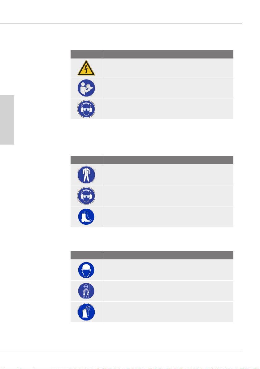
Sy m b o l s o n t h e m a c h i n e
The symbols on the machine have the following meaning:
Sy m b o l M e a n i n g
ENGLISH
Pe r s o n a l p r o t e c t i v e e q u i p m e n t
Wear the following protective equipment at all times when working
with the machine:
Sy m b o l M e a n i n g
Electric shock hazard!
Read the operating instructions before beginning
work!
Wear protective goggles and ear protection!
Close-tting work protection clothing with a low tearing resistance
Goggles for protecting eyes against ying parts and
liquids and ear protection in areas with noise emission
>80 dB(A)
Safety shoes to protect the feet from falling objects
Wear the following additional protective equipment during special
operations:
Sy m b o l M e a n i n g
Helmet to protect your head from falling objects
Wear a safety belt where there is a danger of falling
Working gloves as protection against injury
1 2
M AB 5 2 5
Page 13
C o m p o n e n t s / s c o p e o f s u p p l y
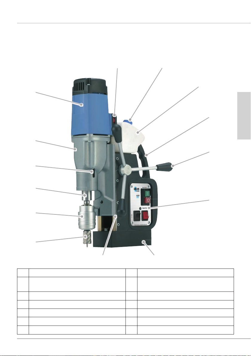
M a c h i n e o v e r v i e w
6
5
4
3
C o m p o n e n t s / s c o p e o f s u p p l y
87
9
1 0
ENGLISH
1 1
2
1
1 4
1 Core drill (not supplied as standard) 8 Filler neck for cutting oil
2 KEYLESS quick-change drill chuck
system tool mounting
3 Morse taper MK3 10 Handle
4 Opening for ejector pin 11 Hand lever
5 2-speed gearbox with selector 12 Control panel
6 Drive motor 13 Magnetic foot
7 Speed and torque controller 14 Machine slide and guide
9 Cutting oil tank
1 3
M AB 5 2 5
1 2
1 3
Page 14
C o m p o n e n t s / s c o p e o f s u p p l y
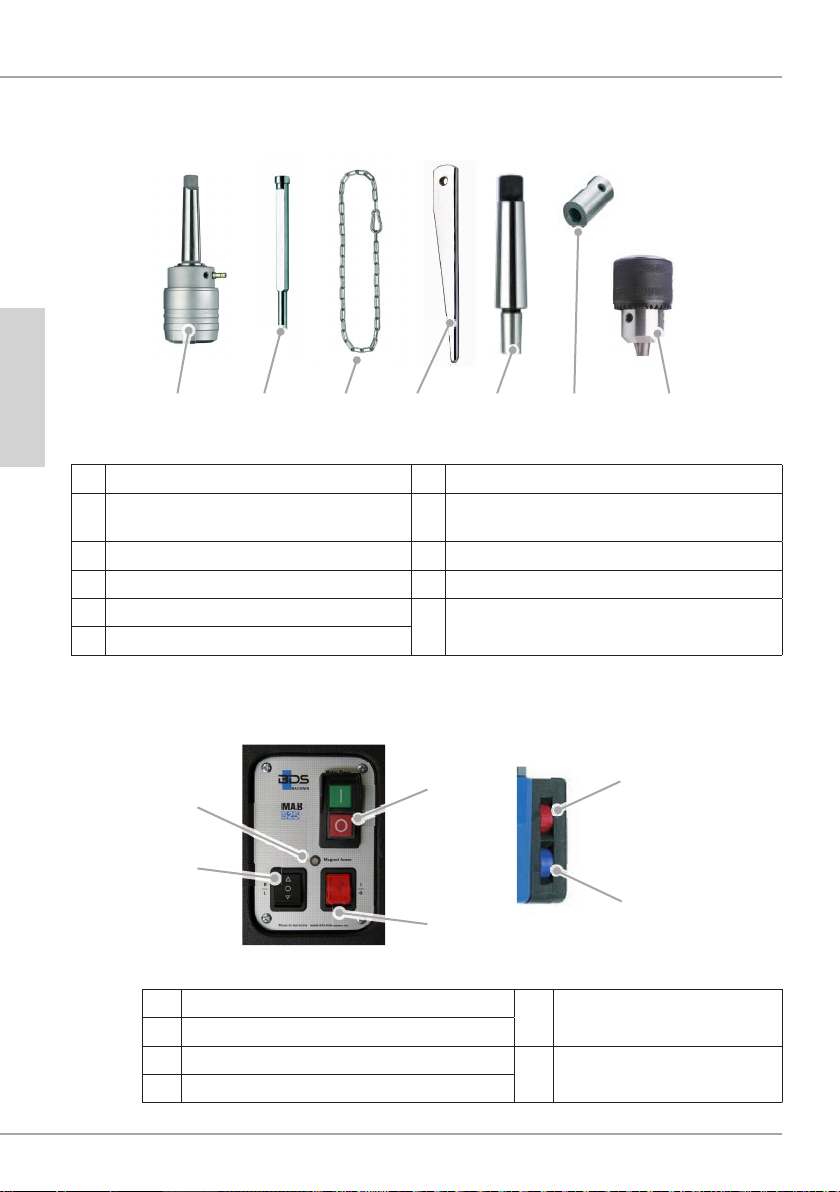
D e l i v e r y c o n t e n t s
ENGLISH
A B , C D E F G H
MAB 525 machine (not illustrated) F Tapered mandrel MK3/B16
A KEYLESS quick-change drill chuck
system
B Ejector pin ZAK 075 H Key-type drill chuck
C Ejector pin ZAK 100 Transport case (not illustrated)
D Safety chain Operating instructions/guarantee card
E Ejector pin MK3
G Adapter for thread taps M10/M12/M16
(not illustrated)
C o n t r o l p a n e l
2 1
2 4
2 3
2 2
3 2
3 1
21 Motor ON/OFF switch
22 Magnet ON/OFF switch
23 Direction of rotation switch
24 Magnet indicator
1 4
31 Speed setting
32 Torque setting
M AB 5 2 5
Page 15

Before using for the rst time
Before using for the rst time
T r a n s p o r t i n s p e c t i o n
The machine is supplied as standard with the components
indicated in chapter Components/scope of supply.
NOTE
► Inspect the delivery for completeness and obvious signs of
damage. Report an incomplete or damaged delivery to your
supplier/dealer immediately.
Pr e p a r a t i o n s
This chapter contains important instructions for the necessary
preparations before starting work.
Ad d i t i o n a l s a f e t y m e a s u r e s f o r c e r t a i n o p e r a t i o n s
Additional safety precautions must be taken for the following
operations with the machine:
No n - h o r i zo n t a l w o r k i n g p o s i t i o n
ENGLISH
M AB 5 2 5
W AR NING
R i s k o f i n j u r y f r o m t h e f a l l i n g m a c h i n e .
When working in inclined or vertical position and during
overhead work, the machine must be secured to prevent it from
falling using the safety chain (D) supplied.
► Check the safety chain for proper function before every
use. A damaged safety chain must not be used. Replace a
damaged safety chain immediately.
► Attach the safety chain in such a way that the machine
moves away from the operator in the event of slipping.
► Lay the safety chain as tightly as possible around the handle
of the machine.
► Check the secure tting of the safety chain and lock before
starting work.
► Use the protective equipment stipulated in chapter Personal
protective equipment.
1 5
Page 16

Pr e p a r a t i o n s
W o r k o n s c a f f o l d i n g
W AR NING
R i s k o f f a l l i n g f r o m s u d d e n o s c i l l a t i n g m o v e m e n t s o f t h e
m a c h i n e .
When working on scaffolding, the machine can make a sudden
oscillating movement on starting or in the event of a power
failure.
► Secure the machine with the safety chain (D) supplied.
► Wear a safety belt to protect yourself from falling.
C h e c k t h e c o n d i t i o n o f t h e s u b s t r a t e
ENGLISH
The magnet clamping force is dependent on the condition of the
substrate. The clamping force is signicantly reduced by paint,
zinc and scale coatings and rust.
The substrate must satisfy the following preconditions in order
that a sufcient magnet clamping force can be achieved:
■ The substrate must be magnetic.
■ The clamping surface and the magnetic foot (13) must be
clean and grease-free.
■ The clamping surface must be completely smooth and level.
NOTE
► Clean the substrate and the magnetic foot (13) of the
machine before use.
► Remove any unevenness and loose rust from the substrate.
► CS Unitec offers special holding devices in its range of
accessories.
The best clamping effect is obtained on low-carbon steel substrate
with a thickness of at least 3/4" (20 mm).
1 6
M AB 5 2 5
Page 17

St e e l o f l o w t h i c k n e s s
When drilling in steel of low thickness, an additional steel plate
(minimum dimensions 4" x 7-7/8" x 3/4" [100 x 200 x 20 mm])
must be placed under the workpiece. Secure the steel plate to
prevent it from falling.
NF m e t a l s o r w o r k p i e c e s w i t h a n u n e v e n s u r f a c e
A special holding device must be used when drilling in NF metals
or in workpieces with an uneven surface.
NOTE
► CS Unitec offers special clamping devices for tubes and
non-magnetic materials in its range of accessories.
In s e r t i n g t h e t o o l
The machine is equipped with an MK tool mounting. Depending
on the type of tool to be used, corresponding drill chucks, quickclamping systems or adapters must be employed.
T o o l T o o l m o u n t i n g t o b e u s e d
Tool with
taper MK
Insert the tool directly into the morse taper
(3).
Pr e p a r a t i o n s
ENGLISH
M AB 5 2 5
Tools with
19 mm Weldon shank
Tools with
straight shank
Thread taps
Use KEYLESS quick-change drill chuck
system (A).
Use key-type drill chuck (H) with tapered
mandrel MK3/B16 (F).
Use KEYLESS quick-change drill chuck
system (A) with the appropriate adapter
(G) for thread taps.
1 7
Page 18

Pr e p a r a t i o n s
Sa f e t y p r e c a u t i o n s
M K t o o l m o u n t i n g
ENGLISH
W AR NING
R i s k o f i n j u r y !
► Do not use damaged, soiled or worn tools.
► Carry out tool changes only when the machine is switched
off and at a standstill. Remove plug from the mains socket.
► After inserting, check that the tool is engaged securely.
► Only use tools, adapter and accessories that match the
machine.
In s e r t i n g t h e t o o l
Before mounting, clean the shank of the tool, adapter or drill
chuck and the morse taper (3) of the machine.
Push the tool from below into the morse taper (3) of the
machine.
W AR NING
R i s k o f i n j u r y f r o m i n c o r r e c t l y i n s e r t e d t o o l !
► Check the proper seating of the tool, adapter or drill chuck in
the MK tool mounting.
R e m o v i n g t h e t o o l
Turn the tool until the ejector pin (E) slips into the opening for
the ejector pin (4).
Prise out the tool with the ejector pin (4) or loosen the tool by
tapping against the ejector pin.
1 8
M AB 5 2 5
Page 19

K e y - t y p e d r i l l c h u c k
In s e r t i n g t h e t o o l
R e m o v i n g t h e t o o l
R i s k o f i n j u r y !
Al w a y s r e m o v e t h e c h u c k k e y f r o m t h e d r i l l c h u c k a f t e r
t i g h t e n i n g o r l o o s e n i n g .
Pr e p a r a t i o n s
Push the key-type drill chuck (H) onto the tapered
mandrel (F) and push the combination into the morse taper
(3) of the machine.
Open the drill chuck and insert the tool into the drill chuck.
Close the drill chuck by hand and then tighten the drill chuck
with the chuck key.
Unlock the drill chuck with the chuck key and remove the
tool.
W AR NING
► Tighten the drill chuck only with the chuck key provided.
ENGLISH
M AB 5 2 5
1 9
Page 20
Pr e p a r a t i o n s
K EY LESS q u i c k - c h a n g e d r i l l c h u c k s y s t e m
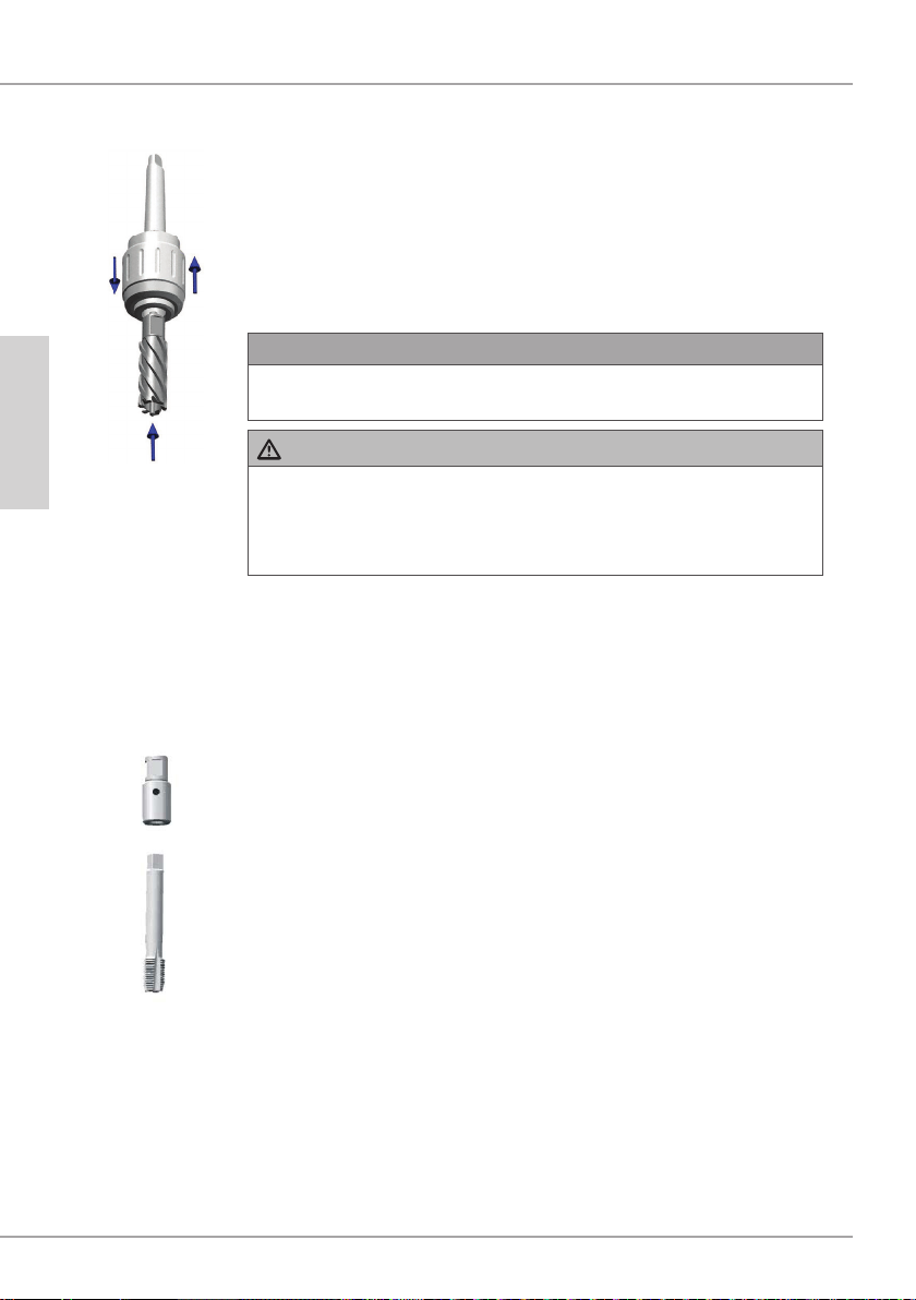
In s e r t i n g t h e t o o l
Push the KEYLESS quick-change drill chuck system (A) into
the morse taper (3) of the machine.
Connect the lubricant line.
Open the quick-change drill chuck system (A) by pushing up
the sleeve and insert the tool into the chuck.
NOTE
► Insert the appropriate ejector pin before inserting the core
drill.
ENGLISH
Ad a p t e r f o r t h r e a d t a p s
W AR NING
R i s k o f i n j u r y f r o m i n c o r r e c t l y i n s e r t e d t o o l o r t o o l
m o u n t i n g .
► Check by briey turning the tool whether the collet is
engaged.
R e m o v i n g t h e t o o l
Open the quick-change drill chuck system (A) by pushing up
the sleeve and pull the tool down out of the chuck.
In s e r t i n g t h e t o o l
Insert the thread tap into the appropriate adapter for thread
taps (G).
Insert the adapter with the thread tap (G) into the KEYLESS
quick-change drill chuck system (A).
R e m o v i n g t h e t o o l
Open the quick-change drill chuck system (A) by pushing up
the sleeve and pull the adapter for thread taps (G) down out
of the chuck system.
Pull the thread tap out of the adapter for thread taps (G).
2 0
M AB 5 2 5
Page 21

Op e r a t i o n
Ac t i v a t i n g / d e a c t i v a t i n g m a g n e t i c c l a m p
Ac t i v a t i n g m a g n e t i c c l a m p
CAUTION
► Switch on the magnetic clamp only when the machine is
standing on a magnetic substrate to avoid overheating of the
magnet.
Turn on switch (22). The indicator light in switch (22) comes
on.
Check the magnet clamping force at the magnet
indicator (24). When the magnet clamping force is sufcient,
the MAGNET POWER indicator light (24) is green. If the
MAGNET POWER indicator light (24) is red, there is not
sufcient magnet clamping force available.
CAUTION
► The maximum magnet clamping force is only available after
switching on the motor.
D e a c t i v a t i n g m a g n e t i c c l a m p
Secure the machine at the handle (10) to prevent the
machine from slipping off the surface.
Turn off switch (22). The indicator light in switch (22) goes
out.
Op e r a t i o n
ENGLISH
Sw i t c h i n g m a c h i n e ON/ OF F
Turn the machine ON at the ON/OFF switch (21) with the
green button (I) and OFF with the red button (O).
NOTE
► The machine can only be switched on when the magnetic
clamp has been switched on.
► Allow a severely overheated machine to run on at no-load
speed for approx. 2 minutes to let it cool down.
► The machine switches off automatically in the event of a
power failure or if the magnetic clamp is switched off.
M AB 5 2 5
2 1
Page 22

Op e r a t i o n
Se l e c t i n g t h e s p e e d r a n g e
The machine has a gearbox with two mechanical gear stages:
Gear stage 1: Load speed 280 rpm
Gear stage 2: Load speed 580 rpm
ENGLISH
Se t t i n g t h e s p e e d
In addition to the mechanical gearbox, the machine also has
full-wave control electronics with which the speed can be innitely
varied.
Gear stage 1: 70 - 280 rpm
Gear stage 2: 180 - 580 rpm
CAUTION
► Switch over the gear stages only with the machine at
standstill.
To select the desired gear stage, set selector lever (5) to
stage 1 or 2 with the machine switched off.
NOTE
► Select the speed range according to the material and drilling
diameter.
First set the appropriate gear stage, then adapt the speed
using the electronic speed control (7).
NOTE
► If possible, always select a setting with low gear stage and
high motor speed. The motor is thus set to high torque and
protected against overheating under heavy load.
2 2
M AB 5 2 5
Page 23

Se t t i n g t h e t o r q u e c u t - o u t
In order to protect the tool, the maximum torque of the machine
can be set using the controller (32).
When the maximum set torque is reached, the machine switches
off. After the cut-out, the machine must be switched off and then
on again at the ON/OFF switch (21).
CAUTION
► Do not use this function to switch off the machine when
cutting threads in pocket holes.
D r i l l i n g w i t h t h e m a c h i n e
D r i l l i n g w i t h t w i s t d r i l l s
Proceed as follows when drilling with twist drills:
Push twist drills with MK taper from below into the morse
taper (3) of the machine.
Push twist drills with straight shank into the drill chuck after
tting the drill chuck (H).
Position the machine at the working location, align it and
switch on the magnetic clamps.
Select the appropriate speed and switch on the machine.
Op e r a t i o n
ENGLISH
M AB 5 2 5
NOTE
Observe the following instructions when drilling with twist drills:
► Under high pressure, the drill can glow out and the machine
can be overloaded.
► When working overhead, use the high-performance grease
spray ZHS 400. Spray the drill with grease spray before
drilling. Repeat the procedure when drilling deep holes.
► Pay attention to a regular chip discharge. With larger drilling
depths, break the chip.
2 3
Page 24

Op e r a t i o n
D r i l l i n g w i t h c o r e d r i l l s
ENGLISH
Proceed as follows when drilling with core drills:
Install the quick-change drill chuck system (A) and connect
up the cooling lubricant system.
Install the appropriate ejector pin in the core drill and insert
the core drill into the quick-change drill chuck system (A).
Position the machine at the working location, align it and
switch on the magnetic clamps.
Select the appropriate speed and switch on the machine.
NOTE
Observe the following instructions when drilling with core drills:
► Drilling with core drills requires no great effort. The drilling
process is not accelerated by higher pressure. The drill
wears faster and the machine can be overloaded.
► Use the cooling lubricant system installed on the machine
with high-performance cutting oil from CS Unitec.
► The cooling lubricant system cannot be used when working
overhead. In this case use the high-performance grease
spray ZHS 400. Spray the drill on the inside and outside
before drilling. Repeat this procedure when drilling deeper
holes.
► Pay attention to a regular chip discharge. With larger drilling
depths, break the chip.
2 4
M AB 5 2 5
Page 25

T h r e a d c u t t i n g
Op e r a t i o n
The machine is equipped with a reversible direction of rotation
and can also be used for cutting threads.
Proceed as follows for cutting threads:
Drill the hole for the thread.
Switch off the machine and select the lowest gear stage and
speed.
Set the direction of rotation to clockwise (right = R) at switch
(23).
Chuck the thread tap in the machine using the appropriate
drill tap adapter.
Switch on the machine and set the thread tap onto the drilled
hole.
Guide the machine slide down at hand lever (11) without
exerting pressure until the desired thread length has been
cut.
Switch off the machine and set the direction of rotation to
anti-clockwise (left = L) at switch (23).
Switch on the machine again and allow the thread tap to
come completely out of the workpiece. Then guide the
machine slide upwards at hand lever (11) to avoid damaging
the start of the thread.
ENGLISH
R e a m i n g / c o u n t e r - s i n k i n g
Thanks to its wide range of operating speeds, the machine can
also be used for reaming or counter-sinking.
CAUTION
► Observe the limits of the tools to be used for reaming and
counter-sinking given in the technical data.
M AB 5 2 5
2 5
Page 26

El i m i n a t i n g b l o c k a g e s
El i m i n a t i n g b l o c k a g e s
W AR NING
D a n g e r o f c u t t i n g b y b r o k e n t o o l p a r t s o r s h a v i n g s .
► Put protective gloves on before starting work.
B l o c k a g e s c a u s e d b y a b r o k e n t o o l :
Switch off the machine. Remove plug from the mains socket.
Use the handle to move the machine slide to the upper
position.
Replace defective tool. Remove shavings.
ENGLISH
Ot h e r b l o c k a g e s :
Switch the machine of at the motor switch. Leave magnetic
clamp switched on.
Use the handle to move the machine slide to the upper
position.
Remove shavings and check tool.
2 6
M AB 5 2 5
Page 27

C l e a n i n g
C l e a n i n g
W AR NING
► Switch off the machine and pull the mains plug out of the
plug socket before starting maintenance and cleaning.
► When using compressed air for cleaning, wear protective
goggles and protective gloves and protect other persons in
the working area.
CAUTION
► Never immerse the machine in water or other liquids.
Af t e r e v e r y u s e
ENGLISH
Remove the installed tool.
Remove chips and coolant residues.
Clean the tool and the tool mounting on the machine.
Clean the guide of the machine slide.
Return the machine and accessories to the transport case.
M AB 5 2 5
2 7
Page 28

M a i n t e n a n c e
M a i n t e n a n c e
W AR NING
Danger caused by unqualied repairs!
Unqualied repairs can pose considerable dangers for the user
and cause damage to the machine.
► Repairs to electrical appliances may only be carried out by
the works after-sales service or by specialists trained by the
manufacturer.
Ad j u s t i n g t h e g u i d e o f t h e m a c h i n e s l i d e
If the guide of the machine slide (14) shows signs of backlash, it
ENGLISH
R e p l a c i n g t h e c a r b o n b r u s h e s
must be adjusted. Proceed as follows:
Loosen the clamping bolts.
Tighten the adjusting screws uniformly.
Tighten the clamping bolts again.
Replacement of the carbon brushes may only be carried out by
CS Unitec or by an authorised repair workshop. Unauthorised
repairs will void the warranty.
Af t e r - Sa l e s Se r v i c e / Se r v i c e
Should you have any questions about after-sales service or
service, please contact CS Unitec. We will be happy to give you
the address of your nearest service partner.
2 8
M AB 5 2 5
Page 29

T r o u b l e s h o o t i n g
F a u l t s - c a u s e s a n d r e m e d i e s
F a u l t Po s s i b l e c a u s e R e m e d y
Plug not inserted into socket. Insert plug.
T r o u b l e s h o o t i n g
The motor does not start
after pressing the ON/
OFF switch or stops during
operation.
The automatic circuit
breaker in the electrical
distribution board trips
The magnetic clamp does
not function.
The lubrication system
does not function.
Automatic circuit breaker
tripped.
The magnetic clamp is not
switched on.
The internal safety switch
has switched off the machine
due to overheating.
Direction of rotation not
selected.
The torque cut-out has
tripped.
Too many appliances connected to the same power
circuit.
Machine is defective. Contact After-sales Service.
Magnet not switched on. Switch on magnet.
The surface is not magnetic. Use a suitable base.
No lubricant available. Top up the lubricant.
Lubricant tap closed. Open the lubricant tap.
Connecting nipple clogged. Clean tank and nipple.
Switch on the automatic circuit
breaker again.
Switch on the magnetic clamp.
Allow the machine to cool
down.
Preselect direction of rotation.
Switch the machine off and on
again.
Reduce the number of appliances on the power circuit.
ENGLISH
NOTE
► If you cannot resolve the problem with the steps described above, please contact
After-Sales Service.
M AB 5 2 5
2 9
Page 30

St o r a g e / d i s p o s a l
St o r a g e / d i s p o s a l
St o r a g e
D i s p o s a l
ENGLISH
If you do not intend to use the machine for a longer period of time,
clean it as described in chapter Cleaning. Store the machine and
all the accessories in the transport case in a dry, clean and frostfree location.
D i s p o s a l o f t h e p a c k a g i n g
The packaging protects the machine from transport damage.
The packaging materials have been selected according to
environmental and waste disposal aspects and can therefore be
recycled.
The return of the packaging to the material cycle helps conserve
raw materials and reduces the production of waste.
When no longer required, dispose of the packaging materials in
accordance with the local regulations in force.
D i s p o s a l o f t h e o l d a p p l i a n c e
Within the European Community, this product must not be
disposed of in the domestic refuse.
Dispose of the product in accordance with the EC Directive
2002/96/EC-WEEE (Waste Electrical and Electronic Equipment).
Should you have any questions, please contact your local
authority responsible for waste disposal.
D i s p o s a l o f t h e l u b r i c a n t
W AR NING
► Observe the disposal instructions from the lubricant
manufacturer.
3 0
M AB 5 2 5
Page 31

An n e x
T e c h n i c a l d a t a
Model M AB 5 2 5
Dimensions (L x W x H)
Magnetic foot (L x W) 7-1/8" x 3-1/2" (180 x 90 mm)
Net weight approx. 35 lbs. (16 kg)
Operating voltage (see type plate)
Power consumption 14.5 Amp / 110 V (1600 W)
Noise level 89 db(A)
Vibration 0.85 m/s²
Stroke 6-1/3" (160 mm)
Hole Capacity 2-1/2" dia.
Core drill, short dia. 1/2" - 2" (12-50 mm)
Core drill, long dia. 1/2" - 2" (12-50 mm)
11-3/4" x 6-3/4" x 19" (to 25-1/8")
(300 x 171 x 637 mm)
230 V / 50-60 Hz
110-125 V / 50-60 Hz
An n e x
ENGLISH
Twist drill max. dia. 1"
Thread max. M20
Reaming max. dia. 7/8"
Counter-sinking max. dia. 2" (50 mm)
Speed stage 1 n
Speed stage 2 n
Overheating protection Yes
Variable torque Yes
Full-wave control electronics Yes
Clockwise/anti-clockwise rotation Yes
Morse taper MT3 (MK3)
Core drill mounting KEYLESS MT3 / 3/4" (MK3/19mm) Weldon
Length of the connecting lead: 9 ft. (2.8 m)
Protection class I
= 70 - 280 rpm
0
= 180 - 580 rpm
0
M AB 5 2 5
3 1
Page 32

An n e x
EC D e c l a r a t i o n o f C o n f o r m i t y
Name/address of manufacturer: B D S M a s c h i n e n Gm b H
Martinstraße 108
D-41063 Mönchengladbach
We hereby declare that the product
Model: M a g n e t i c c o r e d r i l l i n g m a c h i n e
ENGLISH
Type: M AB 5 2 5
conforms to the following relevant regulations:
The following harmonised standards were applied in whole or in part:
Responsible person for documentation according to EC Directive 2006/42/EC - An-
nex II Pt.A.2. was:
■ EC D i r e c t i v e 2 0 0 6 / 4 2 / EC o n m a c h i n e r y
■ EU D i r e c t i v e 2 0 0 4 / 1 0 8 / EU o n El e c t r o m a g n e t i c C o m p a t i b i l i t y .
● DIN EN ISO 12100:2010
● DIN EN 61000-6-4:2007 + A1:2011
● DIN EN 55014-1:2006 + A1:2009 + A2:2011
● DIN EN 55014-2:1997 + Corr. 1997 + A1:2001 + A2:2008
● DIN EN 60745-1:2009
● DIN EN 60745-2-1:2010
_____________________________________________________________________
(Surname, forename, position in company of the manufacturer)
Mönchengladbach, 1st June 2012
3 2
Wolfgang Schröder, Technical Director
________________________________________
(Legally binding signature of the issuer)
M AB 5 2 5
Page 33

Í n d i c e
Pr ó l o g o . . . . . . . . . . . . . . . . . . . . . . . . . 3 4
In d i c a c i o n e s d e u s o . . . . . . . . . . . . . . . 3 4
Derechos de autor .................34
Composición de las advertencias ......35
Uso conforme al previsto ............36
Limitación de responsabilidades ......36
Se g u r i d a d . . . . . . . . . . . . . . . . . . . . . . . 3 7
Indicaciones básicas de seguridad ....37
Peligros relacionados con la electricidad
Peligro de lesiones .................39
Prevención de daños ...............40
Dispositivos de seguridad ...........41
Equipamiento de protección personal
C o m p o n e n t e s / v o l u m e n d e s u m i n i s t r o
Sinóptico de máquinas ..............43
Volumen de suministro ..............44
Panel de operación ................44
An t e s d e u t i l i za r p o r p r i m e r a v e z . . . . 4 5
Inspección de transporte ............45
Pr e p a r a t i v o s . . . . . . . . . . . . . . . . . . . . . 4 5
Medidas de seguridad adicionales
para determinados trabajos. ..........45
Comprobar la consistencia del
fundamento ......................46
Insertar herramienta ................47
. .38
...42
. . 4 3
U t i l i za c i ó n . . . . . . . . . . . . . . . . . . . . . . 5 1
Conectar/desconectar imán de adherencia
Conectar/desconectar la máquina .....51
Seleccionar el rango de revoluciones . .52
Ajuste de revoluciones ..............52
Ajustar la desconexión del par de giro
Taladrar con la máquina .............53
Fileteado de rosca .................55
Escariado/Avellanado ...............55
El i m i n a c i ó n d e b l o q u e o s . . . . . . . . . . . 5 6
Li m p i e za . . . . . . . . . . . . . . . . . . . . . . . . 5 7
Después de cada uso ...............57
M a n t e n i m i e n t o . . . . . . . . . . . . . . . . . . . 5 8
Reajustar la guía del carro de máquina
Cambiar las escobillas ..............58
Asistencia técnica / Servicio técnico ...58
So l u c i ó n d e a n o m a l í a s . . . . . . . . . . . . 5 9
Causa y solución de anomalías .......59
Al m a c e n a m i e n t o y e l i m i n a c i ó n . . . . . . 6 0
Almacenamiento ...................60
Eliminación .......................60
An e x o . . . . . . . . . . . . . . . . . . . . . . . . . . 6 1
Datos técnicos ....................61
Declaración de conformidad de la CE
.51
...53
...58
...62
ESPAÑOL
Distributed exclusively by:
22 Harbor Avenue, Norwalk, CT 06850 USA
Toll-Free: 800-700-5919 • Phone: 203-853-9522
Fax: 203-853-9921 • Email: info@csunitec.com
www.csunitec.com
BA_MAB525_0310_A3 © 2012 BDS Maschinen GmbH
3 3M AB 5 2 5
Page 34

Pr ó l o g o
Pr ó l o g o
Con la compra de la máquina ha optado por un producto de
calidad que ha sido dimensionado respecto a su tecnología
y robustez para las más altas exigencias en su utilización
profesional diaria.
Lea la información de este manual con el n de familiarizarse
rápidamente con la máquina y de poder sacar el máximo
provecho todas sus funciones.
Si trata y cuida correctamente su aparato le hará un buen servicio
durante muchos años.
In d i c a c i o n e s d e u s o
El presente manual de instrucciones forma parte de la taladradora
de núcleo magnética MAB 525 (en adelante máquina) contiene
información importante acerca de la puesta en funcionamiento,
la seguridad, el uso conforme al previsto y el cuidado de la
máquina.
El manual de instrucciones debe estar guardado siempre cerca
de la máquina. Ha de ser leído y aplicado por toda persona que
esté encargada del manejok, solución de averías y/o limpieza de
la máquina.
Guarde debidamente este manual de instrucciones y entréguelo
junto al aparato a su propietario futuro.
D e r e c h o s d e a u t o r
ESPAÑOL
3 4
Este documento está protegido por las leyes de derechos de
autor.
Queda prohibida la reproducción y reimpresión total o parcial
del manual, así como la copia de sus ilustraciones, con o sin
modicaciones, sin la autorización por escrito del fabricante.
M AB 5 2 5
Page 35

C o m p o s i c i ó n d e l a s a d v e r t e n c i a s
En el presente manual de instrucciones se utilizan las siguientes
advertencias:
PELIGR O
La s i n d i c a c i o n e s d e e s t a c a t e g o r í a s e ñ a l a n u n a p o s i b l e
s i t u a c i ó n d e p e l i g r o .
Si no se toman las medidas necesarias para evitar esta
situación, podría provocar lesiones personales graves e incluso
la muerte.
► Las instrucciones contenidas en esta indicación tienen la
nalidad de impedir la muerte o lesiones graves para las
personas.
AD V ER T ENC IA
La s i n d i c a c i o n e s d e e s t a c a t e g o r í a s e ñ a l a n u n a s i t u a c i ó n
d e p e l i g r o p o t e n c i a l .
Si no se toman las medidas necesarias para evitar esta
situación, podría provocar lesiones personales.
► Las instrucciones contenidas en esta indicación tienen la
nalidad de impedir lesiones para las personas.
In d i c a c i o n e s d e u s o
M AB 5 2 5
ATENCIÓN
La s i n d i c a c i o n e s d e e s t a c a t e g o r í a s e ñ a l a n d a ñ o s
m a t e r i a l e s p o t e n c i a l e s .
Si no se toman las medidas necesarias para evitar esta
situación, podría provocar daños materiales.
► Las instrucciones contenidas en esta indicación tienen la
nalidad de impedir daños materiales.
NOTA
► Una nota contiene informaciones adicionales para facilitar el
uso del aparato.
ESPAÑOL
3 5
Page 36

In d i c a c i o n e s d e u s o
U s o c o n f o r m e a l p r e v i s t o
La máquina ha sido diseñada para trabajos de taladrado en
metales magnéticos y no magnéticos asi como para el aterrajado
de roscas, avellanado y escariado conforme a los limites
indicados en los datos técnicos.
Cualquier uso diferente o excedente se considerará no conforme
al previsto.
AD V ER T ENC IA
¡ Pe l i g r o d e r i v a d o d e u n u s o n o c o n f o r m e a l p r e v i s t o !
Si la máquina no es utilizada de la forma prevista y/o se utiliza
para nes distintos pueden producirse situaciones de peligro.
► Utilice el aparato únicamente conforme a su uso previsto.
► Cumpla con los procedimientos que se describen en este
manual de instrucciones.
Las reclamaciones por daños derivados del uso no conforme al
previsto quedarán invalidadas de forma inmediata.
El riesgo es responsabilidad única del usuario.
NOTA
► Si usa la máquina para nes profesionales, tenga en
cuenta las normativas de prevención de accidentes y las
disposiciones de seguridad de la empresa.
Li m i t a c i ó n d e r e s p o n s a b i l i d a d e s
Toda la información técnica, datos e indicaciones sobre la
instalación, el funcionamiento y el cuidado incluidas en el
presente manual de instrucciones se corresponden al estado más
actual en el momento de su impresión.
ESPAÑOL
3 6
El fabricante no se hace responsable de los daños derivados
del incumplimiento de las instrucciones, del uso no conforme al
previsto, de las reparaciones indebidas, de las modicaciones
realizadas sin autorización o del uso de accesorios y piezas de
repuesto, herramientas y lubricantes no permitidos.
M AB 5 2 5
Page 37

Se g u r i d a d
AT ENC IÓ N
¡ D u r a n t e l a u t i l i za c i ó n d e h e r r a m i e n t a s e l é c t r i c a s d e b e n
o b s e r v a r s e l a s s i g u i e n t e s m e d i d a s d e s e g u r i d a d b á s i c a s
con el n de evitar descargas eléctricas y peligros de
l e s i o n e s e i n c e n d i o !
In d i c a c i o n e s b á s i c a s d e s e g u r i d a d
■ No utilice la máquina en ambientes con riesgo de incendio o
explosión.
■ Aquellas personas cuyas capacidades físicas, psíquicas
o motrices no les permitan utilizar la máquina con plena
seguridad únicamente podrán usarla bajo supervisión o con
las instrucciones de una persona responsable.
■ Queda prohibido el uso de la máquina a las personas que
lleven marcapasos o cualquier otros implantes medicinales.
■ A los niños no se le está permitido utilizar la máquina
■ Antes de utilizar la máquina, revise que la máquina y el cable
de conexión no presenten daños externos. No ponga en
funcionamiento una máquina dañada.
■ Antes de empezar a trabajar, compruebe que la cadena de
seguridad se encuentre en perfecto estado y que el interruptor
de la máquina funcione correctamente.
■ Encargue las reparaciones del cable de conexión únicamente
a un técnico electricista.
■ Encargue las reparaciones del aparato sólo a un distribuidor
autorizado o al servicio técnico de fábrica. Una reparación
indebida puede provocar situaciones graves de peligro para el
usuario.
■ Las reparaciones del aparato dentro del periodo de garantía
deberán ser realizadas únicamente por un servicio técnico
autorizado por el fabricante, ya que de lo contrario perderá el
derecho a la garantía.
■ Los componentes defectuosos se deberán sustituir
únicamente por piezas de repuesto originales. Ésta es la
única forma de garantizar que se cumplan los requisitos de
seguridad.
Se g u r i d a d
ESPAÑOL
M AB 5 2 5
3 7
Page 38

Se g u r i d a d
■ No deje la máquina desatendida cuando esté en
funcionamiento.
■ Guarde la máquina en un lugar seco y con una temperatura
agradable fuera del alcance de los niños.
■ No deje la máquina al aire libre ni la exponga a la humedad.
■ Asegúrese de que el lugar de trabajo esté sucientemente
iluminado (>300 Lux).
■ No utilice máquinas de baja potencia para realizar trabajos
pesados.
■ Mantenga el lugar de trabajo limpio.
■ Mantenga la máquina limpia, seca y libre de residuos de
aceite y grasa.
■ Respete las instrucciones de lubricación y refrigeración de la
herramienta.
Pe l i g r o s r e l a c i o n a d o s c o n l a e l e c t r i c i d a d
PELIGR O
¡ Pe l i g r o d e m u e r t e d e b i d o a l a c o r r i e n t e e l é c t r i c a !
¡ El c o n t a c t o c o n c a b l e s o c o m p o n e n t e s c a r g a d o s c o n
t e n s i ó n i m p l i c a p e l i g r o d e m u e r t e !
A n de impedir situaciones de peligro relacionadas con la
electricidad, respete las siguientes indicaciones de seguridad:
► No abra la carcasa de la máquina. Si se tocan contactos
sometidos a tensión existe un riesgo de descarga eléctrica.
► Nunca sumerja en agua o en otro líquido la máquina o la
clavija de red.
► Utilice exclusivamente prolongadores o tambores
portacables con una sección de cable de 1,5 mm².
ESPAÑOL
► Utilice únicamente cables alargadores homologados para el
lugar de uso de la máquina.
► Revise el estado del cable alargador de forma regular y
sustitúyalo si está deteriorado.
► Evite el contacto entre el cuerpo y las piezas conectadas
a tierra (p.ej. tubos, radiadores o soportes de acero)
para reducir el peligro de descarga eléctrica en caso de
producirse una avería.
3 8
M AB 5 2 5
Page 39

Pe l i g r o d e l e s i o n e s
¡ Pe l i g r o d e l e s i o n e s e n c a s o d e u n u s o i n a d e c u a d o d e l a
m á q u i n a !
A n de no resultar herido usted u otras personas, respete las
siguientes indicaciones de seguridad:
Se g u r i d a d
AD V ER T ENC IA
► Utilice la máquina sólo con el equipamiento de protección
(véase capítulo equipamiento de protección personal)
indicado en el presente manual.
► Cuando la máquina esté en marcha, n o utilice guantes de
protección. Los guantes podrían quedarse encanchados
en la taladradora y ser arrancados de las manos. Si esto
llegara a suceder, podría perder uno o varios dedos.
► Quítese las joyas sueltas antes de empezar a trabajar. Si
tiene el pelo largo, recójaselo con una redecilla.
► Apague la máquina antes de proceder a cualquier cambio
de herramienta o de cualquier trabajo de mantenimiento o
limpieza. Espere hasta que deje de girar la máquina.
► Antes de cambiar una herramienta o de realizar algún
trabajo de mantenimiento o limpieza, desenchufe la clavija
de red de la toma de corriente para impedir que la máquina
se pueda poner en marcha de forma accidental.
► No acerque las manos a las piezas móviles de la
herramienta mientras esté en marcha. Extraiga las virutas
sólo con la máquina parada. Para retirar las virutas, utilice
guantes de protección.
► Durante los trabajos sobre un andamio el usuario deberá
estar asegurado mediante un arnés de sujeción contra
caídas ya que la máquina puede producir en caso de un
fallo de corriente un impacto pendular.
► Compruebe antes de cada uso que los imanes eléctricos
tengan una estabilidad segura sobre la base (véase capítulo
Preparativos).
► Cuando trabaje en una postura inclinada o vertical o por
encima de la cabeza, asegure la máquina con la cadena de
seguridad suministrada. La máquina podría desprenderse al
soltar el imán o por ausencia de tensión.
► Compruebe antes de cada uso el asiento seguro de la
herramienta (véase capítulo Insertar herramienta).
► No deje el cable de conexión colgando en esquinas (efecto
tropiezo).
ESPAÑOL
M AB 5 2 5
3 9
Page 40

Se g u r i d a d
Pr e v e n c i ó n d e d a ñ o s
ATENCIÓN
¡ Po s i b i l i d a d d e d a ñ o s m a t e r i a l e s s i e l a p a r a t o s e m a n i p u l a
i n c o r r e c t a m e n t e !
A n de impedir que se produzcan daños materiales, respete
las siguientes indicaciones:
► Antes de conectar la máquina, compare los datos
de conexión (tensión y frecuencia) de la placa de
características con los de la red eléctrica. Para que la
máquina no resulte dañada, deben coincidir estos datos.
► Coja la máquina siempre por el asidero y no por el cable de
conexión.
► Para desenchufar el cable de conexión de la toma de
corriente, tire siempre cogiéndolo por la clavija de red y
nunca por el cable de alimentación.
► No aplaste el cable de conexión.
► No exponga el cable de conexión al calor ni a productos
químicos.
► No pase el cable de conexión por encima de bordes alados
ni supercies calientes.
► Coloque el cable de conexión de modo que no pueda ser
capturado y enrollado por piezas en rotación de la máquina.
ESPAÑOL
4 0
M AB 5 2 5
Page 41

D i s p o s i t i v o s d e s e g u r i d a d
Pr o t e c c i ó n c o n t r a r e a r r a n q u e
NOTA
► La máquina se para automáticamente al desconectar el
imán de adherencia o en caso de un fallo de corriente.
Para evitar un arranque inesperado de la máquina al volver
a conectar los imanes de sujeción o bien al restablecerse la
alimentación de corriente (protección contra rearranque), la
máquina se ha de volver a conectar mediante el interruptor de
conexión/desconexión.
In d i c a d o r m a g n é t i c o
El indicador magnético sirve para el control óptico de la fuerza de
sujeción magnética.
■ El indicador magnético se ilumina V ER D E:
La fuerza de sujeción magnética corresponde a los requisitos
mínimos. El mecanizado puede realizarse.
■ El indicador magnético se ilumina R OJ O:
La fuerza de sujeción magnética es insuciente. No se puede
realizar ningún mecanizado con la máquina. Ello puede
ser debido a grosor de material insuciente, supercies
irregulares o bien por capas de laca, de escamas de óxido o
de cinc.
Se g u r i d a d
Pr o t e c c i ó n c o n t r a e l s o b r e c a l e n t a m i e n t o
La máquina va equipada además con una protección de
sobretemperatura. Si la máquina se calienta en exceso, se
desconecta automáticamente.
Antes de continuar trabajando con la máquina realice los pasos
siguientes::
Elimine los posibles bloqueos.
Deje funcionando la máquina en vacío durante apróx. 2
minutos.
A continuación la máquina esta de nuevo lista para usar.
M AB 5 2 5
ESPAÑOL
4 1
Page 42

Se g u r i d a d
Sí m b o l o s d e l a m á q u i n a
Los símbolos que hay colocados en la máquina tienen el
siguiente signicado:
Sí m b o l o Signicado
¡Peligro de descarga eléctrica!
Lea las instrucciones de servicio antes de empezar a
trabajar.
Utilice protección auditiva y gafas de protección.
Eq u i p a m i e n t o d e p r o t e c c i ó n p e r s o n a l
Durante los trabajos con la máquina se ha de llevar puesto el
equipamiento de protección personal siguiente:
Sí m b o l o Signicado
Ropa protectora de trabajo ceñida con baja resistencia a la rotura
Gafas de protección para protegerse los ojos contra
las piezas y los líquidos que pudieran salir despedidos, y protección auditiva en los lugares con emi-
siones acústicas > 80 dB(A)
ESPAÑOL
4 2
Calzado de seguridad como protección contra objetos
desprendidos
Durante trabajos especiales con la máquina se ha de llevar
puesto el equipamiento de protección personal adicional
siguiente:
Sí m b o l o Signicado
Casco de protección como protección contra objetos
desprendidos
Llevar puesto un arné de sujeción en caso de riesgo
de caída
Guantes protectores como protección contra lesiones
M AB 5 2 5
Page 43

C o m p o n e n t e s / v o l u m e n d e s u m i n i s t r o
C o m p o n e n t e s / v o l u m e n d e s u m i n i s t r o
Si n ó p t i c o d e m á q u i n a s
6
5
4
3
87
9
1 0
1 1
2
1
1 4
1 Broca hueca (no contenido en el volu-
men de suministro)
Portaherramientas Sistema de taladrado
2
de cambio rápido KEYLESS
Cono de husillo MK3
3
4 Apertura para extractor 11 Palanca de mano
5 Engranaje de dos velocidades con
conmutación
6 Motor de accionamiento 14 Carro de máquinas y guía
7 Regulación de revoluciones y de par de
8 Boquilla de llenado para aceite de corte
9 Depósito de aceite de corte
10 Asidero
12 Panel de operación
13 Pie magnético
1 3
giro
M AB 5 2 5
1 2
ESPAÑOL
4 3
Page 44

C o m p o n e n t e s / v o l u m e n d e s u m i n i s t r o
V o l u m e n d e s u m i n i s t r o
A B , C D E F G H
Máquina MAB 525 (sin gura) F Cono morse MK3/B16
A Sistema de taladrado de cambio
rápido KEYLESS
B Pasador de expulsión ZAK 075 H Portabrocas de corona dentada
C Pasador de expulsión ZAK 100 Maleta de transporte
D Cadena de seguridad Manual de instrucciones / tarjeta de gaE Extractor MK3
G Adaptador para machos de roscar
M10/M12/M16
(sin ilustración)
rantía (sin ilustración)
Pa n e l d e o p e r a c i ó n
ESPAÑOL
21 Interruptor de encendido y apagado del motor
22 Interruptor de encendido y apagado del imán
23 Conmutación sentido de giro
24 Indicador magnético
4 4
2 1
2 4
2 3
2 2
31
32 Ajuste del par de giro
3 2
3 1
Ajuste de las
revoluciones
M AB 5 2 5
Page 45

An t e s d e u t i l i za r p o r p r i m e r a v e z
An t e s d e u t i l i za r p o r p r i m e r a v e z
In s p e c c i ó n d e t r a n s p o r t e
La máquina viene de serie equipada con los componentes
indicados en el capítulo componentes/volumen des suministro.
NOTA
► Compruebe que el volumen de suministro esté completo
y que no presente daños visibles. Si el suministro está
incompleto o en mal estado, informe inmediatamente al
proveedor/comercio.
Pr e p a r a t i v o s
El presente capítulo contiene indicaciones importantes acerca
de las actividades de preparación necesarias antes de iniciar el
trabajo.
M e d i d a s d e s e g u r i d a d a d i c i o n a l e s p a r a d e t e r m i n a d o s t r a b a j o s .
En los trabajos relacionados a continuación se han de tomar las
medidas de seguridad adicionales siguientes:
Po s i c i ó n d e t r a b a j o n o h o r i zo n t a l
AD V ER T ENC IA
Pe l i g r o d e l e s i o n e s p o r c a í d a d e l a m á q u i n a
Cuando se realicen trabajos en posición vertical o inclinada o
por encima de la cabeza, la máquina ha de asegurarse con la
cadena de seguridad (D) suministrada contra caída.
► Compruebe el buen funcionamiento de la cadena de
seguridad antes de utilizarla. Queda prohibido usar una
cadena de seguridad dañada. Cambie la cadena de
seguridad dañada de inmediato.
► Coloque la cadena de seguridad de modo que se aleje la
máquina del usuario en caso de desprendimiento.
► Coloque la cadena de seguridad dentro de lo posible sin
holgura alrededor del asidero de la máquina.
► Compruebe antes de comenzar los trabajos el rme asiento
de la cadena de seguridad y el cierre.
► Utilice el equipamiento de protección indicado en el capítulo
Equipamiento de protección personal.
M AB 5 2 5
ESPAÑOL
4 5
Page 46

Pr e p a r a t i v o s
T r a b a j o s s o b r e u n a n d a m i o
AD V ER T ENC IA
R i e s g o d e c a í d a d e b i d o a u n m o v i m i e n t o p e n d u l a r
i n e s p e r a d o d e l a m á q u i n a .
Durante los trabajos sobre un andamio, la máquina puede
producir durante el arranque o en caso de fallo de corriente un
movimiento pendular inesperado.
► Asegure la máquina con la cadena de seguridad
adjunta (D).
► Asegurese contra caída llevando puesto el arné de sujeción.
C o m p r o b a r l a c o n s i s t e n c i a d e l f u n d a m e n t o
La fuerza de sujeción magnética depende de la naturaleza del
fundamento. La fuerza de sujeción es reducida notablemente por
capas de pintura, de cinc y de cascarilla así como por óxido.
El fundamento para que se pueda establecer una adherencia
magnética suciente, deberá cumplir las condiciones siguientes:
■ El fundamento deberá ser magnético.
■ La supercie de adherencia y el pie magnético (13) deberán
estar limpios y libre de grasa.
■ La supercie de adherencia no deberá ser irregular.
ESPAÑOL
4 6
NOTA
► Antes de usar limpie la base y el pie magnético (13) de la
máquina.
► Elimine las irregularidades y el óxido suelto de la base.
► CS Unitec le ofrece en su gama de accesorios útiles de
sujeción especiales.
El mejor efecto de adherencia se logra con acero de bajo
contenido en carbono y un espesor mínimo de 20 mm.
M AB 5 2 5
Page 47

Ac e r o d e e s p e s o r r e d u c i d o
Para taladrar en acero de espesor reducido, se ha de colocar una
placa de acero adicional (dimensión mínima 100 x 200 x 20 mm)
debajo de la pieza. Asegure la placa de acero contra caída.
Metales no férricos o bien piezas con supercies no planas
Para taladrar en metales no férricos o bien en piezas con
supericies no planas, se ha de utilizar un úitl de sujeción
especial.
NOTA
► CS Unitec le ofrece en su gama de accesorios dispositivos
de sujeción para tubos y materiales no magnéticos.
In s e r t a r h e r r a m i e n t a
La máquina va dotada de un portaherramientas MK (cono morse).
Según el tipo de herramienta a utilizar se han de utilizar mandriles
portabrocas, sistemas de sujeción rápida o bien adaptadores
correspondientes.
He r r a m i e n t a Po r t a h e r r a m i e n t a s a u t i l i za r
Herramientas con
cono MK
Herramientas para su inserción directa en
el cono de husillo (3).
Pr e p a r a t i v o s
M AB 5 2 5
Herramientas con
mango Weldon 19 mm
Herramientas con
mango recto
Machos de roscar
Utilizar sistema de taladrado de cambio
rápido KEYLESS (A).
Utilizar el portabrocas de corona dentada
(H) con mango cónico MK3/B16 (F).
Utilizar el sistema de taladrado de cambio
rápido KEYLESS (A) con adaptador (G)
adecuado para machos de roscar.
ESPAÑOL
4 7
Page 48

Pr e p a r a t i v o s
In d i c a c i o n e s d e s e g u r i d a d
AD V ER T ENC IA
Pe l i g r o d e l e s i o n e s
► No utilice herramientas dañadas, sucias o desgastadas.
► Realice el cambio de herramienta sólo con máquina parada
y desconectada. Desenchufe la clavija de red de la toma de
corriente.
► Después de insertar la herramienta, compruebe que esté
asentada rmemente.
► Utilice únicamente una herramienta, adaptador y accesorio
adecuados para esta máquina.
Po r t a h e r r a m i e n t a s M K ( C M )
In s e r t a r h e r r a m i e n t a
Antes de insertar limpie el mango de la herramienta,
portabrocas y el cono de husillo (3) de la máquina.
Inserte la herramienta desde abajo en el cono de husillo (3)
de la máquina.
AD V ER T ENC IA
Pe l i g r o d e l e s i o n e s a c a u s a d e h e r r a m i e n t a i n s e r t a d a
i n c o r r e c t a m e n t e .
► Compruebe el asiento de correcto de la herramienta,
adaptador o portabrocas en el portaherramientas MK.
ESPAÑOL
4 8
Ex t r a e r h e r r a m i e n t a
Gire la herramient hasta que el extractor (E) se deslice
dentro de la apertura para el extractor (4).
Sacar la herramienta con el extractor (4) haciendo palanca o
bien soltar la herramienta impactando contra el extractor.
M AB 5 2 5
Page 49

Po r t a b r o c a s d e c o r o n a d e n t a d a
In s e r t a r h e r r a m i e n t a
Inserte el portabrocas de corona dentada (H) en el mango
cónico (F) e inserte la combinación en el cono de husillo (3)
de la máquina.
Abra el portabrocas e inserte la herramienta dentro del
portabrocas.
Cierre el portabrocas a mano y apriete el portabrocas con la
llave tensora
Ex t r a e r h e r r a m i e n t a
Aoje el portabrocas con la llave tensora y extraiga la
herramienta.
AD V ER T ENC IA
Pe l i g r o d e l e s i o n e s
► Apriete el portabrocas sólo con la llave tensora prevista
para tales nes.
► Extraiga después de tensar/destensar siembre la llave
tensora del portabrocas.
Pr e p a r a t i v o s
M AB 5 2 5
ESPAÑOL
4 9
Page 50

Pr e p a r a t i v o s
Si s t e m a d e t a l a d r a d o d e c a m b i o r á p i d o K EY LESS
In s e r t a r h e r r a m i e n t a
Inserte el sistema de taladrado de cambio rápido KEYLESS
(A) en el cono de husillo (3) de la máquina.
Conecte la tubería para el lubricante.
Abra el sistema de taladrado de cambio rápido (A)
deslizando hacia arriba el casquillo e inserte la herramienta
en el portaherramientas.
NOTA
► Antes de insertar la broca hueca, insertar el pasador de
expulsión apropiado.
AD V ER T ENC IA
Pe l i g r o d e l e s i o n e s a c a u s a d e h e r r a m i e n t a o
p o r t a h e r r a m i e n t a s i n s e r t a d o s i n c o r r e c t a m e n t e .
► Compruebe mediante un breve giro de la herramienta si ha
encajado el casquillo de sujeción.
Ex t r a e r h e r r a m i e n t a
Abra el sistema de taladrado de cambio rápido (A)
deslizando hacia arriba el casquillo y extraiga la herramienta
hacia abajo.
Ad a p t a d o r p a r a m a c h o s d e r o s c a r
In s e r t a r h e r r a m i e n t a
Introduzca el macho de roscar en el adaptador para machos
de roscar (G).
ESPAÑOL
Introduzca el adaptador adecuado para el macho de roscar
(G) en el sistema de taladrado de cambio rápido KEYLESS
(A).
Ex t r a e r h e r r a m i e n t a
Abra el sistema de taladrado de cambio rápido (A)
deslizando hacia arriba el casquillo y extraiga el adaptador
para machos de roscar (G) hacia abajo.
Extraiga el macho de roscar del adaptador para machos de
roscar (G) tirando hacia abajo.
5 0
M AB 5 2 5
Page 51

U t i l i za c i ó n
C o n e c t a r / d e s c o n e c t a r i m á n d e a d h e r e n c i a
C o n e c t a r i m á n d e a d h e r e n c i a
ATENCIÓN
► Con el n de evitar un sobrecalentamiento de los imanes,
conecte los imanes de adherencia sólo si la máquina está
situada sobre una base magnética.
Encienda el interruptor (22). El piloto de control en el
interruptor (22) se ilumina.
Compruebe la fuerza de sujeción mangética con el indicador
magnético (24). Con fuerza de sujeción magnética suciente se
ilumina el piloto de control MAGNET POWER (24) en verde. Si se
ilumina el piloto de control MAGNET POWER (24) en rojo, es indicio
de que no se dispone de suciente fuerza de sujeción magnética.
ATENCIÓN
► La fuerza de sujeción magnética máxima estará disponible
sólo después de encender el motor.
D e s c o n e c t a r i m á n d e a d h e r e n c i a
Asegure la máquina en el asidero (10) con el n de evitar que
pueda patinar la máquina.
Apague el interruptor (22). El piloto de control en el interruptor
(22) se apaga.
U t i l i za c i ó n
C o n e c t a r / d e s c o n e c t a r l a m á q u i n a
Conecte la máquina en el interruptor de conexión/desconexión
(21) usando el botón verden (I) y desconectela con el botón
rojo (O).
NOTA
► La máquina sólo se podrá encender sí previamente se ha
conectado el imán de adherencia.
► Para que se refrigere una máquina calentada en exceso
deberá dejarla funcionando sin carga durante unos 2 minutos
apróx.
► La máquina se desconecta automáticamente en caso de un
fallo de corriente o debido a la desconexión de los imanes de
adherencia.
M AB 5 2 5
ESPAÑOL
5 1
Page 52

U t i l i za c i ó n
Se l e c c i o n a r e l r a n g o d e r e v o l u c i o n e s
ATENCIÓN
► Realizar la conmutación del engranajes sólo con máquina
parada.
La máquina dispone de un engranaje con dos etapas de
engranajes mecánicas:
Etapa de engranaje 1: Revoluciones de carga 280 r.p.m.
Etapa de engranaje 2: Revoluciones de carga 580 r.pm.
Para el ajuste del nivel de engranaje, colo la palanca
selectora (5) con máquina desconectada en el nivel 1 o bien
2.
NOTA
► Seleccione el rango de revoluciones en dependencia del
material y el diámetro de agujero.
Aj u s t e d e r e v o l u c i o n e s
La máquina dispone además de un engranaje mecánico además
de una electrónica de regulación de eje completo con el que
puede ajustar las revoluciones de forma continua.
Ajuste primero el nivel de engranaje adeucuado y adapte
a continuación las revoluciones con la regulación de
revoluciones (7) electrónica.
Nivel de engranaje 1: 70 - 280 r.p.m.
Nivel de engranaje 2: 180 - 580 r.p.m.
ESPAÑOL
5 2
NOTA
► Seleccione dentro de lo posible siempre un ajuste con un
nivel de engranaje reducido y revoluciones de motor alta.
De este modo el motor está ajustado para un par elevado
y protegido contra sobrecalentamiento debido a cargas
intensas.
M AB 5 2 5
Page 53

Aj u s t a r l a d e s c o n e x i ó n d e l p a r d e g i r o
Como medida de protección para la herramienta, el regulador
(32) permite ajustar el par de giro máximo de la máquina.
Cuando se alcanza el par de giro máximo ajustado, la máquina se
apaga. Una vez apagada, la máquina debe volverse a poner en
marcha con el interruptor de encendido y apagado (21).
ATENCIÓN
► No utilice esta función para apagar la máquina durante el
labrado de agujeros ciegos.
T a l a d r a r c o n l a m á q u i n a
T a l a d r a r c o n b r o c a s h e l i c o i d a l e s
Para taladrar con brocas helicoidales proceda del modo siguiente:
Inserte la broca helicoidad con el cono CM abajo en el cono
de husillo (3) de la máquina.
Inserte la broca helicoidal con mago recto después del
montaje del portabrocas (H) en el portabrocas.
Emplace la máquina en el lugar de utilización y alineala,
conecte a continuación los imanes de adherencia.
Seleccione las revoluciones apropiadas y conecte la
máquina.
U t i l i za c i ó n
M AB 5 2 5
NOTA
Durante el proceso de taladrar con brocas helicoidales tenga en
cuenta las indicaciones siguientes:
► En caso de una presión excesiva la broca se puede poner al
rojo vivo y sobrecargar la máquina.
► Cuando se trabaje por encima de la cabeza, utilice el
spray de grasa de alto rendimiento ZHS 400. Impregne la
broca antes de taladrar con spray de grasa. En caso de
profundidades de taladrado grandes, repita el proceso.
► Preste atención a un ujo de viruta regular. En caso de
profundidades mas grandes deberá romper la viruta.
ESPAÑOL
5 3
Page 54

U t i l i za c i ó n
T a l a d r a r c o n b r o c a s h u e c a s
Para taladrar con brocas huecas proceda del modo siguiente:
Monte el sistema de taladrado de cambio rápido (A) y
conecte el dispositivo de lubricante y refrigerante.
Inserte el pasador de expulsión en la broca hueca y coloque la
broca hueca en el sistema de taladrado de cambio rápido (A).
Emplace la máquina en el lugar de utilización y alineala,
conecte a continuación los imanes de adherencia.
Seleccione las revoluciones apropiadas y conecte la máquina.
NOTA
Durante el proceso de taladrar con brocas huecas tenga en
cuenta las indicaciones siguientes:
► El taladrado con brocas huecas no precisa aplicar grandes
fuerzas. Con mayor presión no acelera el proceso de
taladrado. Únicamente se produce un desgaste más rápido
de la broca y sobrecargar la máquina.
► Utlice eel dispositivo de lubricación y refrigeración instalado
en la máquina con aceite de corte de alto rendimiento CS
Unitec.
► Cuando se realicen trabajos por encima de la cabeza no se
puede utilizar el dispositivo de lubricación y refrigeración.
Use en tal caso el spray de grasa de alto rendimiento ZHS
400. Pulverice la broca antes de taladrar con spray de grasa
en su parte exterior e interior. En caso de profundidades de
taladrado mayores repita este proceso.
► Preste atención a un ujo de viruta regular. En caso de
profundidades mas grandes deberá romper la viruta.
ESPAÑOL
5 4
M AB 5 2 5
Page 55

F i l e t e a d o d e r o s c a
La máquina va equipada con una conmutación de sentido de giro
que puede utilizarse para el leteado de roscas.
Para el leteado de rosca proceda del modo siguiente:
U t i l i za c i ó n
Realice el agujero para la rosca.
Apague la máquina y ajuste el nivel de engranaje más bajo y
las revoluciones.
Coloque en el interruptor (23) el sentido de giro a marcha a
derechas (R).
Sujete el macho de roscar con la ayuda de un adaptador de
macho de roscar en la máquina.
Encienda la máquina y coloque el machos de roscar en el
agujero.
Siga con el carro de máquina en la palanca manual (11)
sin ejercer presión hasta establecer la longitud de rosca
apropiada.
Apague la máquina y coloque en el interruptor (23) el
sentido de giro en marchas a izquierdas (L).
Vuelva a conectar la máquina y deje salir el macho de roscar
por completo de la pieza. Deslice a contiuación el carro de
máquina en la palanca manual (11) hacia arriba con el n de
proteger la incisión de rosca.
Es c a r i a d o / Av e l l a n a d o
La máquina puede utilizarse por su amplio rango de revoluciones
también para el escariado o avellanado.
ATENCIÓN
M AB 5 2 5
ESPAÑOL
► Tenta en cuenta los límites indicados en los datos técnicos
de las herramientas a utilizar para escariar y avellanar.
5 5
Page 56

El i m i n a c i ó n d e b l o q u e o s
El i m i n a c i ó n d e b l o q u e o s
AD V ER T ENC IA
Pe l i g r o d e c o r t a r s e c o n l a s p i e za s d e h e r r a m i e n t a s r o t a s o
l a s v i r u t a s .
► Antes de empezar a trabajar, póngase unos guantes de
protección.
Si s e p r o d u c e u n b l o q u e o a c a u s a d e u n a r o t u r a e n l a
h e r r a m i e n t a :
Apague la máquina. Desenchufe la clavija de red de la toma
de corriente.
Coloque el carro de máquina en la posición superior con la
palanca de mano.
Sustituya la herramienta averiada. Retire las virutas.
En c a s o d e o t r o t i p o d e b l o q u e o :
Desconecte el interruptor del motor de la máquina. Deje
conectado el imán de adherencia.
Coloque el carro de máquina en la posición superior con la
palanca de mano.
Retire las virutas y revise la herramienta.
ESPAÑOL
5 6
M AB 5 2 5
Page 57

Li m p i e za
ATENCIÓN
D e s p u é s d e c a d a u s o
Li m p i e za
AD V ER T ENC IA
► Antes de proceder a cualquier mantenimiento o limpieza,
desconecte la máquina y desenchufe la clavija de red de la
toma de corriente.
► Cuando utilice aire comprimido para la limpieza pongase
usted y otras personas gafas protectoras y guantes
protectores con el n de protegerse en la zona de trabajo.
► Nunca sumerja en agua o en otro líquido la máquina.
Retire la herramienta aplicada
Retire las virutas y el resto de lubricante.
Limpie la herramienta y el portaherramienta en la máquina.
Limpie la guía del carro de máquina.
Vuelva a guardar la máquina y el accesorio en su maleta de
transporte.
M AB 5 2 5
ESPAÑOL
5 7
Page 58

M a n t e n i m i e n t o
M a n t e n i m i e n t o
AD V ER T ENC IA
¡ Pe l i g r o d e b i d o a r e p a r a c i o n e s i n d e b i d a s !
Reparaciones indebidas pueden provocar situaciones graves
de peligro para el usuario y daños en la máquina.
► Las reparaciones de los electrodomésticos deben
encargarse al servicio técnico o a un técnico cualicado por
el fabricante.
R e a j u s t a r l a g u í a d e l c a r r o d e m á q u i n a
Si la guía del carro de máquina (14) presenta holgura, deberá
reajustarl. Para ello proceda del modo siguiente:
Suelte los tornillos de apriete
Reapriete uniformemente los tornillos de reglaje.
Vuelva apretar los tornillos de apriete.
C a m b i a r l a s e s c o b i l l a s
El cambio de escobillas sólo lo podrá realizar un taller
especializado y autorizado por CS Unitec. En caso de
reparaciones por cuenta propia perderá el derecho a la garantia.
As i s t e n c i a t é c n i c a / Se r v i c i o t é c n i c o
En caso de consultas a la asistencia técnica /servicio técnico,
pongase en contacto con CS Unitec. Le podremos indicar un
representante del servicio técnico más próximo.
ESPAÑOL
5 8
M AB 5 2 5
Page 59

So l u c i ó n d e a n o m a l í a s
So l u c i ó n d e a n o m a l í a s
C a u s a y s o l u c i ó n d e a n o m a l í a s
F a l l o C a u s a p o s i b l e So l u c i ó n
La clavija no está enchufada. Enchufe la clavija.
El motor no arranca
después de accionar el
interruptor de conexión/
desconexión o se para
durante el funcionamiento.
Se dispara el interruptor
automático del cuadro
eléctrico.
El imán magnético no
funciona.
La lubricación no funciona.
Se ha disparado el interruptor automático.
El imán de adherencia no
está conectado.
El interruptor de seguridad
interno se ha desconectado
por sobrecalentamiento de la
máquina.
No se ha seleccionado el
sentido de giro.
Se ha disparado la
desconexión del par de giro.
Hay demasiados aparatos
conectados al mismo circuito
eléctrico.
La máquina está defectuosa.
El imán no está encendido. Encienda el imán.
No existe ninguna supercie
magnética.
No hay lubricante. Reponer lubricante
Grifo cerrado. Abrir el grifo.
Boquilla de conexión obstruida.
Conecte el interruptor automático.
Conectar imán de adherencia
Deje que la máquina se enfríe.
Preseleccionar el sentido de
giro.
Apague y vuelva a encender la
máquina.
Reduzca el número de aparatos conectados al circuito
eléctrico.
Informe al servicio de atención
al cliente.
Utilizar un zócalo apropiado.
Limpiar depósito y boquilla
lubricante.
ESPAÑOL
NOTA
► Si no logra solucionar el problema con estas acciones, póngase en contacto con el
servicio de atención al cliente.
M AB 5 2 5
5 9
Page 60

Al m a c e n a m i e n t o y e l i m i n a c i ó n
Al m a c e n a m i e n t o y e l i m i n a c i ó n
Al m a c e n a m i e n t o
Si no tiene previsto utilizar la máquina durante un periodo
prolongado, límpiela de acuerdo con las instrucciones del capítulo
Limpieza. Guarde la máquina y sus accesorios en la maleta de
transporte en un lugar seco, límpio y libre de escarcha.
El i m i n a c i ó n
El i m i n a c i ó n d e l e m b a l a j e
El embalaje protege la máquina contra daños de transporte. El
material de embalaje es reciclable y se ha seleccionado teniendo
en cuenta sus propiedades para el medio ambiente y para su
eliminación.
La reinserción del embalaje en el proceso de reciclaje fomenta el
ahorro de materias primas y reduce la acumulación de residuos.
Elimine los materiales de embalaje que no necesite de acuerdo
con la normativa en vigor.
El i m i n a c i ó n d e a p a r a t o s u s a d o s
En la Unión Europea no está permitido eliminar este aparato junto
con la basura doméstica.
Elimine el producto de acuerdo con la Directiva de la Unión
Europea sobre aparatos eléctricos y electrónicos usados 2002/96/
CE - WEEE (Waste Electrical and Electronic Equipment).
En caso de duda, póngase en contacto con las autoridades
municipales responsables en materia de eliminación de residuos.
ESPAÑOL
El i m i n a c i ó n d e l l u b r i c a n t e
AD V ER T ENC IA
► Observe la indicaciones de evacuación del fabricante del
lubricante.
6 0
M AB 5 2 5
Page 61

An e x o
D a t o s t é c n i c o s
Modelo M AB 5 2 5
Medidas (F x A x A) 300 x 171 x 637 mm
Pie magnético (F x A) 180 x 90 mm
Peso neto aprox. 16 kg
Tensión de servicio
(véase la placa de características)
Consumo de energía 1600 W
Nivel de Ruido 89 db(A)
Vibración 0,85 m/s²
Carrera 160 mm
Broca hueca corta Ø 12-50 mm
Broca hueca larga Ø 12-50 mm
Broca helicoidal max. Ø 20 mm
Rosca max. M20
230 V / 50-60 Hz
110-125 V / 50-60 Hz
An e x o
Escariado max. Ø 20 mm
Avellanado max. Ø 50 m m
Revoluciones nivel 1 n
Revoluciones nivel 2 n
Protección térmica Sí
Par de giro regulable Sí
Electrónica de regulación de eje completo Sí
Marcha a derechas/izquierdas Sí
Cono de husillo MK3
Portabrocas broca hueca KEYLESS MK 3/19 (3/4") Weldon
Longitud del cable de conexión: 2,8 m
Categoría de protección I
= 70 - 280 r.p.m.
0
= 180 - 580 r.p.m.
0
M AB 5 2 5
ESPAÑOL
6 1
Page 62

An e x o
D e c l a r a c i ó n d e c o n f o r m i d a d d e l a C E
Nombre/dirección del fabricante: B D S M a s c h i n e n Gm b H
Martinstraße 108
D-41063 Mönchengladbach
Declaramos que el producto
Artículo: Pe r f o r a d o r a h u e c a d e i m á n
Modelo: M AB 5 2 5
cumple con las siguientes disposiciones especializadas:
■ D i r e c t i v a e u r o p e a d e m á q u i n a s 2 0 0 6 / 4 2 / C E
■ D i r e c t i v a e u r o p e a 2 0 0 4 / 1 0 8 / C E s o b r e l a c o m p a t i b i l i d a d
e l e c t r o m a g n é t i c a
Se han aplicado total o parcialmente las siguientes normas armonizadas:
● DIN EN ISO 12100:2010
● DIN EN 61000-6-4:2007 + A1:2011
● DIN EN 55014-1:2006 + A1:2009 + A2:2011
● DIN EN 55014-2:1997 + Corr. 1997 + A1:2001 + A2:2008
● DIN EN 60745-1:2009
● DIN EN 60745-2-1:2010
ESPAÑOL
6 2
Responsable de la documentación según la directiva europea 2006/42/CE - Anexo II
Punto A.2.:
_____________________________________________________________________
Mönchengladbach, 01/06/2012
(Apellido, nombre, cargo en la empresa del fabricante)
Wolfgang Schröder, Director técnico
________________________________________
(Firma legal del expedidor)
M AB 5 2 5
Page 63

T a b l e d e s m a t i è r e s
An e x o
Av a n t - p r o p o s . . . . . . . . . . . . . . . . . . . . 6 4
In d i c a t i o n s d ' u t i l i s a t i o n . . . . . . . . . . . . 6 4
Droits d'auteur ....................64
Structure des avertissements .........65
Utilisation conforme ................66
Limitation de la responsabilité ........66
Sé c u r i t é . . . . . . . . . . . . . . . . . . . . . . . . . 6 7
Consignes de sécurité fondamentales . .67
Risques issus du courant électrique ....68
Risque de blessures ................69
Prévention des dégâts ..............70
Equipements de sécurité ............71
Equipement de protection personnel ...72
C o m p o s a n t s / é t e n d u e d e l a l i v r a i s o n . 7 3
Synoptique de la machine ...........73
Contenu de la livraison ..............74
Panneau de commande .............74
Av a n t l a p r e m i è r e u t i l i s a t i o n . . . . . . . . 7 5
Inspection du transport ..............75
Pr é p a r a t i o n s . . . . . . . . . . . . . . . . . . . . . 7 5
Mesures de protection supplémentaires
lors de certains travaux .............75
Contrôler les qualités du fond .........76
Mise en place de l'outil ..............77
U t i l i s a t i o n . . . . . . . . . . . . . . . . . . . . . . . 8 1
Allumer/éteindre la xation magnétique
Allumer/éteindre la machine ..........81
Sélectionner la plage de régime .......82
Réglage du régime .................82
Réglage de la désactivation du couple
Perçage avec la machine ............83
Taraudage .......................85
Frottement/lamage .................85
El i m i n a t i o n d e b l o c a g e s . . . . . . . . . . . 8 6
Ne t t o y a g e . . . . . . . . . . . . . . . . . . . . . . . 8 7
Après chaque utilisation .............87
M a i n t e n a n c e . . . . . . . . . . . . . . . . . . . . . 8 8
Rajuster la coulisse du chariot
de la machine. ....................88
Remplacer les balais de charbon ......88
Service clientèle/après-vente .........88
D é p a n n a g e . . . . . . . . . . . . . . . . . . . . . . 8 9
Cause des pannes et remède ........89
R a n g e m e n t / é l i m i n a t i o n . . . . . . . . . . . 9 0
Rangement .......................90
Elimination .......................90
An n e x e . . . . . . . . . . . . . . . . . . . . . . . . . 9 1
Données techniques ................91
Déclaration de conformité CE ........92
. .81
...83
F R ANÇ AIS
M AB 5 2 5
Distributed exclusively by:
22 Harbor Avenue, Norwalk, CT 06850 USA
Toll-Free: 800-700-5919 • Phone: 203-853-9522
Fax: 203-853-9921 • Email: info@csunitec.com
www.csunitec.com
BA_MAB525_0310_A3 © 2012 BDS Maschinen GmbH
6 3
Page 64

Av a n t - p r o p o s
Av a n t - p r o p o s
En achetant cette machine, vous avez opté pour un produit de
qualité qui répond aux plus hautes exigences en matière de
technique et de robustesse dans l'usage quotidien professionnel.
Veuillez lire toutes les informations ci-dessous an de vous
habituer rapidement à la machine et de pouvoir proter au mieux
de toutes ses fonctions.
Si vous la traitez et si vous l'entretenez correctement, votre
machine vous servira pendant de nombreuses années.
In d i c a t i o n s d ' u t i l i s a t i o n
Le présent mode d'emploi fait partie intégrante de la perceuse
à foret magnétique MAB 525 (désignée ci-après comme
l'appareil) ; elle vous donne des indications importantes pour la
mise en service, la sécurité, l'utilisation conforme et l'entretien de
l'appareil.
Le mode d'emploi doit toujours être disponible à proximité de la
machine. Elle doit être lue et appliquée par chaque personne
chargée d'utiliser, de réparer et/ou de nettoyer la machine.
Conservez le présent mode d'emploi et remettez-le avec la
F R ANÇ AIS
machine à son propriétaire ultérieur.
D r o i t s d ' a u t e u r
6 4
Le présent document est soumis à la protection sur les droits
d'auteur.
Toute reproduction ou impression ultérieure, même partielle ainsi
que la retranscription d'illustrations, même à l'état modié, est
seulement possible sur autorisation écrite du fabricant.
M AB 5 2 5
Page 65

St r u c t u r e d e s a v e r t i s s e m e n t s
Le présent mode d'emploi utilise les avertissements suivants :
D ANGER
U n a v e r t i s s e m e n t d e c e t y p e d é s i g n e u n e s i t u a t i o n
d a n g e r e u s e m e n a ç a n t e .
Si la situation dangereuse ne peut pas être évitée, ceci peut
entraîner des blessures graves ou mortelles.
► Respectez les instructions de cet avertissement an d'éviter
tout risque de blessures graves ou mortelles des personnes.
AV ER T ISSEM ENT
U n a v e r t i s s e m e n t d e c e t y p e d é s i g n e u n e s i t u a t i o n
d a n g e r e u s e p o s s i b l e .
Si la situation dangereuse ne peut pas être évitée, ceci peut
entraîner des blessures.
► Respectez les instructions de cet avertissement an d'éviter
toutes blessures de personnes.
ATTENTION
U n a v e r t i s s e m e n t d e c e t y p e d é s i g n e u n d o m m a g e m a t é r i e l
p o s s i b l e .
Si la situation ne peut pas être évitée, ceci peut entraîner des
dommages matériels.
► Respectez les instructions de cet avertissement an d'éviter
tout dommage matériel.
In d i c a t i o n s d ' u t i l i s a t i o n
F R ANÇ AIS
M AB 5 2 5
INDICATION
► Une indication désigne les informations supplémentaires
facilitant le maniement de la machine.
6 5
Page 66

In d i c a t i o n s d ' u t i l i s a t i o n
U t i l i s a t i o n c o n f o r m e
La machine est uniquement prévue pour le perçage des métaux
magnétiques et non magnétiques ainsi que pour le taraudage, le
lamage et le frottement dans le cadre des limites indiquées dans
les données techniques.
Toute autre utilisation ou toute utilisation dépassant ce cadre est
considérée comme non conforme.
D a n g e r e n c a s d ' u t i l i s a t i o n n o n c o n f o r m e !
En cas d'utilisation non conforme, et/ou autre, la machine peut
présenter des dangers.
Les réclamations de tout type pour cause de dommages survenus
suite à une utilisation non conforme sont exclues.
Seul l'utilisateur en assume les risques.
INDICATION
F R ANÇ AIS
AV ER T ISSEM ENT
► La machine doit uniquement être utilisée de manière
conforme.
► Respecter les procédures décrites dans la présente notice
d'utilisation.
► En cas d'utilisation professionnelle, veillez à respecter les
directives de prévention des accidents et l'ordonnance de
sécurité d'exploitation.
Li m i t a t i o n d e l a r e s p o n s a b i l i t é
Toutes les informations techniques, données et indications
gurant dans le présent mode d'emploi et relatives à l'installation,
au fonctionnement et à l'entretien correspondent à l'état le plus
récent des connaissances lors de l'impression.
Le fabricant décline toute responsabilité pour les dommages
survenus en cas de non-respect de la présente notice, d'utilisation
non conforme, de réparations inappropriées, de modications non
autorisées ou d'utilisation de pièces de rechange, d'accessoires,
d'outils et de graisses interdits.
6 6
M AB 5 2 5
Page 67

Sé c u r i t é
AT T ENT ION
Lo r s d e l ' u t i l i s a t i o n d ' o u t i l s é l e c t r i q u e s , l e s m e s u r e s d e
s é c u r i t é f o n d a m e n t a l e s s u i v a n t e s d o i v e n t ê t r e o b s e r v é e s e n
g u i s e d e p r o t e c t i o n c o n t r e u n e é l e c t r o c u t i o n e t t o u t r i s q u e
d e b l e s s u r e o u d ' i n c e n d i e .
C o n s i g n e s d e s é c u r i t é f o n d a m e n t a l e s
■ N’utilisez pas la machine dans les environnements soumis à
des risques d’incendie ou d’explosions.
■ Les personnes n’étant pas en mesure de manipuler sûrement
la machine en raison de leurs capacités physiques, mentales
ou motrices, sont uniquement autorisées à utiliser la machine
sous la surveillance ou sous l’instruction d’une personne
responsable.
■ Les personnes portant des stimulateurs cardiaques ou tout
autre implant médical ne doivent pas utiliser cette machine.
■ Il est interdit aux enfants d’utiliser la machine.
■ Avant d’utiliser la machine, veuillez la contrôler pour vérier
qu’elle ne présente aucun dommage visble de l’extérieur. Ne
mettez pas en service une machine endommagée.
■ Avant de commencer les travaux, contrôlez l’état correct de
la chaîne de sécurité et le fonctionnement des boutons de la
machine.
■ Ne conez les réparations à réaliser sur la ligne de
branchement qu’à une personne spécialisée en électricité.
■ Ne faites réparer la machine que par un atelier spécialisé
agréé ou par le service après-vente de l’usine. Des
réparations inappropriées peuvent entraîner des risques
considérables pour l’utilisateur.
■ Pendant la période de garantie, toute réparation de la machine
doit uniquement être effectuée par un service après-vente
autorisé par le fabricant, faute de quoi les droits de garantie
perdent leur effet pour les dommages en résultant.
■ Les composants défectueux doivent uniquement être
remplacés par des pièces de rechange originales. Le respect
des exigences de sécurité est uniquement garanti avec ces
pièces.
Sé c u r i t é
F R ANÇ AIS
M AB 5 2 5
6 7
Page 68

Sé c u r i t é
■ Pendant le fonctionnement de la machine, ne la laissez pas
sans surveillance.
■ Stockez la machine à un endroit sec et tempéré hors de
portée des enfants.
■ Ne laissez pas la machine en plein air et ne l’exposez pas à
l’humidité.
■ Veuillez à un éclairage sufsant du poste de travail
(>300 Lux).
■ N’utilisez pas de machines à faible puissance pour des
travaux lourds.
■ Veillez à maintenir votre espace de travail propre.
■ Maintenez la machine propre, sèche et exempte d’huile et de
graisse.
■ Suivez les instructions relatives au graissage et au
refroidissement de l’outil.
R i s q u e s i s s u s d u c o u r a n t é l e c t r i q u e
D ANGER
D a n g e r d e m o r t c a u s é p a r l e c o u r a n t é l e c t r i q u e !
Il y a d a n g e r d e m o r t e n c a s d e c o n t a c t a v e c d e s l i g n e s o u
F R ANÇ AIS
d e s c o m p o s a n t s s o u s t e n s i o n .
Pour éviter tous risques causés par le courant électrique,
veuillez respecter les consignes de sécurité suivantes :
► N'ouvrez pas le boîtier de la machine. En cas de contact
avec des branchements sous tension, il y a risque
d'électrocution.
► Ne plongez jamais la machine ou la che réseau dans de
l'eau ou dans d'autres liquides.
► Utilisez uniquement des câbles de rallonge ou des tambours
de câbles ayant une section de 1,5 mm².
► N'utilisez que des câbles de rallonge qui ont été admis pour
le lieu d'installation.
► Contrôlez régulièrement l'état du câble de rallonge et
remplacez-le lorsqu'il est endommagé.
► Evitez tout contact corporel avec des pièces mises à la terre
(p.ex. des tubes, radiateurs, poutres d'acier) an de réduire
le risque d'électrocution en cas de panne.
6 8
M AB 5 2 5
Page 69

R i s q u e d e b l e s s u r e s
R i s q u e s d e b l e s s u r e s e n c a s d e m a n i p u l a t i o n i n c o r r e c t e d e
l a m a c h i n e !
Pour ne pas risquer de vous blesser, vous et d'autres
personnes, veuillez respecter les consignes de sécurité
suivantes :
► Utilisez uniquement la machine avec l'équipement de
► Lorsque la machine est en marche, ne portez [pas] de gants
► Enlever les bijoux ottants avant le début des travaux. Si
► Avant tout changement d'outil, tout entretien et tout
► Avant tout changement d'outil, tout entretien et nettoyage,
► Pendant l'opération, ne mettez pas les mains dans l'outil
► En cas de travaux sur un échafaudage, l'opérateur doit être
► Avant chaque utilisation, veuillez vérier que la tenue
► Fixez la machine avec la chaîne de sécurité ci-jointe lorsque
► Avant chaque utilisation, veuillez vérier que le siège de
► Ne laissez pas pendre la ligne de raccordement au-dessus
Sé c u r i t é
AV ER T ISSEM ENT
protection indiqué dans le présent mode d'emploi (voir le
chapitre Equipement de protection personnel).
de sécurité. Le gant peut être happé par la perceuse et
arraché de la main. Il y a risque de perte d’un ou plusieurs
doigts.
vous avez les cheveux longs, portez un let.
nettoyage, éteignez la machine. Attendez jusqu'à ce que la
machine ne tourne plus.
arrêtez la machine et débranchez la che de la prise an
d'éviter un démarrage intempestif de la machine.
tournant. Ne retirez les copeaux que lorsque la machine
est à l'arrêt. Pour retirer les copeaux, porter des gants de
sécurité.
protégé par une courroie de retenue puisqu'en cas de panne
de courant il y a danger de chocs provoqués par pendule et
entraînés par la machine.
de l'électroaimant soit sûre sur le fond (voir le chapitre
Préparations).
vous effectuez des travaux en position oblique ou verticale
ou au-dessus de la tête. La machine peut tomber si l'aimant
se relâche ou si la tension s'arrête.
l'outil soit sûr (voir le chapitre Mise en place de l'outil).
des angles (risque de trébucher à cause du l).
F R ANÇ AIS
M AB 5 2 5
6 9
Page 70

Sé c u r i t é
Pr é v e n t i o n d e s d é g â t s
F R ANÇ AIS
ATTENTION
D o m m a g e s m a t é r i e l s p o s s i b l e s e n c a s d e m a n i p u l a t i o n
i n c o r r e c t e d e l a m a c h i n e !
Pour éviter tous dommages matériels, veuillez respecter les
consignes suivantes :
► Avant de brancher la machine, comparez les données
de raccordement (tension et fréquence) sur la plaque
signalétique avec celles de votre réseau électrique. Pour
qu'aucun dommage ne se produise sur la machine, ces
données doivent être identiques.
► Portez toujours la machine par le manche et non par le
câble électrique.
► Débranchez toujours la ligne de raccordement en tirant
sur la surface de préhension de la che et non sur le câble
électrique.
► Ne coincez pas la ligne de raccordement.
► N'exposez le câble électrique ni à la chaleur, ni aux liquides
chimiques.
► Ne faîtes pas passer le câble électrique sur des arêtes vives
ou des surfaces très chaudes.
► Posez le câble électrique de manière à ce qu'il ne puisse
pas être saisi ni enroulé par la pièce tournante de la
machine.
7 0
M AB 5 2 5
Page 71

Eq u i p e m e n t s d e s é c u r i t é
Pr o t e c t i o n a n t i - r e p r i s e
INDICATION
► La machine s'arrête automatiquement lorsque
l'électroaimant de maintien est éteint ou lorsqu'une panne
de courant se produit.
Pour empêcher toute reprise inattendue de la machine lorsque
l'électroaimant de maintien se remet en marche ou lorsque
l'alimentation en électricité est rétablie (protection anti-reprise),
la machine doit être remise en marche par l'intermédiaire de la
touche Marche/arrêt.
In d i c a t e u r m a g n é t i q u e
L'indicateur magnétique sert au contrôle optique de la force de
retenue magnétique.
■ Si l'indicateur magnétique s'allume en V ER T :
la force de retenue magnétique répond aux exigences
minimales. L'usinage peut s'effectuer.
■ Si l'indicateur magnétique s'allume en R OU GE :
la force de retenue magnétique n'est pas sufsante. Il est
interdit de procéder à une opération d'usinage avec la
machine. Ceci peut être le cas en cas d'épaisseur trop basse
de la matière, de surface non plane ou en présence de
couches de peinture, de calamine ou de zinc.
Sé c u r i t é
F R ANÇ AIS
Pr o t e c t i o n c o n t r e l a s u r c h a u f f e
La machine est équipée par ailleurs d'une protection contre la
surchauffe. Si la machine devait devenir trop chaude, elle s'éteint
alors automatiquement.
Avant de reprendre les travaux avec la machine, veuillez procéder
aux opérations suivantes :
Retirez les blocages éventuels.
Faîtes fonctionner la machine à vide pendant env. 2 minutes.
La machine peut ensuite être utilisée à nouveau.
M AB 5 2 5
7 1
Page 72

Sé c u r i t é
Sy m b o l e s s u r l a m a c h i n e
Les symboles apposés sur la machine ont la signication suivante :
Sy m b o l e Signication
Risque d’électrocution !
Lire le mode d’emploi avant le début des travaux !
Porter des lunettes de protection et un casque de
protection acoustique !
Eq u i p e m e n t d e p r o t e c t i o n p e r s o n n e l
Porter les équipements de protection suivants pour tous les
travaux avec la machine :
Sy m b o l e Signication
Vêtements de protection collants et résistant au
déchirement
Porter des lunettes de protection pour protéger les yeux
F R ANÇ AIS
contre les projections de pièces et de liquides ainsi
qu’un casque de protection acoustique dans les envi-
ronnements ayant des émissions sonores >80 dB (A)
Chaussures de sécurité pour protection contre la
chute d'objets
Porter par ailleurs les équipements de protection suivants pour les
travaux spéciaux :
Sy m b o l e Signication
Casque de protection pour protection de la tête contre
la chute d'objets
Porter la courroie de retenue en cas de risque de
chute
Gants de travail pour protection contre les blessures
7 2
M AB 5 2 5
Page 73

C o m p o s a n t s / é t e n d u e d e l a l i v r a i s o n
C o m p o s a n t s / é t e n d u e d e l a l i v r a i s o n
Sy n o p t i q u e d e l a m a c h i n e
6
5
4
87
9
1 0
1 1
3
2
1
1 4
Foret magnétique
1
(non fourni)
Raccordement système de perçage à ser-
2
rage rapide KEYLESS
Cône de broche MK3
3
Orice de chasse-foret
4
Transmission à 2 vitesses avec commutation
5
Moteur de commande
6
7 Réglage du régime et du couple 14 Chariot de la machine et coulisse
1 3
8 Goulotte de remplissage pour huile
de coupe
9 Réservoir à huile de coupe
10 Manche
11 Levier
12 Panneau de commande
13 Pied magnétique
M AB 5 2 5
F R ANÇ AIS
1 2
7 3
Page 74

C o m p o s a n t s / é t e n d u e d e l a l i v r a i s o n
C o n t e n u d e l a l i v r a i s o n
A B , C D E F G H
Machine MAB 525 (sans illustrations) F Goujon conique MK3/B16
A Système de perçage à serrage rapide
KEYLESS
B Tige d'éjection ZAK 075 Coffret de transport
C Tige d'éjection ZAK 100
D Chaîne de sécurité Mode d'emploi/carte de garantie
F R ANÇ AIS
E Chasse-foret MK3
G Adaptateurs de tarauds M10/M12/M16
H Mandrin à couronne dentée
(sans illustrations)
(sans illustrations)
Pa n n e a u d e c o m m a n d e
2 4
2 3
21 Interrupteur Marche/arrêt du moteur
22 Interrupteur Marche/arrêt de l'aimant
23 Commutation sens de rotation
24 Indicateur magnétique
7 4
2 1
2 2
31 Réglage du régime
32 Réglage du couple
3 2
3 1
M AB 5 2 5
Page 75

Av a n t l a p r e m i è r e u t i l i s a t i o n
Av a n t l a p r e m i è r e u t i l i s a t i o n
In s p e c t i o n d u t r a n s p o r t
En version standard, la machine est livrée avec les composants
indiqués au chapitre Composants/étendue de la livraison.
INDICATION
► Contrôlez la livraison pour en vérier l'intégralité et l'absence
de dommages visibles. Signalez dans les plus brefs
délais une livraison incomplète ou endommagée à votre
fournisseur/commerçant.
Pr é p a r a t i o n s
Dans ce chapitre, vous recevrez des indications importantes sur
les préparations nécessaires avant de commencer les travaux.
M e s u r e s d e p r o t e c t i o n s u p p l é m e n t a i r e s l o r s d e c e r t a i n s t r a v a u x
Pour les travaux répertoriés ci-après, des mesures de sécurité
supplémentaires doivent être effectuées :
Po s i t i o n d e t r a v a i l n o n h o r i zo n t a l e
AV ER T ISSEM ENT
R i s q u e d e b l e s s u r e s p a r l a c h u t e d e l a m a c h i n e .
Lors des travaux en position inclinée, verticale ou au-dessus de
la tête, la machine doit être protégée contre les chutes à l'aide
de la chaîne de sécurité jointe (D).
► Avant de l'utiliser, vériez que la chaîne de sécurité soit
en parfait état de fonctionnement. Il est interdit d'utiliser
une chaîne de sécurité endommagée. Remplacez
immédiatement une chaîne de sécurité endommagée.
► Appliquez la chaîne de sécurité de manière à ce que la
machine s'éloigne de l'opérateur en cas de dérapage.
► Mettez la chaîne avec le moins de jeu possible autour de la
poignée de la machine.
► Avant de commencer les travaux, vériez que la chaîne de
sécurité et le cadenas soient en position sûre.
► Utilisez l'équipement de protection indiqué au chapitre
Equipement de protection personnel.
M AB 5 2 5
F R ANÇ AIS
7 5
Page 76

Pr é p a r a t i o n s
T r a v a i l s u r u n é c h a f a u d a g e
AV ER T ISSEM ENT
R i s q u e d e c h u t e à c a u s e d ' u n m o u v e m e n t o s c i l l a n t s o u d a i n
d e l a m a c h i n e .
En cas de travaux sur un échafaudage, la machine peut
effectuer un mouvement oscillant soudain au démarrage ou en
cas de panne de courant.
► Fixez la machine avec la chaîne de sécurité jointe (D).
► Protégez-vous contre les chutes en portant une courroie de
retenue.
C o n t r ô l e r l e s q u a l i t é s d u f o n d
La force de retenue magnétique dépend des qualités du fond.
La force de retenue est fortement réduite par les couches de
peinture, de zinc ou de calamine et par la rouille.
Le fond doit satisfaire aux conditions suivantes an qu'une
retenue magnétique sufsante puisse être établie :
■ Le fond doit être magnétique.
■ La surface de retenue et le pied magnétique (13) doivent être
F R ANÇ AIS
propre et exempts de graisse.
■ La surface de retenue ne doit pas présenter de déformations.
INDICATION
► Nettoyez le fond et le pied magnétique (13) de la machine
avant l'utilisation.
► Supprimez les déformations et les résidus de rouille
décollée du fond.
► Dans son programme d'accessoires, CS Unitec propose des
dispositifs de xation spéciaux.
Le meilleur effet d'adhérence peut être obtenu sur de l'acier doux
ayant une épaisseur d'au moins 20 mm.
7 6
M AB 5 2 5
Page 77

Ac i e r a y a n t u n e b a s s e é p a i s s e u r
Pour percer dans l'acier ayant une basse épaisseur, une plaque
en acier supplémentaire (dimensions minimales : 100 x 200 x 20
mm) doit être apposée au-dessous de la pièce à usiner. Fixez la
plaque en acier pour la protéger contre les chutes.
M é t a u x n o n f e r r e u x o u p i è c e s à u s i n e r a v e c s u r f a c e n o n p l a n e .
Pour le perçage dans les métaux non ferreux ou en cas de pièces
à usiner ayant une surface non plane, il faut utiliser un dispositif
de retenue spécial.
INDICATION
► Dans son programme d'accessoires, CS Unitec propose des
dispositifs de serrage pour les tuyaux et les matériaux non
magnétiques.
M i s e e n p l a c e d e l ' o u t i l
La machine est équipée d'un raccordement MK. Selon le type de
l'outil à utiliser, il convient d'employer le mandrin, les systèmes à
serrage rapide ou adaptateurs correspondants.
Ou t i l R a c c o r d e m e n t à u t i l i s e r
Outils à
cône MK
Insérez l'outil directement dans le cône de
broche (3).
Pr é p a r a t i o n s
F R ANÇ AIS
M AB 5 2 5
Outils à tige Weldon
de 19 mm
Outils à
tige droite
Taraud
Utilisez le système de perçage à serrage
rapide KEYLESS (A).
Utilisez le mandrin à couronne dentée (H)
avec goujon conique MK3/B16 (F).
Utilisez le système de perçage à serrage
rapide KEYLESS (A) avec l'adaptateur
(G) qui convient pour le taraud.
7 7
Page 78

Pr é p a r a t i o n s
C o n s i g n e s d e s é c u r i t é
R a c c o r d e m e n t M K
F R ANÇ AIS
AV ER T ISSEM ENT
R i s q u e d e b l e s s u r e s !
► N'utilisez pas d'outils endommagés, salis ou usés.
► Effectuez uniquement le remplacement d'outils lorsque la
machine est arrêtée et débranchée.
► Après l'insertion, veuillez contrôler l'assise sûre de l'outil.
► N'utilisez que des outils, adaptateurs et accessoires
convenant à cette machine.
M i s e e n p l a c e d e l ' o u t i l
Avant la mise en place, nettoyez la tige de l'outil, de
l'adaptateur ou du mandrin et le cône de broches (3) de la
machine.
Insérez l'outil par le bas dans le cône de broches (3) de la
machine.
AV ER T ISSEM ENT
R i s q u e s d e b l e s s u r e s s u i t e à u n e m p l o i e r r o n é d e l ' o u t i l !
► Vériez le siège correct de l'outil, de l'adaptateur ou du
mandrin dans le raccordement MK.
R e t i r e r l ' o u t i l
Tournez l'outil jusqu'à ce que le chasse-foret (E) glisse dans
l'orice de chasse-foret (4) prévu à cet effet.
Ôtez l'outil avec le chasse-foret (4) ou relâchez-le d'un coup
contre le chasse-foret.
7 8
M AB 5 2 5
Page 79

M a n d r i n à c o u r o n n e d e n t é e
M i s e e n p l a c e d e l ' o u t i l
Enchez le mandrin à couronne dentée (H) sur le goujon
conique (F) et réglez la combinaison dans le cône de
broches (3) de la machine.
Ouvrez le mandrin, et insérez l'outil dans le mandrin.
Faîtes tourner le mandrin à la main et serrez-le à fond à
l'aide de la clé de serrage.
R e t i r e r l ' o u t i l
Desserrez le mandrin à la main à l'aide de la clé de serrage
et retirez l'outil.
AV ER T ISSEM ENT
R i s q u e d e b l e s s u r e s !
► Serrez le mandrin à fond uniquement à l'aide de la clé de
serrage prévue à cet effet.
► Après le serrage/desserrage, retirez toujours la clé de
serrage du mandrin.
Pr é p a r a t i o n s
M AB 5 2 5
F R ANÇ AIS
7 9
Page 80

Pr é p a r a t i o n s
Sy s t è m e d e p e r ç a g e à s e r r a g e r a p i d e K EY LESS
M i s e e n p l a c e d e l ' o u t i l
Insérez le système de perçage à serrage rapide KEYLESS
(A) dans le cône de broches (3) de la machine.
Branchez la conduite pour le lubriant.
Ouvrez le système de perçage à serrage rapide (A) en levant
le fourreau et introduisez l'outil dans le mandrin.
INDICATION
► Avant la mise en place du foret magnétique, insérez la tige
d'éjection qui convient.
AV ER T ISSEM ENT
R i s q u e s d e b l e s s u r e s s u i t e à u n e m p l o i e r r o n é d e l ' o u t i l o u
d u r a c c o r d e m e n t !
► Tournez brièvement l'outil pour contrôler si le manchon de
serrage est encranté.
R e t i r e r l ' o u t i l
Ouvrez le système de perçage à serrage rapide (A) en levant
le fourreau et ôtez l'outil par le bas.
F R ANÇ AIS
Ad a p t a t e u r d e t a r a u d
8 0
M i s e e n p l a c e d e l ' o u t i l
Insérez le taraud dans l’adaptateur de taraud (G).
Insérez l'adaptateur qui convient pour le taraud (G) dans le
système de perçage à serrage rapide KEYLESS (A).
R e t i r e r l ' o u t i l
Ouvrez le système de perçage à serrage rapide (A) en levant
le fourreau et ôtez l’adaptateur de taraud (G) par le bas.
Ôtez le taraud par le bas hors de l'adaptateur de taraud (G).
M AB 5 2 5
Page 81

U t i l i s a t i o n
Allumer/éteindre la xation magnétique
Allumer la xation magnétique
ATTENTION
► Allumez la xation magnétique uniquement si la machine se
trouve sur un fond magnétique, an d'éviter toute surchauffe
de l'aimant.
Allumez le bouton (22). Le voyant de contrôle du bouton (22)
s'allume.
Contrôlez la force de retenue magnétique à l'aide de
l'indicateur magnétique (24). Si la force de retenue
magnétique est sufsante, le voyant de contrôle MAGNET
POWER (24) s'allume en vert. Si le voyant de contrôle
MAGNET POWER (24) s'allume en rouge, la force de
retenue magnétique disponible n'est pas sufsante.
ATTENTION
► La force de retenue magnétique maximale n'est disponible
qu'après la mise en marche du moteur.
U t i l i s a t i o n
Eteindre la xation magnétique
Fixez la machine à la poignée (10) pour empêcher que la
machine ne glisse.
Eteignez le bouton (22). Le voyant de contrôle du bouton
(22) s'éteint.
Al l u m e r / é t e i n d r e l a m a c h i n e
Sur l'interrupteur Marche/arrêt (21), allumez la machine en
actionnant le bouton vert (I) et éteignez-la à l'aide du bouton
rouge (O).
INDICATION
► La machine ne peut se mettre en marche que si la xation
magnétique a été allumée auparavant.
► Faîtes fonctionner à vide une machine fortement chauffée
pendant env. 2 minutes pour la faire refroidir.
► En cas de panne de courant ou d'arrêt de la xation
magnétique, la machine s'arrête automatiquement.
M AB 5 2 5
F R ANÇ AIS
8 1
Page 82

U t i l i s a t i o n
Sé l e c t i o n n e r l a p l a g e d e r é g i m e
ATTENTION
► Effectuez la commutation de la transmission uniquement
lorsque la machine est débranchée.
La machine dispose d'une transmission dotée de deux niveaux de
transmission mécaniques :
Niveau de transmission 1 : Vitesse en charge 280 min
Niveau de transmission 2 : Vitesse en charge 580 min
Pour régler le niveau de transmission, mettez le levier
sélecteur (5) au niveau 1 ou 2 lorsque la machine est
arrêtée.
INDICATION
► Sélectionnez la plage de régime en fonction du matériau et
du diamètre de perçage.
R é g l a g e d u r é g i m e
Outre la transmission mécanique, la machine dispose également
d'un système électronique de régulation à ondes pleines, qui
F R ANÇ AIS
permet de régler le régime en continu.
Commencez par régler le niveau de transmission qui
convient, puis adaptez le régime à l'aide de la régulation
électronique du régime (7).
Niveau de transmission 1 : 70 - 280 min
Niveau de transmission 2 : 180 - 580 min
-1
-1
-1
-1
INDICATION
► Si possible, sélectionnez toujours un réglage à bas niveau
de transmission et à haut régime du moteur. Le moteur
est ainsi réglé avec un haut couple et protégé contre la
surchauffe en cas de forte sollicitation.
8 2
M AB 5 2 5
Page 83

R é g l a g e d e l a d é s a c t i v a t i o n d u c o u p l e
Le régulateur (32) permet de régler le couple maximal de la
machine pour protéger l’outil.
La machine s’éteint lorsque le couple maximal réglé est
atteint. Après l’arrêt, il faut remettre en marche la machine par
l’intermédiaire de la touche Marche/arrêt (21).
ATTENTION
► N'utilisez pas cette fonction pour éteindre la machine lors du
perçage de trous borgnes.
Pe r ç a g e a v e c l a m a c h i n e
Pe r ç a g e a v e c l e s f o r e t s h é l i c o ï d a u x
Pour le perçage avec les forets hélicoïdaux, veuillez procéder
comme suit :
Insérez le foret hélicoïdal avec le cône MK par le bas dans le
cône de broches (3) de la machine.
Après le montage du mandrin, insérez le foret hélicoïdal à
tige droite dans le mandrin (H).
Placez la machine au lieu d'utilisation, alignez-la et allumez
la xation magnétique.
Sélectionnez le régime adéquat et allumez la machine.
U t i l i s a t i o n
F R ANÇ AIS
M AB 5 2 5
INDICATION
Lors du perçage avec les forets hélicoïdaux, veuillez observer
les indications suivantes :
► En cas de pression trop importante, le mandrin peut chauffer
et la machine être sollicitée de manière excessive.
► En cas de travaux au-dessus de la tête, utilisez le
pulvérisateur à graisse haute performance ZHS 400.
Vaporisez le mandrin avec ce pulvérisateur avant le
perçage. Répétez cette opération si la profondeur de
perçage est trop importante.
► Veillez à évacuer régulièrement les copeaux. Cassez-les si
la profondeur de perçage est trop importante.
8 3
Page 84

U t i l i s a t i o n
Pe r ç a g e a v e c l e s f o r e t s m a g n é t i q u e s
Pour le perçage avec les forets magnétiques, veuillez procéder
comme suit :
Montez le système de perçage à serrage rapide (A) et
branchez le dispositif de lubrication réfrigérante.
Insérez la tige d'éjection qui convient dans le foret
magnétique puis introduisez le foret magnétique dans le
système de perçage à serrage rapide.
Placez la machine au lieu d'utilisation, alignez-la et allumez
la xation magnétique.
Sélectionnez le régime adéquat et allumez la machine.
INDICATION
Lors du perçage avec les forets magnétiques, veuillez observer
les indications suivantes :
► Le perçage avec les forets magnétiques ne nécessite pas
grand effort. Si vous augmentez la pression, l'opération
de perçage ne va pas s'accélérer. Le mandrin s'usera plus
rapidement et la machine peut être sollicitée de manière
excessive.
► Utilisez le dispositif de lubrication réfrigérante installé sur la
F R ANÇ AIS
machine avec huile de coupe haute performance CS Unitec.
► En cas de travaux au-dessus de la tête, il n'est pas possible
d'utiliser le dispositif de lubrication. Dans ce cas, utilisez
le pulvérisateur à graisse haute performance ZHS 400.
Vaporisez l'intérieur et l'extérieur du mandrin avec ce
pulvérisateur avant le perçage. Répétez cette opération si la
profondeur de perçage est trop importante.
► Veillez à évacuer régulièrement les copeaux. Cassez-les si
la profondeur de perçage est trop importante.
8 4
M AB 5 2 5
Page 85

T a r a u d a g e
U t i l i s a t i o n
La machine est équipée d'une commutation du sens de rotation et
elle peut également être utilisée pour le taraudage.
Veuillez procéder comme suit pour les opérations de taraudage :
Percez le trou pour le taraudage.
Eteignez la machine et réglez le niveau de transmission et le
régime les plus bas.
Au commutateur (23), réglez le sens de rotation en marche à
droite (R).
Serrez le taraud à l'intérieur de la machine à l'aide de
l'adaptateur de tarauds qui convient.
Allumez la machine et appliquez le taraud contre le trou de
perçage.
Guidez le chariot de la machine à l'aide du levier (11) sans
forcer et jusqu'à obtention de la longueur de taraudage
souhaitée.
Eteignez la machine et réglez au commutateur (23) le sens
de rotation en marche à gauche (L).
Rallumez la machine et faîtes sortir le taraud complètement
de la pièce à usiner. Guidez ensuite le chariot de la machine
vers le haut à l'aide du levier (11) an de protéger le
taraudage.
F R ANÇ AIS
F r o t t e m e n t / l a m a g e
M AB 5 2 5
Du fait de sa vaste plage de régime, la machine peut aussi être
utilisée pour le frottement ou le lamage.
ATTENTION
► Veuillez noter les limites indiquées des outils utilisables pour
le frottement et le lamage dans les données techniques.
8 5
Page 86

El i m i n a t i o n d e b l o c a g e s
El i m i n a t i o n d e b l o c a g e s
AV ER T ISSEM ENT
R i s q u e d e c o u p u r e p a r d e s p a r t i e s d ' o u t i l s b r i s é e s o u d e s
c o p e a u x .
► Mettre des gants de protection avant le début des travaux.
En c a s d e b l o c a g e d e l ’ o u t i l
Eteindre la machine. Débranchez la che réseau de la prise.
Amener le chariot de la machine en position supérieure à
l’aide du levier.
Remplacer l’outil défectueux. Eliminer les copeaux.
D a n s l e c a s d ’ a u t r e s b l o c a g e s :
Eteindre la machine avec l’interrupteur moteur. Laisser la
xation magnétique enclenchée.
Amener le chariot de la machine en position supérieure à
l’aide du levier.
Retirer les copeaux et contrôler l’outil.
F R ANÇ AIS
8 6
M AB 5 2 5
Page 87

Ne t t o y a g e
AV ER T ISSEM ENT
► Avant tout nettoyage et maintenance, arrêtez la machine et
débranchez la che de la prise.
► Si vous utilisez de l'air comprimé pour le nettoyage, portez
des lunettes et des gants de protection et protégez les
autres personnes dans la zone de travail.
ATTENTION
► Ne plongez jamais la machine dans de l'eau ou dans
d'autres liquides.
Ap r è s c h a q u e u t i l i s a t i o n
Retirez l'outil employé.
Retirez les copeaux et les restes d'agent réfrigérant.
Nettoyez l'outil et le raccordement sur la machine.
Nettoyez la coulisse du chariot de la machine.
Remballez la machine et les accessoires dans le coffret de
transport.
Ne t t o y a g e
F R ANÇ AIS
M AB 5 2 5
8 7
Page 88

M a i n t e n a n c e
M a i n t e n a n c e
AV ER T ISSEM ENT
R i s q u e s i s s u s d e s r é p a r a t i o n s i n a p p r o p r i é e s !
Des réparations inappropriées peuvent entraîner des risques
considérables pour l'utilisateur et des dommages sur la
machine.
► Les réparations sur les appareils électriques doivent
uniquement être effectuées par le service Après-vente
d'usine ou par des techniciens ayant été formés par le
fabricant.
R a j u s t e r l a c o u l i s s e d u c h a r i o t d e l a m a c h i n e .
Si la coulisse du chariot de la machine (14) a du jeu, il faut la
rajuster. Pour y parvenir, veuillez procéder comme suit :
Desserrez les vis d'arrêt.
Resserrez les vis de réglage de manière régulière.
Resserrez à fond les vis d'arrêt.
R e m p l a c e r l e s b a l a i s d e c h a r b o n
F R ANÇ AIS
Le remplacement des balais de charbon doit uniquement être
effectué par la société CS Unitec ou par un atelier spécialisé.
Toute réparation effectuée sur la propre initiative du client
entraîne une perte du droit de garantie.
Se r v i c e c l i e n t è l e / a p r è s - v e n t e
Si vous avez des questions sur le service clientèle/après-vente,
veuillez vous adresser à CS Unitec. Nous vous nommerons votre
partenaire de service après-vente le plus proche.
8 8
M AB 5 2 5
Page 89

D é p a n n a g e
C a u s e d e s p a n n e s e t r e m è d e
Er r e u r C a u s e p o s s i b l e R e m è d e
Fiche non branchée. Brancher la che.
D é p a n n a g e
Le moteur ne démarre
pas après avoir actionné
l'interrupteur Marche/arrêt
ou il s'arrête pendant le
fonctionnement.
Le coupe-circuit a sauté
dans la distribution électrique.
La xation magnétique ne
fonctionne pas.
La lubrication ne fonctionne pas.
Coupe-circuit automatique
arrêté.
La xation magnétique n'est
pas allumée.
L'interrupteur de sécurité
interne a arrêté la machine
pour cause de surchauffe.
Sens de rotation non sélectionné
La désactivation du couple
s'est déclenchée.
Trop d'appareils raccordés
au même circuit électrique.
La machine est en panne.
Aimant non allumé. Allumer l'aimant
Pas de surface magnétique. Utiliser un socle adéquat.
Plus de lubriant dans le
réservoir.
Robinet fermé. Ouvrir le robinet.
Ajutage bouché.
Mettre en marche le coupecircuit automatique.
Allumer la xation magnétique.
Laisser refroidir la machine.
Sélectionner le sens de rotation.
Eteindre la machine et la rallumer.
Réduire le nombre des appareils dans le circuit électrique.
Informer le service aprèsvente.
Ravitailler en lubriant
Nettoyer le réservoir et
l'ajutage.
F R ANÇ AIS
INDICATION
► Si vous ne réussissez pas à résoudre le problème avec les actions précitées,
veuillez vous adresser au service Après-vente.
M AB 5 2 5
8 9
Page 90

R a n g e m e n t / é l i m i n a t i o n
R a n g e m e n t / é l i m i n a t i o n
R a n g e m e n t
Si vous n'utilisez pas la machine pendant une période prolongée,
nettoyez-la de la manière décrite au chapitre Nettoyage.
Conservez la machine et tous les accessoires dans le coffret de
transport, qui sera lui-même rangé dans un endroit propre et sec,
à l'abri du gel.
El i m i n a t i o n
El i m i n a t i o n d e l ' e m b a l l a g e
L'emballage protège la machine contre les dommages dus au
transport. Les matériaux d'emballage sont sélectionnés selon des
aspects écologiques et techniques d'élimination, c'est pourquoi ils
sont recyclables.
La remise en circulation de l'emballage dans le circuit de matériel
économise des matières premières et elle réduit la production de
déchets.
Eliminez les matériaux d'emballage non nécessités conformément
F R ANÇ AIS
aux directives locales en vigueur.
El i m i n a t i o n d e l ' a p p a r e i l u s é
A l'intérieur de l'Union européenne, il est interdit de mettre ce
produit aux ordures ménagères normales.
Eliminez le produit selon la directive CE 2002/96/DEEE sur
les appareils usagés électriques et électroniques (Déchets
d'Equipements Electriques et Electroniques).
En cas de question, veuillez vous adresser au service compétent
de votre commune pour la collecte des déchets.
El i m i n a t i o n d e l ' a p p a r e i l u s é
AV ER T ISSEM ENT
► Respectez les indications d'élimination du fabricant de
lubriants.
9 0
M AB 5 2 5
Page 91

An n e x e
D o n n é e s t e c h n i q u e s
Modèle M AB 5 2 5
Dimensions (L x l x H) 300 x 171 x 637 mm
Pied magnétique (L x l) 180 x 90 mm
Poids net app. 16 kg
Tension d’exploitation
(voir la plaque signalétique)
Puissance 1600 W
Niveau de bruit 89 db(A)
Vibration 0,85 m/s²
Course 160 mm
Foret magnétique court Ø 12-50 mm
Foret magnétique long Ø 12-50 mm
Foret hélicoïdal max. Ø 20 mm
230 V / 50-60 Hz
110-125 V / 50-60 Hz
An n e x e
Taraudage max. M20
Frottement max. Ø 20 mm
Lamage max. Ø 50 mm
Régime niveau 1 n
Régime niveau 2 n0 = 180 - 580 min
Protection thermique Oui
Couple réglable Oui
Système électronique de régulation à ondes
pleines
Marche à droite/gauche Oui
Cône de broches MK3
Logement du foret magnétique KEYLESS MK 3/19 (3/4") Weldon
Longueur de la ligne de branchement : 2,8 m
Classe de protection I
= 70 - 280 min
0
Oui
-1
-1
M AB 5 2 5
F R ANÇ AIS
9 1
Page 92

An n e x e
D é c l a r a t i o n d e c o n f o r m i t é C E
Nom/adresse du fabricant : B D S M a s c h i n e n Gm b H
Nous déclarons que le produit
Marque : Pe r c e u s e à f o r e t m a g n é t i q u e
Type : M AB 5 2 5
répond aux dispositions en vigueur suivantes :
■ R è g l e m e n t C E 2 0 0 6 / 4 2 / C E s u r l e s m a c h i n e s
■ D i r e c t i v e C E 2 0 0 4 / 1 0 8 / C E r e l a t i v e à l a c o m p a t i b i l i t é
é l e c t r o m a g n é t i q u e
Les normes harmonisées suivantes ont été appliquées en totalité ou en partie :
● DIN EN ISO 12100:2010
F R ANÇ AIS
● DIN EN 61000-6-4:2007 + A1:2011
● DIN EN 55014-1:2006 + A1:2009 + A2:2011
● DIN EN 55014-2:1997 + Corr. 1997 + A1:2001 + A2:2008
● DIN EN 60745-1:2009
● DIN EN 60745-2-1:2010
Martinstraße 108
D-41063 Mönchengladbach
La personne responsable de la documentation selon la directive 2006/42/CE - An-
nexe II point A.2. était:
_____________________________________________________________________
Mönchengladbach, le 01/06/2012
(Nom, prénom, position dans l'entreprise du fabricant)
Wolfgang Schröder, Directeur techn.
________________________________________
(Signature juridiquement valable de l'auteur)
9 2
M AB 5 2 5
Page 93

Distributed exclusively by:
2 2 Ha r b o r Av e n u e , No r w a l k , C T 0 6 8 5 0 U SA
T o l l - F r e e : 8 0 0 - 7 0 0 - 5 9 1 9
Ph o n e : 2 0 3 - 8 5 3 - 9 5 2 2
F a x : 2 0 3 - 8 5 3 - 9 9 2 1
Em a i l : i n f o @ c s u n i t e c . c o m
w w w . c s u n i t e c . c o m
BA_MAB525_0310_A3 © 2012 BDS Maschinen GmbH
 Loading...