

Page 1
Unitec CAME Gate and Gate Controller
For Multi-Lane Applications
Installation Guide
Unitec
www.StartwithUnitec.com
Page 2

UNITEC GATE CONTROLLER FOR MULTI-LANE
APPLICATIONS INSTALLATION GUIDE
This document provides comprehensive operational procedures for the Unitec Gate
Controller. In this manual, we will discuss the setup, operation and maintenance of
the Came gate and gate controller, which is only used in multi-lane applications.
If further assistance is needed, please contact the distributor from which the product
was purchased.
When calling for assistance, you must have the following information available:
Serial Number:
Distributor Name:
COPYRIGHT
© 2011 Unitec, Incorporated. All rights reserved. No part of this book, including text,
screen examples, diagrams, or icons, may be reproduced or transmitted in any form,
by any means (electronic, photocopying, recording, or otherwise) without prior written
permission of Unitec, Incorporated.
TRADEMARKS
Sentinel, Portal TI, Wash Select II. Unitec, and the Unitec Logo are trademarks,
service marks, or registered trademarks of Unitec, Incorporated.
All other products, services, and company names are trademarks or registered
trademarks of their respective owners.
Document Number: GC1004
Document Title: Unitec CAME Gate and Gate Controller Installation Guide
Page 3

Table of Contents
Introduction ...........................................................................................................................................1
Site Planning .........................................................................................................................................1
Electrical Planning................................................................................................................................3
Power Requirements........................................................................................................................3
Conduit Requirements......................................................................................................................3
Wiring Requirements........................................................................................................................3
Loop Planning and Installation............................................................................................................3
General.............................................................................................................................................3
Gate Reset Loop...............................................................................................................................4
Merge Loops.....................................................................................................................................5
System Wiring.......................................................................................................................................5
General.............................................................................................................................................5
Gate Controller Power......................................................................................................................6
Gate Power.......................................................................................................................................7
Gate to Gate Controller Wiring.........................................................................................................8
Control Signal Wiring........................................................................................................................8
Configuration settings........................................................................................................................11
Portal/Sentinel Settings..................................................................................................................11
Wash Select II Settings ..................................................................................................................12
System Test Procedure......................................................................................................................14
Testing System Interface for Lane 1 ..............................................................................................14
Testing System Interface for Lane 2 ..............................................................................................15
Testing System Interface for Lane 3 ..............................................................................................15
Testing System Interface for Lane 4 ..............................................................................................16
Test for Merge Area........................................................................................................................16
Gate Controller I/O Definitions ..........................................................................................................18
Document Number: GC1004 i
Document Title: Unitec CAME Gate and Gate Controller Installation Guide
Page 4

Index of Figures
Figure 1. Example Multi-Lane Site Plan........................................................................................................2
Figure 2. Gate Reset Loop Dimensions........................................................................................................4
Figure 3. Multi-Lane Merge Loop Placement................................................................................................5
Figure 4. Wire the AC Power to the Gate Controller.....................................................................................6
Figure 5. Gate Power....................................................................................................................................7
Figure 6. Came Gate to Gate Controller Connections..................................................................................8
Figure 7. WSII to Gate Controller to Gate Connections...............................................................................9
Figure 8. Portal/Sentinel to Gate Controller to Gate Connections..............................................................10
Figure 9. Wash Interface Screen................................................................................................................11
Figure 10. Wash Select II CPU Board ........................................................................................................12
Index of Tables
Table 1. Gate Controller I/O Definitions......................................................................................................18
Document Number: GC1004 ii
Document Title: Unitec CAME Gate and Gate Controller Installation Guide
Page 5

Introduction
This document provides instructions for installing the Unitec gate controller for use with the Sentinel, Portal or
WashSelect II entry units and Unitec supplied gates. Topics covered in this manual include:
• Conduit and wiring requirements for the gate controller and gates
• Guidelines for locating and installing vehicle detection loops (required for safe gate opera tion)
• Connection schematics for the gate and gate controller wirin g.
Additional instructions for installing the entry units and gates are available in the installation manuals that are
provided with those products.
Site Planning
Figure 1 depicts a typical multi-lane gated installation. The gates are located approximately 10 ft past the
entry units and positioned on the same centerline as the terminal. Vehicle detection loops are required
after each arm to prevent the arm from closing on a vehicle. Additional loops may be required in the
‘merge’ area to ensure accurate queuing of vehicles. Additional details on planning and installation of
loops are provided later in this document.
The gate controller is supplied in NEMA enclosure and should be mounted on a wall in
room.
the equipment
Document Number: GC1004 1
Document Title: Unitec CAME Gate and Gate Controller Installation Guide
Page 6
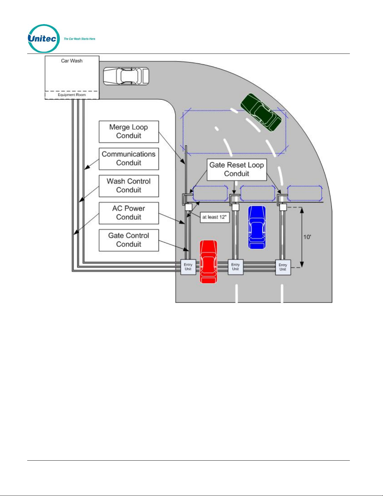
Figure 1. Example Multi-Lane Site Plan
Document Number: GC1004 2
Document Title: Unitec CAME Gate and Gate Controller Installation Guide
Page 7
Electrical Planning
Power Requirements
Each barrier gate requires a 115-120 VAC on a 5-Amp dedicated breaker, which should be provided
during wash construction. Most installers will have power supplied directly fr om one of the three phases
used to power the wash motors and controllers. If this method is used, special attention should be
given to proper grounding at the unit, as well as in the brea ker panel.
Note: Follow all local and national electrical codes!
Conduit Requirements
Plan your conduit runs so that the barrier gate control signal wiring and the loop wiring enter through
the bottom of the base of the gate. Figure 1 shows a typical sit e layout with the followin g conduit runs:
• A conduit between the AC service panel and the entry units for power wiring.
• A conduit between the entry units and gates for power wiring.
• A conduit between the gate controller (located in the equipment room) and the entry units
for control signal wiring.
• A conduit between the entry units and the gates for contro l signal wiring.
• Conduit between the gates and loops the loop leads.
Wiring Requirements
Wires to be pulled through the conduits are listed in the following tables. Wires should be 18
AWG (minimum) and color-coded to facilitate installation and troubleshooting. The quantities
shown are per lane.
Qty From To Function
3 AC Service Panel Gate Gate Power (115 VAC)
4 Gate Controller Entry Units Control wires
3 Gate Controller Gate Control wires
Loop Planning and Installation
General
Unitec provides 18-foot vehicle detection loops that can be used for the gate arm reset or merge
loops. Two loop types are available: direct burial and saw cut installation. Direct burial loops
Document Number: GC1004 3
Document Title: Unitec CAME Gate and Gate Controller Installation Guide
Page 8
would only be used in new construction (where concrete is not yet poured). Saw cut loops are
used in pre-existing concrete and installed in a rectangular groove that is cut into the concrete.
Refer to the loop installation instructions for detailed installation procedures.
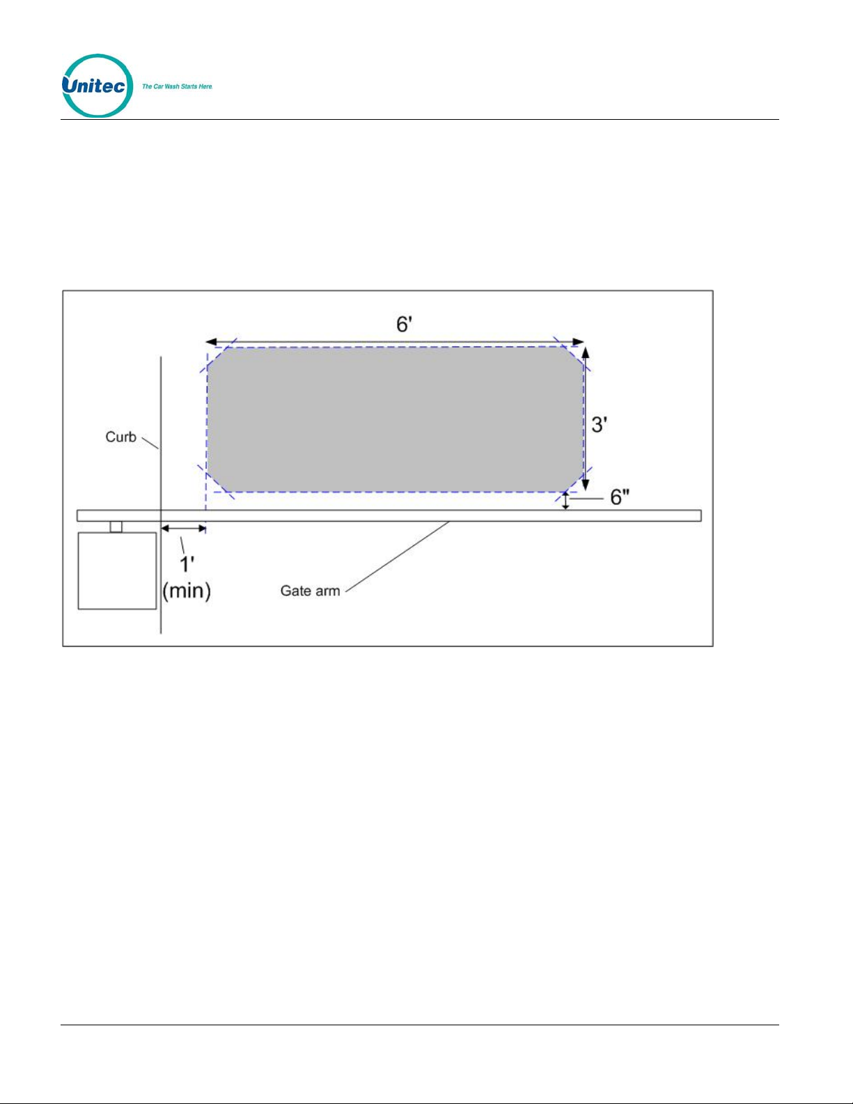
Gate Reset Loop
Each gate requires one gate reset loop. The reset loop should be formed into a 6’ long by 3’ wide
rectangle and located as shown in
Figure 2.
Figure 2. Gate Reset Loop Dimensions
Document Number: GC1004 4
Document Title: Unitec CAME Gate and Gate Controller Installation Guide
Page 9

Merge Loops
Merge loops are recommended to prevent vehicle queuing errors. These loops prevent a gate from
opening until all paid vehicles have merged into a single line at the tunnel en trance.
The number and size of loops required depends on the size of the merge zone area. The loop
detector in each gate has can accommodate (1) merge loop so the maximum number of merge loops
can not exceed the number of gates installed.
The front edge of a merge loop should be no more than 9 feet away from the back edge of the gate
reset loop to ensure proper detection of vehicles (see Figure 3). If the standard (18 foot) loop available
from Unitec is too small, larger loops can be provided as special orders.
Figure 3. Multi-Lane Merge Loop Placement
System Wiring
General
The payment system should be connected to the wash controller as described in its manual
except, the wash in use signal is not to be connected (as this signal is will be provided by the
gate controller). The following sections provide instructions on connecting the gate and gate
control power and the gate control signal wires.
Document Number: GC1004 5
Document Title: Unitec CAME Gate and Gate Controller Installation Guide
Page 10

Gate Controller Power
Warning:
Disconnect 115VAC-120VAC po wer from the m ain po wer lines at the
panel box before continuing!
The power connections are located at the bottom of the main terminal strip within the gate controller.
The Line, Neutral, and Ground (Earth) connections are labeled L, N, and E respectively.
Figure 4. Wire the AC Power to the Gate Controller
Document Number: GC1004 6
Document Title: Unitec CAME Gate and Gate Controller Installation Guide
Page 11

Gate Power
Connect the hot and neutral line to the red phoenix connector at the top of the gate, according the
installation manual included with the gate. Connect the ground wire to the cable lug on the base p late.
Figure 5. Gate Power
Document Number: GC1004 7
Document Title: Unitec CAME Gate and Gate Controller Installation Guide
Page 12

Gate to Gate Controller Wiring
Figure 6. Came Gate to Gate Controller Co nnections
There are 3 control wires that run from the gate to the gate controller. The gate reset loop and merge
loop wiring (if applicable) is also illustrated, above. You must remove the loop detector block to access
the block base for connecting the loop wires. The connections for each gate to the gate controller are
illustrated on the left sides of Figures 7 and 8.
Control Signal Wiring
There will be (4) control wires connected to each entry unit and (3) wires for each gate. For Portal and
Sentinel entry units, the control wires will terminate at connectors J3 and J18 on the Wash I/O board.
For the Wash Select II, the wires connect to J18 and J19 of the CPU board. The connections from the
gate controller to the gate are illustrated on the right sid e of Figures 7 and 8.
Figures 7 and 8 show controller wiring for up to four entry units and four gates. For installations with
fewer lanes, simply refer to the parts of the diagrams labeled for the numbers of units and gates you
are installing on site.
Document Number: GC1004 8
Document Title: Unitec CAME Gate and Gate Controller Installation Guide
Page 13

Figure 7. WSII to Gate Controller to Gate Connections
Document Number: GC1004 9
Document Title: Unitec CAME Gate and Gate Controller Installation Guide
Page 14

Figure 8. Portal/Sentinel to Gate Controller to Gate Connections
Document Number: GC1004 10
Document Title: Unitec CAME Gate and Gate Controller Installation Guide
Page 15

Configuration settings
Portal/Sentinel Settings
To configure the Portal or Sentinel, login to the Sierra Management Application then follow this
path to navigate to the configuration screen:
Setup>Device Profiles>(Edit next to device)>Wash Interface
Figure 9. Wash Interface Screen
1.
Enter the appropriate information in the following fields:
• Wash-in-Use Handshaking – Select this option when using a gate.
• Relay Latching –This needs to be unchecked if an entry gate is being used in conjunction
with the Portal or Sentinel.
• Fault OOS Detection – Check this box if a fault signal is available from the wash
equipment.
• Auto OOS Detection – Check this box to activate the Portal or Sentinel’s monitoring of the
out of service inputs from the wash.
• Relay Stacking –This needs to be checked if an entry gate is being used in conjunction
with the Portal.
Document Number: GC1004 11
Document Title: Unitec CAME Gate and Gate Controller Installation Guide
Page 16

• Start Button (over conveyor) – Used for Tunnel applications. This needs to be “off” if an
entry gate is being used in conjunction with the Portal.
Click OK to save your changes and return to the Bay Setup screen.
Wash Select II Settings
Before a Wash Select II (WSII) unit will operate with the Gate Controller, some configuration settings on
the Wash Select II must be changed. Refer to the WSII Operations Manual, Section 2.8.8: Wash
Interface Settings Tunnel mode for more information.
You must enable the Barrier gate interface of the WSII in order for the WSII to communicate with the
gate controller.
Figure 10. Wash Select II CPU Board
1.
Using the toggle switch at the top of the CPU board, place the Wash Select II in setup
mode by moving the switch toward the back of the Wash Select II case. (The CPU board is
located on the inside right wall of the Wash Se lect II case .)
2. On the WSII keypad, use the (3) key to scroll forward and the (1) key to scroll back. Scroll
through the main menu until the “Wash Interface” option is displayed. Press the (*) key to
enter.
3. Scroll through this menu until the “Barrier Gate” option is displayed, and then press the (*)
key to enter.
4. Press the (1) button to enable the option.
Document Number: GC1004 12
Document Title: Unitec CAME Gate and Gate Controller Installation Guide
Page 17

Depending on the interface of your WSII to the tunnel controller, you may need to put the WSII into
“Attended Tunnel Mode”
When the Tunnel Mode is set to “Attended,” each customer will receive a receipt to give to the
attendant, who will then arm the appropriate wash. For an interface to a Gate controller, you should
either use Roll Over or Attended mode. Do not use Mode 1 - Unattended mode.
1. Using the toggle switch at the top of the CPU board, place the Wash Select II in setup
mode by moving the switch toward the back of the Wash Select II case. (The CPU board is
located on the inside right wall of the Wash Se lect II case .)
2. On the WSII keypad, use the (3) key to scroll forward and the (1) key to scroll back. Scroll
through the main menu until the “Wash Interface” option is displayed. Press the (*) key to
enter.
3. Scroll through this menu until the “Tunnel Mode” option is displayed, and then press the (*)
key to enter.
4. Press the (2) button for “Attended Tunnel Mode” or (0) button to disable tunnel mode and
then press the (*) key.
Document Number: GC1004 13
Document Title: Unitec CAME Gate and Gate Controller Installation Guide
Page 18

System Test Procedure
The following section contains procedures for verifying the completed installation. The procedures are
written to cover up to 4 lanes of operation. Any lanes that do not have the wires connected will be
ignored by the Gate controller and do not need to be tested. The test procedure is to be performed in
lane sequence (i.e., test Lane 1, then Lane 2, etc.). If you chose to perform the procedures out of
sequence, follow the resetting of the entry unit power and Gate Controller as dictated in the init ia l step s
of testing for Lane 1.
Caution:
You may wish to do this test with the gate arms removed from the gates in order to
avoid damage to a vehicle if the Gate loops are malfu nctioning.
Testing System Interface for Lane 1
1. Reset power to all entry units.
2. Remove any vehicles below all gate loops and merge loop.
3. Verify that all Gates have power and the gates are down. Gates should be switched to
Automatic mode.
4. Reset Power to Gate controller. As you do, note the LCD screen display on it. It should
show the Gate controller software version then go to “Idle/Scanning.” The “Wash In Use”
output Y0,Y1,Y2,Y3 are the only output/input LEDs on the PLC that should be lit. They
provide the wash in use signal at each lane to hold the customer until the gate opens.
If this is not the case, check wiring of each terminal that is incorrect based on the Gate
Controller I/O Definitions chart in Section 5.
5. Verify that the “Wash In Use” LED on the associated board of the entry unit is lit. If not,
check the wiring from Y0/Terminals 41 and 11 to the entry unit.
6. Arm a wash at the entry unit in Lane 1.
7. Verify Gate at Lane 1 opens. If not, view the LCD screen on the PLC. If it shows
“IDLE/SCANNING” still, then it is not getting the signal into X0/terminal 21 from the entry
unit. Check the wiring from terminal 21 of the gate controller to the entry unit. If it shows
“Open Gate 1,” then check the wiring from the Gate Controller Y4/Terminal 51 to the Gate
terminal strip.
8. If everything is operating correctly, X4 LED on the PLC should be lit and the LCD screen
on the Gate controller should show “Wait for Gate 1”. If not, verify wiring from X4/Terminal
31 to the Gate terminal strip.
9. With the Gate for lane 1 open, drive a car through Lane 1. Validate that the Gate lowers after
the rear of the vehicle comfortably passes off the Gate Loop. If not, consult the Gate
Controller manual for Gate loop operation.
10. After the gate for Lane 1 closes, the LCD screen on the Gate controller should either show
“Car in Merge area” (if you have a Merge loop installed). Or “Idle/Scanning”
Document Number: GC1004 14
Document Title: Unitec CAME Gate and Gate Controller Installation Guide
Page 19

11. If you have connected the wash arming signals to your Tunnel controller, you should verify a
wash has been queued. If not, verify these connections.
Testing for Lane 1 is complete.
Testing System Interface for Lane 2
1. Remove any vehicles below all gate loops and merge loop.
2. Verify that all Gates have power and the gates are down. Gates should be switched to
Automatic mode.
3. Verify the “Wash In Use” LED is lit at the entry unit. If not, check the wiring from Y1/Terminals
42 and 11 to entry unit.
4. Arm a wash at the entry unit in Lane 2.
5. Verify Gate at Lane 2 opens. If not, view the LCD screen on the PLC. If it shows
“IDLE/SCANNING” still, then it is not getting the signal into X1/terminal 22 from the entry unit.
Check your wiring from terminal 22 of the Gate Controller to the entry unit. If it shows “Open
Gate 2” then check the wiring from the Gate Controller Y5/Terminal 52 to the Gate terminal
strip.
6. If everything is operating correctly, X5 LED on the PLC should be lit and the LCD on the Gate
controller should show “Wait for Gate 2”. If not, verify wiring from X5/Terminal 32 to the Gate
terminal strip.
7. With the Gate for lane 2 open, drive a car through Lane 2. Validate that the Gate lowers after
the rear of the vehicle comfortably passes off the Gate Loop. If not consult the Gate Controller
manual for Gate loop operation.
8. After the gate for Lane 2 closes, the LCD screen on the Gate controller should either show
“Car in Merge area” (if you have a Merge loop installed). Or “Idle/Scanning”
9. If you have connected the wash arming signals to your Tunnel controller, you should verify a
wash has been queued. If not, verify connections from the entry unit to the Tunnel controller.
Testing for Lane 2 is complete.
Testing System Interface for Lane 3
1. Remove any vehicles below all gate loops and merge loop.
2. Verify that all Gates have power and the gates are down. Gates should be switched to
Automatic mode.
3. Verify that the “Wash In Use” LED is lit at the entry unit. If not, check the wiring from
Y2/Terminals 43 and 11 to the entry unit.
4. Arm a wash at the entry unit in Lane 3.
5. Verify Gate at Lane 3 opens. If not, view the LCD screen on the PLC. If it shows
“IDLE/SCANNING” still, then it is not getting the signal into X2/terminal 23 from the entry unit.
Check your wiring from terminal 23 of the Gate Controller to the entry unit. If it shows “Open
Gate 3” then check the wiring from the Gate Controller Y6/Terminal 53 to the Gate terminal
strip.
Document Number: GC1004 15
Document Title: Unitec CAME Gate and Gate Controller Installation Guide
Page 20

6. If everything is operating correctly, X6 LED on the PLC should be lit and the LCD screen on
the Gate controller should show “Wait for Gate 3”. If not, verify wiring from X6/Terminal 33 to
the Gate terminal strip.
7. With the Gate for lane 3 open, drive a car through Lane 3. Validate that the Gate lowers after
the rear of the vehicle comfortably passes off the Gate Loop.
8. After the gate for Lane 3 closes, the LCD screen on the Gate controller should either show
“Car in Merge area” (if you have a Merge loop installed). Or “Idle/Scanning”
9. If you have connected the wash arming signals to your Tunnel controller, you should verify a
wash has been queued. If not, verify from the entry unit to the Tunnel controller.
Testing for Lane 3 is complete.
Testing System Interface for Lane 4
1. Remove any vehicles below all gate loops and merge loop.
2. Verify that all Gates have power and the gates are down. Gates should be switched to
Automatic mode.
3. Verify that the “Wash In Use” LED is lit at the entry unit. If not, check the wiring from
Y4/Terminals 44 and 11 of the Gate controller to the entry unit.
4. Arm a wash at the entry unit in Lane 4.
5. Verify Gate at Lane 4 opens. If not, view the LCD screen on the PLC. If it shows
“IDLE/SCANNING” still, then it is not getting the signal into X3/terminal 24 from the entry unit.
Check your wiring from the Gate Controller to the entry unit. If it shows “Open Gate 4” then
check the wiring from the Gate Controller Y7/Terminal 54 to the Gate terminal strip.
6. If everything is operating correctly, X7 LED on the PLC should be lit and the LCD screen on
the Gate controller should show “Wait for Gate 4”. If not, verify wiring from X7/Terminal 34 to
the Gate terminal strip.
7. With the Gate for lane 4 open, drive a car through Lane 4. Validate that the Gate lowers after
the rear of the vehicle comfortably passes off the Gate Loop.
8. After the gate for Lane 4 closes, the LCD screen on the Gate controller should either show
“Car in Merge area” (if you have a Merge loop installed). Or “Idle/Scanning”
9. If you have connected the wash arming signals to your Tunnel controller, you should verify a
wash has been queued. If not, verify connections from the entry unit to the Tunnel controller.
Testing for Lane 4 is complete.
Test for Merge Area
Using a vehicle, drive a small vehicle in all areas of the merge area, Verify that there are no dead zones.
Verify that in all areas, the PLC LCD shows “Car in Merge Area”. If not, determine if the issue is one of
the following:
• A merge loop signal from one of the gates is not functioning or being sent to Terminal 35.
• The merge area is not covered by merge loops completely.
Document Number: GC1004 16
Document Title: Unitec CAME Gate and Gate Controller Installation Guide
Page 21

[THIS PAGE INTENTIONALLY LEFT BLANK]
Document Number: GC1004 17
Document Title: Unitec CAME Gate and Gate Controller Installation Guide
Page 22

Gate Controller I/O Definitions
The following information is provided for troubleshooting purposes.
Table 1. Gate Controller I/O Definitions
Gate
Control
Signal name
Lane 1
Request
Lane 2
Request
Lane 3
Request
Lane 4
Gate
Control
Terminal
Number
21 X0 Input from Lane
22 X1 Input from Lane
23 X2 Input from Lane
24 X3 Input from Lane4
Gate
Control
PLC I/O
point
Device
Connection
1
2
3
Request
Gate 1 Open 31 X4 Input from Gate
1 Lockout
Gate 2 Open 32 X5 Input from Gate
2 Lockout
Gate 3 Open 33 X6 Input from Gate
3 Lockout
Gate 4 Open 34 X7 Input from Gate
4 Lockout
Merge Loop 35 X10 Input from one or
more merge
Loops from
Gates 1-4
Descriptive Use or
Operation
Terminal at lane 1 will hold this line at
24VDC when a customer at Lane 1
has purchased a wash. Terminal will
remove signal when Lane 1 Hold
turns off.
Terminal at lane 2 will hold this line at
24VDC when a customer at Lane 2
has purchased a wash. Terminal will
remove signal when Lane 1 Hold
turns off.
Terminal at lane 3 will hold this line at
24VDC when a customer at Lane 31
has purchased a wash. Terminal will
remove signal when Lane 1 Hold
turns off.
Terminal at lane 4 will hold this line at
24VDC when a customer at Lane 4
has purchased a wash. Terminal will
remove signal when Lane 1 Hold
turns off.
24VDC is present on this line when
Gate for Lane 1 is Open or Opening
24VDC is present on this line when
Gate for Lane 2 is Open or Opening
24VDC is present on this line when
Gate for Lane 3 is Open or Opening
24VDC is present on this line when
Gate for Lane 4 is Open or Opening
24VDC is present when any of the
merge loops from Gates 1-4 is active.
No gates will initiate an Open if a
Merge Loop is active.
Document Number: GC1004 18
Document Title: Unitec CAME Gate and Gate Controller Installation Guide
Page 23

Gate
Control
Signal name
Lane 1 Wash
in Use
Gate
Control
Terminal
Number
41 Y0 Output to Wash
Gate
Control
PLC I/O
point
Device
Connection
in use signal for
Lane 1
Lane 2 Wash
in Use
42 Y1 Output to Wash
in use signal for
Lane 2
Lane 3 Wash
in Use
43 Y2 Output to Wash
in use signal for
Lane 3
Lane 4 Wash
in Use
44 Y3 Output to Wash
in use signal for
Lane 4
Open Gate 1 51 Y4 Output to Vend
Input of Gate at
Lane 1
Open Gate 2 52 Y5 Output to Vend
Input of Gate at
Lane 2
Descriptive Use or
Operation
24VDC- is present when Gate
Controller is commanding Terminal at
Lane 1 to hold its current customer.
Signal turns off when Terminal is to
send customer through and fire wash
into queue. Note: This is a sinking
output. When testing, reference from
terminal 11(RED) to Y0. When Y0
light is on, Terminal 41(Black) to
11(Red) should measure 24VDC
24VDC- is present when Gate
Controller is commanding Terminal at
Lane 2 to hold its current customer.
Signal turns off when Terminal is to
send customer through and fire wash
into queue. Note: This is a sinking
output. When testing, reference from
terminal 11(RED) to Y1. When Y1
light is on, Terminal 42(Black) to
11(Red) should measure 24VDC
24VDC- is present when Gate
Controller is commanding Terminal at
Lane 3 to hold its current customer.
Signal turns off when Terminal is to
send customer through and fire wash
into queue. Note: This is a sinking
output. When testing, reference from
terminal 11(RED) to Y2. When Y2
light is on, Terminal 43(Black) to
11(Red) should measure 24VDC
24VDC- is present when Gate
Controller is commanding Terminal at
Lane 4 to hold its current customer.
Signal turns off when Terminal is to
send customer through and fire wash
into queue. Note: This is a sinking
output. When testing, reference from
terminal 11(RED) to Y3. When Y3
light is on, Terminal 44(Black) to
11(Red) should measure 24VDC
Tied to the Vend input of the Gate,
This line will become 24VDC- when
Gate 1 is triggered to open. Note:
This is a sinking output. When
testing, reference from terminal
11(RED) to Y4. When Y4 light is on,
Terminal 51(Black) to 11(Red) should
measure 24VDC
Tied to the Vend input of the Gate,
This line will become 24VDC when
Gate 2 is triggered to open. Note:
This is a sinking output. When
testing, reference from terminal
11(RED) to Y5. When Y5 light is on,
Terminal 52(Black) to 11(Red) should
measure 24VDC
Document Number: GC1004 19
Document Title: Unitec CAME Gate and Gate Controller Installation Guide
Page 24

Gate
Control
Signal name
Gate
Control
Terminal
Number
Gate
Control
PLC I/O
point
Device
Connection
Open Gate 3 53 Y6 Output to Vend
Input of Gate at
Lane 3
Open Gate 4 54 Y7 Output to Vend
Input of Gate at
Lane 4
Ground G N/A N/A
115V Line L N/A N/A
115V Neutral N N/A N/A
115V fused 5 N/A N/A
24VDC
6 N/A N/A
Regulated
24VDC Fused
F2 + N/A
for PLC
24VDC
Ground
24VDC Fused
10 -, C0, C1,
N/A
C0, C1
11 V+ N/A
for External
Descriptive Use or
Operation
Tied to the Vend input of the Gate,
This line will become 24VDC when
Gate 3is triggered to open. Note: This
is a sinking output. When testing,
reference from terminal 11(RED) to
Y6. When Y6 light is on, Terminal
53(Black) to 11(Red) should measure
24VDC
Tied to the Vend input of the Gate,
This line will become 24VDC when
Gate 4 is triggered to open. Note:
This is a sinking output. When
testing, reference from terminal
11(RED) to Y7. When Y7 light is on,
Terminal 54(Black) to 11(Red) should
measure 24VDC
Electrical Ground
115V Line (Hot)
115V Neutral (Common
Fused input power
Unfused 24VDC out of regulated PS
Fused power for PLC
Ground (24VDC-) for PLC power and
communications signals
Fused 24VDC signal power for
communications signals
Document Number: GC1004 20
Document Title: Unitec CAME Gate and Gate Controller Installation Guide
 Loading...