

Page 1
UTD2000CEX-II Series
Digital oscilloscope
User Manual
Page 2

Table of contents
General safety overview-------------------------------------------------------------- 2
Safety terms and symbols 3
Chapter 1 - Introduction guide 4
1.1 General check 4
1.2 Before use 4
1.3 Front panel introduction 5
1.4 Back panel introduction 6
1.5 Overview of operation panel function 6
1.6 User interface 9
Chapter 2 -Vertical channel setting 9
2.1 pen / activate / close analog channel 9
2.2 Channel coupling 10
2.3 Bandwidth limit 10
2.4 voltage /division 10
2.5 Probe 10
2.6 Reversed phase 10
Chapter 3 - Trigger system setting 10
3.1 rigger system interpretation 10
3.2 Edge trigger 11
3.3 Pulse trigger 12
3.4 Video trigger 13
3.5 Slope trigger 14
3.6 Under amplitude trigger 15
3.7 Over amplitude trigger 16
-----------------------------------------------------------
-----------------------------------------------------
--------------------------------------------------------------------
--------------------------------------------------------------------------
---------------------------------------------------------
---------------------------------------------------------
----------------------------------------
----------------------------------------------------------------------
-----------------------------------------------
----------------------------------------
----------------------------------------------------------------
-------------------------------------------------------------------
------------------------------------------------------------------
-------------------------------------------------------------------------------
-----------------------------------------------------------------
----------------------------------------------
---------------------------------------------------
-----------------------------------------------------------------------
----------------------------------------------------------------------
----------------------------------------------------------------------
----------------------------------------------------------------------
-------------------------------------------------------
---------------------------------------------------------
Chapter 4 - Horizontal system setting------------------------------------------ 17
4.1 ROLL scroll mode--------------------------------------------------------------- 17
4.2 Windows extensions------------------------------------------------------------ 17
4.3 Independent Time Base------------------------------------------------------- 18
Chapter 5 - Mathematical operation--------------------------------------------- 18
5.1 Mathematical function---------------------------------------------------------- 18
5.2 FFT--------------------------------------------------------------------------------- 19
5.3 Logical operation---------------------------------------------------------------- 20
Chapter 6 -Sampling system setting-------------------------------------------- 21
6.1 Sampling rate--------------------------------------------------------------------- 21
6.2 Acquisition type------------------------------------------------------------------- 22
6.3 Storage depth-------------------------------------------------------------------- 23
Chapter 7 - Display system setting --------------------------------------------- 23
7.1 XY Mode--------------------------------------------------------------------------- 24
7.2 Application of XY model-------------------------------------------------------- 24
Chapter 8 - Automatic measurement--------------------------------------------25
8.1 All parameters measurement------------------------------------------------- 26
8.2 Voltage parameter--------------------------------------------------------------- 27
8.3 Time parameter------------------------------------------------------------------ 27
8.4 Delay parameter----------------------------------------------------------------- 27
8.5 User defined parameters------------------------------------------------------ 27
Chapter 9 - Cursor measurement------------------------------------------------ 28
9.1 Time measurement------------------------------------------------------------- 28
Page 3

9.2 Voltage measurement 28
Chapter 10 - Storage and callback
10.1 Set up storage and callback 29
10.2 Waveform storage and callback 29
10.3 Screen copy 30
Chapter 11 - Auxiliary function setting
11.1 Waveform recording 31
11.2 Pass test 31
11.3 System upgrade 32
Chapter 12 - Other function key 36
12.1 Auto setup 36
12.3 Factory setting 36
Chapter 13 - System prompt and troubleshooting
13.1 System prompt information explaination 37
13.2 Troubleshooting 38
Chapter 14 - Technical specification
Chapter 15 - Appendix 42
Appendix A: Accessories and options 42
Appendix B: Maintenance 42
Appendix C: Warranty overview 43
Appendix D: Contact us 43
---------------------------------------------------------
---------------------------------------------- 29
------------------------------------------------
-------------------------------------------
--------------------------------------------------------------------
---------------------------------------- 30
----------------------------------------------------------
-------------------------------------------------------------------------
---------------------------------------------------------------
11.4 waveform record---------------------------------------------------------------33
11.5 AUTO strategy---------------------------------------------------------------- 34
11.6 Recorder ------------------------------------------------------------------------ 35
11.7 Waveform generator---------------------------------------------------------- 35
11.8 System Upgrade--------------------------------------------------------------- 35
-------------------------------------------------
----------------------------------------------------------------------
12.2 Run/Stop------------------------------------------------------------------------ 36
-----------------------------------------------------------------
------------------------ 37
--------------------------------
---------------------------------------------------------------
------------------------------------------- 38
--------------------------------------------------------------
------------------------------------------
---------------------------------------------------------
-------------------------------------------------
------------------------------------------------------------
Page 4

PREFACE
Dear Users:
Hello! Thank you for choosing this brand new UNI-T device. In order to safely and correctly use this instrument .please read this manual thoroughly, especially
the Safety Notes part. After reading this manual, it is recommended to keep the manual at an easily accessible place, preferably close to the device, for future
reference.
Copyright Information
UNl-T Uni-Trend Technology (China) Limited. All rights reserved.
Trademark Information
UNI-T is the registered trademark of Uni-Trend Technology (China) Limited.
Document Version
UTD2000CEX-II-20170422-V2.00
Statement
UNI-T products are protected by patent rights in China and foreign countries, including issued and pending patents.
UNI-T reserves the rights to any product specification and pricing changes.
UNI-T reserves all rights. Licensed software products are properties of Uni-Trend and its subsidiaries or suppliers, which are protected by national copyright
laws and international treaty provisions.
Information in this manual supercedes all previously published versions.
Warranty
UNI-T will guarantee that the product will be free from defects for a three-year period. If the product is re-sold, the warranty period will be from the date of the
original purchase from an authorized UNI-T distributor. Probes, other accessories, and fuses are not included in this warranty. If the product is proved defective
within the warranty period, UNI-T reserves the rights to either repair the defective product without charging of parts and labor, or exchange the defected product
to a wor king e quival ent pr oduct. Repla cemen t parts and pr oducts may be brand new, or pe rform a t the s ame spe cific ation s as bra nd new products. All
replacement parts, modules, and products become the property of UNI-T.
The “customer” refers to the individual or entity that is declared in the guarantee. In order to obtain the warranty service, "customer" must inform the defects
within the applicable warranty period to UNI-T, and to perform appropriate arrangements for the warranty service. The customer shall be responsible for packing
and shipping the defective products to the designated maintenance center of UNI-T, pay the shipping cost, and provide a copy of the purchase receipt of the
original purchaser. If the product is shipped domestically to the location of the UNI-T service center, UNI-T shall pay the return shipping fee. If the product is
sent to any other location, the customer shall be responsible for all shipping, duties, taxes, and any other expenses.
This warranty shall not apply to any defects or damages caused by accidental, machine parts’ wear and tear, improper use, and improper or lack of maintenance.
UNI-T under the provisions of this warranty has no obligation to provide the following services:
UTD2000CEX-II User Manual
Page 5

a) Any repair damage caused by the installation, repair, or maintenance of the product by non UNI-T service representatives.
b) Any repair damage caused by improper use or connection to an incompatible device.
c) Any damage or malfunction caused by the use of a power source that does not conform to the requirements of this manual.
d) Any maintenance on altered or integrated products (if such alteration or integration leads to an increase in time or difficulty of product maintenance).
This warranty written by UNI-T for this product, and it is used to substitute any other express or implied warranties. UNI-T and its distributors do not offer any
implied warranties for merchantability or applicability purposes.
For violation of this guarantee, UNI-T is responsible for the repair or replacement of defective products is the only remedy available to customers. Regardless
of whether UNI-T and its distributors are informed that any indirect, special, incidental, or consequential damage may occur, UNI-T and its distributors shall not
be responsible for any of the damages.
General Safety Overview
This instrument strictly complies with the safety requirements for electronic measuring instrument GB4793 and IEC 61010-1 safety standard during design and
manufacturing. Please understand the following safety preventative measures, to avoid personal injury, and to prevent damage to the product or any connected
products. To avoid possible dangers, be sure to use this product in accordance with the regulations.
Only trained personnel can perform the maintenance program.
Use the correct power line: Only use the dedicated UNI-T power supply appointed to the local region or country for this product.
Correct Plug: Don't plug when the probe or test wire is connected to the voltage source.。
Ground the product: This product is grounded through the power supply ground wire. To avoid electric shock, grounding conductors must be connected to
the ground. Please be sure that the product is properly grounded before connecting to the input or output of the product.
Correct connection of oscilloscope probe: Ensure that the probe ground and ground potential are correctly connected. Do not connect ground wire to high voltage.
Check all terminal ratings: To avoid fire and the large current charge, please check all the ratings and the marks on the product. Please also refer to the
product manual for details on the ratings before connecting to the product.
Do not open the case cover or front panel during operation。
Only use fuses with ratings listed in the technical index
Avoid circuit exposure: Do not touch exposed connectors and components after power is connected.
Do not operate the product if you suspect it is faulty, and please contact UNI-T authorized service personnel for inspection. Any maintenance, adjustment,
or replacement of parts must be performed by UNI-T authorized maintenance personnel.
Maintain proper ventilation
Please do not operate the product in humid conditions
Please do not operate in inflammable and explosive environment
Please keep the product surface clean and dr
UTD2000CEX-II User Manual
Page 6

Safety Terms and Symbols
The following terms may appear in this manual:
Warning: The conditions and behaviors may endanger life.
Note: The conditions and behaviors may cause damage to the product
and other properties.
The following terms may appear on the product:
Danger: Performing this operation may cause immediate damage to the
operator.
Warning: This operation may cause potential damage to the operator.
Note: Th is oper ation m ay cause damage to the p roduct and dev ices
connected to the product.
The following symbols may appear on the product:
Perface
This man ual des cribes the ope ration o f the UT D2000C EX-II s eries digital
oscillo scope . T he manu al incl udes the follow ing sec tions:
Chapter 1 Intro ductio n Guide
Chapter 2 Vertical channe l setting
Chapter 3 Trigger s ystem s etting
Chapter 4 Horiz ontal s ystem setting
Chapter 5 Mathe matica l operation
Chapter 6 Sampl ing sys tem setting
Chapter 7 Displ ay syst em setting
Chapter 8 Automati c measu rement
Chapter 9 Curso r measu rement
Chapter 10 Stor age and callba ck
Chapter 11 Auxiliary fu nction setting
Chapter 12 Othe r funct ion keys
Chapter 13 Syst em prom pt and troubles hootin g
Chapter 14 Technical sp ecific ation
Chapter 15 Appendi x
UTD2000CEX-II User Manual
Page 7

Brief introduction of UTD2000CEX-II series digital phosphor
oscilloscope
1) UTD2000CEX-II series digital oscilloscope contains the following 2 models
UTD2102CEX-II
UTD2072CEX-II
Model
Analog channel number
Analog bandwidth
2) UTD2000CEX-II series digital oscilloscope is based on UNI-T’s unique Ultra
Phosphor technology. A multi-functional, high performance oscilloscope
tha t is easy to u se, w ith exc elle nt t echnica l sp ecif ica tions, a per fect
combination of many functionalities that can help users to quickly conduct
testing. UTD20 00CEX-II series is aimed at satisfying the most e xtensive
os cil los co pe m ark et s, i ncl udi ng com mun ic ati ons , s emi con duc to rs,
computers, aerospace de fense, instr umentation, industrial electronics ,
consumer electron ics, automotive el ectronics, field maintenance, R&D,
education, etc.
3) Main features of UTD2000CEX-II series digital oscilloscope:
● Configure 100MHz/70MHz two levels bandwidth, providing two channels
for each model
● The highest real-time sampling rate: 1GS/s, can capture the faster signal
● Standard storage depth of 25kpts.
● Waveform capture rate of up to 30,000wfms/s
● Wav eform uni nt err up ted recor din g s upp or ts u p t o 80 00 w av efo rm s
● 8 inches WVGA (800 * 480) TFT LCD, ultra wide screen, vivid color, clear
display
● Ab undan t t ri gg er fe at ur es, inclu di ng a v ar ie ty of advan ced tr ig ge r
● Standard configuration interface: USB-OTG, Pass/Fail (pass / fail)
● Automatic measurement of 34 waveform parameters
● Support USB disk storage and software upgrades via USB disk, one key
copy screen capture function
● Su pp ort Pl ug a nd Pla y U SB dev ic es, an d ca n u se U SB inter fa ce t o
communicate with the computer
Chapter 1 – Introduction Guide
This chapter introduces on using the oscilloscope for the first time, the front
and rear panels, the user interface, as well as the built-in help system.
1.1General Inspection
It is recommended to follow the steps below before using the UTD2000CEX-II
series for the first time.
1.1.1 Check for Damages caused by Transport
If the packaging carton or the foam plastic cushions are severely damaged,
please contact the UNI-T distributor of this product immediately.
1.1.2 Check attachments
Please check Appendix A for the list of accessories. If any of the accessories
are missing or damaged, please contact UNI-T or l ocal distr ibutors of t his
product.
1.1.3 Machine Inspection
If the instrument appears to be damaged, not working properly, or has failed
the functionality test, please contact UNI-T or local distributors of this product.
If the equipment is damaged due to shipping, please keep the packaging and
notify both the transportation department and UNI-T distributors, UNI-T will
arrange maintenance or replacement.
1.2 Before Use
To perform a quick verification of the instrument’s normal operations, please
follow the steps below:
1.2.1 Connect to the Power Supply
The power supply voltage range is from 100 VAC to 240 VAC, the frequency
range is 45Hz to 440Hz. Connect the oscilloscope to the power supply line
that came with the oscilloscope or any power supply line that meets the host
country standards. Turn the power button on the back of the oscilloscope to
ON. Now the soft power button in the front of the oscilloscope should be lit
green.
UTD2000CEX-II User Manual
Page 8
1.2.2Boot Check
Press the soft power button and the light should change to yellow. The
oscillo scope th en will show a bo ot anim ation, a nd it will enter the norm al
interface afterwards.
1.2.3Basic Function Check
After the oscilloscope enters the normal interface, find the button at the
bottom right of the operation panel. Long press button to hear the voice
of the relay switch, and then press the button, the screen will automatically
complete the signal condition, 1kHz ,3Vpp square wave signal appears on
the sc re en . Pr es s th e k ey ag ain , t he n th e i nt er nal re fe ren ce in pu t is
disconnected, the channel can be in a normal external input state.
1.2.4Probe Compensation
When the probe is connected to any input channel for the first time, this step
might be required in order to match the probe and the input channel. Please
follow the following steps:
① Set the attenuation coefficient in the probe menu and the switch on the
probe to 1 0x, and co nnect the p robe to CH 1. Make su re the probe’s c
onnector is properly connected with the oscilloscope. Connect the probe’s
main clip and gr ound cli p to the o scillos cope’s ca librati on and g round
terminal respectively. Open CH1 and press the button.
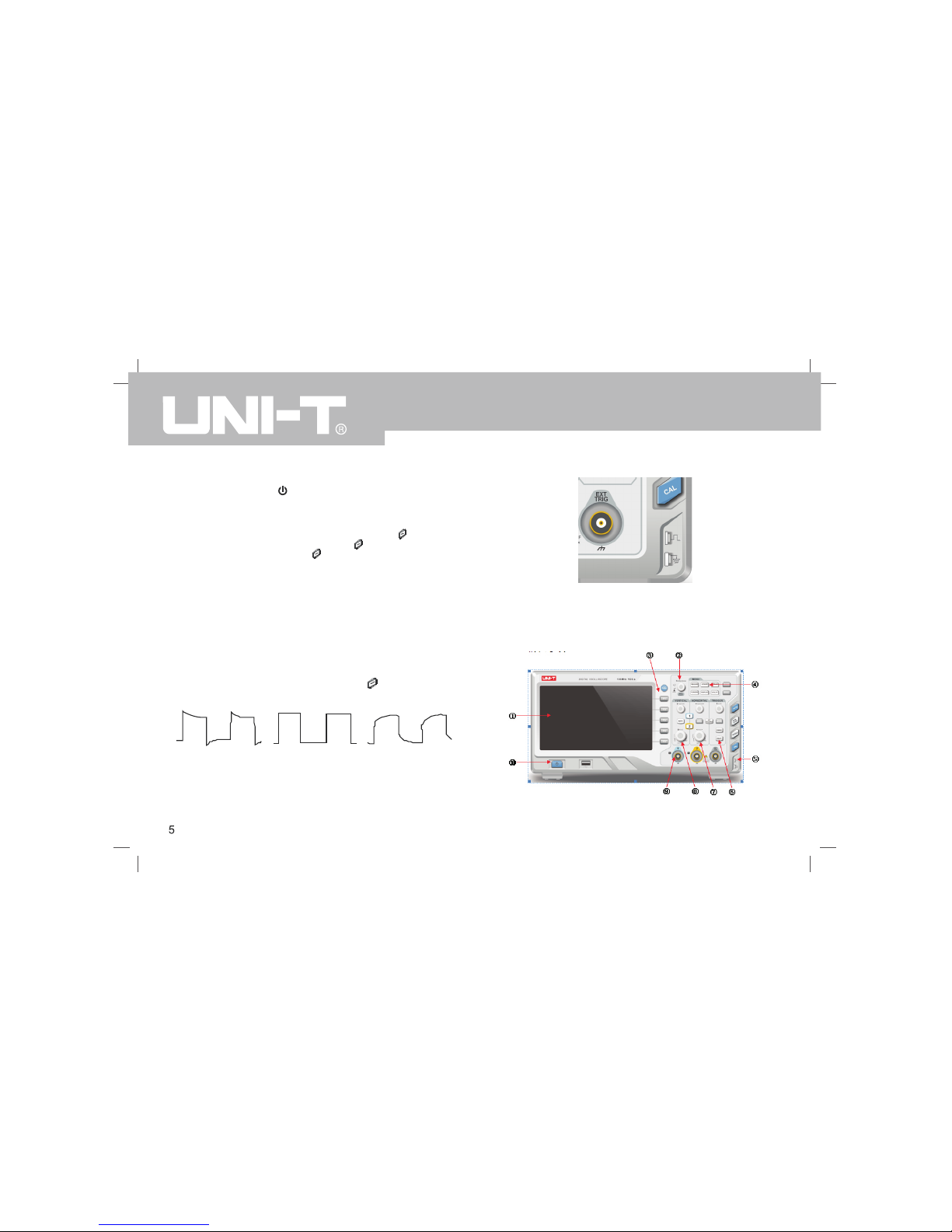
② Observed waveforms
Excessive Compensation Correct Compensation Insufficient Compensation
③ If the displayed waveform does not look like the above “correct
compensation” waveform, use a non-metallic screwdriver to adjust the
probe’s variable capacitance until the display matches the "correct
compensation" waveform.
Warning: To avoid electric s hock when me asuring hig h voltage us ing the
probe, please ensure that the probe insulation is in good condition and avoid
physical contact with any metallic part of the probe.
1.3Front panel introduction
Front panel
UTD2000CEX-II User Manual
Page 9
①.Screen display area
②. Multifunction knob
③. Function menu key
④. Control menu softkey.
⑤. Probe compensation signal connecting piece and grounding
⑥. Trigger control area.
⑦. Horizontal control area.
⑧. Vertical control area.
⑨. Analog channel input.
⑩. Power soft key
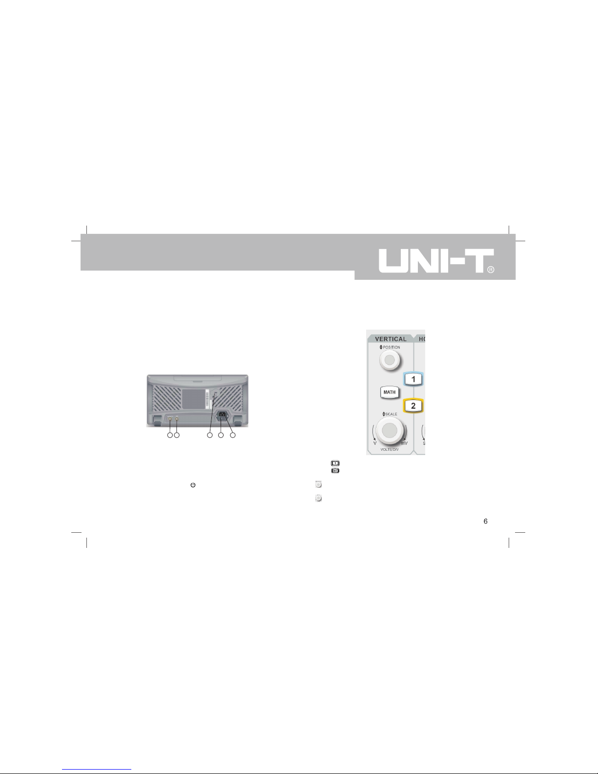
1.4 Back panel introduction
1 2
3
4
5
Back panel
①.Pass/Fail:Pass/fail test output, also supports Trig_out output
②. AWG:This model does not support
③. Security lock: you can use the security lock (sold separately)
Oscilloscope can be locked in a fixed position through the key hole .
④. Power Switch: after the AC socket is connected to the power supply, turn
on the Power Switch. Press the button on the front panel to Power On.
⑤. AC power input socket : AC power input port . Use the power cord supplied
within the accessory package to connect the oscilloscope to the AC power
supply (the power supply for the oscilloscope to require is 100 to 240 V,
50Hz/60Hz).
1.5 Operation Panels
This section describes the front panel operations to help users to quickly
familiarize with the UTD2000CEX-II series.
(1)Vertical Control
①.Press buttom to open or close the two channels display.
②. Press buttom to open the mathematical operations menu for add,
subtract, multiply, divide, FFT, filtering, logic, and advanced operations.
③. Vertical Position Knob: Used to adjust the vertical position of the current
channel waveform.
④. Vertical Scale Knob: Used to adjust the vertical scale of the current
waveform. The vertical scale has 1, 2, and 5 steps.
UTD2000CEX-II User Manual
Page 10
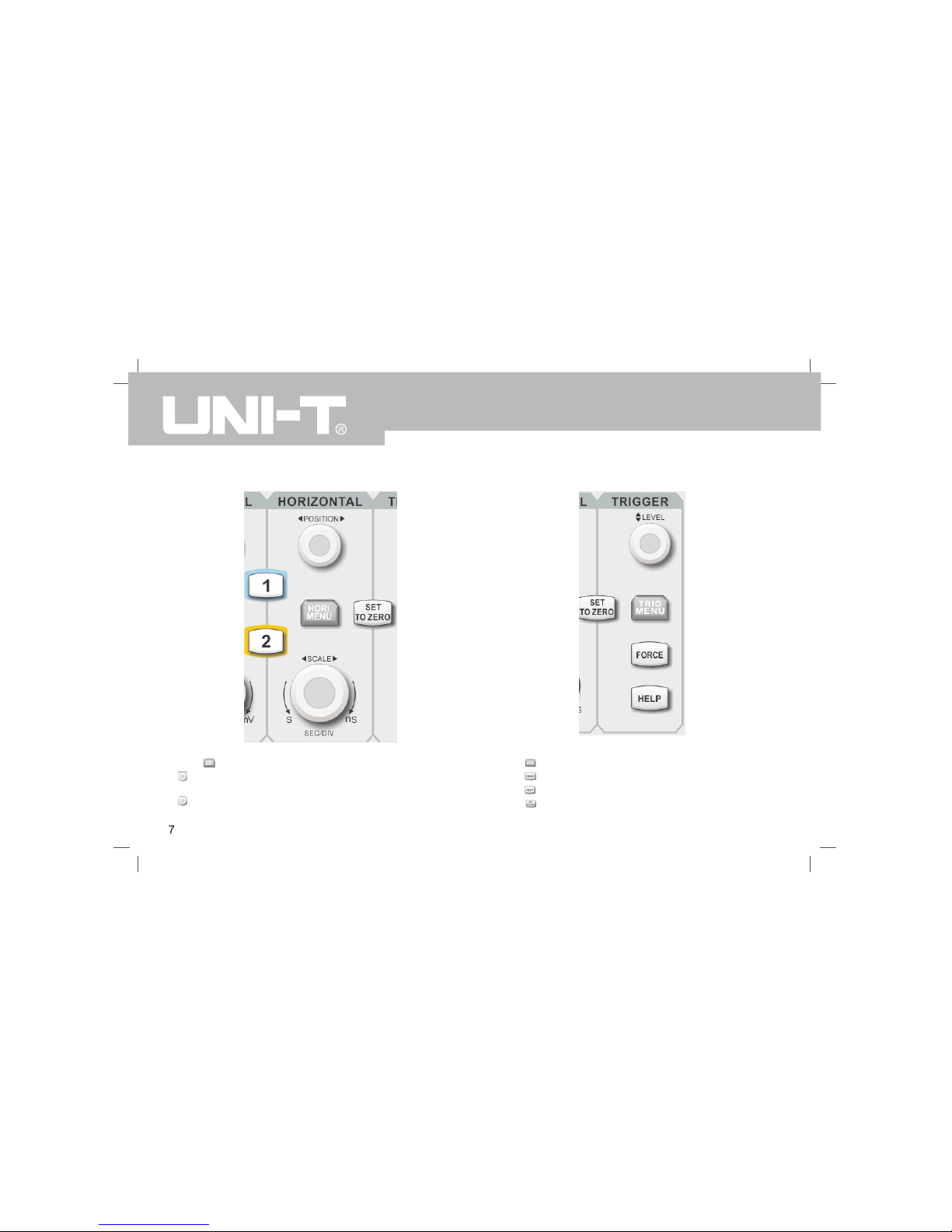
(2) Le ve l Con tr ol
①.Press buttom to display wind ow extension a nd holdoff time.
②. Horizonta l Position Knob:used t o adjust the horizonta l position of
the current channel waveform.
③. Horizontal Scale Knob:used to adjust the vertical scale of the current
waveform. The vertical scale has 1, 2, and 5 steps.
(3) Tri gg er Co nt rol
① Trigger Level Knob:used to adjust the currently selected trigger level.
② Press to pop-up the trigger menu.
③ Press to force generate a single trigger event .
④ Press to display the built-in help information .
⑤ Press to center the trigger level, trigger position, and channel position
simultaneously.
UTD2000CEX-II User Manual
Page 11

( ) Aut o Se tti ng4
When this ke y is presse d, the oscil loscope wi ll automatically adju st the
vertical sc ale factor, time base, and t rigger mode according to the inpu t
signals.
(5). Run/S top
Press the k ey to "run" or "stop" sa mpling. RU N state is in dicated by
green light . STOP state is indicated b y red light .
(6). Singl e trigg er
Press this k ey to set up single trig ger mode.
(7).Correction signal switching
Long press the key to drive the cor rection si gnal to enter or leave t he
channel
(8).Screen copy
Press this key to quickly copy the screen wav eform to the USB storag e
device in BM P bitmap form at
(9).Multipurpose Knob
Multipurpo se: During menu operat ions , turn the knob to s elect subm enu,
then press t he knob to c onfirm the o ptions .
(10).Function Keys
①. Measure se tting key: can set meas ure source to all param eters,
custom par ameters and perform me asurement statistics, select
measureme nt indicat ors, etc.
②. Sampling setting key: set up acquisition mode and the storage depth .
③. Stor age in terface key: can se lect di fferen t type s for st orage and
waveform, which can be stored int ernally or through USB device.
④. Curs or m eas ure men t ke y : c an m easu re w ave for m’s time and
voltage ma nually wit h cursor.
⑤. Display set ting key : used f or the display settings such a s display
type, form at, duration, grid bri ghtness, a nd waveform brightnes s.
⑥. The utility key : can be used to choose some less commonly used
settings s uch as self-calibrati on, system information, languag e, menu
display, waveform recording, pass test, square wave output, frequency
meter, system up grades, ba cklight br ightness, o utput, etc .
⑦. Press th is key to res tore to fac tory default settings .
⑧. Press th is key to ope n the wavef orm recording menu.
UTD2000CEX-II User Manual
Page 12
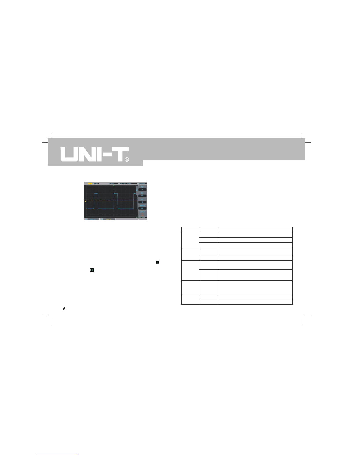
1.6 User interface
Dis play in terfa ce
①.Trigger status identific ation: inc lude TRIGED , AUTO, READY, STOP,
and ROLL
②. Indicates the amount of time represented by one square, which can be
adjusted by the horizontal scale knob.
③. Shows the horizonta l displace ment, whic h can be adj usted by tu rning
the horizontal position knob.
④. Displays trigger source, type, slope, coupling, level, etc.
a. Trigger Source: they are CH1, CH2, AC Line, EXT,etc.
b Trigger types : edge, pulse width, video, slope, etc..
c Trigger slope: rising, falling, and rising/falling. For example, is rising..
d Trigger coupling: DC, AC, high frequency, low frequency and noise. .
For example, is DC coupling.
⑤. Hardware frequency meter: display the frequency information of current
channel.
⑥. USB d evice Identific ation : This i con wi ll be d ispla yed when an USB
storage device is connected.
⑦. Channel vertical status Identification: Displays channel activation state,
channel coupling, bandwidth limit, vertical profile, and probe attenuation
coefficient.
⑧. Sampling Rate/A cquisiti on Mode: I ndicates the current sampl ing rate
and storage depth.
Chapter 2 -Vertical Channel Setting
2.1 Open / activate / close analog channel
CH1~CH2 contains 3 states: open, activate, and shut down.
Open: Allows the corresponding channel waveform to be displayed on the
screen.
Activate: Only opened state can be activated. In the active state,the vertical
menu and the vertical control knobs (POSITION, SCALE) are available for
changing activated channel setting. Any of the channels that has been opened
but not be en activ ated coul d be acti vated by p erssing the correspondin g
channel keys
Shut down : No waveform appears on the display.
The table below describes the channel menu:
Description
Pass AC and DC components of the input signal
Pass AC part of input signal only
Displays ground signal
Turns off bandwidth limit function
Limits bandwidth to 20MHz to reduce the noise.
The vertical sensitivity of the current
channel can be set to 1, 2, and 5 order.
Set Fine Adjustment to be within the coarse
range. Set the channel’s vertical sensitivity
with 1% of the current amplitude value.
A value is automatically selected according
to the probe’s attenuation coefficient, to
ensure consistency between the vertical
profile readout and the displayed waveform.
Normal waveform display
Reverse waveform
Options
DC
AC
Ground
Full
bandwidth
20M
Coarse
Adjustment
Fine
Adjustment
Off
On
Functions
Coupling
Bandwidth
Limitation
Vertical
Sensitivity
Probe
Reverse
Phase
UTD2000CEX-II User Manual
Page 13

Chapter 3 - Trigger System Setting
Trigger determines when the oscilloscope starts to collect data and displays
waveform. Once the trigger is correctly set, it can convert unstable signals into
meaningful waveforms. In the beginning of data acquisition, it collects enough
data to compose the wave form starting at the lef t of the trigger point, and
continues until the trigger condition is met.
3.1 Trigger System Interpretation
(1)Trigger Source
Trigger Source : a signal to be used to generate a trigger.
Triggers can be obtained from a variety of sources such as input channels
(CH1, CH2), external trigger (EXT), Line AC, alternate trigger, etc.
■ Input channel: Select any one of the analog signal input terminal (CH1,CH2)
on the front panel of the oscilloscope as a trigger signal.
■ External trigger: Select the input Trig EXT from the back of the oscilloscope.
For example, the external clock input can be used on the Trig EXT terminal
as a trigger source. EXT signal trigger level ranges from –3V~ +3V which
can be set.
■ AC Line:Power supply signal, used to observe the relationship between
power signals such as lighting equipment and power supply equipment, to
obtain stable synchronization.
■ Alternate trigger: automatically turn on the independent time base after being
selected .
(2) Trigger Mode
This oscilloscope provides three kinds of trigger modes: Auto trigger, Normal
trigger, and Single trigger
■ Auto trigger: When there is no trigger signal, the system automatically runs
and displays data. When the trigger signal is generated, it automatically switch
to trigger scanning and signal synchronization.
2.2 Channel Coupling
Using CH1 as an example, when a signal is connected to CH1 and activated,
press F1 and select channel coupling via the multipurpose knob. You can also
switch to channel coupling by continuously pressing the F1 key. Press the
multipurpose knob to confirm selection.
2.3 Bandwidth Limitation
When bandwidth limitation is open, the bandwidth of the oscilloscope is limited
to about 20MHz, and attenuates any signal above 20MHz. It is commonly used
to reduce the high frequency noise . When the bandwidth limit function is on,
the BW logo will appear in the vertical state identification
2.4 Vertical Sensitivity
The vertical sensitivity is divided into coarse and fine adjustments.
In coarse adjustment, the sensitivity range is from 1mV/div ~ 20V/div, with
1 – 2 – 5 order.
For example: 10mV - >20mV - >50mV - >100mV
In fine adjustment, it is adjusted with 1% of the current amplitude value .
For example:10.00mV—>10.10mV—>10.20mV—>10.30mV
Note: div means square of the display area , one div(square) stands for one grid
2.5 Probe
In order to set the attenuation coefficient of the probe, the coefficient needs to
be set up in the channel operation menu. If the probe attenuation coefficient is
10:1, the probe coefficient should then be set to 10X to ensure correct voltage
reading.
The coefficients can be set to 0.001X, 0.01X, 0.1X, 1X, 10X, 100X, and 1000X
with 1 – 2 – 5 order.
2.6 Reverse Phase
When reverse phase is turned on, the waveform flips 180 degrees. A reverse
phase logo will appear in the vertical state identification
UTD2000CEX-II User Manual
Page 14

Note: This mode allows 50ms/div or slower time shift without triggering in ROLL
mode.
■ Normal trigger: The oscilloscope can only collect data when the trigger condition
is satisfied. When it is not triggered, the oscilloscope will wait for the triggered
signal.
■ Single triggle : When the user presses the "run" button, the oscilloscope will
wait for the trigger. When the instrument detects a trigger, the waveform is
sampled and displayed, and enters the STOP state. Press the SINGLE button
on the front panel of the oscilloscope to quickly enter the single trigger mode.
(3) Trigger Coupling
Trigger coupling determines which part of the signal will be transmitted to the
trigger circuit. The coupled type includes DC, AC, low frequency, high frequency
suppression, and noise suppression.
■ DC:Pass all components of the signal
■ AC: Blocks the DC component and attenuates any signal components below
10Hz.
■ High frequency suppression: Attenuates high frequency components over
1MHz.
■ Low frequency suppression: Blocks the DC component and attenuates low
frequency components below 680 kHz.
■ Noise suppression: Suppress high frequency noise in the signal, and reduces
probability of error.
(4) Trigger Sensitivity
The minimum signal required to generate a correct trigger. For example, normally
the input channel (CH1~CH2) trigger sensitivity is 1div, which means the signal
should be at least 1 div.
(5) Pre-Trigger / Delayed Trigger
Data collected before / after the Trigger event.
Trigger position is usually set at the level center of the screen, and you can
observe 7 grids of pre-trigger and delay trigger information. The horizontal
displacement of the wave can be adjusted by the horizontal displacement
position knob in order to observe more pre-trigger information.
(6) Forced Trigger
Press the FORCE key to generate a forced trigger signal.
If the waveform is not displayed in normal mode or single shot mode, press
the FORCE button to collect signal baseline to ensure the acquisition is normal.
3.2 Edge Trigger
The signal can be triggered by the rising or falling edge.
Press the TRIG MENU to enter the trigger menu. Press F1 to select the trigger
type, and select the edge trigger mode with the multipurpose knob.
The edge trigger menu descriptions :
Options
Edge
CH1, CH2
EXT
AC Line
Alternate trigger
fall
Rise/fall
DC
AC
Functions
Type
Sources
Descriptions
Set any one of the CH1,CH2 as a trigger signal
Set external trigger as the source
Set AC line as trigger
Set CH1, CH2 as alternate trigger source
Set the falling edge as the trigger signal
Set the rising and falling edge as the trigger signal
Pass all components of the signal
Blocks the DC components of the signal
UTD2000CEX-II User Manual
Page 15

Trigger
Coupling
Trigger
Mode
Slope
Suppression of signal frequency above 1.23MHz
Suppression of signal frequency below 680kHz
Suppress the noise of the trigger signal,
trigger sensitivity is halved.
When the signal input is not triggered, the
system automatically collects the waveform
data and displays the scan baseline on the
screen. When a trigger signal is generated,
it automatically turns to the trigger scan.
The data acquisition stops when the
signal is not triggered.
Generates a trigger , and then stops
Set the rising edge of the signal as trigger
Set the falling edge of the signal as trigger
Set the rising and falling edge of
the signa as trigger
High frequency
suppression
Low frequency
suppression
Noise
suppression
Auto
Normal
Single
Rise
Fall
Rise/fall
3.3 Pulse Width Trigger
Pulse width trigger can set the capture condition through the pulse width.
Press the TRIG MENU button to enter the trigger menu. Press F1 to select trigger
type, and select the Pulse Width Trigger mode with using the Multipurpose knob.
The pulse width trigger setting menu (1) :
Options
Pulse Width
CH1, CH2
EXT
AC Line
DC
AC
High frequency
suppression
Low frequency
suppression
Noise
suppression
Auto
Normal
Single
Functions
Type
Sources
Trigger
Coupling
Trigger
Mode
Pulse
Width
Setting
Next Page
Descriptions
Set any one of the CH1,CH2
as the trigger source
Set external trigger as the trigger source
Set AC line as the trigger source
Pass all components of the signal
Blocks the DC components of the signal
Suppression of signal frequency
above 1.23MHz
Suppression of signal
frequency below 680kHz
Suppress the noise of the trigger signal,
trigger sensitivity is halved.
When the signal input is not triggered, the
system automatically collects the waveform
data and displays the scan baseline on the
screen. When a trigger signal is generated,
it automatically turns to the trigger scan.
The data acquisition stops when the
signal is not triggered.
Generates a trigger , and then stops
Enter settings page
Enter Trigger Setting Menu (2)
UTD2000CEX-II User Manual
Page 16

The pulse wi dth trigger setting me nu (2) :
Descriptio ns
Set positiv e pulse as t rigger sign al
Set negativ e pulse as t rigger sign al
Triggered when the pulse w idth
is greater t han the set ting time
Triggered when the pulse w idth
is samller t han the set ting time
Triggered when the pulse w idth
is equal to t he setting time
The pulse wi dth time ca n be set from
20.0ns~10. 0s by using the
Multipurpo se knob
Options
Pulse Width
Positive
Negative
>
<
=
20.0ns~10. 0s
Functions
Type
Pulse Width
Polarity
Pulse Width
Condition
Pulse Width
Setting
Pulse Width : The time diff erence betw een the tri gger level of the posit ive
pulse is def ined as the positive pu lse width, and the time difference
between the trigger le vel of the ne gative pul se is defin ed as the neg ative
pulse width , as shown i n the follow ing diagra m.
Positive
Negative
3.4 Video Trigger
The waveform of t he video signal i ncludes the imag e signal and the time
sequ enc e sig nal , and eac h ki nd of sig nal u ses diff ere nt st and ards and
formats. UPO2000CEX-II provides the basic measurement functions,
which can be triggered in NTSC, PAL, and other standard video formats.
Press the T RIG M ENU, Pres s F1 t o sel ect t he tr igger type, s et to vide o
trigger mod e with usin g the Multip urpose kno b.
The video tr igger menu descriptio ns :
Descriptions
Set any one of the CH1,CH2 as trigger source
Uses PAL format video signals
Uses NTSC format video signals
Set the video to sync and trigger on even field
Set the video to sync and trigger on odd field
Set the video to sync and trigger on all lines
Set the video to sync and trigger on specific lines
When video sync is set at specific lines, using
the multipurpose knob can adjust the number
of lines: For PAL/SECAM: 1~625 lines.
For NTSC: 1~525 lines
Options
Video
CH1, CH2
PAL
NTSC
Even field
Odd field
All lines
Specific lines
Functions
Type
Source
rmat
Video
Sync
Specific
Lines
UTD2000CEX-II User Manual
Page 17

Video Line Sync
Video Field Sync
3.5 Slope Trigger
When slope t rigger is s elected, tr igger occu rs when the rising or fa lling
slope value matches th e value in se ttings.
Press the TRIG MENU, pres s F1 to sele ct the trigg er type, se lect slope
trigger mod e with usin g the Multip urpose kno b.
Slope Trigger Menu
Descriptio ns
Set any one of the Ch1,
CH2 as trigger source
Pass all components of the signal
Blocks the DC components of the signal
Suppression of signal
frequency above 1.23MHz
Suppression of signal
frequency below 680kHz
Suppress the noise of the trigger
signal, trigger sensitivity is halved.
When the signal input is not triggered,
the system automatically collects the
waveform data and displays the scan
baseline on the screen. When a trigger
signal is generated, it automatically
turns to the trigger scan.
The data acquisition stops
when the signal is not triggered.
Generates a trigger, and then stops
Enters slope setting menu
Options
Slope
CH1, CH2
DC
AC
High freque ncy
suppressio n
Low frequen cy
suppressio n
Noise
suppressio n
Auto
Normal
Single
Functions
Type
Sources
Trigger
Coupling
Trigger
Mode
Slope
Setting
UTD2000CEX-II User Manual
Page 18

Slope Setti ng Menu
Descriptions
Triggers with falling slope
Triggers with rising slope
When slew rate setting is smaller
than signal slew rate, trigger occurs
When slew rate setting is greater
than signal slew rate, trigger occurs
When slew rate setting is equal
to signal slew rate, trigger occurs
Pulse width can be set in
20.0ns~10.0s range, Use the
multipurpose knob to set time,
The slope of the low threshold level
can be adjusted with the LEVEL knob
The slope of the high threshold level
can be adjusted with the LEVEL knob
The slope of the high and low threshold
level can be adjusted with the LEVEL knob
Options
Falling
Rising
=
20.0ns ~10.0s
Low
High
High and Low
Functions
Slope
Condition
Time
Setting
Threshold
3.6 Under-r ange Trigger Trigger
The Un der-r ange Tri gger o ccurs when a pulse crosses ov er one trigg er
level but not over the other one. Press the TRIG MENU button to enter the
trig ger menu . Press F 1 to s ele ct tr igg er type a nd use th e Multip urpose
knob to sele ct Under-r ange Trigger mod e.
Under-rang e Trigger Menu (1 ):
Descriptions
Set any one of the Ch1,
CH2as a trigger signal
Pass all components of the signal
Blocks the DC components of the signal
Suppression of signal
frequency above 1.23MHz
Suppression of signal
frequency below 680kHz
Suppress the noise of the trigger
signal, trigger sensitivity is halved.
When the signal input is not triggered,
the system automatically collects the
waveform data and displays the scan
baseline on the screen. When a trigger
signal is generated, it automatically
turns to the trigger scan.
The data acquisition stops
when the signal is not triggered.
Generates a trigger, and then stops
Enters Under-range Trigger Menu (2)
Options
Under-range
CH1, CH2
DC
AC
High frequency
suppression
Low frequency
suppression
Noise
suppression
Auto
Normal
Single
Functions
Type
Sources
Trigger
Coupling
Trigger
Mode
Under-range
Setting
UTD2000CEX-II User Manual
Page 19

Descriptions
Set any one of the Ch1,
CH2as a trigger signal
Pass all components
of the signal
Blocks the DC components
of the signal
Suppression of signal
frequency above 1.23MHz
Suppression of signal
frequency below 680kHz
Suppress the noise of the trigger
signal, trigger sensitivity is halved.
When the signal input is not triggered,
the system automatically collects the
waveform data and displays the scan
baseline on the screen. When a trigger
signal is generated, it automatically
turns to the trigger scan.
The data acquisition stops when
the signal is not triggered.
Generates a trigger , and then stops
Enters Beyond-range Setting
Trigger Menu (2)
Options
Beyond-range
CH1, CH2
DC
AC
High frequency
suppression
Low frequency
suppression
Noise
suppression
Auto
Normal
Single
Functions
Type
Sources
Trigger
Coupling
Trigger
Mode
Beyond-range
Setting
Unde r-ran ge Trigg er Me nu ( 2)
Descriptio ns
Triggers when s et pulse wi dth is
less than un der-range width
Triggers when s et pulse wi dth is
greater tha n under-ra nge pulse wi dth
Triggers when s et pulse wi dth is
equal to und er-range p ulse width
Use the mult ipurpose k nob to set th e
pulse width time in 20. 0ns~10.0s r ange
Options
Positive Polarity
Negative Polarity
Irrelevant
<
>
=
20.0ns~10n s
Functions
Polarity
Condition
Time
Setting
The slope of the low thr eshold leve l
can be adjus ted with th e LEVEL knob
The slope of the high th reshold lev el
can be adjus ted with th e LEVEL knob
The slope of the high an d low thresh old
level can be adjusted w ith the LEVE L knob
Low
High
High and Low
Threshold
3.7 Beyond- range Trigger
When beyond-range trigger is selected, a high and a low trigger levels are
chosen. The trigger even t occurs wh en the input signal is h igher than the
high tigger level, or lower than the low trigger level. Press the TRIG MENU
button to ente r the trigger menu. P ress F 1 to sel ect tri gger t ype, us e the
Multipurpo se knob to s elect to bey ond-range mode.
Beyond-ran ge Trigger Menu ( 1):
UTD2000CEX-II User Manual
Page 20

Beyond-ran ge Setting Trigger Menu (2)
Options
Rise
Fall
Rise /Fall
Enter
Return
Time
20.0ns~10.0s
Low
High
High and Low
Functions
Slope type
Condition
Time setting
Trigger Level
Descriptions
Triggers when input signal
enters trigger level range
Triggers when input signal
leaves trigger level range
Triggers when time in trigger level
mode matches the set time
Using the multipurpose knob to set the
pulse width time in 20.0ns~10.0s range
The slope of the low threshold level can
be adjusted with the LEVEL knob
The slope of the high threshold level can
be adjusted with the LEVEL knob
The slope of the high and low threshold
level can be adjusted with the LEVEL knob
Chapter 4 - Horizontal System setting
4.1 ROLL mode
When the trigger is in automatic mode and using the SCALE knob to adjust
the horizontal level to slower than 50ms/div, and the oscilloscope will be in
ROLL mode. At this point, the trigger system will not work, the oscilloscope
will be continuous on the screen to draw the waveform of the voltage - time
chart.
ROLL Mode Waveform
4.2 Extended Window
Used to enlarge waveform,the extended waveform setting cannot be slower
than main waveform setting.
Extended Window display
UTD2000CEX-II User Manual
Page 21

Press the bu tton HORI MENU in the co ntrol pane l. Press F1 to select th e
Ext end ed Win do w . U nde r t he E xt end ed W in dow mo de, th e sc ree n i s
divided into two display areas as the above picture shows. The upper part
disp lays the orig ina l wav efo rms, whi ch ca n move le ft an d ri ght t hro ugh
rotatin g the kno b horizo ntal PO SITIONA L or can enl arge and reduce the
selected areas through rotating the knob horizontal SCALE. The lower part
displays the horizontal scale waveform. Note that scale time base improves
definition compare wi th the main t ime base (a s the above picture sho ws).
Because the waveforms displayed by the whole lower part are corresponding
to the areas selected by upper half part, rotating the knob horizontal SCALE
to reduce the selected areas can improve the scale time base, namely, can
improve the waveforms horizontal SCALE mult iple.
Note: The max scale time b ase is 200n s/div.
4.3 Trigger Release
Trigger releas e can obser ve complex w aveforms ( such as pulse series).
Relea se ti me is the ti me fo r the o scil losc ope to re-e nabl e the trigg er. In
the period of release and suppression, the oscilloscope will not be triggered.
For example, a set of pulse series, which is required to trigger on the first
pulse, can s et the rele ase time to t he pulse wi dth.
Pres s th e HOR I ME NU bu tto n to e nte r the lev el co ntr ol m enu. Use the
Multipurpo se knob to s elect trigg er release .
Chapter 5 - Mathematical Operation
UTD2000CEX -II series oscillosco pe carries a variety of mathemati cal
operations :
Ma th: So urc e 1+ sou rce 2, s our ce 1- s our ce2 , so urc e 1* sou rce 2,
source 1/ s ource2
FFT:Fast Fo urier Transform
Digital F ilter
Pres s the MATH b utto n to ente r the mat hema tic al op era tion men u.Th e
POS IT ION an d t he SCA LE kn obs ca n b e us ed to cha ng e t he v er ti cal
posi tio n an d the ver tic al p rofile o f th e ma the mati cal ope rat ions . Un der
mathematical operations, the horizonta l position cannot be indepe ndently
adjusted, it will change automatically according to the analog input channel
signals.
5.1 Mathema tical Function
Press MATH button, then press F1 to choose the type (m ath)
Math Menu
Descriptio ns
Set any one o f the Ch1,
CH2 as Math S ource 1
Source 1 + So urce 2
Source 1 - So urce 2
Source 1 * So urce 2
Source 1 / So urce 2
Set any one o f the CH1,
CH 2 as Math S ource 2
Options
Math
CH1, CH2,
+
-
*
/
Ch1 CH2,
Functions
Type
Source 1
Operator
Source 2
UTD2000CEX-II User Manual
Page 22

5.2 FFT
Using FFT (Fast Fourier Transform) mathe matical op erations, the time
domain sign al (YT) can be converte d into freq uency doma in signal. Th e
following t ypes of sig nals can be e asily obse rved with u sing FFT:
Harmonic co ntent and d istortion i n measurem ent system
Performan ce of noise in DC power s upply
Vibration Analys is
FFT frequen cy spectrum
Press MATH button, then press F1 to select FFT to enter t he FFT menu.
FFT menu
Descriptions
Set any one of the CH1,CH2 for FFT source
Use Hamming Window Function
Use Blackman Window Function
Use Rectangle Window Function
Use Hanning Window Function
Set vertical unit as linear or dB (log)
Options
FFT
CH1, CH2
Hamming
Blackman
Rectangle
Hanning
Vrms dBVrms,
Functions
Type
Source
Window
Vertical Unit
FFT Tips
Signals with DC components might cause mistakes or inaccuracies in FFT
calculation. In order to reduce e rror, it is adviced to set the channel to AC.
In order to reduce interference or noise from isolated events, the capture
mode can be s et to avera ge.
UTD2000CEX-II User Manual
Page 23

(1) Select Wi ndow Funct ion
UTD2000CEX -II series provides 4 k inds of com mon window functions:
Re cta ngl e : T he bes t f req uen cy res ol uti on a nd the wo rst amp li tud e
resolution are similar to the condition of no window , suitable for measuring
the follow ing wavefo rm:
a. Transien t or shor t pulse , the sig nal lev el is app roxima tely equ al to th e
before and after
b. Constant amplitude sine wave wi th similar frequency
c. random no ise with sl ow broadban d spectrum
Hanning:Compared with the rectangular window, it has better frequency
resolution, but less range. It is suitable for measuring sine, periodic and
narrow-ba nd random n oise.
Hamming:Slightly better in t he frequency resolution than the Hanning
window, suitable for measu ring trans ient or shor t pulse, la rge varian ce
of before a nd after signals.
Blackman: The best range resolution, the wo rst freque ncy resolution,
it can be used to me asur e the sing le fr eque ncy s igna l, to find higher
harmonics .
(2) Set Vertical Unit
Vertical units can be Vrms or dBVrms . Press F4 to select the desired un it.
Vrms and dBVrms show the vertical amplitude by means of logarithmic and
linear. To display the FFT spectrum in a larger dynamic range, dBVrms can
be used.
5.3 Digital Filter
Press MATH button, then press F1 to select digital fi lter to ente r the menu.
Digital Fil ter Menu
Descriptions
Set filter to low pass
Set filter to high pass
Set filter to band pass
Only valid in high pass or
band pass; Use Multipurpose
knob to modify lower limit value
Only valid in low pass or band
pass; Use Multipurpose knob
to modify upper limit value
Set any one of the Ch1,
CH2 for digital filter source
Independently adjust the
position of the filtered waveform
Independently adjust the
position of the filtered waveform
Options
Digital Filter
Low Pass
High Pass
Band Pass
CH1, Ch2
Functions
Type
Filter Type
Frequency
Lower Limit
Frequency
Upper Limit
Source
vertical
displacement
Horizontal
displacement
UTD2000CEX-II User Manual
Page 24

Digital Fil ter
Chapter 6 - Sampling System Setting
Sampling is taking ana log input an d converts into a disc rete points using
analo g to d igit al co nver ter ( ADC) . Pre ss th e ACQUI RE ke y to e nter the
sampling me nu.
Sampling me nu
In average sampling mode,use Multipurpose
knob to set average time, number can be in the
range of 2n, where n is 1~13 integer
Automatic storage depth
2~512
Auto
OFF
ON
Descriptions
Sampling in a normal manner
Sampling with peak detection
Sampling with a high resolution
Sampling in an average manner
Options
Normal
Peak
High
Resolution
Average
Functions
Sampling
Mode
Average
Storage
Depth
Fast
sampling
6.1 Samplin g Rate
(1) Samplin g and Sampl ing Rate
When the analog signal is sampled, the sample is then converted into digital
data. The digital data is collected as the waveform record , and the recorded
data is then stored in t he memory.
Analog Sing al Sampling Points
UTD2000CEX-II User Manual
Page 25

Sampling rate refers to the time interval between two sampling points. The
maximum sam pling rate is 1 GS/s.
The sam pling r ate wil l be affe cted b y the ti ming sc ale and the change of
storage dep th. UTD200 0CEX-II osc illoscope s sampling rate is disp layed in
real-time a t the top of the screen i n the statu s bar. The horizontal SCALE
knob can be used to adjust the horizontal timebase or modify the memory
depth.
(2) Low Samp ling Rate Effect
1.Waveform Distortion: Due to low sampling rate, the details of the waveform
mig ht be miss ing, the s ampl ing w avef orm migh t be d iffer ent t han the
actual sig nal
2.Wave Mi xing: When the sa mplin g rate is 2 ti mes lower t han th e actu al
signal frequency (Nyquist frequency), the frequency of the reconstructed
signal wil l be less th an the actua l signal fr equency.
3.Waveform Leakage: Due to low sampling rate, the reconstructed waveform
might not r eflect the actual sign al
6.2 Acquisitio n Mode
To obtain a waveform from sampling points, press the ACQUIRE key, then
press F1 key to switch the acquisit ion method s.
(1) Normal S ampling
In this acquisition mode, the signal is sampled and reconstructed with equal
time intervals. Fo r most waveforms, the use of this mode can produce the
best effect.
(2) Peak Sam pling
In this acquis ition m ode, th e maxim um and m inimum values of the input
signal are found at e ach sampling interval, and the wavefo rm is displayed
by using these values. This way, the oscilloscope can acquire and display
a narrow pulse, otherwise the narrow pulse might be missed in the normal
mode. Noise might be en larged in th is mode.
(3) High Res olution
In this acqu isition mo de, the osci lloscope c an reduce random noise from
the input si gnal and ge nerate smoo ther wavef orms.
High Resolu tion mode t o minimize n oise from s mall signa l
(4) Average
In this acquisi tion mode, the oscilloscope obtains sever al waveforms a nd
finds the average, and displays the final waveform. This method can reduce
random nois e.
Via changing the acquisition mode settings, the resulting waveform display
will be changed. The unaveraged and the 32 times averaged waveform are
displayed b elow for co mparison.
UTD2000CEX-II User Manual
Page 26

32X Averaged
Note: Average a nd hig h reso lutio n uses diffe rent a verag e meth ods. T he
former is multi ple sampling av erage, the latter is single sa mpling average .
Unaveraged
6.3 Storage Dep th
The stor age dep th is the number of wave forms th at can b e stored in the
oscil losco pe dur ing a t rigge r acquisit ion. I t refl ects t he mem ory st orage
capa cit y of the acq uis iti on. UTD 200 0CE X-I I se rie s’ st and ard is 2 5kp ts
storage depth (per ch annel).
Chapter 7 - Display System Setting
You can set the display type of the waveform, display format, duration, grid
brightness, and waveform brightness. Press the DISPLAY key to enter the
display menu.
Display menu
Descriptions
Display level on time scale
Display Lissajous graph
of CH1~CH2 waveforms
Using lines to display between samples
Displays points directly
waveform on screen refreshs
with normal refresh rate
The waveform data on the screen
refreshs after specified time
The waveform data on the screen is
maintained until the function is off
Set the waveform brightness, Use
Multipurpose knob to adjust settings
Options
YT
XY
Vector
Point
Full
Grid
Crosshair
Frame
Automatic
Short afterglow
Long afterglow
Infinite
persistence
1%~100%
Functions
Type
Format
grid
Afterglow
time
Waveform
Brightness
UTD2000CEX-II User Manual
Page 27

7.1 XY Mode
The XY mode display is als o called Li ssajous graph.
When XY 1&2 are selected, the CH1 signal will be entered on the horizontal
axis (X) , and the CH2 on t he verti cal axi s (Y). In X-Y mode , when CH 1 is
activated, use the horizontal POSITION knob to adjust the graph horizontally.
When CH2 is acti vated, use the h orizon tal POS ITION kn ob to ad just th e
graph vertically.The vertical SCALE knob to be used to adjust each channel’s
amplitude level. The horizontal SCALE knob can be used to adjust the time
position in order to ob tain a well d isplayed L issajous g raph.
XY Display Mode
7.2 Application of XY Mode
The phase difference between the two signals of the same
frequency can be easily observed by Lissajous method.
The fol lo win g ch ar t gi ve s th e ob se rva ti on o f ph as e
difference.
Since sinθ = A/B or C/D, theta (θ) is the angle between
the two signals, the definition of A, B and C, D is shown
above. We can draw a difference angle θ = ± arcsin(A/B)
or θ = ± arcsin(C/D). If the principal axis of an ellipse is
in quadrants I and III , then the phase angle should be
in I, IV quadrant, in 0 to (π / 2) or (3 π / 2) to 2 π. If the
principa l axis of a n ellipse in II, IV quadrant , then the
phase angle should be (π /2) to π or π to (3 π/2).
In addition, if the fr equency or phase difference of the
two detect ed signal s is an int eger, the freq uency and
the phase relationship between the two signals can be
calculated .
UTD2000CEX-II User Manual
Page 28

Chapter 8 - Automatic Measurement
UTD2000CEX -II series digital flu orescence oscillosc ope can auto matically
measu re up t o 34 pa rameters. Press the ME ASUR E butt on to e nter t he
automatic m easuremen t menu.
Automatic M easuremen t menu
Descriptio ns
Close all Pa rameters
Pop-up a fra me with all
parameters presentin g
Open/Close menu for us er defined
parameters . When it is on, define
all require d paramete rs with usin g
the Multipu rpose knob .
Real-time d ynamicall y indicates
measuremen t paramete rs
Enter advan ced measur ement menu
Turn off the feature
Automatic c alculatio n of user def ined
parameters of average , max, and mi n.
Only applic able when u ser defined
parameters are presen t.
Restart sta tistics
Clear all me asurement
Options
Off
On
On/Off
Off
Parameter 1 ~5
Off
On
Functions
All Parameters
User Defined
Indicator
Advanced
measurement
Measurement
statistics
Reset statistics
Clear
Advanced me asurement menu
Descriptions
Delay measurement
Phase measurement
FRR: time between the first rising edge of
source 1 and the first rising edge of source 2
FRF: time between the first rising edge of
source 1 and the first falling edge of source 2
FFR: time between the first falling edge of
source 1 and the first rising edge of source 2
FFF: time between the first falling edge of
source 1 and the first falling edge of source 2
LRF: time between the last rising edge of
source 1 and the last edge of source 2
LRR: time between the last rising edge of
source 1 and the last rising edge of source 2
LFR: time between the last falling edge of
source 1 and the last rising edge of source 2
LFF: time between the last falling edge of
source 1 and the last falling edge of source 2
Opt ions
Functions
Measuremen t
parameters
Source
edge
UTD2000CEX-II User Manual
Page 29

8.1 All Paramet ers Measur ement
Press th e MEASU RE butt on to ent er the a utomat ic meas urement menu.
Then press F1 to select the source of the measurement . Press F2 to select
all 34 param eters.
The color of measured p arameters i s consiste nt with the current cha nnel.
When "----" is shown, it indicates that the current source has no signal input,
or the measu rement res ult is not va lid (too bi g or too small).
all paramet ers displa y interface
8.2 Voltage parame ters
Voltage Parameter Diagram
Vmax: Voltage at t he highest p oint with respect to GN D
Vmin: Voltage at t he lowest po int with respect to GND
Vtop: Highe st stable vo ltage
Vbase: Lowe st stable vo ltage
Middle: Mid point betwe en highest and lowest stable volt age
Vpp: Vmax – V min
Vamp: Vtop – Vbase
Mean: Average amplitude of the waveform on scre en
CycMean: Average amplit ude of a wave form in one p eriod
RMS: The effec tive value. According to the energy produced by the AC
signal in th e conversio n, the equivalent ener gy that the D C voltage
correspond s to
CycRMS: The RMS of one period
Overshoot: The ratio of the difference between Vmax and Vtop
Preshoot: T he ratio of t he differenc e between Vm in and Vbase
Area: The pr oduct of tim e and voltag e for all poi nts on the sc reen
CycArea: Th e product of time and voltage for al l points in o ne period
UTD2000CEX-II User Manual
Page 30

8.3 Timing parameters
Period: The duration of one cycle o f a repetiti ve wavefor m
Frequency : The recipro cal of the p eriod
Rise time: The time it ta kes the wav eform ampli tude to inc rease from
10% to 90%
Fall time: The time it ta kes the wav eform ampli tude to dec rease from
90% to 10%
+Width: The width of a po sitive pul se at 50% amp litude
-Width: The width of a ne gative pul se at 50% amp litude
+Duty: The ratio of posi tive pulse width to per iod
-Duty: The ratio of nega tive pulse width to per iod
Timing Paramet er
8.4 Delay parameters
FRR: Time between the first rising edge of source 1 to the first rising
edge of source 2
FRF: Time between the first rising edge of source 1 to the first falling
edge of source 2
FFR: Time between the first falling edge of source 1 to the first rising
edge of source 2
FFF: Time between the first falling edge of source 1 to the first falling
edge of source 2
LRF: Time between the last rising edge of source 1 to the last falling
edge of source 2
LRR: Time between the last rising edge of source 1 to the last rising
edge of source 2
LFR: Time between the last falling edge of source 1 to the last rising
edge of source 2
LFF: Time between the last falling edge of source 1 to the last falling
edge of source 2
8.5 User defined parameters
Press the MEASURE button to enter the automatic measurement menu.
Takes the current activation channel as the source of measurement. The
user defined parameter selection interface can be chosen by F2.
User Defined Parameter Selection
Adjust the parameters with the multipurpose knob, press the Multipurpose
knob button to confirm selection. For every selected parameter, a * symbol
will app ear in fr ont of t he p aram ete r. Pre ss F2 to turn off user def ined
parameter selection menu and the parameters will be display at the bottom
of the screen. For convenien ce and immedia te view of th ese parameters,
up to 5 parameters can be defined at the same time.
UTD2000CEX-II User Manual
Page 31

Open the D-v alue measu rement stat istics aft er defining parameter
Chapter 9 - Cursor Measurement
The cursor c an be used t o measure th e X axis (ti me) and the Y axis
(voltage) o f the selec ted wavefor m. Press th e CURSOR button to ente r
the cursor m easuremen t menu.
9.1 Time Measurement
Press the CURSOR key to enter the cursor measurement menu, then press
F1 to select the type to time.
• Press F2 to set the pattern to inde pendent.
• The Multipurpose knob c an adjust t he vertical cursor AX, press the
multipurp ose knob to switch to cu rsor BX.
The measure d values ar e shown in th e upper lef t corner of the wavefor m
display are a. The value o f BX-AX is t he time measurement, a nd 1/|BX-AX|
is the recip rocal of ti me.
For a period ic signal, if AX and BX are se t at the risi ng edge of a djacent
cycles, the n BX-AX is the signal’s p eriod, and 1/|BX-AX| i s the frequency.
The voltage value can a lso be displ ayed at cur sor’s cur rent posit ion. That
is AY, BY, and BY-AY.The M ultipurpo se knob can be used to ad just the BX
and AX positions when settin g is set to t race mode wi th using th e F2 key.
9.2 Voltage Measur ement
• The me thod for vo ltage meas ureme nt is simil ar to the me thod f or ti me
measurement, only that the vertical cursor becomes the horizontal cursor.
• Press th e CUR SOR k ey to ente r the curs or me asur emen t men u, th en
press F1 to select the type as volt age.
• Press F2 to set the pattern to inde pendent
The Multipu rpose knob can be used t o adjust th e horizontal cursor AY on
the screen, press the M ultipurpose knob to s witch to cursor BY. The value
of BY-AY is the voltage measurement (V). W hen the setting is set to trace
mode with using the F2 key, the Multipurpose knob can adjust both AY and
BY at the same time.
UTD2000CEX-II User Manual
Page 32

On the upper left corner of the display area, BY and AY are represented by
the current posi tion of the curs or BY and AY respectively. BY-AY indicates
the voltage difference b etween the two cursors.
Chapter 10 - Storage and Callback
With the sto rage function, you can save the os cilloscope's setting s,
waveforms, and screen imagees to t he oscillo scope's internal or ex ternal
USB storage devices, and recall the saved settings or waveforms anytime.
Press the STORAGE key to e nter the st orage funct ion settin g interface.
UTD2000CEX-II series oscilloscope supports FAT format USB storage devices.
It is not com patible wi th NTFS form at.
10.1 Storag e Setting and Callback
Press STORAGE button, then press F1 to select the type of settings, then
to enter the storage me nu
Settings fo r the storage menu.
Descriptions
Data will be saved on the oscilloscope
Data will be saved on USB drive
Saves settings to selected disk
Call back previously saved settings,
returns the oscilloscope to the
previously saved setting state
Options
Storage Setting
CH1,CH2
DSO
USB
Functions
Type
Source
Disk
Save
Callback
Remarks
Oscillos cope can only select US B device wh en U disk or o ther exter nal
storage de vices are p lugged in.
Callback only works when previo usly saved disk and the file name a re
consisten t, or else it will fail t o load.
10.2 Waveform S torage and Callback
Press the STORAGE button , then pres s F1 to set th e type of wa veform ,
then to ente r waveform storage men u.
Waveform stora ge menu.
Descriptions
Select waveform storage source
from any one of CH1,CH2
When Save is pressed, waveform
will be saved to the oscilloscope
When Save is pressed, waveform
will be saved to external USB device
Saves the waveform to selected disk
Enter the REF menu for the details
Options
Waveform Storage
CH1, CH2
DSO
USB
Functions
Type
Source
Disk
Save
Callback
UTD2000CEX-II User Manual
Page 33

After the waveform is saved, you can use the REF key for callback. Press
the REF key t o enter the waveform ca llback men u.
Waveform Callb ack Menu
Descriptions
When Save key is pressed, waveform
will be saved to the oscilloscope
When Save key is pressed, waveform
will be saved to external USB device
Callback previously saved
waveform and display on screen
Close current REF waveform
Options
RefA、RefB
DSO
USB
Functions
Type
Disk
Callback
Clear
After callb ack, the Re f waveform w ill be disp layed in the lower left corner,
inclu ding timi ng sc ale a nd am plitude sh ift. At this poin t you can u se the
vertica l and hor izontal contro l knob to adjust t he ref w aveform ’s positi on,
time base, a nd amplitu de shift.
10.3 Screen Copy
The Prt Sc key can be used t o stor e the cu rrent scree n in BM P forma t to
an external USB storage device. Th e bit map c an be open ed di rect ly on
the PC. This function can only be used when external USB storage devices
are connect ed.
Chapter 11- Auxiliary Function Setting
Press the UT ILITY key to e nter the au xiliary fun ction sett ings menu.
Auxiliary f unction se tting menu ( 1)
Descriptions
Enter system configuration page
Enter interface configuration page
Enter pass test page
Enter wave record page
Enters Auxiliary function setting menu (2)
Functions
System configuration
Interface configuration
Pass test
Wave record
1/3
Options
Auxiliary f unction se ttings menu (2)
Descriptions
Enter AUTO strategy page
Enters Auxiliary function setting menu (3)
Functions
Measuremen t unit
AUTO strategy
2/3
Options
V/A
Note: The frequency mete r is a count er for trigg er events. The frequenc y
meter is val id for edge or pulse wid th, but is n ot valid for the other t rigger
type .
Auxiliary f unction se ttings menu (3)
Descriptions
Enter recorder page
Enter waveform generator page
Set up frequency of reference
waveform
Enter oscilloscope software
update page
1Hz/10Hz/100Hz/
1kHz/10kHz/100kHz
Functions
Recorder
waveform generator
Square wave output
System Upgrade
Options
UTD2000CEX-II User Manual
Page 34

11.1 System configuration
System conf iguration menu (1)
Descriptions
press the Select key to start
the self calibration
prompting the system name and version
press the Select key to clean up
Enter time setup page
Enter next page
Functions
Self calibration
System information
Clean information
Time setup
Next page
Options
System conf iguration menu (2)
Descriptions
pop-up default dialog box,
press the select key to start
Use Multipurpose to adjust the
screen contrast ratio, Max 100
Select whether to open the screen
saver, if opened, the screen will be
closed when the set - time arrives,
Press any key to restore.
Return UTILITY root directory
Functions
Factory settings
Contrast ratio
Screen protection
Return
Close
1 minute
5 minutes
10 minutes
30 Minutes
Options
Time menu setting
Descriptio ns
Control dis play
Selected vi a the F2 but ton, use
Multipurpo se key to ad just
Selected vi a the F3 but ton, use
Multipurpo se key to ad just
Selected vi a the F4 but ton, use
Multipurpo se key to ad just
Make the mod ification to be valid
Functions
Time display
Minute &hou r
Date&month
Year
Confirm
Options
On/Off
11.2 interface configuration
Descriptio ns
Control the display /h ide
time of the s ide bar men u
Use Multipu rpose key t o
modify the d isplay bri ghtness
of the grid, the highes t 32
Options
Simplified Chinese
English Traditional
Chinese
Manual 2s,
5s, 10s, 20s
Functions
Language
Menu displa y
Grid bright ness
Return
UTD2000CEX-II User Manual
Page 35

Descriptions
The test function stops after it reaches
a specified pass count number
The test function stops after it
reaches a specified fail count number
Stop condition setting
Use the multipurpose knob to
select stop condition threshold
Return to previous menu
Options
Pass Count
Fail Count
>=、<=
Functions
Stop Type
Condition
Threshold
Return
11.3 Pass Test
The pass (fail) test is by using a template to detect whether the input signal
satisfies t he templat e requireme nts.
(1) Functio n Introduc tion
Press UTILITY, then press F5 to enter the secondary menu, then press F2
to enter the test menu.
Pass Test Menu (1)
Descriptions
Close Pass Test
Open Pass Test
Set the Pass/Fail interface on the
rear panel : output pulse signal
and produce buzzing when “failure”
et the Pass/Fail interface on the rear
panel : output pulse signal and
produce buzzing when “pass”
Set the source of the pass test
Turn off display information
Turn on display information
Enter Pass Test Menu (2)
Options
Close
Open
Fail
Pass
CH1、CH2
Close
Open
Functions
Allow Test
Output
Source
Display Inf o
½
Pass Test Menu (2)
Descriptions
Disable Pass Test
Enable Pass Test
Enters Stop Settings Menu
Enters Template Settings Menu
Return to Pass Test Menu (1)
Functions
Operation
Stop Setting
Template Setting
2/2
Options
Close
Open
After opening the pass test, you need to set the stop settings and template
set tin gs bef or e yo u ca n p erf or m th e t est fun ct ion . O the rw ise you 'l l be
prompt ed "Fu nctio n is Di sabled ". The s top se tting and te mplate setti ngs
menus are sh own as belo w.
Stop settin gs menu
UTD2000CEX-II User Manual
Page 36

Template settings men u
Descriptions
Select a channel CH1,CH2 with horizontal
and vertical tolerance as a template
Use the multipurpose knob to
select the horizontal tolerance
Use the multipurpose knob
to select the vertical tolerance
Create template with above conditions
Return to previous menu
Options
CH1,CH2
1~255
1~255
Functions
Reference Waveform
Horizontal Tolerance
Vertical Tolerance
Create Template
Return
(2) Application Example
Iinput 1kHz, 3V square wave from CH1, observe the result of the pass test:
Pass Test
The test function will run continously and stop once 10 fail tests have been
reached, or the user manually suspends the test (when operation is set to
close).
① To enter the test menu: Press UTILITY, then press F5 to enter auxiliary
menu second page, then press F2 to enter the test menu.
② Set the test: press F1 to enable the test set
③ Set the source: press F3 to set the source to CH1
④ Template settings: press F5 to enter the next page, then press F3 to enter
the template settings menu. Press F1 to select the reference waveform
to CH1; press F2 and F 3, set the l evel thresho ld with the multipurpose
knob to 10, set the vertical threshold to 5, then press F4 to create a template,
press F5 to return to the test menu
⑤ Stop settin g: pre ss F2 t o ente r stop setting menu , set the stop type to
pass count, and set the t hreshold to 10 wit h multipu rpose knob, press
F5 to return to the test menu
⑥ Set the output conditions: press F5 to return to the first page of the test
menu, set the output condition to ‘fail’ using the F2 key
⑦ Open displa y info rmati on: pr ess F4 to set displ ay inf ormat ion to open
⑧ Start test: press F5 to enter the second page of the test menu, then press
F1 to open the operation to start the test. See figure below:
11.4 waveform record
Press UTILITY, then press F5 to enter the secondary menu, then press F1
to enter the waveform record menu .
Waveform record menu
UTD2000CEX-II User Manual
Page 37

Descriptio ns
Close wavef orm record function
Enter wavef orm record menu
Enter wavef orm record operation
Options
Close
Setup
Operation
Functions
Waveform
record oper ation
Press F1 to s elect the waveform rec ord operat ion and set waveform
record para meters
Waveform recor d menu
Descriptions
Set up the record parameters
Select the record channel
Record the actual acquisition
depth waveform
Recording screen waveform
Set the delay between each
frame while playing
Show maximum number of
frames that can be recorded
(maximum number of frames
will change according to the
current storage depth)
Options
Setup
CH1,CH2,CH1&CH2
Normal
Screen
10ms~1000s
4000/8000
Functions
Record operation
Resource
Length of record
Interval of record
End frame
After setti ng up the record parame ter , Press F1 to select the wavefo rm
record oper ation and p erform the w aveform re cord .
Waveform recor d operatio n menu :
Descriptio ns
Recording, playback, stop, etc..
Playback of recorded w aveform
Stop record ing or play ing back wav eform
Perform rec ording wav eform
Quickly perform recording waveform (unable
to view the current record waveform)
Options
Operate
Functions
Record oper ation
Playback
Stop
Record
Quick recor d
11.5 AUTO strateg y
Auto strate gy opratio n menu :
Descriptions
allow if automatically
modifing channel settings
allow if automatically
modifing sample settings
allow if automatically
modifing trigger settings
allow if automatically
identifying the closed channels
Options
Lock / open
Lock / open
Lock / open
Lock / open
Functions
Channel set ting
Sample sett ing
Trigger settin g
Signal reco gnition
UTD2000CEX-II User Manual
Page 38

11.6 Recorder
Recorder op eration me nu
Descriptio ns
Pay back the record dat as
Stop record ing
Start to rec ord
Enter recor d setting m enu
Functions
Run
Stop
Record
Setup
Options
Recorder se tting menu
Descriptio ns
When Playba ck, Use Mul tipurpose
key to contr ol step siz e
Use Multipu rpose key t o adjust
the time , Ma x up to 1000 s
the playba ck mode Pio nt or Frame
Options
Point by poi nt
frame by fra me
On /Off
Functions
Coarse / fin e
adjustment
Interval
Playback mo de
Cycle playb ack
11.7 Waveform generator
Waveform generator menu (1)
Descriptio ns
Turn on /off AWG output
To select the base wave form
Enter the pa rameter me nu setting
Options
On/Off
sine wave
square wave
Sawtooth wa ve
Triangular wav e
Pulse wave
Functions
Output
waveform
Setup
Waveform gener ator menu ( 2)
Descriptions
Use Multipurpose key to adjust signal frequency
Use Multipurpose key to adjust signal amplitude
Use Multipurpose key to adjust signal Shifting
Modify Pulse width for pulse signal,
Modify duty cycle for square wave signal,
Modify symmetry for sawtooth wave
Functions
frequency
amplitude
Shifting
Pulse width
/duty cycle/
symmetry
Options
11.8 System Upgrade
This series oscilloscope can use USB disk to upgrade the software to give
users a more convenient and flexible experience. To use this feature, please
follow the f ollowing s teps:
① Press UTI LITY to ente r the a uxil iary f unct ion me nu, press F 1 to vi ew
system information, access the machine's model number, software, and
hardware v ersion inf ormation.
UTD2000CEX-II User Manual
Page 39

② Software upgrade file can be found on UNI-T website or UNI-T distributors.
Software file is consistent with the machine model and hardware version.
Softw are ve rsion highe r than the cu rrent versi on is stored i n the r oot
directory of U disk.
③ Inse rt US B dis k, pr ess U TILI TY to enter the a uxil iary func tion menu ,
press F1 to sele ct syste m to be up graded . Press SE LECT to co nfirm
④ Upgrade process takes different time based on different contents to be
upgraded. After the upgrade, syetem will automatically restart in order
to complete the upgrade.
No te: plea se m ake sur e th at t he p ower supply i s on througho ut t he
upgrade process in order to avoid the incomplete upgrade. If the system
is not completely upgraded, it might not be able to restart.
Chapter 12- Other Function Keys
12.1 Automatic Setting
Automatic settings will according to the input signal, choose appropriate time
base file s, range profile, and triggering parameters so tha t the w aveform
automatically properly displays on the screen. Press the AUTO key to enable
automatic settings.
①. Automatic setting is suitable for setting up simple single frequency signals,
and not for complex combination waves.
②. The signal frequency is not less than 50Hz, the amplitude is not less than
30mVpp, and the square wave duty cycle is more than 5%
③. Only opened channel can be used for automatic setting
12.2 Run/Stop
When the RUN/STOP key is pressed, a green light will be on, indicating the
RUN status. When the key is pressed again and a red light appears, indicating
the STOP status. The RUN state enables the oscilloscope to be in continuous
acquisition, the upper screen will display AUTO. During the STOP state, the
oscilloscope stops collecting data, and the upper screen displays STOP.
Press RUN/STOP key to switch run/stop state.
12.3 Factory Setting
By pressing the DEFAULT button, you can quickly restore to factory settings.
UTD2000CEX-II series oscilloscope factory settings are as below:
UTD2000CEX-II User Manual
Page 40

Factory Set ting
1V/DIV
0
DC
Off
Coarse
1×
Off
Off
Off
Off
Function
CH1
Vertical Displacement
Coupling
Bandwidth Limit
Lattice
Probe
Reverse
Bias Voltage
CH2
MATH、REF
System
Vertical
System
Off
1μs/div
0
100.00ns
Edge
CH1
Rising
DC
Auto
Extended Wi ndow
Horizontal Timebase
Horizontal Displacement
Hold Time
Trigger Type
Source
Slope Type
Coupling Mo de
Trigger Mode
Horizontal
System
Trigger
System
Vector
YT
100ms
50%
60%
Waveform
Off
Off, Clears all measurem ents
Off
Keep curren t
Manual
1kHz
100%
Trigger
Type
Format
Duration Time
Grid Bright ness
Waveform Brigh tness
Storage Type
Frequency M eter
Measuremen ts
Cursor
Language
Menu Displa y
Square wave output
Backlight b rightness
Output sele ction
Display
Other Syste m
Chapter 13- System prompt and
Troubleshooting
13.1 System Informati on Descript ion
Operati on at li mit:In the curren t state, adjust ment has reache d the li mit
and cannot continue. When the vertical scale knob, timing knob, level shift,
vertical sh ift or trig ger reaches adjustmen t limit, the display wi ll show up.
USB device is not inserted: When the USB storage device is not connected
to thoscill oscope.
Load Failed:When the location did not store the setting or waveform needed.
UTD2000CEX-II User Manual
Page 41

13.2 Trouble shooting
(1) When the power butt on is presse d and the os cilloscope is black sc reen:
① Check the power suppl y connecti on
② Make sure t he power sw itch at the b ack of the o scilloscope is open,
press the f ront panel power key an d confirm g reen light is present
③ If there is a sound, it indicates t hat the osc illoscope is activate d. Try the
following operation : press DEFAULT key, then press F1 key, if device
return to n ormal, it means backli ght bright ness is too low
④ After completing the above steps, res tart the osc illoscope .
⑤ If you stil l cannot solve this pro blem, plea se contact U NI-T and let us
serve you.
(2) After signal acqusition , wavform d oes not appear on displ ay:
① Check if th e probe is c onnected to the signal test point
② Check if th e signal li ne is connec ted to the a nalog channel input
④ Check the i nput signa l of the anal og channel and that channel is ope n
⑤ Make sure t hat the pro be is connec ted to the c ompensation piece and
check whet her the probe is normal
⑤ Check to se e if there i s a signal to be detecte d
⑥ Press AUTO button for signal re-acquisi tion
(3) The measured amplitu de value is 10 times larger or smal ler than th e
actual val ue:
Make sure t hat the probe attenuat ion coeffici ent matche s the attenuation
of the prob e used.
(4) There is a waveform bu t not stabl e:
① Check the t rigger source in the tr igger menu and confirm that the si gnal
and channe l are consi stent
② Check the tri gger t ype, normal s ignal s shoul d use e dge trigger m ode.
Stable wav eform will be displaye d only by se tting to the correct tr igger
mode
③ Try changing the trig ger coupling to h igh frequency or low frequency in
order to su ppress or remove noise caused by i nterference
(5) Pressin g the RUN/S TOP key and no wa veform is d isplayed:
① Check whether the trigger me nu’s trigger met hod is set to normal, and
whether the trigger level has exceeded the waveform range. If it exceeded,
center the tri gger le vel or s et the t rigger mode to auto wi th the AUTO
key
② Press the AUTO but ton to complete the abo ve setting s
(6) Waveform re fresh rate is too slow:
① Check whether the acquisition mode is set to average, and the number
of average is too big
② You can s peed up th e ref resh rate by red ucin g the aver age t imes or
select oth er methods such as norm al samplin g
Ch
ap
te
r
14- Te
chn
ical
s
pe
c
if
icat
i
o
n
Aside from specification labeled "typical”, all specifications are guaranteed.
U
nl
e
s
s
ot
he
rw
is
e s
t
a
t
e
d,
al
l
t
e
ch
ni
c
a
l
sp
ec
i
fi
c
a
ti
o
n
s a
r
e
app
l
i
c
a
b
le t
o
prob
e
att
e
n
uatio
n
1
0X
a
n
d
wit
h
U
TD
2
0
00C
E
X-
II se
r
i
es
osc
illos
c
o
pe
.
O
sc
i
llo s
cope mu
s
t f
i
rst
me
et t
he
fol
low
ing tw
o co
nd
iti on
s in o
rde
r to
a
c
h
iev
e thes
e
s
t
a
nd
a
rds:
The instrument must be operated at the specified operating temperature
f
or mor e
th
a
n
t
hi
rty
m
in
u
t
es.
I
f t
he
o
pe
r
a
t
in
g
t
em
p
e
rat
ure
ex
c
e
e
d
s 5
de
g
r
ees Ce
lsiu
s f
rom normal
opera t
i
ng
tem
per
a
t
ure
, s
e
lf
c
alib
r
atio
n
n
e
e
d
s t
o b
e
p
e
r
form
ed
.
UTD2000CEX-II User Manual
Page 42

1mV /div~ 20 V/di v(1-2 -5 base )
≤5 Hz(on BNC)
Sampling or average sa mpling meth od)
<5 mV: ±4% ≥5 mV: ±3%
DC, AC, GND
1MΩ ± 1% // 20pF ± 3pF
1m× 2m× 5m× 10m× 20m× 50m× 100m× 200m×
500m× 1× 2× 5× 10× 20× 50× 100× 200× 500× 1000×
, , , , , , , ,
, , , , , , , , , ,
CAT I 300 Vrms CAT II 100 Vrms
Transient Overvoltage 1000 Vpk
, ,
Input
Input Coupl ing
Input Imped ance
Probe Attenuation
Coefficient
Maximum
Input Voltage
Vertical Resolution
Vertical Scale
Vertical Displacement Range
Bandwidth Limit (typical)
Low Frequency Response
(AC coupling, -3dB)
DC Gain Accuracy
5ns/div ~ 50s/div (1-2-5 base)
≤±(50+ 2×Service Life)ppm
Pre-trigger (Negative Delay): ≥1 Screen Width
Post-trigger Positive Delay 1 s~50 s ( ):
YT XYROLL, ,
Timing Scale
Timing Accuracy
Delay
Timebase
Horizontal
Vertical
Model
Bandwidth
Rise Time (Typical)
Channels
≤±4% (Sampli ng or average
sampling me thod)
DC to maximu m bandwidt h:>40 dB
Teal-time Sampling , Equivalent sampling
1GS/s(Single Channel)
500MS/s(Dual Channel), ,
Sampling, peak detection, high
resolution, envelope, and average
After all channels reach N times sampling,
N times in 2,4,8,16,32,64,128,256,512
sin(x)/x
Auto, 28kpts, 280kpts, 2.8Mpts, 28Mpts
Sampling
Sampling
Real-time S ampling Ra te
Acquisitio n Mode
Average Value
Waveform Inter polation
Storage Dep th
DC Offset accuracy
Channel Sep aration
UTD2000CEX-II User Manual
UTD2072CEX -IIUTD2102CEX -II
Page 43

Internal: Center of the screen
± 15 grids External: ± 6V
Automatic, normal, si ngle
100ns~10s
1.23MHz
680kHz
Reduce Nois e Waveform
(10 mV/div~20 V/div, DC co upling
trigger sen sitivity r educed by 2 t imes)
≤1div
Trigger
Trigger Level R ange
Trigger Mode
Trigger Holdoff Range
High Freque ncy Suppre ssion
Low Frequen cy Suppres sion
Noise Suppr ession
Trigger Sensit ivity
Edge Trigger
Edge Type
Rising, fal ling, any
Pulse Width Trigger
Pulse Condi tion
Polarity
Pulse Width Range
>、<、><
>、<、><
Positive, n egative pu lse width
20ns ~ 10s
Under-rang e Pulse Trigger
Pulse Condi tion
Polarity
Pulse Width Range
Positive, n egative
20ns~10s
Voltage between cursors(△V)
Time between cursors(△T)
Frequency(Hz)(1/△T)
Voltage and time at waveform point
Allows auto display of cursor
Manual
Trace Mode
Indicator
Cursor
Supports NTSC, PAL,rows range is 1~525
(NTSC) and 1~625 (PAL/SECAM)
Video Trigger
Signal System
Frequency
Range
Measure
Positive slope (greater than, less than, specified range)
Negative slope (greater than, less than, specified range)
20ns~10s
Slope Condition
Time Setup
Slope Trigger
Beyond-range Pulse Trigger
Beyond-range
type
Trigger
Position
Beyond-range
time
Rising, falling, any
Entering, exiting, time
20ns~10s
UTD2000CEX-II User Manual
Page 44

The maximum value, min imum value, peak value ,
top value, a mplitude, period aver age value, average
value, cycl e RMS, RMS, area , perio d area,
overshoot, preshoot, rising ,fal ling ,freq uency,
period, ris e time, fal l time, puls e width, po sitive
pulse width , negative pulse width , burst pul se width ,
positive du ty cycle ,n egative dut y cycle , ph ase,
FRR, FRF, FFR, FFF, LRR, LRF, LFR, LFF, etc.
total quant ity of 34 me asurement p arameters
Auto
Measuremen t
Displays 5 a t the same t ime
Screen or cu rsor
Measuremen t
Statistics
Frequency
meter
Average value, maximum v alue, mini mum value,
standard de viation an d the number of measure ments
Hardware 6 b it frequen cy meter
Measuremen t
Number
Measuremen t
Range
Split screen; time base can be adjusted independently
Low pass, Hi gh pass, Ba nd pass
Mathematic al Operati ons
Waveform
Calculatio n
FFT Window
Type
FFT Display
FFT Vertical
Scale
Digital Fil ter
Internal (2 0), Extern al USB
Internal (2 0), Extern al USB
External US B
Storage
Setting
Waveform
Bitmap
8-inch TFT LCD
800 horizon tal ×480 ve rtical (RGB )
160,000,00 0
Auto / Short afterglow / Long after glow / Infi nity
1s, 2s, 5s, 1 0s, 20s, manual
Point, Vector
Display
Display typ e
Display Res olution
Display Col or
Duration
Menu Durati on
Display Type
Standard:USB -OTG, Pass/Fail inter face
Optional:USB -LA Logic analyz er (UT-M09)
Waveform Genra tor (UT-M11)
DMMs
Interface
Standard/
Optional
General Technical Specifications
Probe compe nsated sig nal output
3Vp-p
10Hz, 100Hz , 1kHz(def ault), 10kH z,100kHz
Output Voltage
Frequency
UTD2000CEX-II User Manual
Page 45

Power Suppl y
Power Suppl y
Voltage
Frequency
Fuse
100V~240VACrms
50Hz~60Hz
3A,T level,250V
Environmen t
Temperature
Range
Cooling
Humidity
range
Altitude
Operational:0℃~+40℃
Non-Operational:-20℃~+70℃
Forced cooling fan
Operational:below +35℃ ≤90%Relative humidity
Non-operational:+35℃~+40℃ ≤60%Relative humidity
Operational:Below 3000m;
Non-operational:Below 15,000m
Mechanical Specifica tions
Size
Weight
336mm(W)×1 64mm(H)×1 08(D)mm
3.5kg
Maintenanc e Period
Recommend t o perform c alibration once a year
Chapter 15 - Appendix
Appendix A – Accessories and Options
UTD2072CEX -II
UTD2102CEX -II
Power line m eets local country sta ndard
USB data cab le
2 sets of pas sive probe s (100MHz)
Quick guide
CD (Include s manual an d applicati on softwar e)
Standard
accessorie s
MODE
For all acce ssories (s tandard and optional) , please or der at UNI-T l ocal
dealers
Appendix B – Maintenance and Cleaning
(1) General Maintenan ce
Do no t st ore or pl ace the instrum ent and liqu id c rys tal disp lay in d irec t
sunlight. Caution: do not spray liquid or solvent on the instrument or probe.
(2) Clean
Refer to the operating conditions of the instrument and probe and perform
frequent checks. Clean the outer surface of the instrument according to the
following s teps:
Please use a soft cloth to wipe the d ust off probe s and the in strument.
When cleaning the LCD screen, pleas e pay attention an d protect the LCD
screen.
Please disconnect the power supply, then with a damp but not dripping soft
cloth, wipe the instru ment.
Do not use any chemical abrasive cleaning agent on the instrument or probes.
UTD2000CEX-II User Manual
Page 46

Warning: Please confirm that the instrument is completely dry before
use, to avoid damage caused by electrical short circuit caused by
moisture.
Appendix C Warranty Overview
UNI-T ( Uni- Trend Techno logy ( Chin a) Ltd .) en sures the p roduc tion and
sale o f pro duct s, fr om au thor ized deal er’ s del iver y date of th ree y ears ,
without any defects in materials and workmanship. If the product is proven
to be defective within this period, UNI-T will repaire or replace the product
in accordan ce with the detailed pr ovisions o f the warra nty.
To arrange for repair or acquire warranty form, please contact the nearest
UNI-T sales and repair de partment.
In addition to permit provided by this summary or other applicable insurance
guarantee, Uni-T does not provide any other explicit or implied guarantee,
including but not limited to the product trading and special purpose for any
implied warranties. In any case, UNI-T for indirect, special, or consequential
loss does no t bear any r esponsibil ity.
Appendix D Contact Us
If the use of this product has cause d any incon venience, you can cont act
Uni-Trend Technology (China) Limited directly i n mainland China:
Between 8:3 0am to 5:30 pm Beijing t ime, Frida y to Monday
Products fr om regions outside of C hina, plea se contact your local U NI-T
dealer or sa les center.
Many of the p roducts th at support U NI-T have an e xtended th e warranty
period plan and a calibration period, please contact your local UNI-T dealer
or sales cen ter.
To obtain the addre ss list of our servi ce cente rs, pleas e visit ou r website
at URL: http ://www.uni-tre nd.com
UTD2000CEX-II User Manual
Page 47

 Loading...