


Model UT61A/61B/61C/61D/61E: OPERATING MANUAL
Table of Contents
Title
Overview
Unpacking Inspection Safety Information
Rules For Safe Operation International Electrical Symbols The Meter Structure
Rotary Switch Functional Buttons Display Symbols Measurement Operation
A.DC/AC Voltage Measurement B.DC/AC Current Measurement C.Measuring Resistance D.Testing for Continuity E.Testing Diodes F.Capacitance Measurement G.Frequency Measurement H.Temperature Measurement
Page
4
5
6
7
9
10
11
12
13
15
15
18
21
24
26
29
31
33
1

Model UT61A/61B/61C/61D/61E: OPERATING MANUAL
Title |
Page |
I.Transistor hFE Measurement |
35 |
J.EF Function |
37 |
Operation of Hold Mode |
38 |
RANGE Button |
39 |
MAX MIN Button |
39 |
PEAK Button |
39 |
Data Outputting |
40 |
The Use of Relative Value Mode |
40 |
The BLUE Button |
41 |
Turning on the Display Backlight |
41 |
Sleep Mode |
41 |
General Specifications |
42 |
Accuracy Specifications |
43 |
A.DC Voltage |
44 |
B.AC Voltage |
46 |
C.DC Current |
49 |
D.AC Current |
52 |
E.Resistance |
55 |
2

Model UT61A/61B/61C/61D/61E: OPERATING MANUAL
Title |
Page |
F.Capacitance |
57 |
G.Frequency |
59 |
H.Diode Test |
60 |
I.Continuity Test |
60 |
J.Temperature |
61 |
K.Transistor hFE |
62 |
Maintenance |
62 |
A.General Service |
62 |
B.Replacing the Battery |
63 |
C.Replacing the Fuses |
65 |
USB and RS232C Serial Port |
67 |
3

Model UT61A/61B/61C/61D/61E: OPERATING MANUAL
This Operating Manual covers information on safety and cautions. Please read the relevant information carefully and observe all the Warnings and Notes strictly.
 Warning
4

Model UT61A/61B/61C/61D/61E: OPERATING MANUAL
Except where noted, the descriptions and instructions in this Operating Manual apply to all Model UT61A/UT61B/UT61C/UT61D/UT61E.
Unpacking Inspection
Open the package case and take out the Meter. Check the following items carefully to see any missing or damaged part:
Item |
Description |
Qty |
|
|
|
1 |
Operating Manual |
1 piece |
2 |
Test Lead |
1 pair |
|
|
|
3 |
Point Contact K type Temperature Probe (UT61B and UT61C only) |
1 piece |
4 |
UT61 Multi-Purpose Socket |
1 piece |
5 |
9V Battery (NEDA1604, 6F22 or 0006P) (installed inside the Meter) |
1 piece |
|
|
|
6 |
RS232C Interface Cable(except UT61A) |
1 piece |
|
|
|
7 |
USB Interface Cable (Optional at extra cost) (except UT61A) |
1 piece |
8 |
Installation Guide & Computer Interface Software (CD-ROM) (Come |
1 piece |
|
along with the RS232C or USB Interface Cable) (except UT61A) |
|
|
|
|
5

Model UT61A/61B/61C/61D/61E: OPERATING MANUAL
In the event you find any missing or damage, please contact your dealer immediately.
Safety Information
This Meter complies with the standards IEC61010: in pollution degree 2, overvoltage category (CAT. III 1000V, CAT. IV 600V) and double insulation.
CAT III: Distribution level, fixed installation, with smaller transient overvoltages than CAT. IV.
CAT IV: Primary supply level, overhead lines, cable systems etc.
Use the Meter only as specified in this operating manual, otherwise the protection provided by the Meter may be impaired.
In this manual, a Warning identifies conditions and actions that pose hazards to the user, or may damage the Meter or the equipment under test.
A Note identifies the information that user should pay attention on.
International electrical symbols used on the Meter and in this Operating Manual are explained on page9.
6

Model UT61A/61B/61C/61D/61E: OPERATING MANUAL
Rules For Safe Operation
 Warning
To avoid possible electric shock or personal injury, and to avoid possible damage to the Meter or to the equipment under test, adhere to the following rules:
•Before using the Meter inspect the case. Do not use the Meter if it is damaged or the case (or part of the case) is removed. Look for cracks or missing plastic. Pay attention to the insulation around the connectors.
•Inspect the test leads for damaged insulation or exposed metal. Check the test leads for continuity. Replace damaged test leads with identical model number or electrical specifications before using the Meter.
•Do not apply more than the rated voltage, as marked on the Meter, between the terminals or between any terminal and grounding.
•The rotary switch should be placed in the right position and no any changeover of range shall be made during measurement is conducted to prevent damage of the Meter.
•When the Meter working at an effective voltage over 60V in DC or 30V rms in AC, special care should be taken for there is danger of electric shock.
7

Model UT61A/61B/61C/61D/61E: OPERATING MANUAL
•Do not use or store the Meter in an environment of high temperature, humidity, explosive, inflammable and strong magnetic field. The performance of the Meter may deteriorate after dampened.
•When using the test leads, keep your fingers behind the finger guards.
•Disconnect circuit power and discharge all high-voltage capacitors before testing resistance, continuity and diodes.
•Before measuring current, check the Meterís fuses and turn off the current to be tested before connecting the Meter to the circuit. After connecting the circuit reliably, turn the current to be tested on.
•Replace the battery as soon as the battery indicator  appears. With a low battery, the Meter might produce false readings that can lead to electric shock and personal injury.
•When servicing the Meter, use only the same model number or identical electrical specifications replacement parts.
•The internal circuit of the Meter shall not be altered at will to avoid damage of the Meter and any accident.
•Soft cloth and mild detergent should be used to clean the surface of the Meter when servicing. No abrasive and solvent should be used to prevent the surface of the Meter from corrosion, damage and accident.
•The Meter is suitable for indoor use.
8
Model UT61A/61B/61C/61D/61E: OPERATING MANUAL
•Turn the Meter off when it is not in use and take out the battery when not using for a long time.
•Constantly check the battery as it may leak when it has been using for some time, replace the battery as soon as leaking appears. A leaking battery will damage the Meter.
International Electrical Symbols
AC or DC |
Grounding |
Double Insulated |
Deficiency of Built-In Battery |
Warning. Refer to the Operating |
Conforms to Standards of |
Manual |
European Union |
9
Model UT61A/61B/61C/61D/61E: OPERATING MANUAL
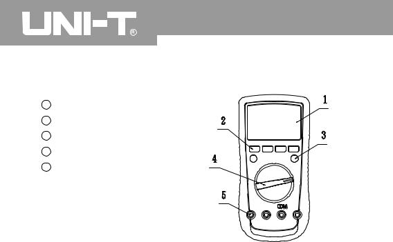
The Meter Structure (see figure 1)
1 LCD Display
2 Functional Buttons
3 Blue button
4 Rotary Switch
5 Input Terminal:
figure 1
10
Model UT61A/61B/61C/61D/61E: OPERATING MANUAL
Rotary Switch
Below table indicated for information about the rotary switch positions.
|
AC and DC Voltage Measurement |
mV |
|
|
AC Voltage Measurement (UT61D only) |
|
DC Voltage Measurement (UT61D only) |
|
Resistance Measurement |
|
Diode Test |
|
Continuity Test |
|
Capacitance Test |
|
Frequency and Duty Cycle Test |
|
Temperature in Celsius (UT61B and UT61C only) |
|
Temperature in Fahrenheit (UT61B and UT61C only) |
|
Transistor (UT61A only) |
|
DCA and ACA Measurement |
|
DCmA and ACmA Measurement |
|
10A DC and AC Measurement |
|
Sensor Test (UT61A only) |
OFF |
Power off |
|
11
Model UT61A/61B/61C/61D/61E: OPERATING MANUAL
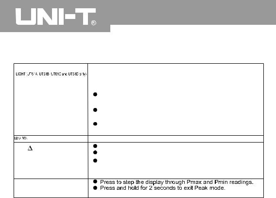
Functional Buttons
Below table indicated for information about the functional button operations.
Button |
Operation Performed |
|
Press and hold for 2 serconds to turn the display backlight on or off. |
Hold |
Press to enter or exit data hold mode. |
BLUE Button |
Press to select the alternate feature |
RANGE |
Press RANGE to enter the manual ranging mode; |
|
the Meter beeps. |
|
Press RANGE to step through the ranges available for the |
|
selected function; the Meter beeps. |
|
Press and hold RANGE for 2 seconds to return to autoranging; |
|
the Meter beeps |


 Press to select the maximum and minimum value.
REL |
Press to enter REL mode. |
|
Press again to exit REL mode |
||
|
||
|
For Model UT61C, UT61C and |
Press and hold for over 2 seconds to enter or exit RS232C or
USB mode.
PEAK (UT61E only)
 "CAL" means the meter enter self-calibration mode.
12
Model UT61A/61B/61C/61D/61E: OPERATING MANUAL
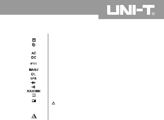
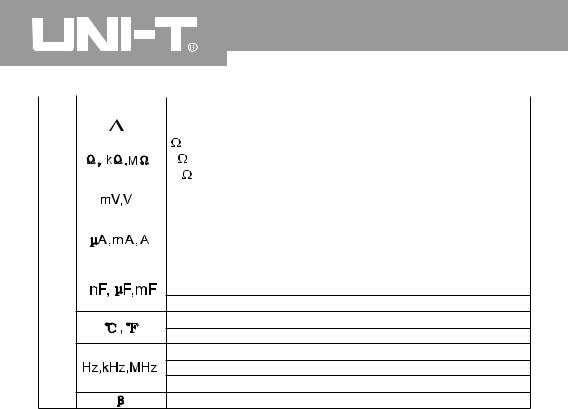
Display Symbols
No |
Symbol |
Meaning |
||||||
1 |
|
|
|
|
|
|
|
Data hold is active. |
2 |
|
|
|
|
|
|
|
Sleep Mode indicator |
3 |
|
|
|
|
|
|
|
Indicates negative reading. |
|
|
|
|
|
|
|
||
4 |
|
|
|
|
|
|
|
Indicator for AC measurement |
5 |
|
|
|
|
|
|
|
Indicator for DC measurement |
6 |
|
|
|
|
|
|
|
The Meter is in the auto range mode in which the Meter automatically |
|
|
|
|
|
|
|
|
selects the range with the best resolution. |
7 |
|
|
|
|
|
|
|
Indicator for manual ranging mode. |
8 |
|
|
|
|
|
|
|
The input value is too large for the selected range. |
9 |
|
|
|
|
|
|
|
Transistor testing indicator |
10 |
|
|
|
|
|
|
|
Test of diode |
11 |
|
|
|
|
|
|
|
The continuity buzzer is on. |
12 |
|
|
|
|
|
|
|
Maximum and Minimum reading. |
13 |
|
|
|
|
|
|
|
Data output is in progress |
14 |
|
|
|
|
|
|
|
The battery is low. |
|
|
|
|
|
|
|
|
Warning: To avoid false readings, which could lead to |
|
|
|
|
|
|
|
|
possible electric shock or personal injury, replace the battery |
|
|
|
|
|
|
|
|
as soon as the battery indicator appears. |
15 |
|
|
|
|
|
|
|
Sensor test is in progress |
|
|
|
|
|
|
|
|
|
13
|
|
|
Model UT61A/61B/61C/61D/61E: OPERATING MANUAL |
|
|
|
|
|
|
No |
Symbol |
Meaning |
|
|
16 |
|
The REL is on to display the stored value minus the present value. |
||
|
|
: Ohm. The unit of resistance. |
|
|
|
|
k |
: kilohm. 1 x 10³ or 1000 ohms. |
|
|
|
M |
: Megaohm. 1 x 10⁶ or 1,000,000 ohms. |
|
|
|
V: Volts. The unit of voltage. |
|
|
|
|
mV: Millivolt. 1 x 10⁻³ or 0.001 volts. |
|
|
|
|
A: Amperes (amps). The unit of current. |
|
|
|
|
mA: Milliamp. 1 x 10⁻³ or 0.001 amperes |
|
|
|
|
µA : Microamp. 1x 10⁻⁶ or 0.000001 amperes |
|
|
17 |
|
F: Farad. The unit of capacitance. |
|
|
|
|
µF : Microfarad. 1 x 10⁻⁶ or 0.000001 farads. |
|
|
nF : Nanofarad. 1 x 10⁻⁹ or 0.000000001 farads.
 : Centigrade. The unit of temperature.
 : Fahrenheit. The unit of temperature.
Hz: Hertz. The unit of frequency in cycles/second.
kHz: Kilohertz. 1 x 10³ or 1,000 hertz.
MHz: Megahertz. 1 x 10⁶ or1,000,000 hertz.
The unit of transistor
14
Model UT61A/61B/61C/61D/61E: OPERATING MANUAL
Measurement Operation
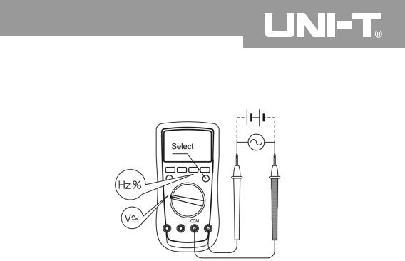
A. DC/AC Voltage Measurement (See figure 2)
figure 2
15

Model UT61A/61B/61C/61D/61E: OPERATING MANUAL
 Warning
To avoid harms to you or damages to the Meter from electric shock, please do not attempt to measure voltages higher than 1000V although readings may be obtained.
When measuring high voltage, take extra care to avoid electric shock.
1.Insert the red test lead into the V terminal and the black test lead into the COM terminal.
2.Set the rotary switch to V; DC measurement is default or press BLUE button to switch between DC and AC measurement mode.
3.Connect the test leads across with the object being measured. The measured value shows on the display.
UT61A, UT61B and UT61C: display effective value of sine wave (mean value response).
UT61D and UT61E: display true rms value.
4.Press Hz% to obtain the frequency and duty cycle value.
Input Amplitude: (DC electric level is zero)
Input Amplitude:  range
range 30%
30%
Frequency respouse:UT61A and B 400Hz
400Hz
UT61C,UT61D and UT61E 1KHz
1KHz
16

Model UT61A/61B/61C/61D/61E: OPERATING MANUAL
Note
•In each range, the Meter has an input impedance of 10M except mV range which input impedance is 3000M
 . This loading effect can cause measurement errors in high impedance circuits. If the circuit impedance is less than or equal to 10k
 , the error is negligible (0.1% or less).
•For UT61A and UT61B:When measuring mV, you must press RANGE manually to enter mV range.
•When voltage measurement has been completed, disconnect the connection between the testing leads and the circuit under test, and remove the testing leads
away from the input terminals of the Meter.
17
Model UT61A/61B/61C/61D/61E: OPERATING MANUAL
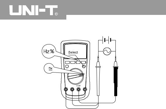
B. DC/AC Current Measurement (See figure 3)
A
figure 3
18

Model UT61A/61B/61C/61D/61E: OPERATING MANUAL
 Warning
Before connecting the Meter to the return circuit to be tested, cut off the current of the return circuit.
If the fuse burns out during measurement, the Meter may be damaged or the operator himself may be hurt.
Use proper terminals, function, and range for the measurement.
When the testing leads are connected to the current terminals, do not parallel them across any circuit.
To measure current, do the following:
1.Insert the red test lead into the  mA or A input terminal and the black test lead into the COM terminal.
2.Set the rotary switch to  A, mA, or A.
3.The Meter defaults to DC current measurement mode. To toggle between DC and AC current measurement function, press BLUE button.
4.Connect the test lead in serial to the return circuit to be tested. The measured value shows on the display.
19

Model UT61A/61B/61C/61D/61E: OPERATING MANUAL
UT61A, UT61B and UT61C: display effective value of sine wave (mean value response).
UT61D and UT61E: display true rms value.
5. Press Hz% to obtain the frequency and duty cycle value.
Input Amplitude: (DC electric level is zero)
Input Amplitude: range
range  30%
30%
Frequency response:UT61A and B  400Hz
400Hz
UT61C , UT61D andUT61E  1KHz
1KHz
Note
•If the value of current to be measured is unknown, use the maximum measurement position, and reduce the range step by step until a satisfactory reading is obtained.
•For safety sake, each measurement time for >5A current should be less than 10 seconds and the interval time between 2 measurements should be greater than 15 minutes.
•When current measurement has been completed, disconnect the connection between the testing leads and the circuit under test, and remove the testing leads
away from the input terminals of the Meter.
20
Model UT61A/61B/61C/61D/61E: OPERATING MANUAL
C. Measuring Resistance (See figure 4)
figure 4
21
 Loading...