

Page 1
Overview
This Operating Manual covers information on safety and
cautions. Please read the relevant information carefully
and observe all the Warnings and Notes strictly.
Warning
To avoid electric shock or personal injury, read the
“Safety Information” carefully before using the
Meter.
Unpacking Inspection
Open the package case and take out the Meter. Check
the following items carefully for any missing or
damaged part:
In the event you find any missing or damaged item,
please contact your dealer immediately.
Item
1
2
3
Description
English Operating Manual
Test Leads
Holster
Qty
1 pc
1 pair
1 pc
Safety Information
This Meter complies with IEC61010 Overvoltage Cate
-gory(CAT.II1000V, CAT. III 600V), Double Insulation
and Pollution Degree 2 standards.
Use the Meter only as specified in this operating manual,
otherwise the protection provided by the Meter may be
impaired.
In this manual, a Warning identifies conditions and
actions that pose hazards to the user, or may damage
the Meter or the equipment under test.
A Note identifies the information that user should pay
attention to.
To avoid possible electric shock or personal
injury, and to avoid possible damage to the Meter or
to the equipment under test, adhere to the following
rules:
z Before using the Meter inspect the case. Do
not use the Meter if it is damaged or the case
(or part of the case) is removed. Look for cracks
or missing plastic. Pay attention to the insulation
around the connectors.
z Inspect the test leads for damaged insulation
or exposed metal. Check the test leads for
continuity. Replace damaged test leads with
identical model number or electrical specifications
before using the Meter.
z When using the test leads, keep your fingers
behind the finger guards.
z Do not apply more than the rated voltage, as
marked on the Meter, between the terminals or
between any terminal and grounding.
z When the Meter is working at an effective voltage
over 60V in DC or 30V in AC, special care should
be taken from there is danger of electric shock.
z Use the proper terminals, function, and range
for your measurements.
z The rotary switch should be placed in the right
position and no any changeover of range shall
be made during measurement to prevent damage
of the Meter.
z Disconnect circuit power and discharge all high
-voltage capacitors before testing current,
resistance, diodes, continuity or capacitance.
z Start charging as soon as the power indicator
appears. With a low battery, the Meter might
produce false readings that can lead to electric
shock and personal injury.
z When servicing the Meter, use only the replacement
parts with the same model or identical electrical
specifications.
z The internal circuit of the Meter shall not be
altered at will to avoid damage of the Meter and
any accident.
z Soft cloth and mild detergent should be used to
clean the surface of the Meter when servicing.
No abrasive and solvent should be used to
prevent the surface of the Meter from corrosion,
damage and accident.
z Turn off the Meter when it is not in use
z Do not use or store the Meter in an environment
of high temperature, humidity, explosive,
inflammable and strong magnetic field. The
performance of the Meter may deteriorate after
dampened.
z The Meter is suitable for indoor use.
International Electrical Symbols
AC (Alternating Current).
DC (Direct Current).
AC or DC.
Grounding.
Double Insulated.
Low Battery Indication.
Continuity Test.
Diode.
Fuse.
Warning. Refer to the Operating Manual.
Conforms to Standards of European Union.
Capacitance Test
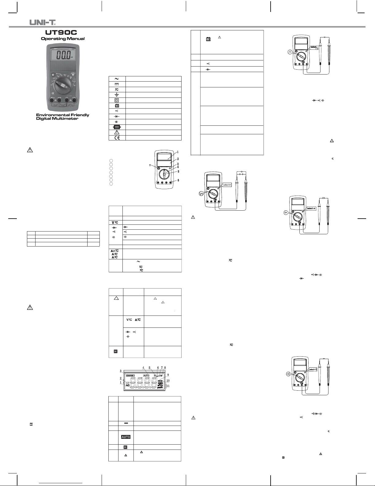
The Meter Structure (See Figure 1)
Fgure 1
1 LCD Display.
2 Solar Panel.
3 SELECT Button.
4 Rotary Switch.
5 HOLD Button.
6 Input Terminals
7 Relative Mode & RESET
Button
Rotary Switch
The table below offers information about the rotary
switch positions.
Rotary
Switch
Position
Function
AC/DC voltage measurement.
: Diode test.
: Resistance measurement.
Ω
AC or DC Current Measurement
Power is turned off.OFF
: Continuity test.
: Capacitance test.
Ω
Hz Frequency Test.
z 230V MAX:
Charge at 220VAC.
z 12-36V : Charge at
12-36V .
CHARGE
Functional Buttons
The table below offers information about the functional
button operations.
Button
Measuring
Function
Operation
Performed
RESET
Any rotary
switch position
except Hz and
CHARGE
Press RESET to enter
and exit the mode in any
measuring mode except in
frequency and charge
mode; the Meter beeps.
SELECT
Switches between AC and
DC voltage/current; the
Meter beeps. DC is default.
Switches between resistance,
diode, continuity and
capacitance measurements;
the Meter beeps. Resistance
is default.
Ω
Any rotary
switch
position
Press to enter and exit the
Hold mode in any mode,
the Meter beeps.
Display Symbols (See Figure 2)
Figure 2
No. Symbol Meaning
1
2
4
Indicates negative reading.
CHARGE
3
AC
Indicator for AC voltage or current.
The displayed value is the mean
value.
The battery is low.
Warning: To avoid false readings,
which could lead to possible electric
shock or personal injury, replace the
battery as soon as the battery
indicator appears.
Charge indicator.
The Meter is in the auto range
mode in which the Meter
automatically selects the range with
the best resolution.
Data hold is active.
5
The mode is on, under which
the stored value will be subtracted
from the displayed reading.
6
7
8
The voltage unit when charging is on.
V
Ω: Ohm. The unit of resistance.
kΩ: kilohm.1 x 10
3
or 1000 ohms.
MΩ: Megaohm. 1 x 10
6
or
1,000,000 ohms.
μA, mA, A
A: Amperes (amps). The unit of
current.
mA: Milliamp. 1 x 10
-3
or 0.001
amperes.
μA: Microamp. 1x 10
-6
or 0.000001
amperes.
V: Volts. The unit of voltage.
mV: Millivolt. 1 x 10
-3
or 0.001 volts.
Ω,kΩ,MΩ
mV, V
9
The continuity buzzer is on.
Test of diode.
10
11
μF, nF
F:
μF:
nF:
Farad. The unit of
capacitance.
Microfarad. 1 x 10⁻⁶or
0.000001 farads.
Nanofarad. 1 x 10⁻⁹ or
0.000000001 farads.
Hz:
kHz:
MHz:
Hertz.The unit of frequency
in cycles/second.
Kilohertz. 1 x 10³ or 1,000
hertz.
Megahertz.1 x 10
6
or
1,000,000 hertz.
Hz,
kHz,
MHz
Measurement Operation
A.
Measuring DC&AC Voltage (See Figure 3)
Figure 3
Warning
To avoid harm to you or damage to the Meter from
electric shock, please do not attempt to measure
voltages higher than 1000VDC / 750VAC RMS although
readings may be obtained.
Measuring AC Voltage
The AC voltage ranges are: 4.000V, 40.00V, 400.0V
and 750.0V. To measure AC Voltage, connect the Meter
as follows:
1. Insert the red test lead into the HzVΩ terminal and
the black test lead into the COM terminal.
2. Set the rotary switch to V and press SELECT
button to select AC measurement mode.
3. Connect the test leads across with the object being
measured.
The measured value shows on the display,which
is effective value of sine wave (mean value response).
red black
Note
z At 400mV range, the Meter has an input impedance
of 4000MΩ At all the other ranges the Meter has an
input impedance of 10MΩ This loading effect can
cause measurement errors in high impedance circuits.
If the circuit impedance is less than or equal to 10kΩ,
the error is negligible (0.1% or less).
z When AC voltage measurement has been completed,
disconnect the connection between the testing leads
and the circuit under test.
Measuring DC Voltage
The DC Voltage ranges are: 400.0mV, 4.000V, 40.00V,
400.0V and 1000V. To measure DC voltage, connect
the Meter as follows:
1. Insert the red test lead into the HzVΩ terminal and
the black test lead into the COM terminal.
2. Set the rotary switch to V ; DC measurement is
default or press SELECT button to select DC
measurement mode.
3. Connect the test leads across with the object being
measured.
The measured value shows on the display.
Note
z At 400mV range, the Meter has an input impedance
of 4000MΩ At all the other ranges,the Meter has
an input impedance of 10M Ω . This loading effect
can cause measurement errors in high impedance
circuits. If the circuit impedance is less than or equal
to 10k Ω , the error is negligible (0.1% or less).
z When DC voltage measurement has been completed,
disconnect the connection between the testing leads
and the circuit under test.
B.Measuring Resistance, Diodes, Continuity &
Capacitance
Figure 4
Warning
To avoid harms to you, never attempt to input over
60V in DC or 30V rms in AC.
To avoid damages to the Meter or to the devices
under test, disconnect circuit power and discharge
all the high-voltage capacitors before measuring
resistance, diodes, continuity & capacitance
For testing capacitance, use the DC Voltage function
to confirm that the capacitor is discharged.
Measuring Resistance
(See Figure 4)
The resistance ranges are: 400.0Ω, 4.000kΩ, 40.00kΩ,
400.0kΩ , 4.000MΩ
and 40.00MΩ. To measure resistance,
connect the Meter as follows:
red black
1. Insert the red test lead into the HzVΩ terminal and
the black test lead into the COM terminal.
2. Set the rotary switch toΩ
,
resistance
measurement (Ω) is default or press SELECT button
to select Ω measurement mode.
3. Connect the test leads across with the object being
measured.
The measured value shows on the display.
Note
z The test leads can add 0.1Ωto 0.2Ωof error to
resistance measurement. To obtain precision readings
in low-resistance measurement, that is the range of
400.0Ω, short-circuit the input terminals beforehand,
using the relative value function button RESET to
automatically subtract tthe shorted value from the
reading.
z
For high-resistance measurement (>1MΩ), it normally
takes
several seconds to obtain a stable reading.
z IfΩ reading with shorted test leads is not 0.5Ω,
check for loose test leads, incorrect function selection,
or enabled Data Hold function.
z The LCD displays OL indicating open-circuit for the
tested resistor or the resistor value is higher than the
maximum range of the Meter.
z When resistance measurement has been completed,
disconnect the connection between the testing leads
and the circuit under test.
Testing Diodes (See Figure 5)
Figure 5
Use the diode test to check diodes, transistors, and other
semiconductor devices. The diode test sends a current
through the semiconductor junction, and then measures
the voltage drop across the junction. A good silicon junction
drops between 0.5V and 0.8V.
To test a diode out of a circuit, connect the Meter as
follows:
1. Insert the red test lead into the HzVΩ terminal and
the black test lead into the COM terminal.
2. Set the rotary switch toΩ and press SELECT
button to select measurement mode.
3.
For forward voltage drop readings on any semiconductor
component, place the red test lead on the component’s
anode and place the black test lead on the component’s
cathode.
The measured value shows on the display.
Note
z In a circuit, a good diode should still produce a forward
voltage drop reading of 0.5V to 0.8V; however, the
reverse voltage drop reading can vary depending
on the resistance of other pathways between the
probe tips.
red black
Figure 6
z Connect the test leads to the proper terminals as
said above to avoid error display. The LCD will
display OL indicating open-circuit for wrong connection.
The unit of diode is Volt (V), displaying the positive-
connection voltage-drop value.
z When diode testing has been completed, disconnect
the connection between the testing leads and the
circuit under test.
Testing for Continuity
(See Figure 6)
To test for continuity, connect the Meter as below:
1. Insert the red test lead into the HzVΩ terminal and
the black test lead into the COM terminal.
2. Set the rotary switch toΩ and press
SELECT
button to select measurement mode.
3. The buzzer does not sound if the circuit is disconnected
with resistance value is > 100Ω
The buzzer sounds continuously if the circuit is in
good condition with resistance value 10Ω.
4. The nearest circuit resistance value shows on the
display, the unit isΩ.
Note
z The LCD displays OL indicating the resistance of
the circuit being tested is higher than 400Ω.
z The buzzer sounds once if the RESET, SELECT
or is pressed on.
red black
UT90C is a new generation of environment friendly
instrument, which can be powered by 220VAC, 12-36V
(DC or AC) or solar energy without need of battery and
therefore doesn’t pose chemical impact to the environ
-ment. The packing is toxic-free , recyclable and totally
safe to the environment.
The Multimeter is 4000-count auto-ranging digital multi
-meter(hereafter referred to as “the Meter”) and can
measure DC&AC voltage, DC&AC current, resistance,
capacitance, frequency, diode and continuity. It also
offers large LCD display, full icon display, overload pro
-tection, data hold, Relative mode features.
Page 2
P/N :110401104421X
** END **
This operating manual is subject to change without notice.
Figure 7
z When continuity testing has been completed,
disconnect the connection between the testing leads
and the circuit under test.
Measuring Capacitance
(See Figure 7)
The capacitance ranges are: 40.00nF, 400.0nF,4.000μF,
40.00μF, and 100.0μF. To measure capacitance,connect
the Meter as follows:
red black
1. Insert the red test lead into the HzVΩ terminal and
the black test lead into the COM terminal.
2. Set the rotary switch toΩ and press SELECT
button to select measurement mode. The existing
of the Meter built-in equalized capacitance will affect
the accuracy. To increase the accuracy of capacitance
measurement, press button before measuring to
reset the display to 0.
3. Connect the test leads across with the object being
measured.
The measured value shows on the display.
Note
z The LCD displays OL indicating the capacitor is short
-circuited or the capacitor value being tested is overload.
Figure 8
z For testing the capacitor with polarity, connect the
red test lead to anode & black test lead to cathode.
z It takes a longer time when testing a capacitor value
which is higher than 10μF range.
z When capacitance measurement has been completed,
disconnect the connection between the testing leads
and the circuit under test.
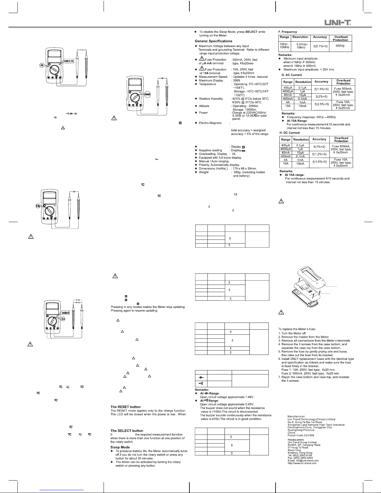
C.Measuring Frequency
(See Figure 8)
Warning
To avoid harm to you, please do not attempt to
input frequency voltage being tested higher than 30V.
red black
The measurement ranges are from 10Hz to 10MHz.
To measure frequency, connect the Meter as follows:
1. Insert the red test lead into the HzVΩ terminal and
the black test lead into the COM terminal.
2. Set the rotary switch to Hz.
3. Connect the test leads across with the object being
measured.
The measured value shows on the display.
Figure 8
black red
Note
z When Hz measurement has been completed,
disconnect the connection between the testing leads
and the circuit under test.
D.Measuring DC&AC Current
(See Figure 9)
Warning
Never attempt an in-circuit current measurement
where the open-circuit voltage between the circuit
and ground is greater than 250V.
If the fuse burns out during measurement, the Meter
may be damaged or the operator himself may be hurt.
Use proper terminals, function, and range for the
measurement. When the testing leads are connected
to the current terminals, do not parallel them across
any circuit.
The current measurement has 3 measurement positions
on the rotary switch: μA , A and mA
.
TheμA has a 400.0μA and 4000μA range, with auto
ranging; the mA has a 40.00mA and 400.0mA range,
with auto ranging; A position has a 4.000A and 10.00A
range, with auto ranging.
To measure current, do the following:
1. Turn off power to the circuit. Discharge all high voltage capacitors.
2. Insert the red test lead into the μAmA or 10A terminal
and the black test lead into the COM terminal.
Use the 10A terminal and A range if the current
value to be tested is unknown.
3. Set the rotary switch to μA , mA orA .
4. The Meter defaults to DC current measurement mode.
To toggle between DC andAC current measurement
function, press SELECT button. AC current is
displayed as an mean value (calibrated against RMS
value of sine wave
5. Break the current path to be tested. Connect the red
test lead to the more positive side of the break and
the black test lead to the more negative side of the
break.
6. Turn on power to the circuit.
The measured value shows on the display.
Note
z For safety sake, the measuring time for high current
should be less than 10 seconds for each measurement
and the interval time between 2 measurements
should be greater than 15 minutes.
z When current measurement has been completed,
disconnect the connection between the testing leads
and the circuit under test, and remove the testing
leads away from the input terminals of the Meter.
Figure 10
E.Power Charging (See Figure 10)
red black
Warning
Start charging as soon as the power indicator
appears. With a low battery, the Meter might produce
false readings that can lead to electric shock and
personal injury.
To avoid damage to the Meter, please do not attempt
to turn the rotary switch during charging.
To set up charging as follows:
z Charge at 220V AC
1. Insert the red test lead into the HzVW terminal and
the black test lead into the COM terminal.
2. Set the rotary switch to 230V MAX.
3. Connect the test leads to two ends of 220VAC
power supply.
4. CHARGE shows on the display.
5. The charging time is around 15minutes. Then the
Meter can work continuously for more than 90 minu
-tes(eg: under DCV ranges)
z Charge by Solar Power
Charging through the solar panel from sunshine.
Remarks:
z When 0.7V displays on the display, it means the rated
charging voltage.
z The LCD will be closed when the power is low.
When the LCD is turned on for the first time during
charging or after 5-minute charging, please press
RESET in order to make the meter display the current
correct charging value.
z When power charging has been completed, disconnect
the connection between the testing leads and the
supply power.
z Charge at 12-36V
1. Insert the red test lead into the HzVΩ erminal and
the black test lead into the COM terminal.
2. Set the rotary switch to 12-36V .
3. Connect the test leads to two ends of 12-36V power
supply.
4. CHARGE shows on the display.
5. The charging time is around 30 minutes. Then the
Meter can work continuously for more than 90 minu
-tes(eg: under DCV ranges)
Operation of Hold Mode
Warning
To avoid possibility of electric shock, do not use Hold
mode to determine if circuits are without power. The
Hold mode will not capture unstable or noisy readings.
The Use of Relative Value Mode
The mode applies to all measurement functions except
frequency and charge function,it subtracts a stored
value from the present value and displays the relative
value ( ) as the result
The Hold mode is applicable to all measurement functions.
z Press to enter Hold mode; the Meter beeps.
z Press again to exit Hold mode; the Meter beeps.
z In Hold mode, is displayed.
The definition is as follows:
z Relative value ( ) = present value – stored value
For instance, if the stored value is 20.0V and the
present measurement value is 22.0V, the reading
would be 2.0V. If a new measurement value is equal
to the stored value then display 0.0V.
To enter or exit mode:
z Use rotary switch to select the measurement function
before selecting RESET. If measurement functions
change manually after RESET is selected, the Meter
exits the mode.
z Press RESET to enter mode, and the present
measurement range is locked and display the last
measurement value as “0” as the stored value.
z Press RESET again to reset the stored value and
exit Mode.
z Turn the rotary switch back and forth one time to return
to auto ranging mode. This only applies to those
functions having auto ranging.
z Safety/Compliances : IEC61010: CAT. II 1000V,
CAT. III 600V overvoltage
and double insulation
standard.
z Certification :
Accuracy: (a% reading + b digits),guarantee for 1 year.
Operating temperature:23oC
5oC.
Relative humidity:<75%.
Temperature coefficient: 0.1 x(specified accuracy) / 1
o
C.
Remarks:
z Input impedance: approx. 10MΩ.
z Frequency response: 40Hz ~ 400Hz.
z Displays RMS value of sine wave (mean value
response).
B. DC Voltage
Remark:
z Input impedance:
At 400mV range: above 4000MΩ.
All other ranges: approx. 10MΩ.
A.AC Voltage
4V
40V
400V
750V
1mV
10mV
100mV
1V
Range Resolution
(1%+5)
Overload
Protection
Accuracy
(1.2%+5)
1000V DC
or 750V AC
continuous.
Accuracy Specification
400mV
4V
40V
400V
1000V
0.1mV
1 mV
10 mV
100mV
1V
Range Resolution
Overload
Protection
Accuracy
(0.8%+3)
1000V DC
or 750V AC
continuous.
(1%+3)
(0.8%+1)
C. Resistance
Range Resolution
Overload
Protection
Accuracy
400Ω
4kΩ
40kΩ
400kΩ
4MΩ
40MΩ
0.1Ω
1Ω
10Ω
100Ω
1kΩ
10kΩ
(1%+2)
600Vp
(1.2%+2)
(1.5%+2)
(1.2%+2)
Remarks:
z Open circuit voltage: approx. 0.45V
D. Diode & Continuity
1mV
1Ω
Range Resolution Overload Protection
600Vp
E. Capacitance
Range Resolution
Overload
Protection
Accuracy
40nF
400nF
4μF
40μF
100μF
10pF
100pF
1nF
10nF
100nF
(3%+5)
600Vp
(3%+10)
(4%+5)
Maintenance
This section provides basic maintenance information
including fuse replacement instruction.
Warning
Do not attempt to repair or service your Meter unless
you are qualified to do so and have the relevant
calibration, performance test, and service information.
To avoid electrical shock or damage to the Meter,
do not get water inside the case.
A. General Service
z Periodically wipe the case with a damp cloth and
mild detergent. Do not use abrasives or solvents.
z To clean the terminals with cotton bar with detergent,
as dirt or moisture in the terminals can affect readings.
z Turn the Meter off when it is not in use and take out
the battery when not using for a long time.
z Do not store the Meter in a place of humidity, high
temperature, explosive, inflammable and strong
magnetic field.
B.Replacing the Fuses
(See Figure 11)
Screw
Holster
Figure 11
Warning
To avoid electrical shock or arc blast, or personal
injury or damage to the Meter, use specified fuses
ONLY in accordance with the following procedure.
Replacement of the fuses is seldom required. Burning
of a fuse always results from improper operation.
’
’
the LCD is turned on for the first time during charging or
after 5-minute charging, please press RESET in order to
make the meter display the current correct charging value.
is used to select
Performance over 1V/m is
not specified.
Low Battery Indicator
When under RF field of
1V/m,
 Loading...