

Page 1

L
DIGITAL MULTIMETER
True RMS
6000 Counts
FUSED
CAT II 600V
FUSED
MAX 30 sec EACH 15min
1000V
750V
max
Benchtop Digital Multimeter
User Manual
Page 2
1
I. Introduction
UT8803 is a professional 6000 count benchtop multimeter with high accuracy and outstanding performance.
It supports multiple measurements:
AC/DC voltage
AC/DC current
Resistance
Frequency
Capacitance
Inductance
Audion (hFE)
Diode(LED)
Thyristor(SCR)
Continuity
Please carefully read and comply with all warnings and cautions in this manual.
II. Open box inspection
Open the package box and take out the instrument. Please check whether the following items are deficient
or damaged and contact your supplier immediately if they are.
User Manual(DVD-R)----------------------1pc
Test leads-------------------------------------1pair
Alligator clip test line-----------------------1pair
Power line------------------------------------1pc
Software DVD-------------------------------1pc
USB cable------------------------------------1pcs
Warranty--------------------------------------1pc
Warning: When the measured voltage is greater than 600V, The instrument cannot be used for
measurements in CAT II, CAT III and CAT IV environment
Page 3

2
III. Safety instructions
Safety standards
This instrument strictly follows the EN 61010-1: 2010, EN 61326: 2013, RoHS, pollution grade II safety
standard, CAT II 600V.
Unplug the power cord when the instrument is not in use.
Note: In the case that the instrument is not used in accordance with the operation instructions,
the protection provided by the instrument may be weakened or lost.
CLEANING
Be sure meter is turned off and wipe with a clean ,dry lint-free cloth.
Do not use abrasive cleaners or solvents
Power cord
specification:
1) Before using the instrument, please check if there is any item which is damaged or behaving abnormally.
If any abnormal item is found (such as: test lead bared, housing case damaged, LCD broken, etc.),
please stop using the instrument. It is strictly prohibited to use an instrument without shell cover.
Otherwise, there is a danger of electric shock.
2) If test lead is damaged, replace with the same type or of the same specifications.
3) Do not touch bare wire, connectors, input terminal or circuit being measured.
4) Use caution to measure voltage >DC 60V or AC 36Vrms, keep fingers behind finger guard to prevent
shock hazard.
Before each use, verify operation by testing a known working circuit that is within the rating of this unit.
5) When measuring unknown voltage, switch the dial to the maximum range position.
6) Do not impose voltage or current exceeding the specified ones on the instrument.
7) Functional dial should be switched to proper position. After each measure, disconnect the test leads
with the circuit. Pull out the power line if not use for long time. Do not switch the functional dial during
measurement.
Approval NO.
116006
40036455
40040244
Rating
300/500V
16A 250~
10A 250~
Description
H05VVF 3X0.75mm²
XR-T002
XR-W002
Name
CORD
PLUG
CONNECTOR
Page 4

3
IV. General specifications
1) Max voltage between input terminal and COM jack: 1000V DC/750V AC
2) Fuse Type:
10A Jack: (CE) F1 (12A H 1000V) Fuse (Φ6.3x32) mm
mA/μA Jack: (CE) 600mA H 1000V Fuse (Φ6.3x32) mm
3) Display: Max value: 5999; refresh 2~3 times/s
4) Range: Auto
5) Polarity: Auto
6) Overrange indicator: OL
7) Operating temperature: 0~40˚C (32˚F~104 ˚F)
8) Storage temperature: -10 ˚~50 ˚C (14 ˚F~122 ˚F)
9) Relative humidity: ≤75% at 0 ˚C~30 ˚C; ≤50% at 30 ˚C~40 ˚C
10)Electromagnetic compatibility:
RF=1V/m, overall accuracy=specified accuracy+5% of range.
RF>1V/m, no specified calculation.
11)Power Supply: AC 100V/120V/127V/220V/230VAC/240V, 450-440Hz, 28VA max Protection fuse being
used: For AC 100V/120V/127V,AC 250V T 250mA For AC 220V/230V/240V, AC 250V T 125mA μA mA
FUSE: 400mA/1000V
12)Dimension: 320mm*265mm*110mm
13)Weight: 3100g (accessories excluded)
14.Safety standards: IEC 61010: CAT II 600V
15.CAT II: It is applicable to test and measuring circuits connected directly to utilization points (socket
outlets and similar points) of the low-voltage MAINS installation.
16)Temperature coefficient: 0.1*(specified accuracy)/ ˚C (<18 ˚C or ≥28 ˚C)
8) Do not use or store the instrument in high temperature, high humidity, flammable, explosive or strong
magnetic field environments.
9) Do not change the internal circuit of the instrument in order to avoid the damage to the instrument and
users.
10)Switch off the power supply after measurement
Page 5
4
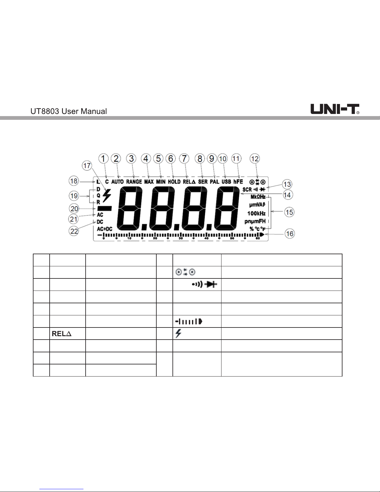
V.Display screen
1
2
3
4
5
6
7
8
9
10
11
12
13
14
15
16
17
18
19
HOLD
MAX
MIN
USB
PAL
SER
SCR
RANGE
AUTO
C
hFE
L
D Q R
Capacitance
Auto range
Manual range
Maximum value
Minimum value
Data hold
Relative value
Series
Parallel
USB connection
Diode& thyristor polarity
Thyristor/continuity/
Audion magnification
Reading
Unit
Stimulation bargraph
High voltage
Inductance
Capacitance loss factor, inductance
quality factor, equivalent resistance
measurement.
Page 6
5
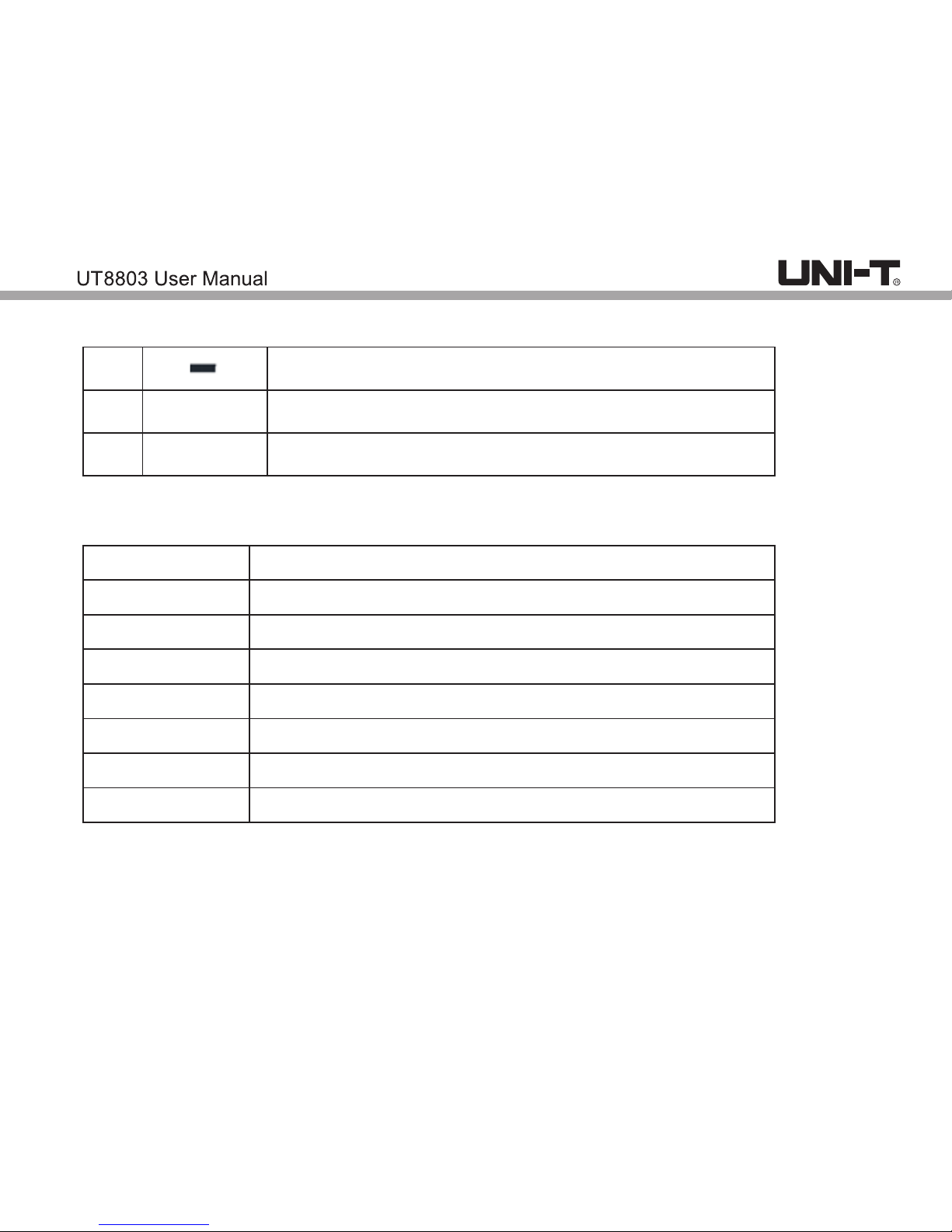
15.Measurement units:
mV、V
μA、mA、A
Ω、kΩ、MΩ
nF、 F、mF μ
μH、mH、H
Hz、kHz、MHz
β
℃
/
℉
20.
21.
AC
22.
DC
Negative value
Alternative current
Direct current
Voltage
Current
Resistance
Capacitance
Inductance
Frequency
Thyristor magnification
Temperature
Page 7
6
VI. Functions
V COM←→
V ←→ COM
V ←→ COM
V ←→ COM
V ←→ COM
V ←→ COM
V ←→ COM
V ←→ COM
V ←→ COM
V ←→ COM
μA mA ←→ COM
A ←→ COM
μA mA ←→ COM
A ←→ COM
℃
/
℉
SCR
hFE
A
µA mA
A
µA mA
R
Q
D
L
C
Hz %
Ω
V
V
Functions (measurement modes)
DC voltage
AC voltage
Resistance
Continuity
Frequency/ duty ratio
Capacitance
Inductance
Capacitance loss factor
Inductance quality factor
Equivalent resistance
DC current
DC current
AC current
AC current
Diode(LED)
Audion magnification
Thyristor measurement
Temperature
Multifunction socket (UTS-03A)
Multifunction socket (UTS-03A)
Multifunction socket (UTS-03A)
V-COM
Multifunction socket (UTS-03A)
Position
Input terminal
Page 8
7
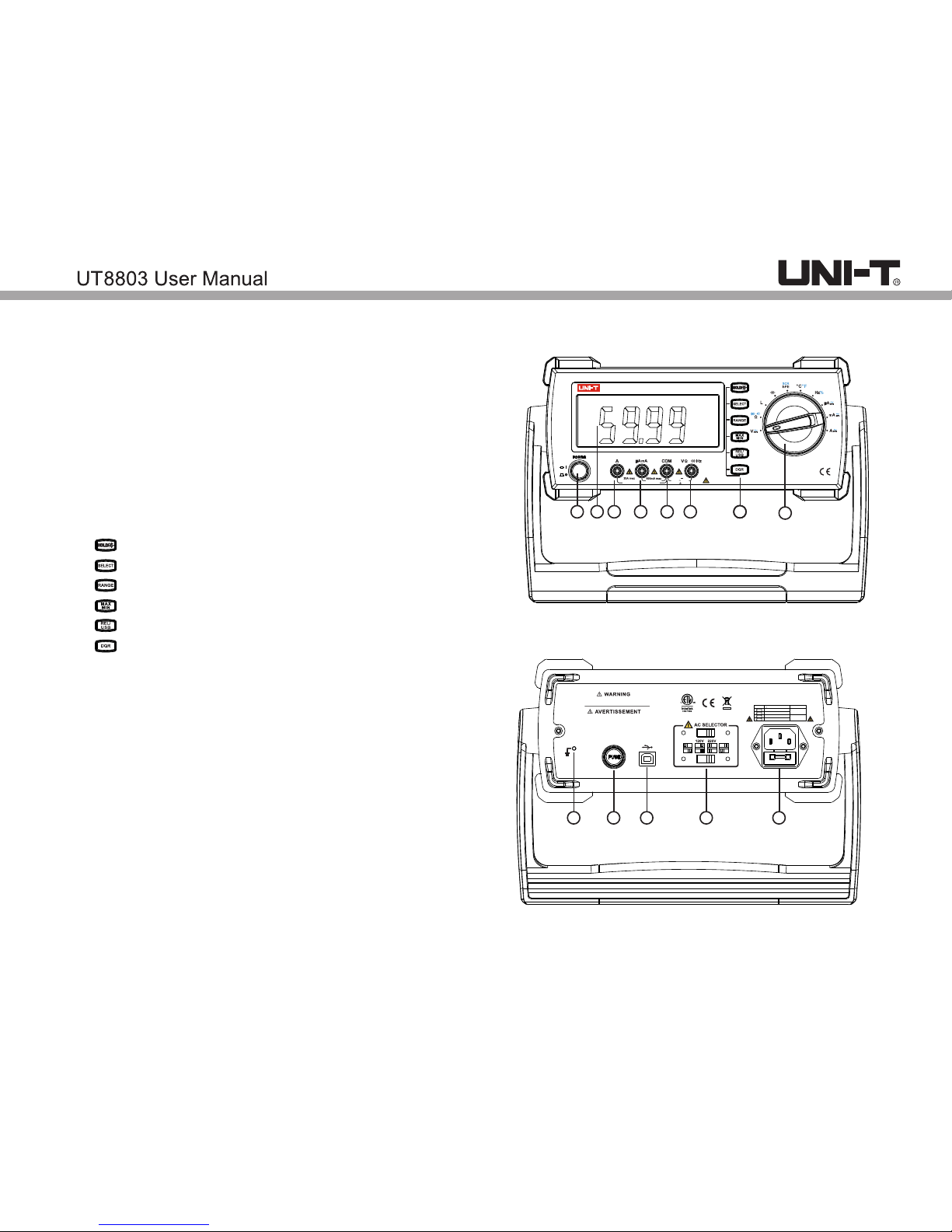
VII. Structure
1. Power switch
2. Display screen
3. 20A jack
4. μA/mA jack
5. COM jack
6. Function jack(voltage, resistance, inductance,
capacitance, frequency, continuity, diode, duty ratio)
7. Buttons:
L
DIGITAL MULTIMETER
True RMS
6000 Counts
FUSED
CAT II 600V
FUSED
MAX 30 sec EACH 15min
1000V
750V
max
1
2 3 4 5 6 77
8
F2 F600mA 1000V
100V
240V
TO AVOID ELECTRIC SHOCK, REMOVE THE TEST
LEADS AND TURN OFF THE POWER INPUT BEFORE
OPENING THE CASE AND REPLACING THE FUSE.
POUR ÉVITER UN CHOC ÉLECTRIQUE, RETIREZ
LES CORDONS DE MESURE ET ÉTEIGNEZ
L'ALIMENTATION AVANT D'OUVRIR LA CASE
ET DE REMPLACER LE FUSIBLE.
SELECTOR LINE(45-440Hz,28VA Max) FUSE
100V
120V
AC 100V
AC 120/127V
220V
240V
AC 220/230V
AC 240V
AC 250V T250mA
AC 250V T125mA
9
10 11 12 13
Data hold/backlight
Function switch
Range switch
Max/min value
Relative value/USB connection
Loss factor/ quality factor/ equivalent resistance
8.Function dial
9.Grounding
10.Fuse dial (F2 600mA)
11.USB port
12.AC voltage switch
13.Socket
Page 9

8
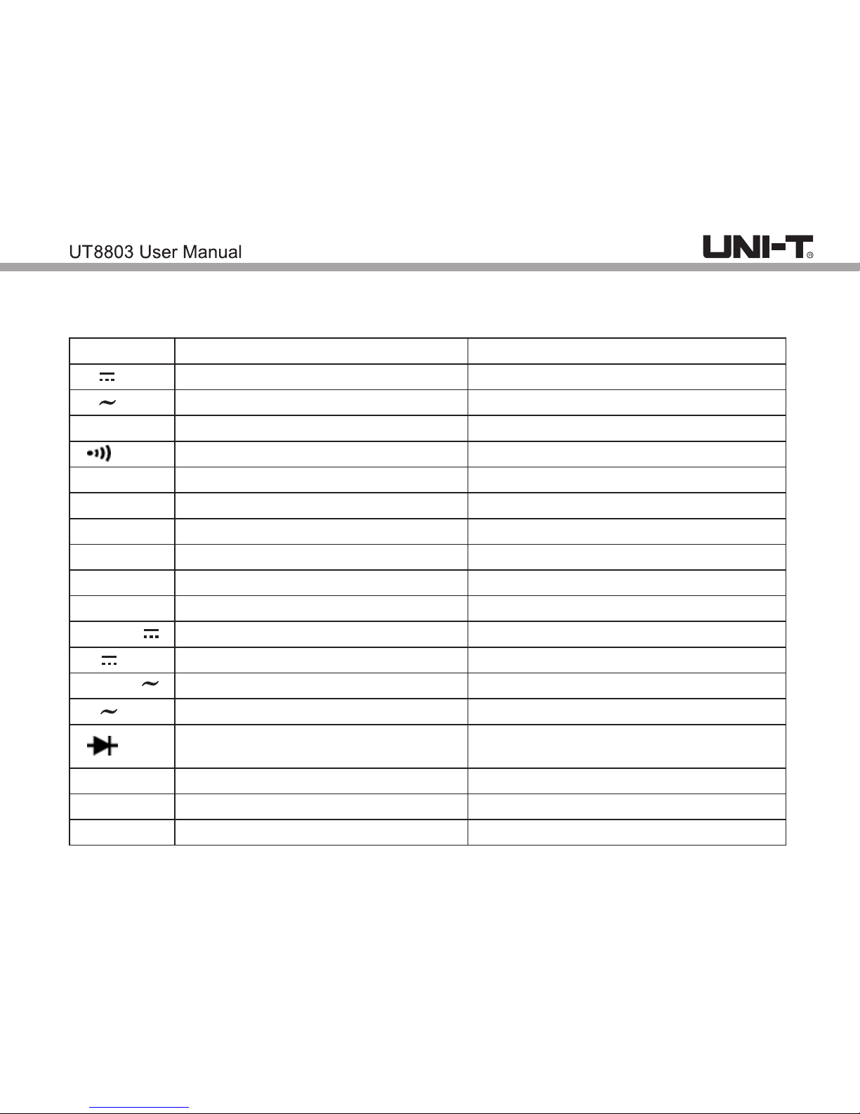
Symbols on meter
Power on
Power off
Direct current
Alternating current
Ground Terminal
Caution, possibility of electric shock
Warning or caution, To ensure safe operation and service of this meter,
follow all warnings and instructions detailed in this manual.
USB port
Do not place equipment and its accessories in the trash. Items must be
properly disposed of in accordance with local regulations.
Comply with European Union Directive
Conforms to UL STD. 61010-1, 61010-030, Certified to CSA STD.
C22.2 No. 61010-1, 61010-030.
It is applicable to test and measuring circuits connected directly to utilization
points (socket outlets and similar points) of the low-voltage MAINS installation.
CAT II
Page 10

9
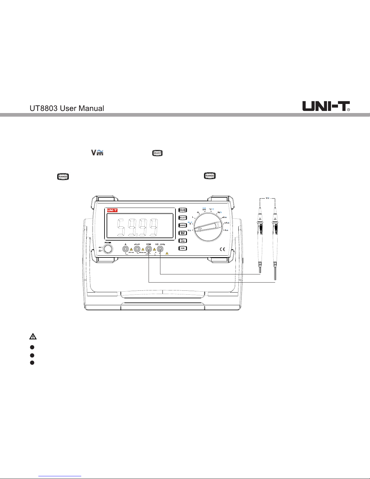
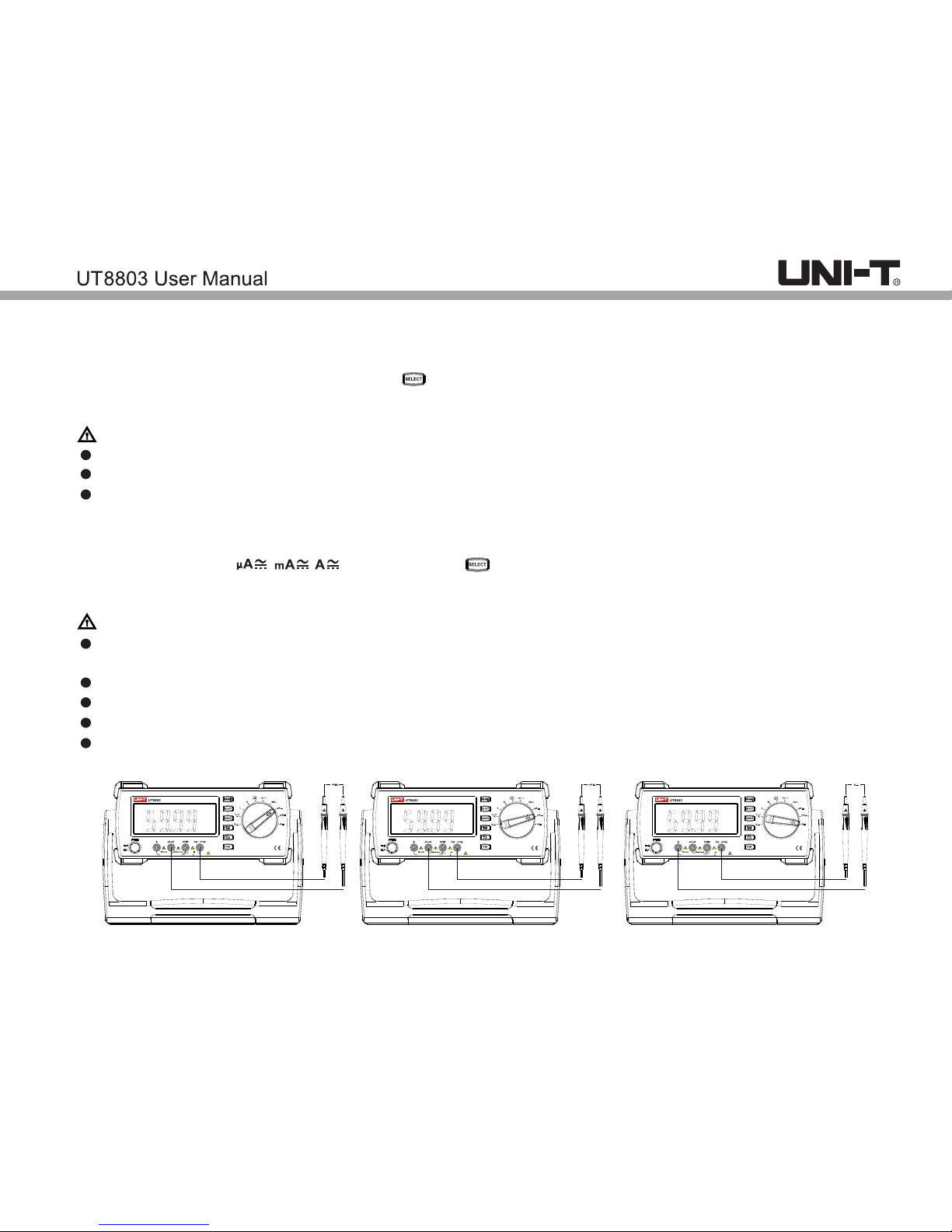
VIII. Operation instructions
Note: Select the corresponding input terminal. Functional dial should be switched to proper position
1. DC voltage measurement
a) Insert red test lead to V jack, black lead to COM jack.
b) Switch the dial to position, press button to enter DC measurement mode (figure 1). Connect
the test leads to the load in parallel.
c) Reading displayed.
d) Press button to manually switch the range. Press 4 times to enter mV range.
Note:
Do not input voltage over 1000V, or it may pose shock hazard.
Use caution to measure high voltage
After each measurement, disconnect test leads and circuit being measured.
黑
红
L
DIGITAL MULTIMETER
True RMS
6000 Counts
FUSED
CAT II 600V
FUSED
MAX 30 sec EACH 15min
1000V
750V
max
Page 11
10
2.AC voltage measurement
a) Insert red test lead to V jack, black lead to COM jack.
b) Switch the dial to position, press button to enter AC measurement mode (figure 1). Connect
the test leads to the load in parallel.
c) Reading displayed. (Sine wave true RMS)
d) Press button to manually switch the range. Press 4 times to enter mV range.
Note:
Do not input voltage over 750V, or it may pose shock hazard.
Use caution to measure high voltage
After each measurement, disconnect test leads and circuit being measured.
黑
红
L
DIGITAL MULTIMETER
True RMS
6000 Counts
FUSED
CAT II 600V
FUSED
MAX 30 sec EACH 15min
1000V
750V
max
Page 12

11
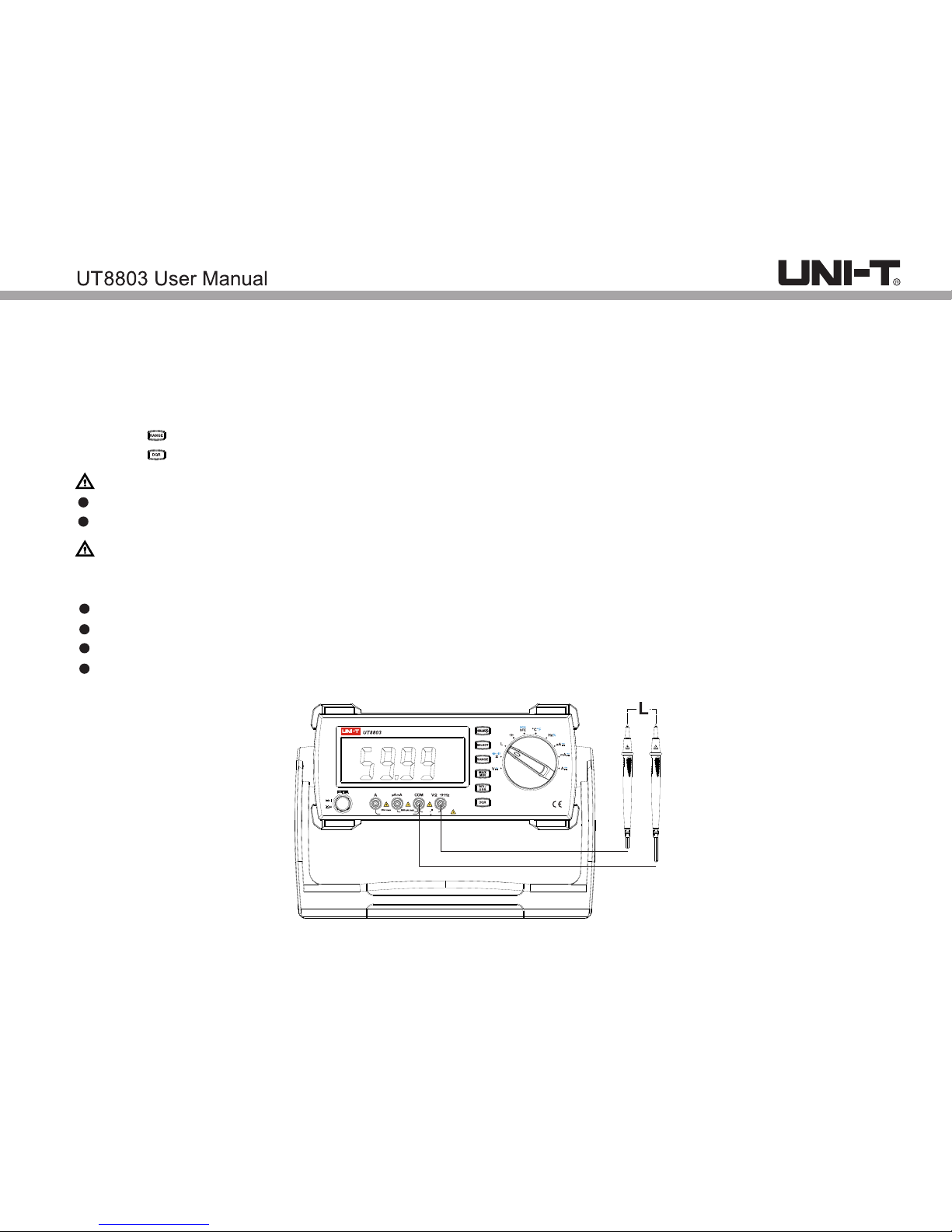
3.Resistance measurement
a) Insert red test lead to Ω jack, black lead to COM jack.
b) Switch the dial to position, press button to enter resistance measurement mode (figure 2).
Connect the test leads to the load in parallel.
c) Reading displayed.
d) Press button to manually switch the range.
Note:
If the resistor is open or over the range, the “OL” symbol will be displayed on the screen.
Before measuring resistance, switch off the power supply of the circuit, and fully discharge all capacitors.
When measuring low resistance, the test leads will produce 0.1Ω~0.2Ω measurement error. To obtain
accurate measurement, short the test leads and use REL function.
If the resistance when shorted is more than 0.5Ω, please check if test leads are loosened or damaged.
When measuring high resistance above 1MΩ, it is normal to take a few seconds to steady the readings.
For steady readings, short test line can be used for measure.
Do not input voltage over 30V (sine wave RMS), (peak value 42V) or DC 60V.
After each measurement, disconnect test leads and circuit being measured.
黑
红
L
DIGITAL MULTIMETER
True RMS
6000 Counts
FUSED
CAT II 600V
FUSED
MAX 30 sec EACH 15min
1000V
750V
max
Page 13

12
4.Diode measurement
Method 1:
a) Insert red test lead to jack, black lead to COM jack.
b) Switch the dial to position, press button to enter diode measurement mode (figure 2). Connect
the test leads to the load in parallel.
When appears, positive pole: red test lead; negative pole: black test lead
When appears, pole: black test lead; negative pole: red test lead
c) Display reading of positive onset voltage of PN junction.
Method 2:
a) Insert UT-S03A (multi-function socket)to the corresponding socket.(figure3)
b) Insert the diode or LED pin to the socket marked with DIODE
When appears, positive pole: right side of socket; negative pole: left side of socket
When appears, positive pole: left side of socket; negative pole: right side of socket
c) Display reading of positive onset voltage of PN junction.
黑
红
L
DIGITAL MULTIMETER
True RMS
6000 Counts
FUSED
CAT II 600V
FUSED
MAX 30 sec EACH 15min
1000V
750V
max
Page 14

13
5.Continuity measurement
a) Insert red test lead to Ω jack, black to COM jack.
b) Switch the dial to position, press to enter continuity measurement. Connect the test leads to the
resistor in parallel. If circuit is well conducting, resistance<10Ω, buzzer goes off continuously; if circuit
is open, resistance>50Ω, buzzer does not go off.
c) Reading is displayed.
Note:
Before measurement, please switch off all power supply and fully discharge all capacitors.
Do not input voltage over 30V (sine wave RMS), (peak value 42V) or DC 60V.
Disconnect test leads with the circuit after measurement.
黑
红
L
DIGITAL MULTIMETER
True RMS
6000 Counts
FUSED
CAT II 600V
FUSED
MAX 30 sec EACH 15min
1000V
750V
max
Page 15
14
6.Inductance measurement
a) Insert red test lead to L jack, black test lead to COM jack.
b) Switch the dial to L position, connect test leads with the inductance in parallel.
c) Reading is displayed.
d) Press to manually switch the range.
e) Press to switch Q/R functions, long press this button to return to inductance measurement.
Note:
Before measurement, please switch off all power supply and fully discharge all capacitors.
For accuracy, please reset the reading to 0 before measurement.
Method:
1. When the test leads in open status and frequency is 1kHz, press REL to reset the reading to zero.
2. When the test leads are shorted and frequency is 10kHz, press REL to reset the reading to zero.
For inductance over 1H, it takes long time to steady the reading
Values of capacitance loss factor (D) and inductance quality factor (Q) are only for reference.
Do not input voltage over 30V (sine wave RMS), (peak value 42V) or DC 60V.
Disconnect test leads with the circuit after measurement.
黑
红
L
DIGITAL MULTIMETER
True RMS
6000 Counts
FUSED
CAT II 600V
FUSED
MAX 30 sec EACH 15min
1000V
750V
max
Page 16
15
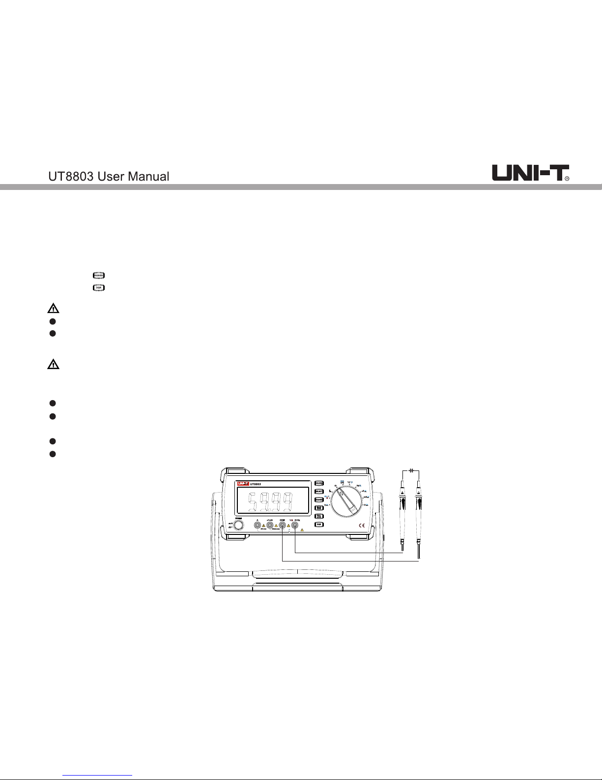
7.Capacitance measurement
a) Insert red test lead to C jack, black test lead to COM jack.
b) Switch the dial to ** position, connect test leads with capacitor in parallel.
c) Reading is displayed,
d) Press to manually switch the range.
e) Press to switch Q/R functions, long press this button to return to capacitance measurement.
Note:
If the circuit being measurement is shorted or the capacitance is over range, OL will appear.
There may be dozens of remaining digits because of the intrinsic capacitors. Please reset the reading
to 0 before measurement.
Method:
1. When the test leads in open status and frequency is 1kHz, press REL to reset the reading to zero.
2. When the test leads are shorted and frequency is 100Hz, press REL to reset the reading to zero.
For capacitor over 600μF, it takes long time to obtain reading.
Before measurement, please switch off all power supply and fully discharge all capacitors.
Pay particular attention to capacitors with high voltage.
Do not input voltage over 30V (sine wave RMS), (peak value 42V) or DC 60V.
Disconnect test leads with the circuit after measurement.
黑黑
红红
L
L
DIGITAL MULTIMETERDIGITAL MULTIMETER
True RMSTrue RMS
6000 Counts 6000 Counts
FUSED
FUSED
CAT II 600V
CAT II 600V
FUSED
FUSED
MAX 30 sec EACH 15minMAX 30 sec EACH 15min
1000V
750V
1000V
750V
maxmax
Page 17
16
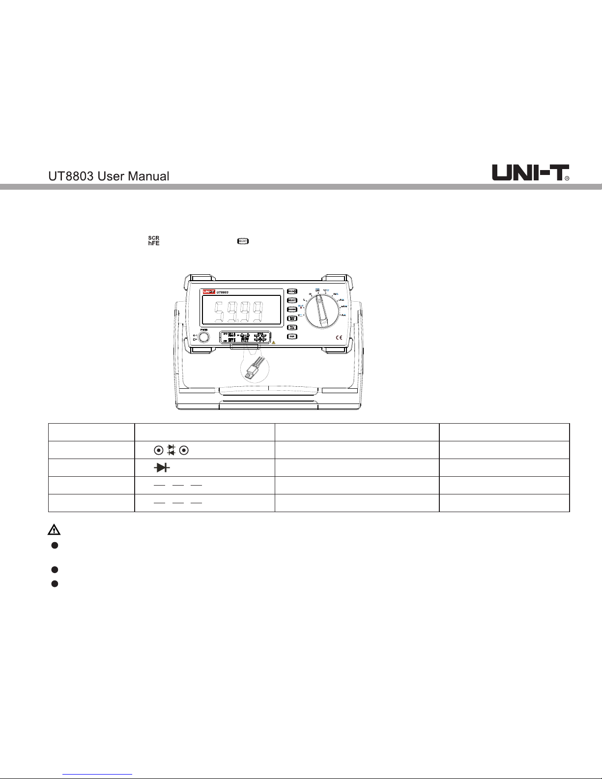
8.Audion measurement
a) Insert UT-S03A (multi-function socket) to the corresponding socket.
b) Switch the dial to position, press to switch to audion measurement.
c) Insert the audion to UT-S03A. Pins of audion should correspond with jacks of UT-S03A.
B(basic), E(emission), C(collector)
d) Reading is displayed.
Note:
Do not input voltage over 30V (sine wave RMS), (peak value 42V) or DC 60V.
For accuracy, insert the audion correctly to the multi-function socket. Pay attention to the polarity.
DIGITAL MULTIMETER
True RMS
6000 Counts
CAT II 600V
Page 18
17
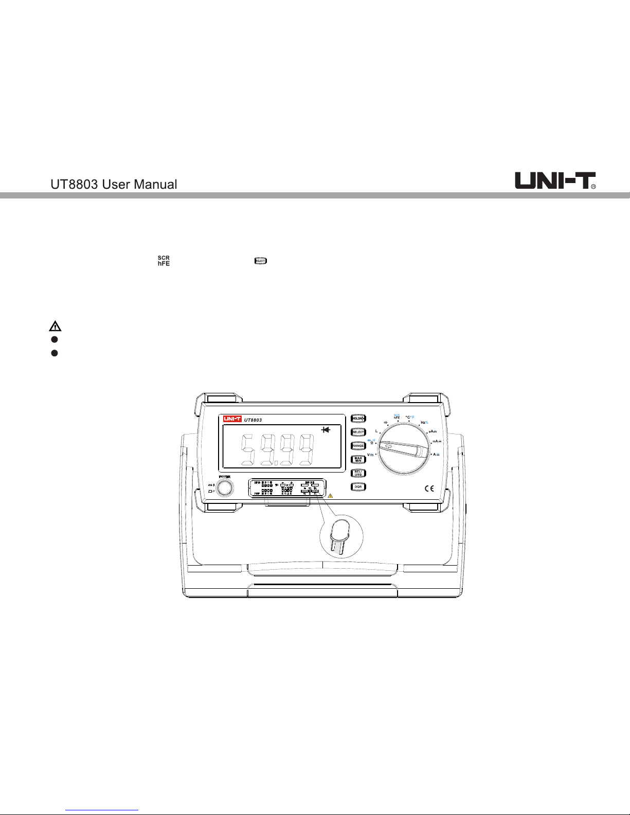
9.Thyristor measurement
a) Insert UT-S03A (multi-function socket) to the instrument.
b) Switch the dial to position, press to switch to thyristor measurement.
c) Insert SCR correctly to UT-S03A: G(gate), A(anode), K(cathode)
d) Display as following:
DIGITAL MULTIMETERDIGITAL MULTIMETER
True RMSTrue RMS
6000 Counts 6000 Counts
CAT II 600V
CAT II 600V
Note:
Before measurement, please switch off all power supply and fully discharge all capacitors.
Pay particular attention to capacitors with high voltage.
Do not input voltage over 30V (sine wave RMS), (peak value 42V) or DC 60V.
Disconnect test leads with the circuit after measurement.
LCD display
0.1V~2V
0.1V~2V
ERR
OL
Status
Normal
Normal
Bad contact
Not connected/bad contact
SCR polarity
Two-way
One-way
Unknown
Unknown
SCR polarity symbol
Page 19
18
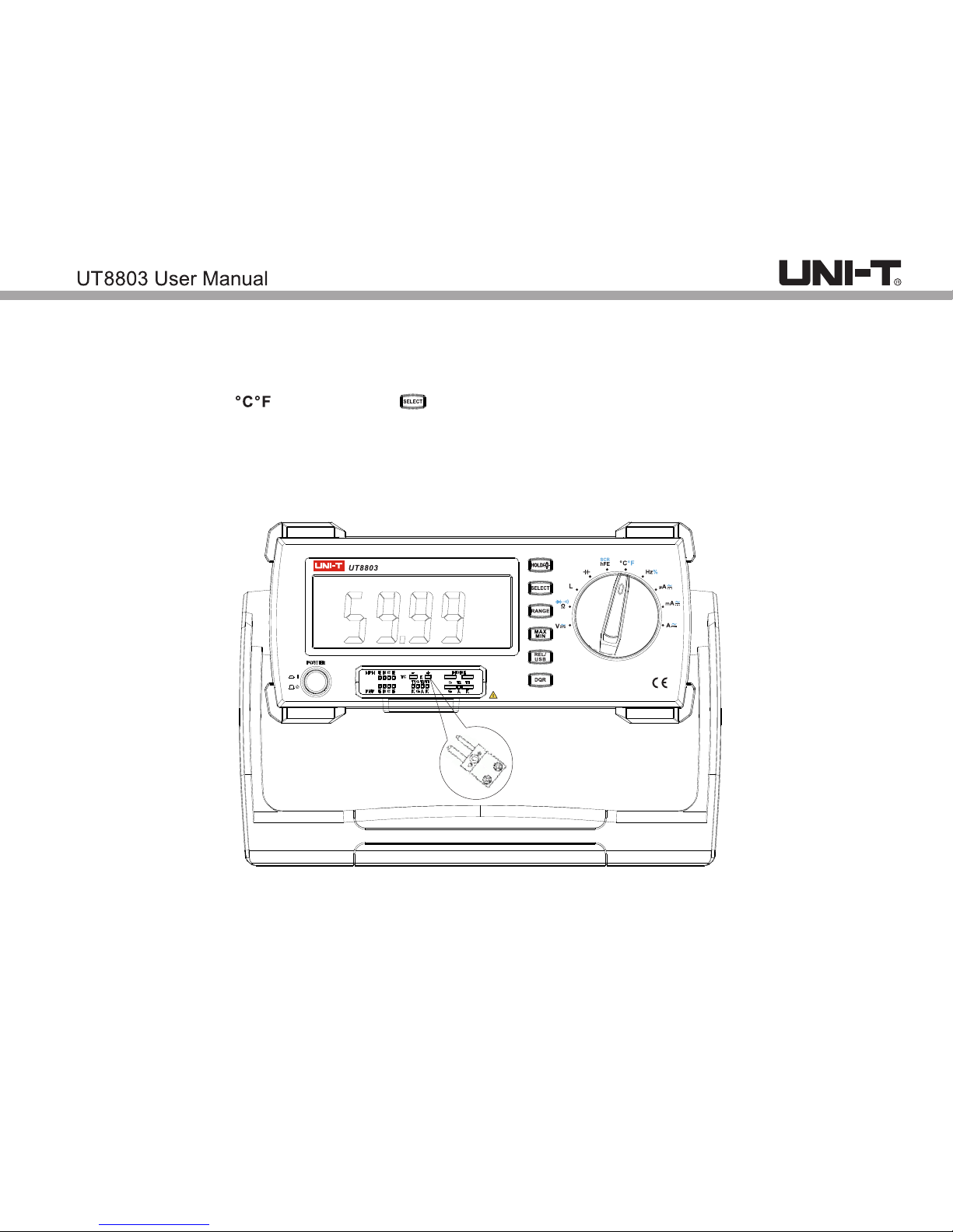
10.Temperature measurement
a) Insert UT-S03A(multi-function socket) to the instrument.
b) Switch the dial to position, press button to switch temperature unit. OL appears if no
thermocouple connected.
c) Insert the thermocouple to UT-S03A, pay attention to the polarity. (reverse polarity results in negative
reading.)
DIGITAL MULTIMETER
True RMS
6000 Counts
CAT II 600V
Page 20
19
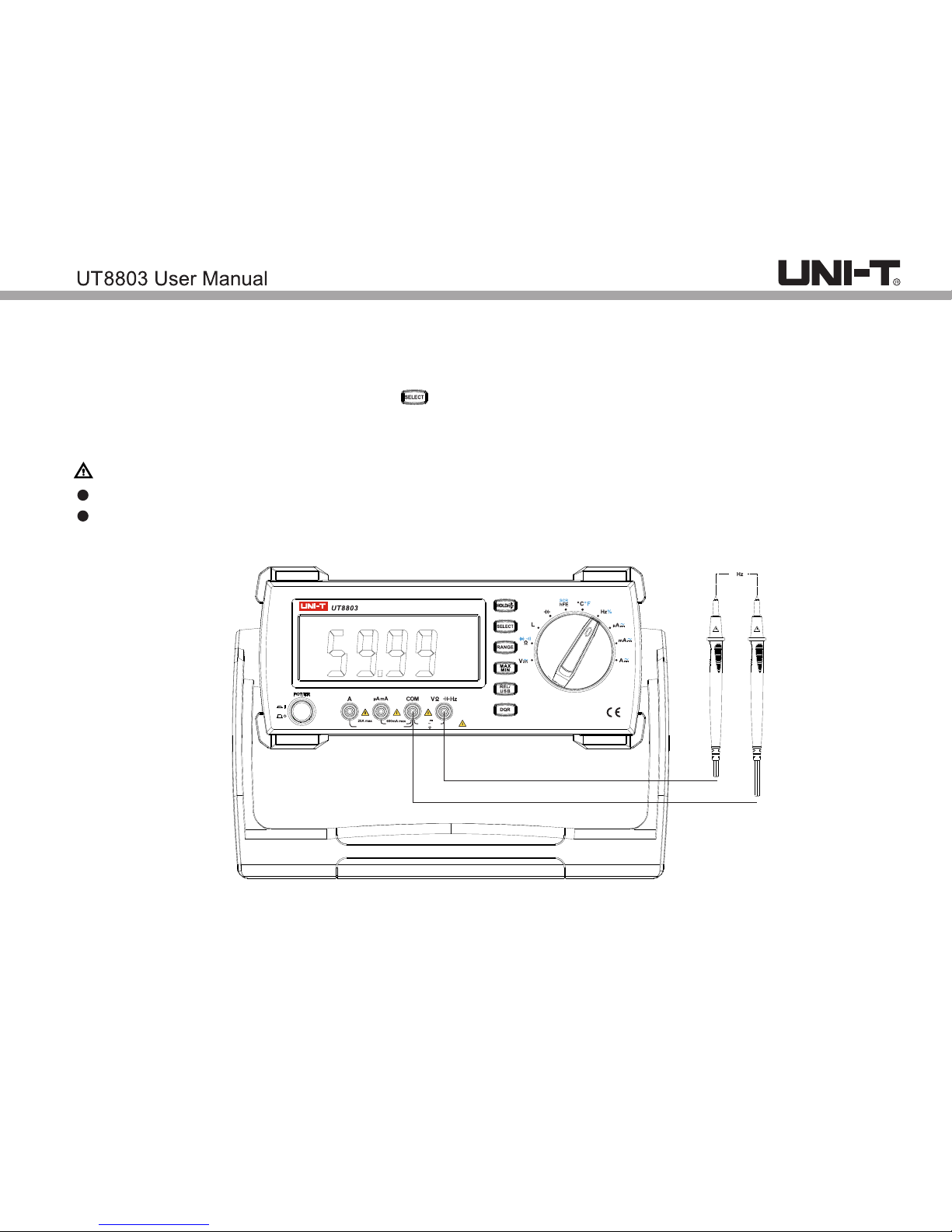
11.Frequency measurement.
a) Insert red test lead to Hz% jack, black to COM jack.
b) Switch the dial to Hz% position, press to frequency measurement.
c) Connect the test leads with frequency source in parallel.
d) Reading is displayed.
Note:
Do not input over 30V AC or it will pose shock hazard.
Disconnect test leads with the circuit after measurement.
黑
红
L
DIGITAL MULTIMETER
True RMS
6000 Counts
FUSED
CAT II 600V
FUSED
MAX 30 sec EACH 15min
1000V
750V
max
Page 21
黑
黑 黑
红
红 红
L
L L
DIGITAL MULTIMETER
DIGITAL MULTIMETER DIGITAL MULTIMETER
True RMS
True RMS True RMS
6000 Counts
6000 Counts 6000 Counts
FUSED
CAT II 600V
FUSED
MAX 30 sec EACH 15min
1000V
750V
max
FUSED
CAT II 600V
FUSED
MAX 30 sec EACH 15min
1000V
750V
max
FUSED
CAT II 600V
FUSED
MAX 30 sec EACH 15min
1000V
750V
max
20
12.Duty ratio measurement
a) Insert red test lead to Hz% jack, black to COM jack.
b) Switch the dial to Hz% position, press to enter duty ratio measurement.
c) Connect the test leads with signal source in parallel.
d) Reading is displayed.
Note:
Do not input over 36V AC or it will pose shock hazard.
Disconnect test leads with the circuit after measurement.
Duty ratio measurement function of UT8803 is only for reference.
13.Current measurement
a) Insert red test lead to μA mA or A jack, black to COM jack.
b) Switch the dial to position, press to enter AC/DC measurement.
c) Connect the test leads with signal source in series.
d) Reading is displayed. When measuring AC current, reading is sine wave RMS.
Note:
Before measurement, switch off the power supply of the circuit to be measured, fully discharge all high
voltage capacitors.
If the current is unknown, select the maximum range and reduce it accordingly.
Do not connect the test leads with circuit in parallel.
Disconnect test leads with the circuit after measurement.
When measuring current>20A, measurement time should be less than 30s with over 15 mins interval
or it may pose shock hazard or injury to human.
Page 22

21
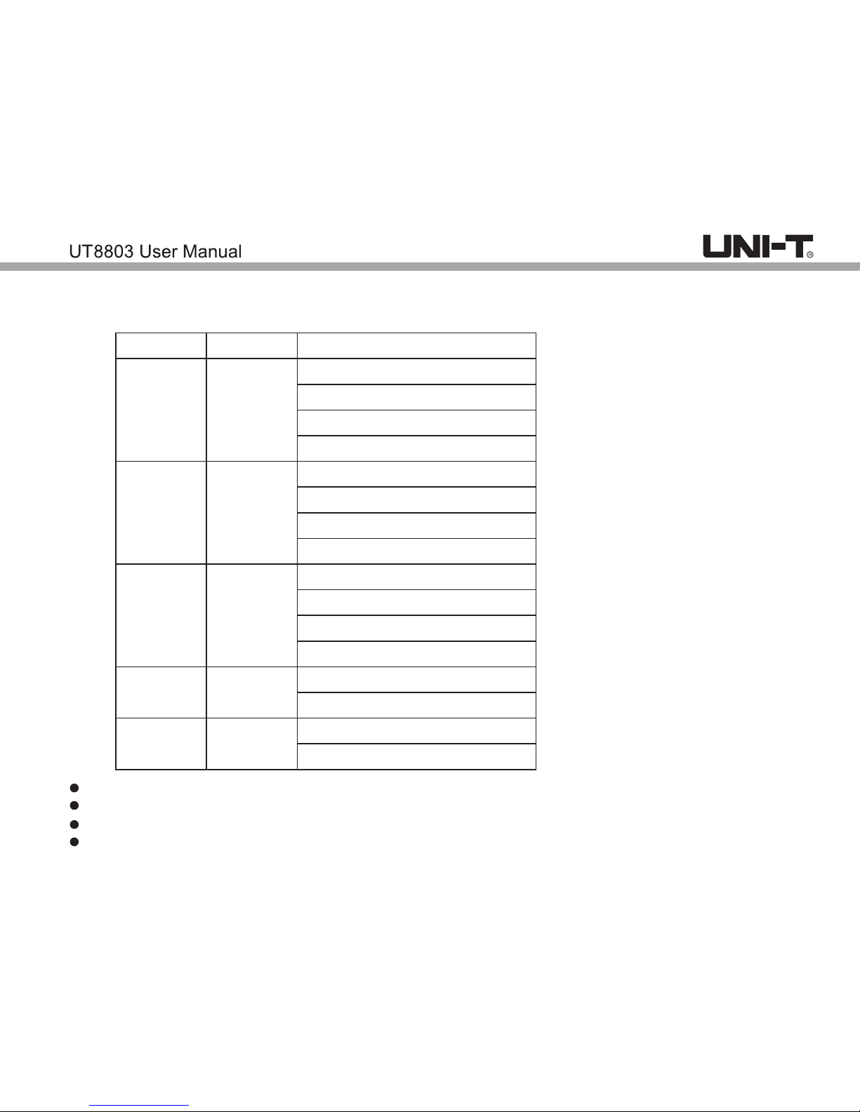
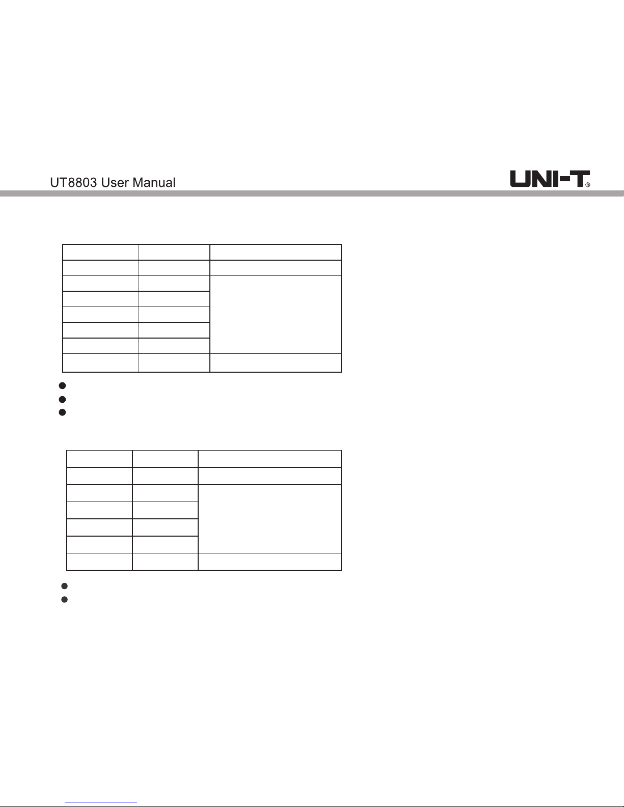
IX. Technical specifications
Accuracy: ± (% of reading + least significant digit), 1 year warranty
Ambient temperature: 18˚C~28˚C
Ambient humidity: ≤75% RH
1.DC voltage
6000mV
6V
60V
600V
1000V
0.1mV
1mV
10mV
100mV
1V
±(0.5%+2)
±(0.3%+2)
±(0.5%+3)
Range
Resolution
Accuracy
Input impedance: 10MΩ; Maximum voltage:1000V
Page 23
22
40Hz-1kHz:±(0.6%+5)
≥1kHz-10kHz:±(1.2%+5)
≥20kHz-100kHz:±(4%+5)
≥10kHz-20kHz:±(3%+5)
40Hz-1kHz:±(0.6%+5)
≥1-10kHz: ±(1.2%+5)
≥10-20kHz: ±(3%+5)
≥20-100kHz: ±(4%+5)
40Hz-1kHz: ±(0.6%+5)
≥1-10kHz: ±(1.5%+5)
≥10-20kHz: ±(3%+5)
≥20-100kHz: ±(8%+5)
40 Hz-1kHz: ±(0.6%+5)
≥1-10kHz: ±(3.5%+5)
40Hz-1kHz: ±(1.2%+5)
≥1-3kHz: ±(3%+5)
0.1mV
1mV
10mV
100mV
1V
600mV
6V
60V
600V
750V
Input impedance: 10MΩ; Maximum voltage:750Vrms.
Frequency response: 40Hz~100kHz.
Display: Sine wave true RMS (average response)
In open status, there is residual reading which do not affect accuracy.
Range
Resolution
Accuracy
2.AC voltage
Page 24
23
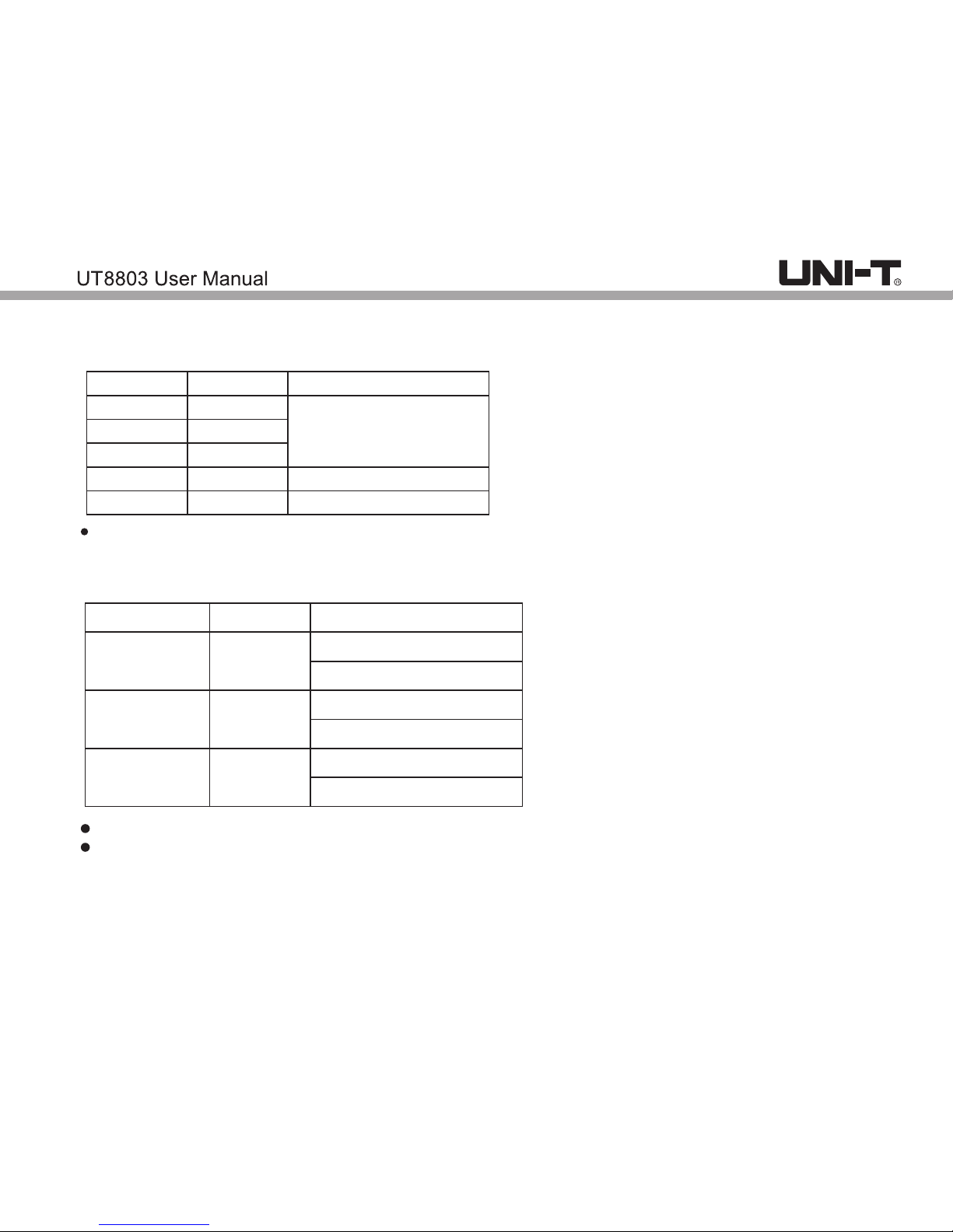
3.DC current
600μA
6mA
60mA
600mA
20A
0.1μA
1μA
10μA
100μA
10mA
±(0.8%+3)
±(1.5%+3)
±(2%+5)
40Hz-10kHz ±(1%+5)
>10-15kHz:±(2%+5)
40Hz-5kHz:±(1%+5)
>5kHz-15kHz:±(3%+5)
40Hz-1kHz:±(2.0%+6)
>1 -15kHz;±(3.0%+6)k
0.1-10μA
100μA
10mA
600 A-6mAμ
60mA-600mA
20A
Range
Resolution
Accuracy
If current ≥10A, measure time should be less than 30s with 15mins interval. In open status, allowable
error: ≤5 residual digits.
4.AC current
Range
Resolution
Accuracy
Frequency response: 40Hz~15kHz.
If current ≥10A, measure time should be less than 30s with 15mins interval. In open status, allowable
error: ≤5 residual digits.
Page 25
24
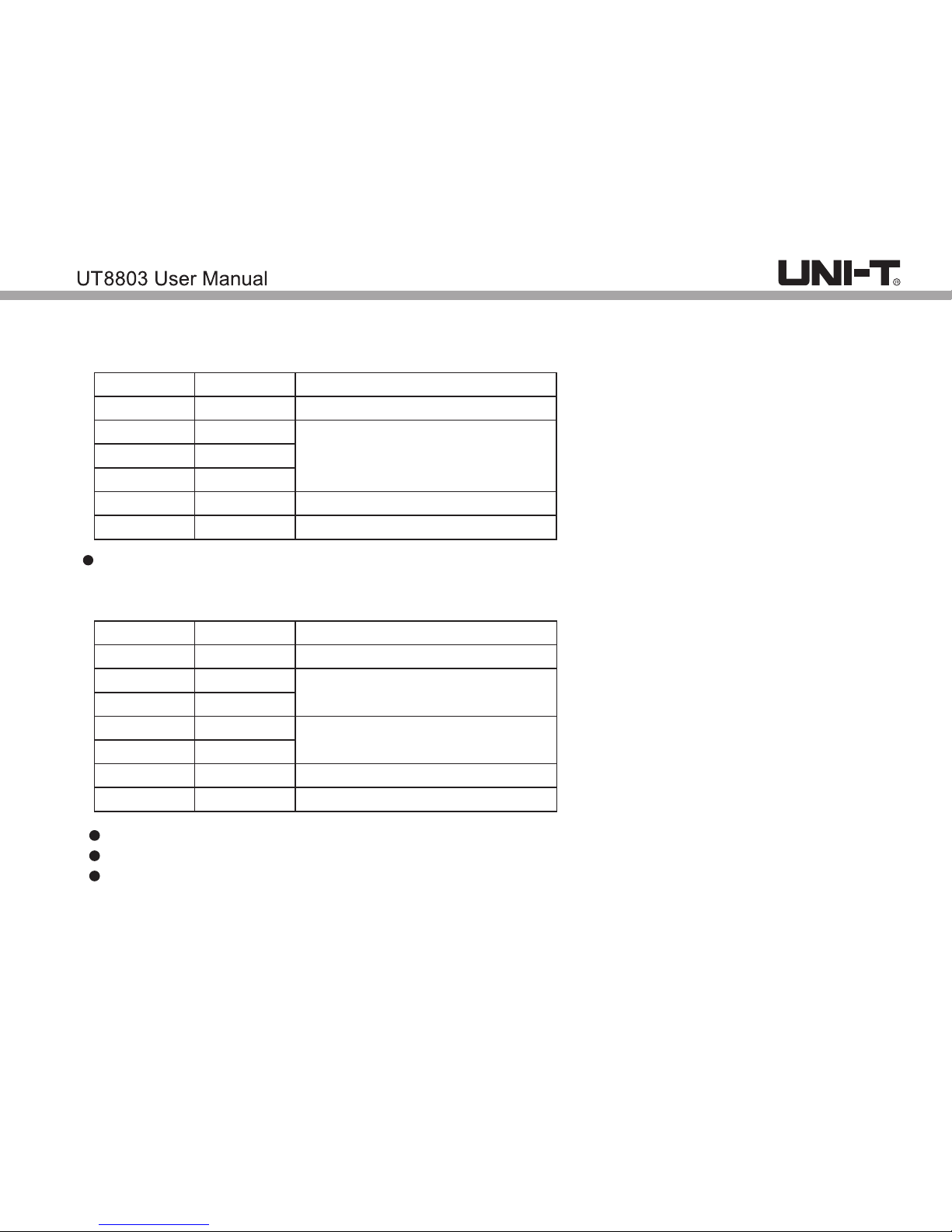
5. Resistance
600Ω
6kΩ
60kΩ
600kΩ
6MΩ
60MΩ
0.1Ω
1Ω
10Ω
100Ω
1 Ωk
10kΩ
±(1%+5)
±(0.8%+5)
±(2%+5)
±(5%+5)
Range
Resolution
Accuracy
Open circuit voltage: -1.2V
6.Capacitance
Minimum measure range: >8PF;
If capacitance >6.6mF, OL symbol appears
Input impedance: 4kΩ
6nF
60nF
600nF
6µF
60 Fµ
600 Fµ
6mF
1PF
10PF
100pF
1nF
1nF
10nF
100 Fµ
±(2.5%+5)
±(1.5%+5)
±(3%+10 )
±(5%+5 )
±(10%+8 )
Range
Resolution
Accuracy
Page 26
25
7.Inductance
600µH
6mH
60mH
600mH
6H
60H
100H
0.1µH
1 Hµ
10 Hµ
100 Hµ
1mH
10mH
100mH
±(2.5%+5)
±(2%+5 )
60Ω
600Ω
6kΩ
60kΩ
600 Ωk
6MΩ
0.01Ω
0.1Ω
1Ω
10Ω
100Ω
1kΩ
±(2%+10)
±(1%+5)
±(5%+5)
Range
Resolution
Accuracy
Measure voltage: 0.6V RMS
Minimum measure range: >16μH
Input impedance: 4KΩ
8.Equivalent resistance (ACR) Ω
Range
Resolution
Accuracy
Minimum measure range: >0.1Ω
Input impedance: 4KΩ
Only for reference
Page 27
26
600Hz
6kHz
60kHz
600kHz
6MHz
20MHz
5%~95%
0.1Hz
1Hz
10Hz
100Hz
1kHz
10kHz
0.10%
±(0.1%+10)
SCR
hFE
10mV
10mV
1β
0.5~0.8V
0.1~2V
Sensitivity: frequency<600KHz, amplitude>1.5Vrms or frequency>600kHz, amplitude>2.5Vrms,
minimum input>5Hz.
Duty ratio measurement only applicable for square wave ≤10kHz.
2Vpp≤input amplitude≤30Vpp
Frequency≤1kHz, Duty: 5.0%~95.0%
Frequency>1kHz, Duty: 30.0%~70.0%
Only for reference
Range
Resolution
Accuracy
9.Frequency/ duty ratio
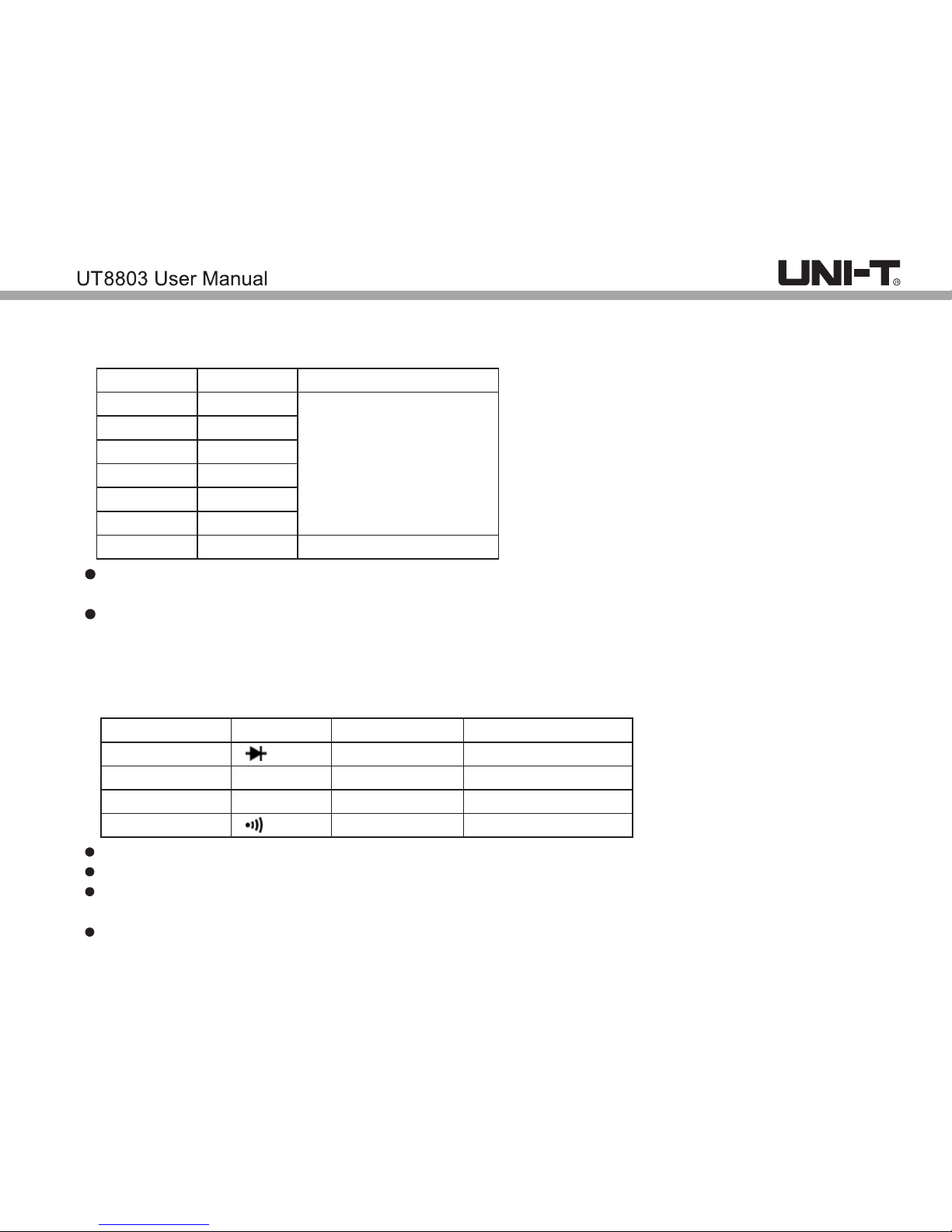
10.Diode/audion/thyristor/continuity
Function
Diode
SCR test
Audion hFE
Continuity
Position Resolution
Accuracy
No specified
No specified
About 0.1Ω
When measuring hFE, Ib0: about 10μA; Vce: about 2.8V
When measuring diode, Silicon PN junction onset voltage drop: 0.5~0.8V, open status voltage: 8V
When measuring continuity, in good conducted circuit, resistance <10Ω, buzzer goes off;
in open circuit, resistance>30Ω, buzzer does not go off.
When measuring SCR, onset voltage drop: 0.1~2V; open circuit voltage: about 9V.
Page 28

27
-40 -0℃ ℃
>0 -400℃ ℃
>400 -1000℃ ℃
-40 -32℉℉
>32 -752 ℉ ℉
>752 -1832℉ ℉
±2%+5℃
±1%+5℃
±2%+3℃
±2%+9℉
±1%+9℉
±2%+6℉
1℃
1℉
Display
0.1V~2V
0.1V~2V
ERR
OL
Status
Normal
Normal
SCR bad contact
SCR not connected or bad contact
SCR polarity
Two-way
One-way
Unknown
Unknown
SCR polarity indicator
11.Temperature
Range
Resolution
Accuracy
K-type thermocouple applicable
Page 29
28
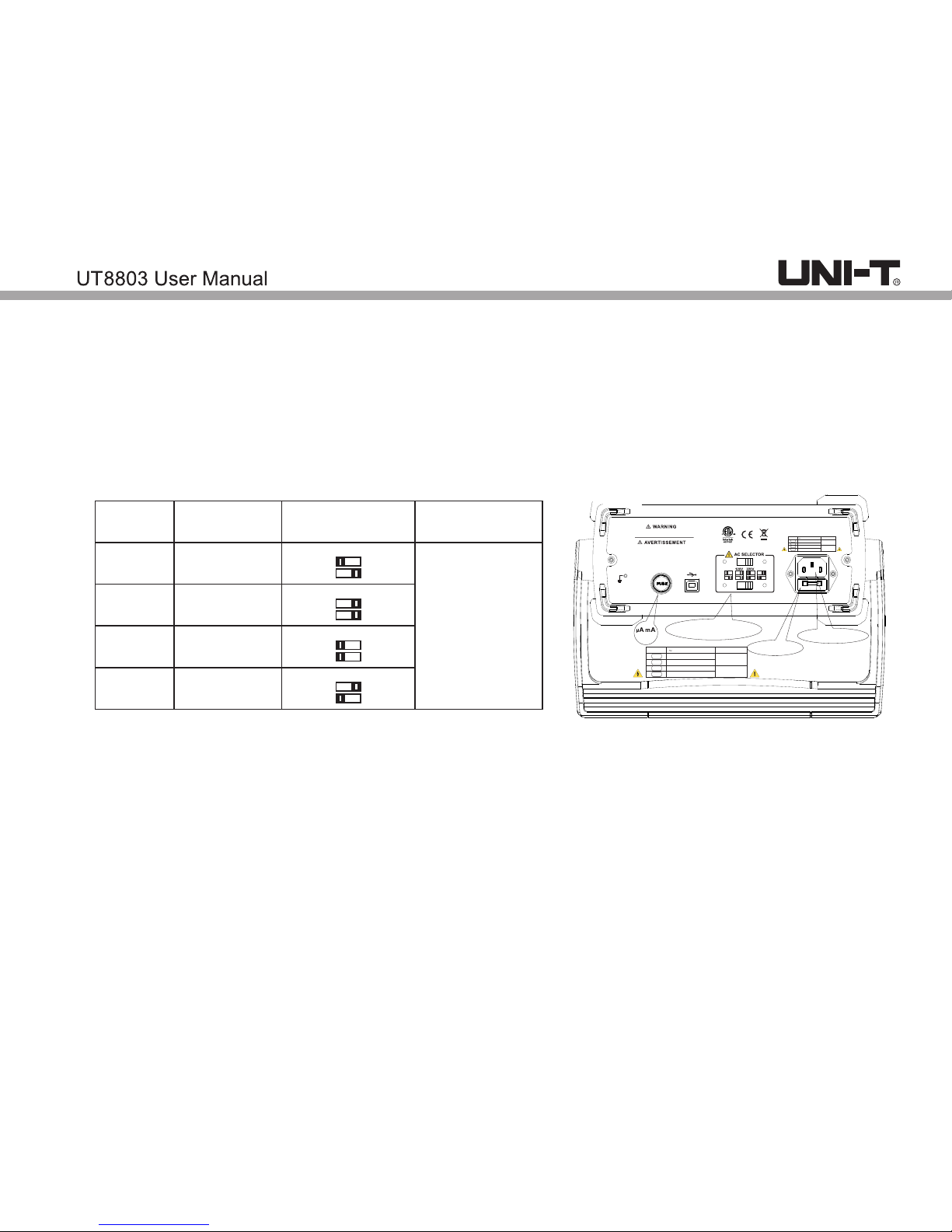
X.Power supply and fuse replacement
1.Power supply setting
2.Fuse replacement
F2 F600mA 1000V
100V
240V
FUSE
AC power FUSE
AC power input socket
Power supply voltage setting
TO AVOID ELECTRIC SHOCK, REMOVE THE TEST
LEADS AND TURN OFF THE POWER INPUT BEFORE
OPENING THE CASE AND REPLACING THE FUSE.
POUR ÉVITER UN CHOC ÉLECTRIQUE, RETIREZ
LES CORDONS DE MESURE ET ÉTEIGNEZ
L'ALIMENTATION AVANT D'OUVRIR LA CASE
ET DE REMPLACER LE FUSIBLE.
SELECTOR LINE(45-440Hz,28VA Max) FUSE
100V
120V
AC 100V
AC 120/127V
220V
240V
AC 220/230V
AC 240V
AC 250V T250mA
AC 250V T125mA
SELECTOR LINE(45-440Hz,28VA Max) FUSE
100V
120V
AC 100V
AC 120/127V
220V
240V
AC 220/230V
AC 240V
AC 250V T250mA
AC 250V T125mA
1) Turn the red switch to the corresponding position
2) Setting steps:
a. Unplug the power cord
b. Turn the red switch to corresponding position
c. Selectable positions are shown below
1) Unplug the test leads from the instrument.
2) Turn off the power supply for the instrument
3) Open the fuse housing with a screwdriver.
4) Replaced the fuse with new one.
100V
120V
220V
240V
100V
120V/127V
220V/230V
240V
Position
Voltage
Demonstration
Description
Input
corresponding
voltage
1
2
3
4
Page 30

29
 Loading...