

UNI-T UT81B, UT81A Operating Manual

Model UT81B
OPERATING MANUAL

Chapter Title Page
6
6
7
8
8
10
11
11
12
13
15
15
15
17
19
19
20
20
22
27
29
31
33
Model UT81B: OPERATING MANUAL
1
Table of Contents
1 Before You Start
Overview
Unpacking Inspection
Safety Information
Rules For Safe Operation
International Electrical Symbols
2 Using The Testing Tool
Reading the screen
The Meter Structure
Functional Buttons
3 Making Measurements
A. Scope Mode
i. Setting up the Sleep Mode, Contrast, Beep
ii. ACV, DCV, Hz, ACV and DCA Range
iii. Trigger function
iv. Waveform data save and recall
B. Digital Multimeter Mode
i. Measuring Voltages
ii. Measuring Currents
iii. Measuring Resistance
iv. Testing Diodes
v. Testing for Continuity
vi. Measuring Frequency / Duty Cycle

2
Model UT81B: OPERATING MANUAL
35
37
38
38
39
40
41
41
42
43
43
44
44
45
45
46
46
47
48
49
49
50
Chapter Title Page
Table of Contents
A.
B.
C.
D.
E.
F.
G.
DC Voltage
AC Voltage
DC Current
AC Current
Resistance
Diode Test
Continuity Test
vii. Measuring Capacitance
4 Using Software
5 Maintenance The Test Tool
A. General Service
B. Replacing the Fuses
C. Replacing the Battery
6 Specifications
Safety and Compliances
Physical Specifications
General Specifications (Digital Multimeter)
General Specifications (Scope)
Feature Summary
Basic Specifications (Digital Multimeter)
Basic Specifications (Scope)
Detailed Accuracy Specifications

3
Model UT81B: OPERATING MANUAL
50
51
Chapter Title Page
Table of Contents
H. Frequency and Duty Cycle %
I. Capacitance

4
Model UT81B: OPERATING MANUAL
7
10
11
13
Table Title Page
List of Tables
1-1 Unpacking Inspection
1-2 International Electrical Symbols
2-1 Reading the Screen
2-2 Functional Buttons

5
Model UT81B: OPERATING MANUAL
12
13
17
21
23
24
25
27
29
31
33
35
39
40
Figure Title Page
List of Tables
2-1 Meter Structure
2-2 Functional Buttons
3-1 Waveform Display
3-2 Voltages Measurement
3-3 µA Range Measurement
3-4 mA Range Measurement
3-5 10A Range Measurement
3-6 Resistance Measurement
3-7 Diode Test
3-8 Continuity Test
3-9 Frequency / Duty Cycle Measurement
3-10 Capacitance Measurement
5-1 Fuse Replacement
5-2 Battery Replacement

6
Model UT81B: OPERATING MANUAL
Overview
This Operating Manual covers information on safety
and cautions. Please read the relevant information
carefully and observe all the Warnings and Notes
strictly.
Warning
To avoid electric shock or personal injury, read the
“Safety Information” and “Rules for Safe Operation”
carefully before using the Meter.
Scope Digital Multimeter UT81B (hereafter referred to
as “the Meter”) is a 3999 counts and 3 3/4 digits adopting
digital control techique with both waveform and
multimeter all in one.
Scope mode is a complete intelligent measurement
system including signal input, sampling, data process,
auto search and waveform save and recall. It has
Chapter 1
Before You Start
bandwidth 8MHz, real-time sample rate 40MS/s with
peak rate sampling process can catch up pulse industrial
signal. It can measure AC/DC engine, transducer,
circuit, control, UPS and industrial equipments. It is an
ideal tools in professional repairing industries.
Digital Multimeter mode can measure AC voltage and
current, DC voltage and current, Resistance,
Capacitance, Frequency, Duty Cycle, Diodes and
Continuity.

7
Item Description Qty
Model UT81B: OPERATING MANUAL
Unpacking Inspection
Open the package case and take out the Meter. Check the items shown on Table 1-1 carefully to see any missing
or damaged part:
In the event you find any missing or damage, please contact your dealer immediately.
1
2
3
4
5
6
7
8
9
English Operating Manual
USB interface cable
CD-ROM (Installation Guide & Computer Interface Software)
Test Lead
Alligator Clip
Power Adaptor
1.5V Batteries (R6)
Scope Probe (available at extra cost)
BNC probe (available at extra cost)
1 piece
1 piece
1 piece
1 pair
1 piece
1 piece
4 pieces
1 piece
1 piece
Table 1-1. Unpacking Inspection

8
Model UT81B: OPERATING MANUAL
Safety Information
This Meter complies with the standards IEC61010 safety
measurement requirement: in pollution degree 2,
overvoltage category (CAT. II 1000V, CAT.III 600V) and
double insulation.
CAT.II: Local level, appliance, PORTABLE EQUIPMENT
etc., with smaller transient overvoltages than CAT. III
CAT. III: Distribution level, fixed installation, with smaller
transient overvoltage than CAT. IV
Use the Meter only as specified in this operating manual,
otherwise the protection provided by the Meter may be
impaired.
In this manual, a Warning identifies conditions and
actions that may pose hazards to the user, or may
damage the Meter or the equipment under test.
A Note identifies the information that user should pay
attention to.
Warning
l
l
l
International electrical symbols used on the Meter and
in this Operating Manual are explained on page 10.
Rules For Safe Operation
To avoid possible electric shock or personal injury,
and to avoid possible damage to the Meter or to the
equipment under test, adhere to the following rules:
Before using the Meter inspect the case. Do not
use the Meter if it is damaged or the case (or
part of the case) is removed. Look for cracks
or missing plastic. Pay attention to the insulation
around the connectors.
Inspect the test leads for damaged insulation or
exposed metal. Check the test leads for
continuity. Replace damaged test leads with
identical model number or electrical
specifications before using the Meter.
Do not apply more than the 1000V rms between
any terminal and grounding to avoid electric

9
Model UT81B: OPERATING MANUAL
shock or damages to the Meter.
The rotary switch should be placed in the right
position and no any changeover of range shall
be made during measurement is conducted to
prevent damage of the Meter.
When the Meter working at an effective voltage
over 60V in DC or 42V rms in AC, special care
should be taken for there is danger of electric
shock.
Use the proper terminals, function, and range
for your measurements.
Do not use or store the Meter in an environment
of high temperature, humidity, explosive,
inflammable and strong magnetic field. The
performance of the Meter may deteriorate after
dampened.
When using the test leads, keep your fingers
behind the finger guards.
Disconnect circuit power and discharge all highvoltage capacitors before testing resistance,
continuity, diodes.
Before measuring current, check the Meter’s
fuses and turn off power to the circuit before
l
l
l
l
l
l
l
connecting the Meter to the circuit.
Replace the battery as soon as the battery
indicator
appears. With a low battery, the
Meter might produce false readings that can lead
to electric shock and personal injury.
When servicing the Meter, use only the same
model number or identical electrical
specifications replacement parts.
The internal circuit of the Meter shall not be
altered at will to avoid damage of the Meter and
any accident.
Soft cloth and mild detergent should be used to
clean the surface of the Meter when servicing.
No abrasive and solvent should be used to
prevent the surface of the Meter from corrosion,
damage and accident.
The Meter is suitable for indoor use.
Turn the Meter off when it is not in us e and take
out the battery when not using for a long time.
Constantly check the battery as it may leak when
it has been using for some time, replace the
battery as soon as leaking appears. A leaking
battery will damage the Meter.
l
l
l
l
l
l
l

10
Model UT81B: OPERATING MANUAL
International Electrical Symbols
AC or DC
DC Measurement
AC Measurement
Continuity Test
Diode
Grounding
Double Insulated
Warning. Refer to the Operating Manual
Deficiency of Built-In Battery
Conforms to Standards of European Union
Symbols used on the Meter and in this manual are
explained in Table1-2.
Table 1-2. International Electrical Symbols

11
Model UT81B: OPERATING MANUAL
Chapter 2
Using the T esting Tool
Reading the Screen
Description
The degree of contrast
Sleep mode time
Display backlight
Beeper on and off
Confirm
Increase
Decrease
Waveform moves up
Waveform moves down
Increase a range
The screen displays the menu that provides the following
choices available:
Table 2-1. Reading the Screen
Description
Decrease a range
Increase a time base
Decrease a time base
Waveform moves right
Waveform moves left
Trigger moves up
Trigger moves down
Trigger slope adjustment
Auto trigger mode
Normal trigger mode
Single trigger mode
Display
Contrast
Auto Off
BK Light
BEEP
ENTER
MOVE
MOVE
RANG
Display
RANG
BASE
BASE
BASE >
BASE <
TRIG
TRIG
SLOP
AUTO
NORM
SHOT
Table 2-1. Reading the Screen

12
Model UT81B: OPERATING MANUAL
Figure 2-1. Meter Structure
The Meter Structure
The Figure 2-1 shows the Meter structure.
1. USB Terminals
2. LCD Display
3. Functional Buttons
4. Rotary Switch
5. Power adaptor Input Terminals
6. 10A Input Terminal
7. mAµA Input Terminals
8. COM Input Terminal
9. Other Input Terminals
13
Model UT81B: OPERATING MANUAL
Figure 2-2. Functional Buttons
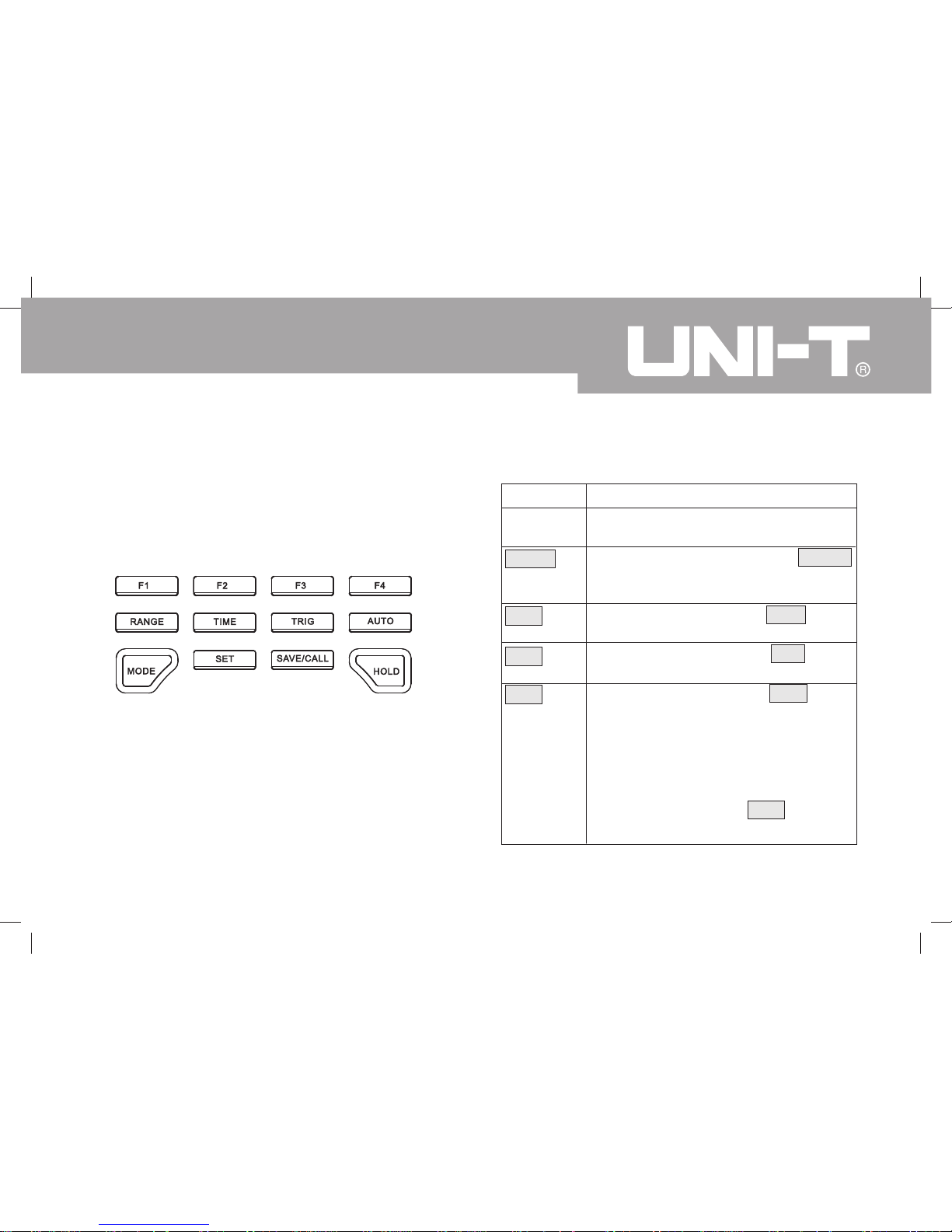
Table 2-2. Functional Buttons
Description
Software functional buttons, details
please refer to the below.
Under scope mode, Press Range
button to switch between DC and AC
measurement
Under scope mode, press Time button
to set the X-axis of time base.
Under scope mode, press Trig button
to change the trigger mode.
In multimeter mode: Press Auto button
to enter autoranging mode when
measuring resistance, voltage and
current. This button is invalid when
measuring capacitance, diode, continuity
buzzer and capacitance.
In scope mode: Press Auto button to
set the amplitude and time base to auto.
Buttons
F1, F2,
F3 and F4
Range
Time
Trig
Auto
Functional Buttons
The buttons activate features that augment the function
selected with the rotary switch. The buttons are shown
in Table 2-2.

14
Model UT81B: OPERATING MANUAL
Table 2-2. Functional Buttons
Buttons
Mode
Set
Save/Call
Hold
Description
To switch between waveform display
(scope mode) and digital reading
(multimeter mode). This button is only
valid when under voltage, frequency,
currents mode.
Press Set button to set the auto power
off, backlight, contrast and beep
Under scope mode, press Save/Cal to
store and recall data.
Press Hold button to enter or exit hold
mode.
15
Model UT81B: OPERATING MANUAL
Chapter 3
Making Measurement
Introduction
Chapter 3 explains how to make measurements.
You could turn the Meter off by turning to OFF position
or set up the sleep mode from 1-30 minutes. Please
must ensure the Meter is not under sleep mode if you
turn the Meter on but without display.
To avoid false readings, which could lead to possible
electric shock or personal injury, replace the battery as
soon as the battery indicator “
” appears.
A. Scope Mode
l The LCD top right part display: RUN, HLD, REV
l The LCD top right corner has battery icon to indicate
when the battery is lower than 5V.
l Under scope mode, both reading and waveform
will be displayed.
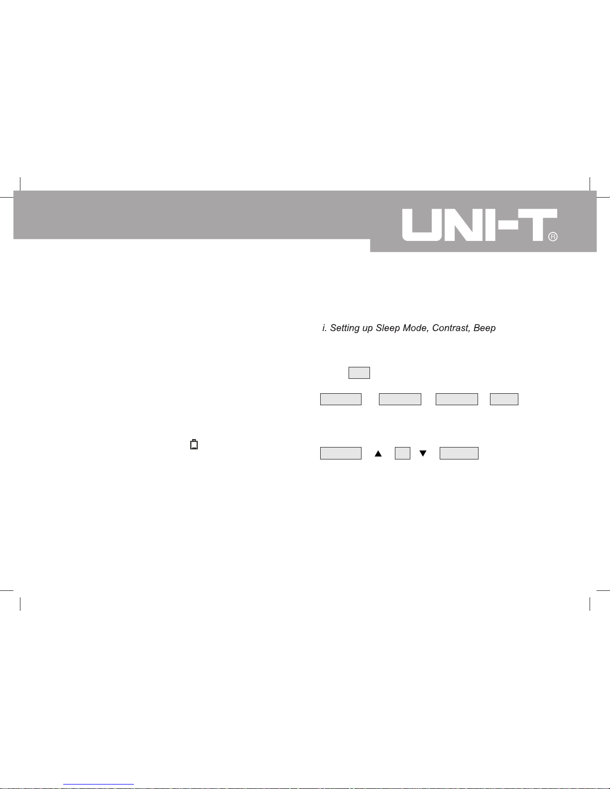
Based on the working environment to set up sleep
mode, contrast, beep
Press Set button to set the auto power off, display
backlight, contrast and beep
Auto off Bk Light Contrast Beep
F1 F2 F3 F4
F1: Set auto power off time
Auto off 15 ENTER
F1 F2 F3 F4
The time level is from OFF, 1 to 30 minutes. Press F4
to confirm, save and return. Press functional button to
exit and the setting remains unchanged.

16
Model UT81B: OPERATING MANUAL
F2: Set the Display Backlight
BK Light 15 ENTER
F1 F2 F3 F4
The brightness level from 0 to 31. Press F4 to
confirm, save and return. Press functional buttons
to exit, the setting is kept, but will not save. The
setting will be lost after power off.
F3: Set the LCD contrast
Contrast 15 ENTER
F1 F2 F3 F4
The contrast level from 0 to 31. Press F4 to confirm,
save and return. Press functional buttons to exit,
the setting is kept, but will not save. The setting will
be lost after power off.
F4: Set the beeps features, it can only be used under
resistance, diode and continuity measurement.
Beep ON OFF ENTER
F1 F2 F3 F4
F2 : to turn the beep on
F3 : to turn the beep off
F4 : to confirm , save and return
Press functional buttons to exit, the setting is kept, but
will not save. The setting will be lost after power off.
 Loading...